Abstract
Rotor mass imbalance is the main cause of vibration overload of high-end turbine units, which can easily induce a variety of failures such as shaft tile and seal wear, and blade breakage. The online automatic balancing system can solve the problem of imbalance of rotor mass during the operation of the equipment, and at the same time can ensure the long-term stable operation of the equipment. Therefore, a new pneumatic–liquid on-line automatic balance (PLOABS) system is proposed for high-end turbine units, which has the advantages of simple structure, no moving parts in the rotating element, closed action environment, reversible balancing process and can maintain the original state when restarted. Using ANSYS software, the gas driving force and the internal gas–liquid rotating flow field of the actuator are simulated and analyzed, and the actuator structure has been further optimized. At the same time, a set of the PLOABS system is built to conduct automatic balancing experiments. The results showed that the rotor amplitude was reduced from 18.3 to 10.6 μm, which verified the feasibility and effectiveness of the PLOABS technology and laid the foundation for the subsequent engineering application of the PLOABS technology.
1. Introduction
Large rotating equipment such as turbogenerators, large wind turbines and centrifugal compressors are usually the key equipment of national pillar industries such as chemical industry, electric power and aerospace [1,2]. However, the rotor quality imbalance caused by production manufacturing, assembly process, uneven distribution of materials and uneven wear during operation, under the condition of high-speed rotation, will cause severe vibration due to uneven mass imbalance of the rotor during operation and affect the smooth and efficient operation of the equipment [3,4]. At present, field dynamic balancing is used as the main dynamic balance method in large rotating equipment. Domestic and foreign scholars keep reducing the number of times they balance and making the balancing process more accurate and the balancing scheme better, based on influence coefficient method [5,6], modal shape analysis balance method [7,8], balance method without trial weight [9], balancing method based on holospectrum [10] and other field dynamic balancing methods that are constantly being optimized. However, the traditional field dynamic balancing in order to achieve a higher balance accuracy usually needs to start and stop many times and apply test weight and test the vibration response of the machine tool. Each field dynamic balancing process takes a long time, and has high requirements for operators, so the improvement of production efficiency and the reduction of processing cost are restricted by the disadvantage of passive balance [11,12].
During the operation of the equipment, the problem of rotor mass unbalance vibration can be solved by the on-line automatic balancing system, and the long-term stable operation of the equipment can be guaranteed by it [13,14,15]. The on-line automatic balancing system is composed of three parts: sensor, controller and balance actuator. When the sensor detects the unbalanced vibration signal, the controller issues control instructions after calculation, and the balance actuator responds after receiving the control instructions, and finally the unbalanced vibration is suppressed [16]. Mature online automatic balancing products are mainly divided into electromagnetic, motor and liquid, and have been applied to high-speed rotating motors, aircraft propellers, spindle, grinding wheel for high-end machine tools and other fields [17,18,19]. For large rotating equipment, the rotor diameter is larger and the working environment is more complex, so the existing automatic balancing system cannot adapt to it. Therefore, it will bring great economic and social benefits to design an automatic balance system that can apply an automatic balancing system to large rotating equipment [20].
Compared with electromagnetic and motor automatic balancing actuators, liquid automatic balancing actuators have the advantages of simple structure and large balance capacity, and are free from electromagnetic interference in complex factory environments [19]. Since the liquid splash is generated by the injection and continuous injection and discharge automatic balance actuator during operation, liquid transfer balance actuators get rid of the liquid injection and discharge process, which broadens the application range of liquid automatic balance actuators [21,22]. Although the liquid transfer balance actuator gets rid of the injection and drainage process, it is not suitable for high-speed occasions because there are moving parts in the rotary actuator [23]. The new type of pneumatic liquid dynamic balance system has been proposed by Pan Xin from Beijing University of Chemical Technology, and he carried out automatic balancing effect verification and functional test about pneumatic liquid dynamic balancing. The experimental results show that PLOABS system can effectively reduce the unbalance vibration of the tested system [24].
Therefore, aiming at the application of automatic balancing of large rotating equipment, this paper designs the PLOABS system, simulates the driving force of the actuator based on finite element simulation software, builds a flow field model, and finally forms a balance principle prototype for automatic balancing tests.
2. Composition and Working Principle of Pneumatic–liquid On-Line Automatic Balance System
2.1. Composition of Pneumatic–liquid On-Line Automatic Balance System
PLOABS system is composed of a sensor, measuring and controlling device, actuator and gas auxiliary system, and Figure 1 shows the working principle block diagram of the system. The sensor monitors the running state of the rotor in real time, collects information such as speed and vibration, and sends it to the measurement and control device. The measurement and control device analyzes the vibration, speed and other signals collected by the sensor in real time, judges the running state of the rotor and sends control instructions to the actuator. PLOABS system belongs to closed-loop control, which can feed back the running state of the rotor in real time through the sensor, so that the dynamic balancing process is more accurate and has high stability.
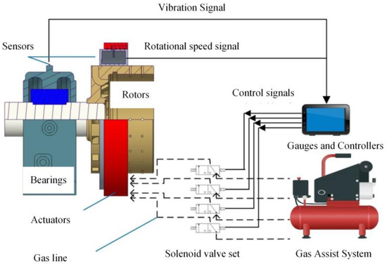
Figure 1.
Composition of the PLOABS system.
The working principle is briefly described as follows: the rotor’s operating status is monitored by the sensor in real time, and if the unbalanced vibration of the rotor does not exceed the preset value of the controller, then no operation is performed and monitoring continues. When the sensor detects that the unbalance vibration of the rotor exceeds the preset value of the controller, the controller quickly calculates the value and phase of the initial unbalance and the corrective vector that needs to be formed by the actuator counterweight disk, and outputs a control signal to control the on/off of the solenoid valve set. The compressed gas supplied by the gas assist system systematically pressurizes the reservoir chamber of the actuator along the line in accordance with the on/off of the solenoid valve set. The compressed gas drives the balance fluid reserved in advance in the actuator chamber to transfer in accordance with the results calculated by the gauge, which redistributes the mass on the reservoir disk and produces an equilibrium vector of equal magnitude and opposite direction to the unbalance vector, restoring the vibration to a defined level. When the unbalance amplitude of the rotor is reduced to the set value, the balancing actuator stops working until the unbalance vibration of the rotor again exceeds the preset value of the measuring and control device.
Compared with the liquid-filled online automatic balancing products, the PLOABS system has no liquid splash during the action, and after the rotor is stopped, the liquid in the storage chamber will not flow back, and the previous balancing state can be maintained after the machine is started again. It not only has the advantages of simple structure and large balancing capacity of liquid-injected online automatic balancing actuator, but also the balance fluid is transferred in a closed environment during the balancing process (no loss of balance fluid), the balancing process is reversible and the balancing capacity is durable, which is especially suitable for large rotating equipment rotor systems and other occasions with high requirements on working environment and balancing capacity.
The structure of the actuator and the way to achieve unbalanced mass compensation are fundamental to the realization of the PLOABS system and determine the performance and reliability of the system. As shown in Figure 2, the PLOABS actuator consists of two parts: the stator and the automatic balancing disc. In this, the automatic balance plate rotates synchronously with the rotor, including the liquid storage plate, the middle sleeve, the connecting pipe and the auxiliary tightening parts. The reservoir tray is evenly divided into four reservoir chambers by the partitions. In order to ensure that the equilibrium fluid in the reservoir can be transferred through the connecting tube and will not leak to the outside of the actuator, during the operation of the actuator, a gas injection tube is welded along the radial direction inside each storage chamber, and there are holes on both sides of the gas injection tube to connect with the inside of the storage chamber. Four air inlet recesses on the outer side wall of the intermediate sleeve correspond to the four reservoir chambers and are connected to the air injection tube.
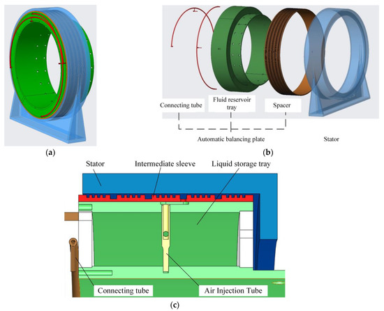
Figure 2.
Actuator structure. (a) Pneumatic–liquid automatic balance system. (b) Exploded view of actuator. (c) Schematic diagram of the assembly relationship of each part of the actuator.
There are labyrinth seals between adjacent inlet recesses, and the assembly clearance between the stator and the intermediate sleeve is small, so the gas ring can be formed by inlet recesses, which can maintain a stable inlet pressure and realize the dynamic and static transfer of compressed gas. The connecting tube is axially welded to the reservoir tray and connects the two chambers that are opposite to each other in the tray. In order to prevent the balance fluid in the reservoir tray from being transferred by centrifugal force when the actuator is not operating, the connecting pipe is bent into a semi-ellipse with a small straight pipe in the middle directly connected to the atmosphere. When the rotor is running normally, but the actuator is not working, the pressure on both sides of the straight pipe position in the middle of the connecting pipe is zero. That is, there is no pressure difference between the liquid in the two storage cavities connected by the connecting tube, and the balancing liquid in the cavity will not be connected. The straight pipe again serves to cushion the gas pressure when the actuator is working.
2.2. Working Principle of Pneumatic–liquid On-Line Automatic Balance System
2.2.1. Actuator Balancing Mechanism
According to the theory of rotor dynamic balance, it is known that the differential equation for the rotor system vibration is as follows.
The unbalanced forces generated by the unbalanced mass distribution during the operation of the rotor are as follows.
Among them, the unbalanced mass is and the unbalanced mass is at a radius of . From Equations (1) and (2), we can solve for the rotor amplitude caused by the unbalanced excitation force is as follows.
The reservoir disk of the actuator rotates synchronously with the rotor, and due to the centrifugal force, the balance fluid reserved in the reservoir cavity eventually forms a ring along the inner wall as shown in Figure 3.
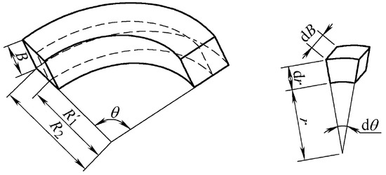
Figure 3.
Liquid distribution in the reservoir chamber.
So, the element volume of the liquid ring is as follows.
The volume size of the liquid ring is obtained by integrating the above equation.
Let the equilibrium liquid density be , so the centrifugal force corresponding to the liquid ring is shown in the following equation.
As shown in Figure 4, when the combined unbalanced mass force of is generated, the compressed gas drives the balancing liquid of mass from chamber B to chamber D, at the same time the equilibrium liquid of mass is transferred from chamber C to chamber A. Along the horizontal direction, the synthetic force formed by cavities B and D is shown in the following equation.
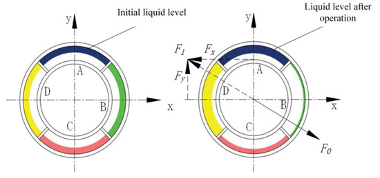
Figure 4.
Schematic diagram of the actuator balancing principle.
By the same method, it is possible to find . The magnitude of the balancing compensation force is shown in the following equation.
After balancing, the differential equation of vibration of the rotor is shown in the following equation.
Among them, is the mass of the automatic balancing disc, the automatic balancing actuator is driven by compressed gas to transfer the balance fluid in the reservoir tray to each other, forming a balancing compensation force to balance the initial unbalance force and achieve dynamic balancing.
2.2.2. Actuator Balance Performance
As the key part of the automatic balancing system, the balancing capacity and balancing accuracy of the actuator are important indicators to evaluate the goodness of the automatic balancing system.
A schematic diagram for calculating the balancing capacity of the actuator is shown in Figure 5, the centrifugal force generated by each micrometeoroid is , each can be decomposed into two component forces. One of the components is a component symmetrically parallel to the reservoir cavity and the other is a component perpendicular to the line of symmetry of the reservoir cavity. As the reservoir cavity is a symmetrical structure, the component forces perpendicular to the line of symmetry of the reservoir cavity cancel each other out. Therefore, only the partial force , which is symmetrically parallel to the reservoir cavity, remains. After integrating it, the magnitude of the liquid ring balance vector is as shown in the following equation.
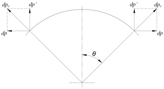
Figure 5.
Schematic diagram of centrifugal force.
During balancing process of the PLOABS system, the delay time of the controller output command, the opening and closing time of the solenoid valve, the transfer speed of the balancing liquid and the lag time in the gas transfer process have an impact on the balancing accuracy of the PLOABS system. The minimum mass of fluid to be transferred to the actuator for each gas injection can be expressed as the following equation (the meaning of s is the cross-sectional area of the connecting pipe, and t is the minimum time of each gas injection.).
In summary, for the structural design of the PLOABS actuator, the automatic balancing capacity is related to the radial thickness and axial length of the reservoir chamber; the automatic balancing accuracy is related to the cross-sectional area of the connecting tube and the delay time of the control system. For the choice of balance fluid, the balancing capacity of the actuator is proportional to the density of the balance fluid, and when the balance fluid is selected with a greater density of fluorine oil, etc., its balancing capacity increases linearly. The actuator balancing accuracy is directly proportional to the viscosity of the balance fluid, and the balancing accuracy grows when a more viscous oil is chosen for the balance fluid.
3. Actuator Performance Simulation Study
The pneumatic-hydraulic balancing actuator works essentially by injecting compressed gas to drive the transfer of quantitative balance fluid between opposing reservoir chambers. The two pairs of reservoir cavities are vector synthesized to obtain a compensation vector of equal magnitude and opposite direction to the unbalanced mass. Therefore, based on the fluent module of ANSYS Workbench, two flow fields inside the balancing actuator were simulated. In order to investigate the transfer of gas driving force and the transfer of balancing liquid, the gas flow field of the gas entering the storage chamber from outside through the inlet pipe and labyrinth seal and gas-driving balancing liquid in the relative cavity transfer of the gas–liquid flow field was simulated and analyzed.
3.1. Gas Drive Force Transfer Simulation Analysis
According to the working principle of pneumatic–liquid automatic balance actuator, compressed air enters the fluid storage chamber of the actuator through the intake pipe and the labyrinth seal ring. Due to the influence of the structure of the labyrinth seal, the gas will leak from both sides of the labyrinth seal ring to the external atmosphere. Finally, the air injection tube on the liquid storage tray enters the liquid storage chamber to drive the liquid in the chamber to transfer to the opposite side of the liquid storage chamber through the connecting tube. The following will explore the transfer of external high-pressure gas injection into the interior of the actuator chamber in terms of performance.
As shown in Figure 6, compressed gas enters the actuator interior through the stator inlet tube, each stator inlet tube corresponds to a set of labyrinth seal recesses machined at the stator and the intermediate sleeve gap position and a gas injection tube on the reservoir tray. When establishing the internal flow field of the actuator, only one stator inlet tube, one set of labyrinth seal recesses, one air injection tube, one reservoir cavity and the opposite reservoir cavity connected with it through a connecting tube are extracted and analyzed and calculated by 1/4 flow field.
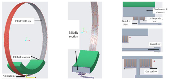
Figure 6.
Computational fluid domain.
After creating the above fluid calculation model, the fluid calculation model is imported into Meshing for boundary naming and meshing. The stator intake tube inlet is named inlet, and both sides of the 1/4 labyrinth seal are named outlet1 and outlet2, respectively. Furthermore, to improve the simulation efficiency, the mesh division is transformed into a polyhedral mesh afterwards, as shown in Figure 7.

Figure 7.
Boundary naming and meshing.
The solving module adopts the standard K-ε model which is commonly used in multiphase flow simulation, the stator inlet pipe is set as a pressure inlet and the inlet pressure is 1 MPa; both sides of the labyrinth seal are set up as pressure outlets with atmospheric pressure. After convergence of the calculation results, the gas pressure nephogram in the actuator reservoir can be obtained as shown in Figure 8. Intermediate sections are created to observe the pressure transfer from the outside gas into the actuator chamber. At the same time, the air pressure in the reservoir chamber at steady state is 0.47 MPa by the probe tool, and the efficiency of the drive force transfer under the current actuator structure design is known to be 47%.

Figure 8.
Fluid domain model and pressure distribution nephograms of intermediate sections.
Under actual working conditions, as a result of manufacturing and processing errors, etc., the gas pressure in the reservoir chamber, named gas driving force, may not meet the requirements of liquid transfer in the reservoir chamber. Therefore, the stator inlet tube cross−sectional area is considered to be increased to obtain higher and more stable gas driving force and higher gas transfer efficiency. The current cross−sectional diameter of the actuator stator inlet pipe is 5 mm and the cross−sectional area is 19.635 mm2. Now, the stator intake tube cross section is changed from circular to elliptical as shown in Figure 9, and the cross−sectional area is increased to 39.635 and 59.635 mm2. The steady-state pressures in the reservoir chamber corresponding to different inlet pipe cross−sections are obtained as shown in Figure 10a,b. By collating the relevant data, the effect of intake tube cross−sectional area on gas driving force can be obtained, as shown in Table 1.

Figure 9.
Change of air inlet pipe cross section. (a) Inlet pipe circular section. (b) Inlet pipe oval section.

Figure 10.
Influence of two sections of the inlet pipe on the gs driving force. (a) Inlet pipe circular section. (b) Inlet pipe oval section.

Table 1.
Variation of gas driving force with intake tube cross section.
From the results of the above analysis, the following conclusions can be drawn:
- (1)
- Extracting the gas flow field inside the actuator, the pressure distribution nephogram when the external gas enters the reservoir chamber was obtained by Fluent analysis. When the stator inlet pipe diameter is initially designed to 5 mm, the internal pressure of the reservoir cavity can reach 0.47 MPa and the transmission efficiency of the driving force is 47%; and
- (2)
- The correspondence between the gas driving force and the cross-sectional area and equivalent diameter of the gas pipe was obtained, and it was obvious that the elliptical pipe cross-section is conducive to increasing the transmission efficiency of the gas driving force, which provides reference for the subsequent structural design of the stator inlet pipe part of the actuator. Furthermore, the intake pipe cross-sectional area can be considered to be appropriately increased to optimize the actuator intake effect.
3.2. Equilibrium Fluid Transfer Simulation Analysis
According to the working principle of the balancing actuator, the compressed gas enters the reservoir cavity to drive the balance fluid to transfer in the relative cavity for the purpose of mass redistribution to achieve automatic balancing, so the fluid domain of the gas–liquid flow field mainly includes: connecting pipe, gas injection pipe and reservoir cavity. The actuator balancing process is essentially a transfer of balance fluid between two pairs of opposing chambers, thus a simplified fluid domain can be extracted from a pair of opposing cavities and the connected connecting tubes. When the balancing actuator is operating, the balance fluid can be predicted to show a ring-like distribution against the outer wall due to the centrifugal force at high speed. The extracted fluid domain is combined by cutting in Solidworks and the air domain near the inner wall on both sides and the fluid domain near the outer wall and connected through the connecting tube can be obtained, as shown in Figure 11b. The model was imported in the Fluent module of ANSYS Workbench, and the rotating conditions were applied to obtain a stable gas–liquid two-phase nephogram diagram, as shown in Figure 11c. Therefore, in order to effectively reduce the computational process of the simulation software, the analysis can be made directly from the formed stable gas–liquid flow field in the rotating state. In performing the simulation of equilibrium fluid transfer, two-phase fluid domain whose compressed gas and equilibrium fluid are distributed in a circular pattern along the radius is considered as the initial state.

Figure 11.
Grid division diagram. (a) Gas–liquid flow field inside the actuator. (b) Gas–liquid fluid domain modeling. (c) Gas–liquid two-phase nephogram diagram.
At the same time, according to the balance liquid transfer principle of pneumatic–liquid automatic balance actuator: during the whole transfer process, the gas pressure and liquid pressure on the drive side are positive pressures. The effect of centrifugal force is divided into two parts: assuming the minimum radius of the center of the connecting tube is the boundary, before the equilibrium fluid reaches the minimum radius of the center of the connecting tube, the centrifugal pressure is negative and impedes the flow of equilibrium fluid; after the equilibrium fluid flows through the minimum radius of the center of the connecting tube, the centrifugal pressure shifts to positive pressure, and drives the flow of the equilibrium fluid to the counter chamber. Therefore, based on the above analysis, if the balance fluid flows smoothly through the center of the connecting tube, it can be transferred to reach the opposite chamber and form a continuous flow. For the consideration of computer running time, the reservoir cavity and half of the connecting tube can be chosen as the fluid domain model, and the pressure inlet in the simulation analysis will be set as the inner wall of the sector cavity, and the pressure outlet was set to the center section of the connecting tube to speed up the simulation of the equilibrium fluid transfer.
Simulating the equilibrium fluid driven by the gas process, the simplified model is imported into Fluent, meshed in Meshing, check the mesh through the mesh quality module in “Meshing”, find the primary standard to judge the quality of the mesh “skewness”, the more the value tends to 0, it means the better the quality of the mesh. The boundary conditions and cell area conditions are set in Setup pre-processing, the number of time steps and time step length are set in iterative calculation, and the gas–liquid phase flow process is obtained after transient analysis, in which the two-phase nephogram diagrams of several phases are shown below. The time step is usually set at 10−6 s, because only when the time step is small enough, the calculation result will converge, and the residual curve will decrease by three orders of magnitude. When the result converges, the step size can be increased by one order of magnitude to test again. Or, use Courant Number to estimate the time step. If the calculation result diverges, reduce the time step again for calculation.
From the Figure 12 to analyze the two-phase flow process, because the connecting tube is elliptical and the outlet is in the lower right corner, the liquid in the cavity first changes in the upper left corner under the action of the pressure difference between the inlet and outlet and the pressure difference between the inside and outside of the reservoir chamber, under the action of the pressure difference between the inlet and outlet and the inside and outside of the reservoir chamber, and the lower right corner is less affected by the pressure difference. The lower right corner is less affected by the pressure difference. Due to gravity and the direction of rotation speed, the liquid in the upper left flows out first, while the liquid in the cavity accumulates in the lower part of the cavity, and then with the pressure difference, the volume slowly decreases and flows out through the connecting tube along the outer wall surface.
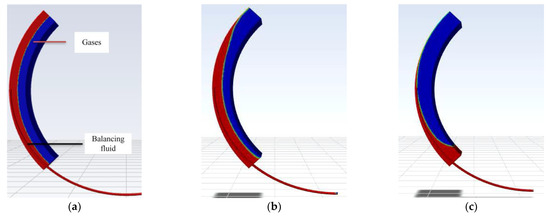
Figure 12.
Nephogram process for single-cavity transient analysis with connecting tubes. (a) Initial state of gas–liquid homogeneous distribution. (b) Gas–liquid two-phase change. (c) Gas–liquid two-phase change.
According to the working principle, environmental conditions and structural design of the pneumatic–liquid automatic balance actuator, it is known that the reservoir chamber balance fluid driving process is mainly related to three factors: the speed of the reference system applied to rotating machinery is reflected in the conditions of the pre-processed cell area; high pressure gas supplied by the gas source distributor is mainly reflected in the pressure inlet setting of the boundary conditions in the pre-treatment; the radius of the connecting tube in structural optimization is related to physical parameters such as time and velocity flux of liquid transfer. Therefore, after the simulation of the rotating flow field for the 3D physical model, changing the working conditions settings: reference system speed, pressure inlet, outlet radius. For these three different conditions, a single-cavity rotating flow field with an initial state of gas–liquid homogeneity is simulated and analyzed, and the six variable working conditions can be obtained under the parameter curve graph, as shown below.
- (1)
- The inlet pressure was set to 0.1 Mpa, the outlet radius was unchanged, and the speed of the reference system was changed to 600, 1200, and 1800 rpm for three working conditions, respectively. The results after simulation calculation are shown in Figure 13.
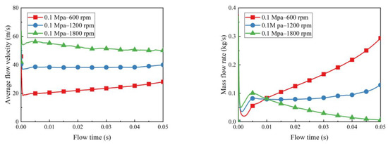 Figure 13. Variation of outlet average flow velocity at variable speed (left) and mass average flow velocity (right).
- (2)
- The speed of the reference system was 1200 rpm, the outlet radius was 3 mm, and the pressure inlet was set for three conditions, which were 0.1, 0.2, and 0.3 Mpa, and plots of the average flow velocity and mass flux at the exit surface with time were obtained. The results are shown in Figure 14.
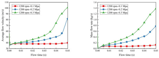 Figure 14. Variation of average flow velocity at variable pressure (left) and mass average flow velocity (right).
- (3)
- Assuming the inlet and outlet pressure was 0.1 Mpa and the speed of the reference system was 1200 rpm, the outlet radius was set to 3, 4 and 5 mm, respectively. After transient analysis of two-phase flow, average flow velocity and mass flux plots at the various outlet radius were obtained. The simulation results are shown in Figure 15.
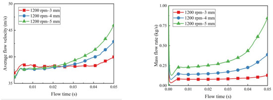 Figure 15. Variation of outlet average flow velocity at variable section (left) and mass average flow velocity (right).
From the above analysis, combined with the transient analysis of the two-phase nephogram diagram, for different sector models and connecting tubes, multiple working condition finite element simulations were performed, and the data reports were compiled and analyzed, and it can be concluded that:
- (1)
- At three different speed operating conditions, the trend of the rate of balancing liquid transfer with time is stable, which proves that the equilibrium device can complete the balance process stably at all three speeds. The flow direction of the two-phase flow is controlled by both gas pressure and rotational speed. The flow direction of the two-phase flow is controlled by both gas pressure and rotational speed. When the rotational speed increases, the rate of flow decreases and the balance fluid is more likely to be affected and remain in the chamber, slowing down the response to failure;
- (2)
- The average flow velocity and mass rate of flow increase with increasing inlet pressure. When the inlet pressure is low, the transfer speed is stable and the control accuracy is high; when the inlet pressure increases, the speed changes faster and the control accuracy decreases. Therefore, when controlling the balance fluid transfer, it is important to choose the appropriate pressure for a stable balance process; and
- (3)
- As the cross-sectional diameter of the connecting tube increases, there is a significant increase in average flow velocity and mass flux. In terms of flux, the larger the exit radius, the more significant the increase. However, due to the structural limitations of the actuator reservoir chamber itself, an excessively large radius of the connecting tube will cause the high-pressure gas phase to react more easily on it, and the gas entering the connecting tube is not conducive to the full transfer of liquid, so a reasonable size must be designed considering a combination of factors in future structural optimization.
4. Experimental Study of Pneumatic–liquid On-Line Automatic Balance System
4.1. Pneumatic–liquid On-Line Automatic Balance System
Based on the composition of the PLOABS system introduced in Section 2.1, the automatic balancing system as shown in Figure 16 is built. The actuator auto-balancing disk is mounted on the cantilever end of the rotor and rotates synchronously with the rotor. The actuator stator is bolted to the test stand base and has the assembly clearance of 0.3 mm from the auto-balancing disk. The sensors monitor the rotor’s operating status in real time, collecting information such as speed and vibration and sending it to the control cabinet, which analyzes the signals, determines the rotor’s operating status and sends control commands to the actuator. When the unbalanced vibration of the rotor is detected to exceed the preset value of the controller, the controller quickly calculates the magnitude and phase of the initial imbalance and the correction vector to be formed by the actuator counterweight disc, then the control signal is output to control the solenoid valve group to open, and the compressed gas enters the corresponding liquid storage cavity through the gas pipeline to drive the transfer of the balance liquid in the cavity to redistribute the mass of the actuator and produce a balance vector of equal size and opposite direction to the imbalance, finally, the vibration amplitude of the rotor returns to a limited level.
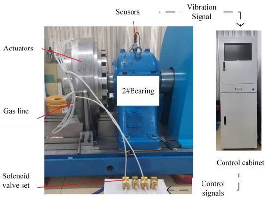
Figure 16.
Building an automatic balancing system.
4.2. Actuator Performance Testing
4.2.1. Actuator Static Performance Test
The key to the actuator’s ability to function is the ability of the fluid to transfer along the connecting tube, so the focus needs to be on whether sufficient gas drive can be provided by the gas assist system during the actuator’s operation. However, in practice, the actuator rotates synchronously with the rotor and it is not possible to measure the gas pressure in the reservoir chamber. Therefore, the actual static pressure of the actuator needs to be calibrated by measuring the gas pressure in the reservoir chamber without rotating the rotor. The actual minimum gas driving force of the actuator is obtained by analogy with the analysis of the actual static and dynamic gas paths.
During the assembly process of the actuator, a uniform clearance of 0.3 mm between the spacer and the stator was maintained, and the stator inlet tube was ensured to be facing the reservoir chamber injection tube inlet during the experiment. According to Chapter 3, two cross-sectional air injection tubes were designed as in Figure 17, and the local clearance was adjusted using a 0.1 mm copper piece. Analyzing the effect of different inlet pipe cross-sectional area and sealing gap on the gas driving force, the actual measured actuator static pressure is shown in Table 2 and Figure 18.
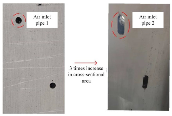
Figure 17.
Intake pipe section.

Table 2.
Static pressure for multiple working conditions.
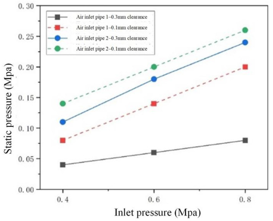
Figure 18.
Measured static pressure.
Combined with the simulation results in the previous section, the following conclusions can be drawn:
- (1)
- By simulation, the intake tube cross-sectional area is tripled and the intake efficiency is doubled in dynamic time. In the actual static test, under the same sealing gap, the air intake efficiency using intake tube 2 is nearly twice that of intake tube 1, which is comparable to the simulation results; and
- (2)
- The actual obtained static pressure, which can be considered as the minimum of the dynamic gas driving force. The actual assembly gap is about 0.3 mm, and the preliminary test ensures that the pressure in the cavity reaches 0.1 MPa or more, so it is more reasonable to choose the air inlet pipe 2.
4.2.2. Actuator Dynamic Performance Test
The static test ensures that the gas pressure in the actuator can reach 0.1 MPa or more, and it meets the requirements of the gas drive force for the initial test within 1500 rpm. To verify whether the liquid in the actuator can be transferred, an actuator dynamic performance test was conducted.
Dynamic testing was performed with actuator B and D reservoir chambers. Firstly, 600 mL of balancing fluid was injected into the B chamber, and the change in rotor amplitude during smooth operation of the rotor before and after gas injection was compared under the operating conditions of 0.8 MPa injection pressure and 600 rpm rotor speed.
Table 3 and Figure 19 show the change in amplitude of the four vibration measurement points of the rotor test stand after each air injection. Dynamic testing verified that the existing gas source conditions were able to provide the required gas drive for liquid transfer, demonstrating the rationality and availability of the actuator structure design.

Table 3.
Amplitude of each measurement point at 600 rpm.
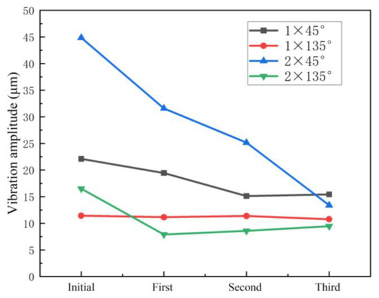
Figure 19.
Amplitude of each measurement point during dynamic test.
4.3. Automatic Balancing Test
After the testing of the actuator was completed, an automatic balancing test was conducted with the same amount of balancing fluid initially injected into each chamber and the experimental speed was 600 rpm. Taking the change in rotor amplitude before and after a certain automatic balancing system operation as an example, the amplitude variations of the bearing positions are shown in Table 4 and Figure 20.

Table 4.
Variation of bearing position amplitude.
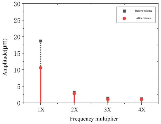
Figure 20.
Variation of vibration multiplier frequency at 2# bearing.
Through the above test results, the PLOABS system can reduce the unbalance vibration of #2 bearing from 18.3 to 10.6 μm, which verifies the feasibility and effectiveness of this balancing system on large rotating equipment.
5. Summary
This paper is a study on the imbalance vibration suppression technology for rotors of large rotating equipment, the following conclusions were obtained:
- (1)
- The current status of research on dynamic balancing of large rotating equipment and the development direction of structural optimization design of liquid type automatic balancing actuator were summarized. For the application of automatic balancing of large rotating equipment, a PLOABS system was proposed, whose composition and working principle were introduced, and the theoretical analysis of balancing capacity and balancing accuracy was carried out;
- (2)
- The actuator internal gas flow field model was established, which was analyzed to obtain the actuator internal flow field characteristics, and the model stator inlet pipe parameters were adjusted to obtain higher and more stable gas driving force. The actuator internal gas–liquid two-phase flow field model was established, which was analyzed to obtain the equilibrium liquid transfer characteristics under different working conditions, by adjusting the reference system speed, pressure inlet, outlet radius, providing reference for the subsequent actuator optimization design; and
- (3)
- Based on a large rotating equipment simulation test bench, the PLOABS system was built to test the static and dynamic performance of the actuator, in order to make the actuator meet the action requirements. Finally, the automatic balancing test was performed, and the system reduced the measured rotor amplitude from 18.3 to 10.6 um, which verified the feasibility and effectiveness of the improved automatic balancing system, and provided theoretical support and experimental verification for the subsequent structural innovation and engineering application of the actuator.
Author Contributions
Conceptualization, X.P. and D.G.; methodology, X.P. and D.G.; software and validation, D.G. and J.H.; formal analysis, W.L. and J.H.; investigation, D.G. and W.L.; resources, W.L.; data curation, D.G.; writing—original draft preparation, D.G. and W.L.; writing—review and editing, X.P. and D.G.; visualization, X.P.; supervision, X.P.; project administration, X.P.; funding acquisition, X.P. All authors have read and agreed to the published version of the manuscript.
Funding
This research was funded by National Natural Science Foundation of China (Grant No. 51875031) and Beijing Natural Science Foundation (Grant No. 3212010).
Data Availability Statement
Not applicable.
Acknowledgments
The authors sincerely thanks to National Natural Science Foundation of China (NSFC) and Beijing Natural Science Foundation for funding and Beijing University of Chemical Technology (BUCT) for providing us with a good platform.
Conflicts of Interest
The authors declare no conflict of interest. The funders had no role in the design of the study; in the collection, analyses, or interpretation of data; in the writing of the manuscript, or in the decision to publish the results.
References
- Tong, Z.T.; Yang, X.M.; Shang, P.X.; Ma, J.Y.; Zhang, Y.; Zhang, C. Effect of Inlet Condition on the Performance Curve of a 10 MW Supercritical Carbon Dioxide Centrifugal Compressor. Machines 2022, 10, 359. [Google Scholar] [CrossRef]
- Tuerxun, W.; Xu, C.; Haderbieke, M.; Guo, L.; Cheng, Z.M. A Wind Turbine Fault Classification Model Using Broad Learning System Optimized by Improved Pelican Optimization Algorithm. Machines 2022, 10, 407. [Google Scholar] [CrossRef]
- Jalayer, M.; Kaboli, A.; Orsenigo, C.; Vercellis, C. Fault Detection and Diagnosis with Imbalanced and Noisy Data: A Hybrid Framework for Rotating Machinery. Machines 2022, 10, 237. [Google Scholar] [CrossRef]
- Jin, X.; Liu, Y. Numerical and Experimental Analysis for the Dynamics of Flawed-Machining Rod-Disk Rotor with Inner Misalignment. Machines 2022, 10, 355. [Google Scholar] [CrossRef]
- Ranjan, G.; Tiwari, R. Application of active magnetic bearings for in situ flexible rotor residual balancing using a novel generalized influence coefficient method. Inverse Probl. Sci. Eng. 2019, 27, 943–968. [Google Scholar] [CrossRef]
- Xu, X.; Fan, P.P. Rigid Rotor Dynamic Balancing by Two-plane Correction with the Influence Coefficient Method. In Applied Mechanics and Materials; Trans Tech Publications Ltd.: Wallerau, Switzeland, 2013; Volume 365, pp. 211–215. [Google Scholar]
- Quartarone, C.; Beqari, J.; Detoni, J.G.; Cometti, F.; Emelli, E. Balancing of Turbomolecular Pumps: Modal Balancing Approach and Experimental Results. In Proceedings of the 10th International Conference on Rotor Dynamics—IFToMM; Springer: Cham, Switzereland, 2019; Volume 4, pp. 119–128. [Google Scholar]
- Bin, G.F.; He, L.D.; Gao, J.J.; Li, L.B. High-speed dynamic balancing method for low pressure rotor of a large steam turbine based on modal shape analysis. J. Sound Vib. 2013, 32, 87–92. [Google Scholar] [CrossRef]
- Zhang, Y.; Li, M.; Yao, H.Z.; Gou, Y.J.; Wang, X.Y. A modal-based balancing method for a high-speed rotor without trial weights. Mech. Sci. 2021, 12, 85–96. [Google Scholar] [CrossRef]
- Liu, S. A modified low-speed balancing method for flexible rotors based on holospectrum. Mech. Syst. Signal Process. 2007, 21, 348–364. [Google Scholar] [CrossRef]
- Hao, C.Z.; Du, J.R.; Liang, H.R. Imbalanced Fault Diagnosis of Rolling Bearing Using Data Synthesis Based on Multi-Resolution Fusion Generative Adversarial Networks. Machines 2022, 10, 295. [Google Scholar] [CrossRef]
- Fan, H.W.; Jing, M.Q.; Wang, R.C.; Liu, H.; Zhi, J.J. New electromagnetic ring balancer for active imbalance compensation of rotating machinery. J. Sound Vib. 2014, 333, 3837–3858. [Google Scholar] [CrossRef]
- Zachwieja, J.; Jarzyna, T. Dynamic Balancing of a Horizontal Rotor with a Cracked Shaft. In Scientific Session on Applied Mechanics X; AIP Publishing: Melville, NY, USA, 2019. [Google Scholar]
- Su, N.Q.; Li, X.; Zhang, Q.H. Fault Diagnosis of Rotating Machinery Based on Wavelet Domain Denoising and Metric Distance. IEEE Access 2019, 7, 73262–73270. [Google Scholar] [CrossRef]
- Li, K.X.; Peng, C.; Deng, Z.Q.; Huang, W.; Zhang, Z.M. Field dynamic balancing for active magnetic bearings supporting rigid rotor shaft based on extended state observer. Mech. Syst. Signal Process. 2021, 158, 107801. [Google Scholar] [CrossRef]
- Pan, X.; Lu, J.Q.; Huo, J.J.; Gao, J.J.; Wu, H.Q. A Review on Self-Recovery Regulation (SR) Technique for Unbalance Vibration of High-End Equipment. Chin. J. Mech. Eng. 2020, 33, 89. [Google Scholar] [CrossRef]
- Shin, K.K.; Ni, J. Adaptive control of active balancing systems for speed-varying rotors using feedforward gain adaptation technique. J. Dyn. Syst. Meas. Control.-Trans. Asme 2001, 123, 346–352. [Google Scholar] [CrossRef]
- Pan, X.; He, X.T.; Wu, H.Q.; Ju, C.L.; Jiang, Z.N.; Gao, J.J. Optimal Design of Novel Electromagnetic-Ring Active Balancing Actuator with Radial Excitation. Chin. J. Mech. Eng. 2021, 34, 9. [Google Scholar] [CrossRef]
- Pan, X.; Xie, Z.; Lu, J.; Wu, H.Q.; Gao, J.J.; Jiang, Z.N. Novel Liquid Transfer Active Balancing System for Hollow Rotors of High-Speed Rotating Machinery. Appl. Sci. 2019, 9, 833. [Google Scholar] [CrossRef]
- Pan, X.; Gao, J.J. Research on the principle and method of pneumatic liquid and electromagnetic slip ring automatic balancing for high-end Machine Tools. J. Mech. Eng. 2017, 53, 183. [Google Scholar]
- Rumin, R.; Bergander, M.; Cieslik, J.; Kulpa, M. Extended Active Vibration Control for Wind Turbines. In Proceedings of the 2017 XIIIth International Conference on Perspective Technologies and Methods in Mems Design (MEMSTECH), Lviv, Ukraine, 20–23 April 2017; pp. 38–40. [Google Scholar]
- Yun, X.L.; Mei, X.S.; Jiang, G.D.; Hu, Z.B.; Zhang, Z.H. Investigation on a No Trial Weight Spray Online Dynamic Balancer. Shock Vib. 2018, 2018, 7021215. [Google Scholar] [CrossRef]
- Pan, X.; Wu, H.Q.; Gao, J.J. Pneumatic Liquid Transfer Type Active Balance System for Shaft Mounting. CN106090120B, 7 September 2018. [Google Scholar]
- Pan, X.; Wu, H.Q.; Gao, J.J. Control strategy and experiment research on liquid-transfer active balancing device by pneumatic means for grinding machines. J. Vib. Shock 2015, 34, 1–5. [Google Scholar] [CrossRef]
Publisher’s Note: MDPI stays neutral with regard to jurisdictional claims in published maps and institutional affiliations. |
© 2022 by the authors. Licensee MDPI, Basel, Switzerland. This article is an open access article distributed under the terms and conditions of the Creative Commons Attribution (CC BY) license (https://creativecommons.org/licenses/by/4.0/).


