Abstract
The position accuracy of the bottom dead centre (BDC) of a slider is a crucial performance index to measure the quality of a multi-link mechanical press. At present, the research on improving the position accuracy of the BDC mainly focuses on error compensation, and there is a lack of research on the tolerance design of the transmission mechanism according to the accuracy requirements of the BDC. In this paper, the motion output accuracy of the press is characterized by the position error of the BDC of the slider and the inclined angle error of the slider. Based on the loop increment method, the error transmission model of the transmission mechanism of a multi-link mechanical press was established. The key error factors that affect the output accuracy of the press were determined by analysis of error sensitivity. On this basis, a precision synthesis method considering manufacturing cost and BDC precision reliability was proposed. Finally, a Monte Carlo simulation and experiments on a toggle mechanical press were conducted to verify the model. The results show that the proposed error model and optimization method are feasible and effective.
1. Introduction
Compared with the traditional crank press, multi-link presses, such as elbow bar presses, have the characteristics of good quick return, high forming accuracy, and strong bearing capacity [1]. The motion accuracy of the slider is one of the important indexes to evaluate the performance of the press. Under the background of near net shape [2], the requirements for the product quality of the press are increasing, and there is an urgent need to improve its accuracy performance. The design of ultraprecision machines and the research of related key technologies become particularly important to achieve rapid and economic production [3]. The improvement and guarantee of the motion accuracy of the slider is the key technology studied in the design and manufacture of the multi-link press [4]. Therefore, it is necessary to analyze the key factors affecting the accuracy of the press and reasonably allocate the accuracy parameters of each part from the perspective of saving the manufacturing cost of the press to meet the processing requirements of near net shape forming.
Establishing the mapping relationship between the geometric error source and the output error of the mechanism is the basis of accuracy synthesis, which has been studied by many scholars. In error modeling, common methods include homogeneous transformation matrixes [5,6], Denavit–Hartenberg (D–H) transformation matrixes [7], screw theory [8,9,10,11], and exponential product [12]. Wu et al. [13] established the geometric error model of the rotating axis based on the theory of multi-body dynamics and studied a prediction method of the comprehensive error field in the machining space of five-axis machine tools based on the S-shaped specimen family. Chen et al. [14] proposed a unified method for the accurate analysis of general planar three-legged parallel robots based on constrained planar motion generalized kinematic mapping. Tian et al. [15] extended the generalized Jacobian method to the error modeling of machine tools, which can divide the source error into two subsets related to the compensated and non-compensated pose accuracy. Zhao et al. [16] proposed an angle error analysis method for a planar synthetic aperture radar antenna multi-closed-loop deployment mechanism considering link deviation and joint clearance, which provides an effective tool for designers to evaluate its accuracy performance in the design stage. From the current research situation, most of the error modeling research was mainly aimed at error prediction and error compensation.
Accuracy synthesis is a structural optimization problem, is the inverse problem of accuracy analysis, and has more practical significance in engineering. A. K. Srivastava et al. [6] proposed a compact volumetric error model, which directly considers the inaccurate links and joint shapes and joint transformations using small angle approximation and then finds the total volume error in the workspace as a function of all possible errors. A. Chaker et al. [17] took five different non-over-constrained spherical parallel mechanisms (SPM) as the research object and analyzed the influence of the manufacturing error of the connecting rod on the position and orientation of its output end platform. The results show that different non-over-constrained versions of SPM have different pose accuracy. Tian et al. [15,18] applied the generalized Jacobian method to the error modeling of machine tools. They proposed a general and systematic method to divide the source error into two subsets related to the compensated and uncompensated pose accuracy so as to model the geometric error of machine tools. Chen et al. [19] took the dimensional tolerance unit and tolerance grade coefficient as the weighting coefficient; using the linear weighting method, the multi-objective optimization was transformed into a single objective optimization, and the mathematical model of the optimal dimensional tolerance and the fitting tolerance of the kinematic pair of the planar linkage mechanism was established. Jin et al. [20] proposed a tolerance design method in the early design stage of auto parts based on the Shapley value method (SVM) of joint game theory. P. K. Singh [21] and Krishna [22] used an optimization method to realize the simultaneous distribution and allocation of machine tool manufacturing tolerance and assembly tolerance based on the minimum manufacturing cost. Chen et al. [23] proposed a static accuracy design method based on global optimization and error sensitivity analysis, which transforms the static error allocation problem of machine tools into a multi-objective optimization problem with nonlinear constraints. Zhang et al. [24] proposed a precision design method for multi-axis CNC machine tools based on reliability theory. Cha et al. [25] proposed a robust optimization design method using the hybrid response surface method (H-RSM), which directly finds the best advantage to meet the target Z value or failure probability.
The previous literature shows that there is relatively little research on the mechanical press in the field of comprehensive precision research, and most of the research objects are lathes, milling machines, or machining centers. Among the many factors that affect the output accuracy of the press, the geometric dimension error of the transmission mechanism has a greater impact, as it leads to the lower dead center accuracy of the slider beyond the design range, affecting the forming quality of the workpiece and the service life of the die. Bai et al. [26,27] used the matrix analysis method to analyze a four-driven parallel press and concluded that the most significant factor affecting the accuracy of the press is the structural parameter error of the output branch chain. Lu Xinjian [28] derived the error transfer function equation of the rod length and fixed contact coordinates by using the differential method and compared the error transfer coefficient at the bottom dead center. Qian Huanan [29] established a comprehensive error model of the transmission link frame of the press by using the matrix method and the theory of multi-body systems.
Due to the complexity of multi-link mechanisms, the research on the motion error of multi-link mechanism is not mature enough at present, and there is still a big gap regarding the practical application. To solve the above problems, this paper uses the loop increment method to model the error of the transmission mechanism. On this basis, the error transmission model of the transmission mechanism of the multi-link mechanical press is established according to the principle of error-independent action so that the influence of the connecting rod and positioning error on the output accuracy of the press slider can be easily clarified. The key error influencing factors are determined through sensitivity analysis, and the accuracy of the transmission mechanism of the press is comprehensively optimized, considering the influence of the machining accuracy on the manufacturing cost.
2. Problem Description
A toggle transmission mechanism, as shown in Figure 1, is a typical mechanism of a multi-link mechanical press, which is commonly used in the cold and warm forging process. Multi-link cold and warm forging mechanical presses are the key equipment to realize the near net shape of cold and warm forging. The elbow bar transmission mechanism expands the stroke of the press and reduces the speed within the nominal stroke. The transmission mechanism is composed of two sets of toggle linkages, which are symmetrically distributed on both sides. The toggle linkage mechanism is composed of an eccentric gear, a toggle linkage, an upper rod, a bottom rod and a slider. During operation, the motor drives the eccentric gear to rotate at a constant speed at a certain angular speed through gear transmission. Through the multi-link transmission mechanism, it is finally transformed into the reciprocating motion output of the slider with quick return characteristics.
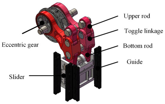
Figure 1.
The toggle transmission mechanism with slider.
The accuracy of the rod system determines the quality of forging and also affects the service life of the die. Since the toggle mechanical press is driven by an AC motor and flywheel instead of a servo motor, it is difficult to guarantee the position precision by popular closed-loop control. In an ideal case, the transmission mechanism composed of two sets of symmetrical rod systems needs to be consistent so that the slider can remain horizontal and perpendicular to the guide rail. However, due to the inevitable error defect of the rod length, the running curve of the rod system will inevitably deviate from the ideal situation, and the slider will also tilt. In other words, the accuracy of the bar system has a great impact on the dynamic performance of the press. Therefore, in order to analyze the accuracy of the transmission mechanism of the multi-link press, two problems need to be clarified: (1) how to calculate the output error of the linkage caused by the design and manufacturing deviation of the linkage and (2) when considering the manufacturing cost, how to determine the length tolerance of each member and the machining and positioning tolerance of the shaft hole.
3. Error Modeling
3.1. Configuration and Kinematic Chains
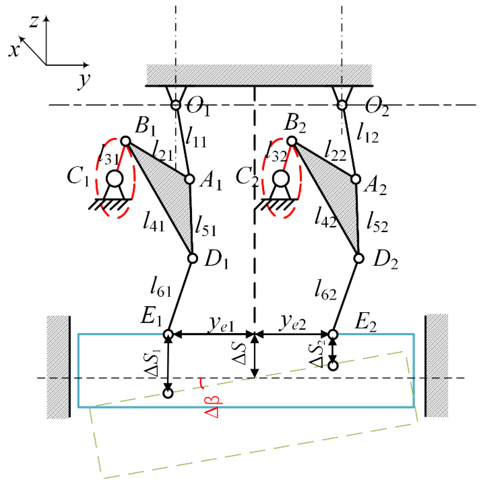
Taking the elbow bar mechanism which is driven by side crank as the research object, an error analysis of the transmission system is carried out. As shown in Figure 2, the transmission mechanism of this type of press is composed of two independent toggle mechanisms on the left and right, which are symmetrically arranged on the structure. The coordinate system Oyz was established on the vertical plane where the two upper fulcrums O1 and O2 are located. The coordinate system O1xz was established with the upper fulcrum O1 of the left link as the origin on the plane where the left link is located, and the coordinate system O2xz was established with the upper fulcrum of the right link as the origin on the plane where the right link is located.
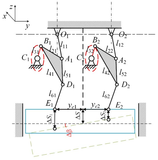
Figure 2.
Schematic of the toggle transmission mechanism.
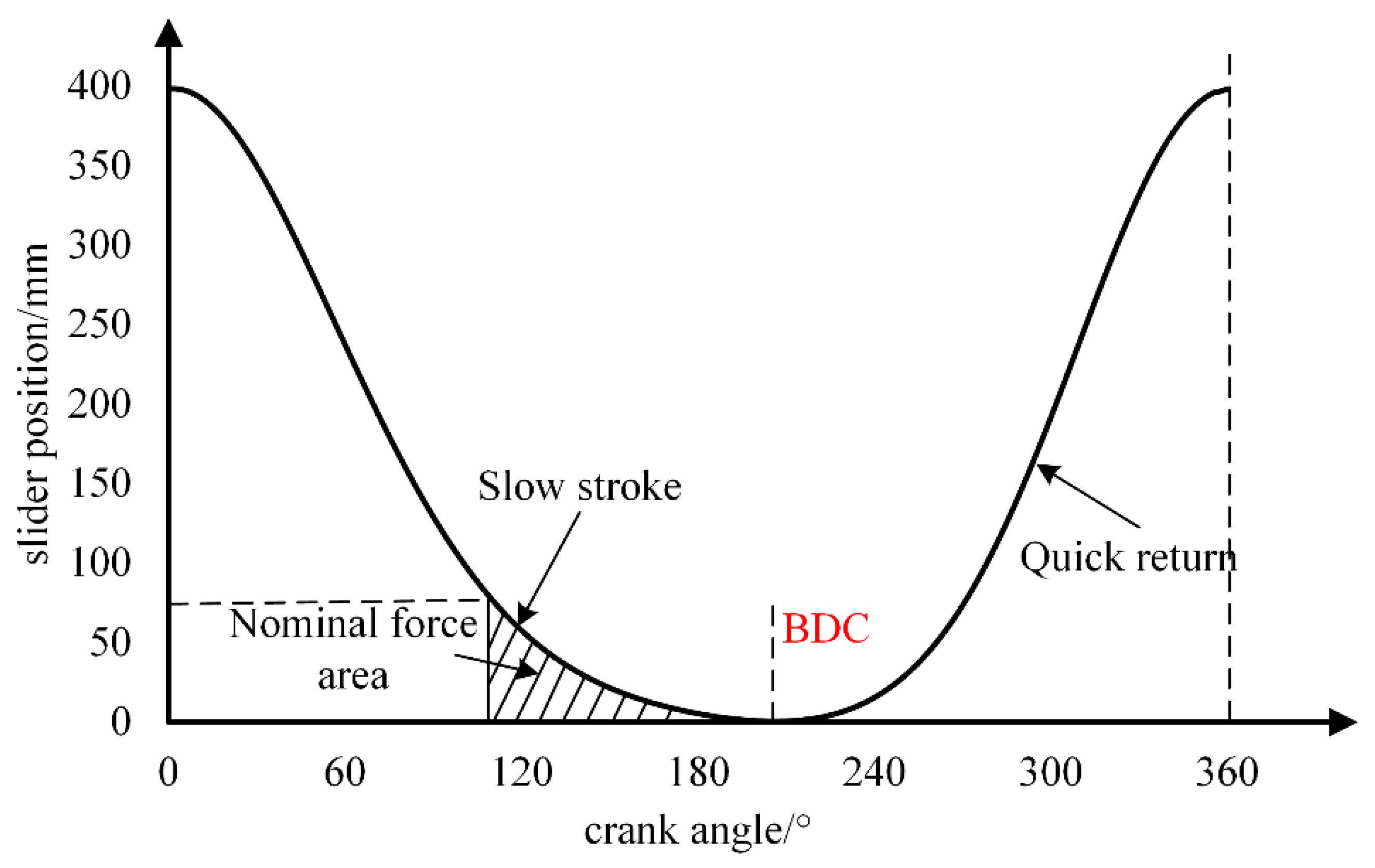
Due to manufacturing and positioning defects, there is a deviation between the actual motion posture and the ideal motion posture during the reciprocating motion of the press slider, which is called a mechanism error. The ideal motion curve of the slider is shown in Figure 3. The slider forms the workpiece during the downward stage near the bottom dead center (BDC) and then returns quickly. In order to better describe this error, the position error of slider BDC ΔS and inclined angle error Δβ are two indicators. The position error of the BDC of sliding blocks Δs1 and Δs2 can be obtained as the expressions of slider output position error and angle error are, respectively:

Figure 3.
Diagram of slider displacement curve.
Because the output error is smaller than the structural parameters, thus,
3.2. Geometric Error Elements
Due to the long kinematic chain of the toggle mechanism, there are many factors that affect the output accuracy of the slider of the multi-link mechanism. Thus, special attention should be paid at design time. The error sources mainly include manufacturing error of mechanism components, assembly and positioning error, clearance error of the rotating unit, driving error of the driving pair, error caused by elastic deformation, and thermal deformation caused by motion when subjected to heavy load. Because the servo motor is used as the driving source, it has high positioning accuracy, and the influence of input error can be ignored. When the assembly error is subject to the assembly process, the clearance error is difficult to eliminate. This paper mainly analyzes the influence of geometric errors of components (that is, the length error of members and the position error of shaft holes) on the motion accuracy of sliding blocks. Table 1 lists the structural parameters, corresponding error terms and variable symbols of the transmission mechanism of the press. Table 2 lists the position source errors of the transmission mechanism of the press and their variable symbols.

Table 1.
Linkage length error of press transmission mechanism.
Table 2.
Position source error of press transmission mechanism.
3.3. Error Modeling Based on Loop Increment Method
The loop increment method establishes the motion equation according to the vector form of the mechanism and regards the original error as a variable. We must obtain the differential of the equation of motion and replace the differential in incremental form. Using the form of vector or matrix to simplify, we can get a simple form of mechanism error equation or mechanism increment equation. A planar mechanism can generally be expressed as a closed planar polygon by vectors, so the relationship between its output position, angle and mechanism parameters and input can be expressed by the following vector equations:
If the vector is expressed by plural form, it can be expressed as:
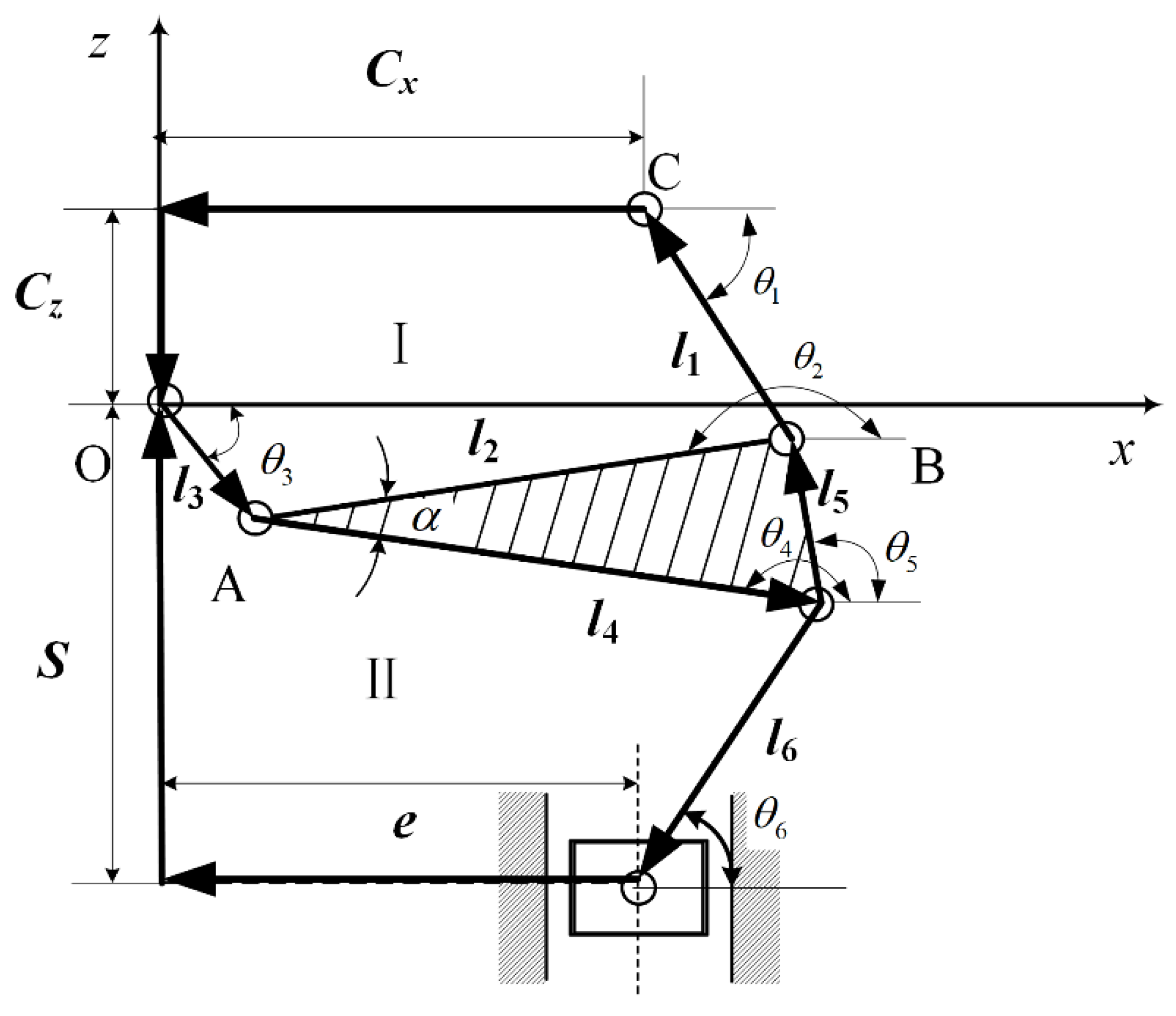
We take point O as the origin and establish the coordinate system. The vector diagram of the multi-link transmission mechanism is shown in Figure 4. The vector li represents the length of each linkage, and the whole mechanism is divided into two independent loops, I and II.

Figure 4.
Vector diagram of mechanism.
For the toggle mechanism, two-vector closed equations/position equations of the mechanism can be written as:
We write the vector as the plural form, where θi represents the angle between the ith vector and the x-axis.
Assuming that both li and θi are functions of time t, the derivative of time t is obtained. Both sides of the equation are multiplied by Δt at the same time to obtain the mechanism error equation in incremental form.
The error increment equations of the mechanism can be obtained.
Let θ = θ1; the variable Δθ1 can be eliminated. Note that since the triangular bar is a rigid body, Δθ4 = Δθ5, we can get
Δθ4 can be obtained
Let θ = θ6; the variable Δθ6 can be eliminated so as to obtain the linear relationship between Δθ6 and Δs.
The above formula can be rewritten into:
Solving Equations (14) and (16) simultaneously, Δθ4 can be eliminated.
This formula includes the influence of all the original errors of the mechanism on the position error of the output slider displacement of the mechanism.
Notice that , and there is
4. Key Error Identification Based on Sensitivity Analysis
Based on the above error model, the sensitivity analysis of the mechanism’s output error of each error source can be carried out, which will contribute to the accuracy design after the size optimization of the transmission mechanism. We can better understand the importance of each error, and these errors should be paid more attention to in the design.
The error sensitivity is used to reflect the influence of small changes in each error factor on the total output error. The error sensitivity is the absolute value of the sliding block motion output error on the partial derivative of each error factor. If the sensitivity of the i-th error Δi is ξi, then there is
In order to compare the influence degree of different error sources and highlight the main influencing factors, the error sources with significant influence can be determined. A statistical significance index can be used to measure the influence of a single structural parameter error under a finger positioning shape. In order to better identify and analyze the key error sources and normalize the sensitivity coefficients of the parameters of each error source, we can define
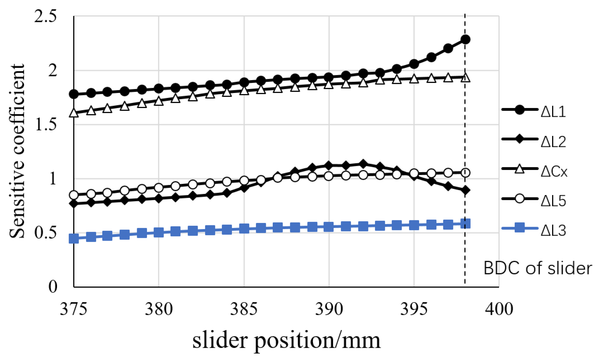
The structural parameters of the press (unit: mm) are: l1 = 575, l2 = 1697.5, l3 = 205, l4 = 1891, l5 = 585, l6 = 835, Cx = 1500, Cz = 570, e = −23. MATLAB is used for simulation and analysis, and the sensitivity of the forming area near the BDC of each error source to the position error of the slider is obtained. Sensitivity analysis can be used to guide the precision design of the press so as to provide a basis for controlling the error to a small extent in the design stage of the multi-link transmission mechanism. The sensitivity of the influence of the key parameter error on the slider output position error is shown in Figure 5. The sensitivity and significance of each geometric error source are shown in Table 3
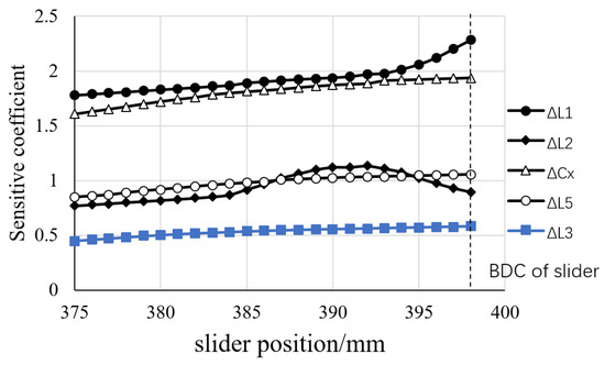
Figure 5.
Sensitivity of key error to slider position error.
Table 3.
Main error elements and their sensitivity and significance.
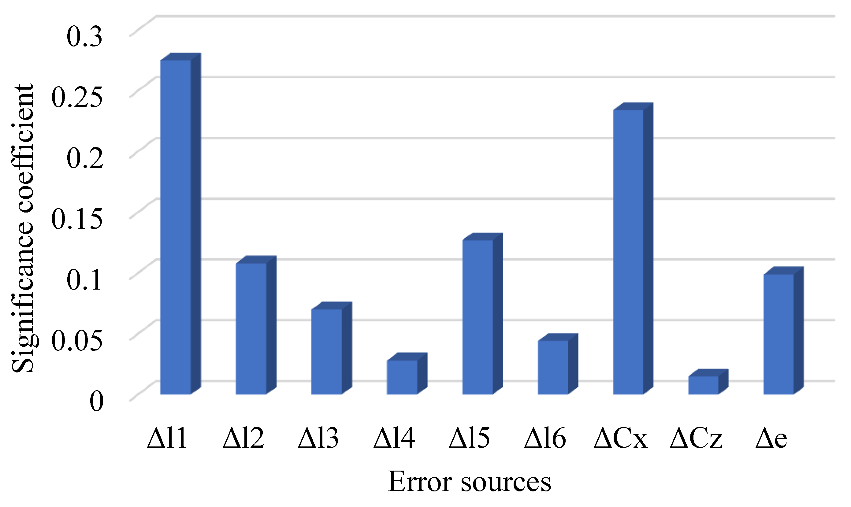
Figure 6 shows the significance comparison diagram of each error element corresponding to the slider position error. Through this mapping function, the mapping relationship between the 9 original errors of the transmission mechanism and the slider displacement error is established. It can be seen from the figure that each error source has different effects on the position error of the press slider. Through sensitivity analysis, it can be seen that the position error of the BDC of the slider showed a significant correlation with Δl1 and ΔCx, accounting for 51% of the impact of all error sources. ΔCz and Δl4 have little impact on the position error.
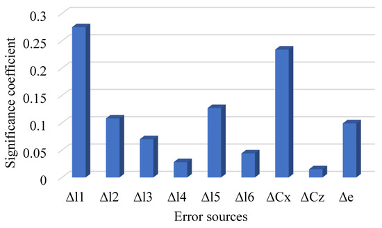
Figure 6.
Significance coefficient on the accuracy of the slider BDC.
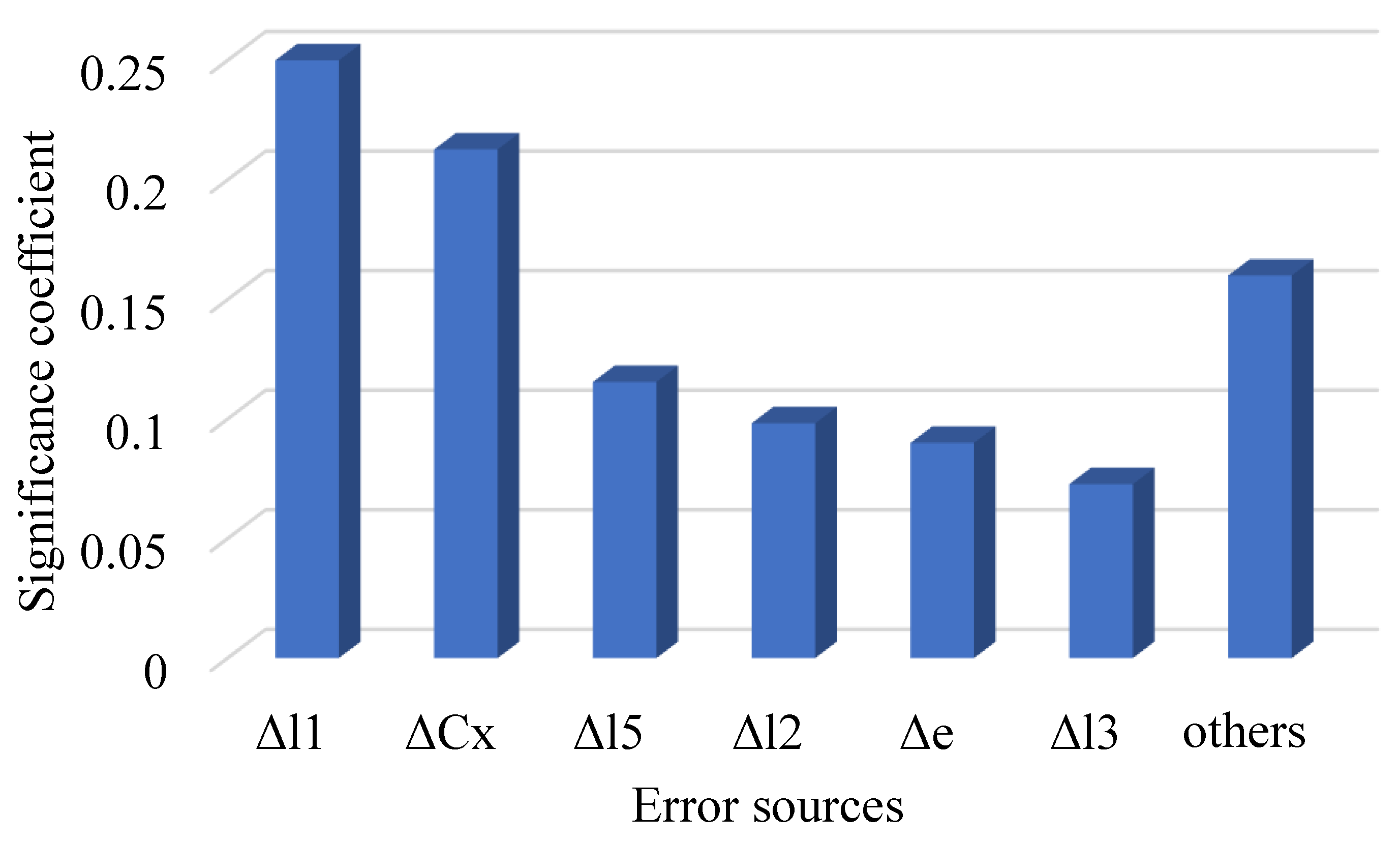
Similarly, the key error source parameters that have an important impact on the inclined angle error of the slider can be identified. The key error source of the slider tilt angle error at the bottom dead center position is the original error of 10 items. As shown in Figure 7, Δl1, ΔCx and Δl5 have a great effect on the error, with the influence on the error accounting for 85% of the influence degree of all error sources.

Figure 7.
Significance coefficient on the inclined angle error of the slider.
5. Tolerance Optimization Design
5.1. Optimization Model
The tolerance accuracy distribution of the transmission mechanism is used to determine the tolerance range of each component reasonably under the given accuracy requirements. Therefore, the design variables of the optimization problem are the geometric errors of each component, and the design variables are as follows:
The cost of dimensional tolerance mainly depends on the value of tolerance and the manufacturing process to obtain the tolerance. Generally, the larger the tolerance value, the lower the manufacturing cost. For the same tolerance, using different processing technology will also have different processing costs. Therefore, the manufacturing cost of the connecting rod parameter tolerance of the mechanism is a function of the width of the tolerance zone and the processing technology. According to the theory of mechanical manufacturing technology, the relative manufacturing cost of a single connecting rod can be obtained by [30]:
where ai is the tolerance characteristic index; Ki is the technological coefficient, which is the same for the same production process. In actual manufacturing, the smaller the manufacturing tolerance, the higher the production cost. Through investigation, the processing coefficient of the connecting rod is 8.25, and the position positioning process coefficient is 5.63 in order to obtain the characteristic index. For the same production process, the functional relationship between the relative cost and the sum can be obtained according to the empirical data. Therefore, the objective function of the transmission mechanism is
In order to make the press after precision design reach a certain level of accuracy, the main constraints of connecting rod parameter tolerance optimization are that the output position error of the slider BDC and the error of the tilt angle of the slider are less than the design expectation. The maximum allowable deviation of the slider position is taken as , and the reliability requirement is p1 = 90%. The maximum allowable deviation of the sliding block tilt angle is taken as , and the reliability requirement is p2 = 95%. When the probability that the required error is less than or equal to the given value Ri is greater than or equal to P, the constraint form is:
In order to facilitate the optimization calculation, the probability theory can be applied to deduce the above formula as a deterministic constraint. We order τ = (ωi − Ei)/σi, where Ei and σi represent the mean and standard deviation of error ωi, respectively. Constraints can be overridden to
For the standard normal distribution, there is
For a given probability level, the corresponding confidence limit of the normal distribution table difference can be passed. It can be obtained by comparing Equations (25) and (26), and the stochastic constraint can be transformed into a normalized deterministic constraint function
5.2. Optimization Results
Based on the above design variables, objective functions and constraints, an optimization design model is established, and an adaptive genetic algorithm is used for optimization. The control parameters of the genetic algorithm are set as follows: population size m = 100, crossover probability PE = 0.8, mutation probability = 0.05. The geometric dimensions of structural parameters of multiple connecting rods are the same as above, and the optimization results of tolerance allocation are shown in Table 4.
Table 4.
Results of the tolerance optimization.
5.3. Analysis of Results and Reliability Verification
The Monte Carlo simulation (MCS) method was used to evaluate the accuracy of the mechanism in order to estimate how much the pose error of the slider is reduced from the initial design by the proposed optimization method. MCS is a numerical calculation method that uses computer technology to generate random statistical sampling data and then solve the approximate solution of technical engineering problems.
The processing and positioning errors of each component obey the normal distribution, and the mean value of the component error was calculated according to the upper and lower deviations. According to the 3 σ principle, the mean square deviation of the error of component i is
We generated the random error source parameters of each component that obey the normal distribution and substituted the upper random parameters into the error model of the mechanism for analysis and calculation. After n iterations, the sample values of the output errors of the position accuracy of the lower dead center of the output slider and the accuracy of the tilt angle of the slider were obtained.
When the Monte Carlo method is used for reliability analysis, the sampling times are n = 500. We carried out a point evaluation on the reliability of the slider position and the tilt angle, respectively, and the evaluation results are shown in Table 5.
Table 5.
Comparison of errors before and after optimization.
After optimization, the reliability of the lower dead center position of the slider reached 91.26%, and the reliability of the tilt angle error of the slider was 98.72%. From the optimization results, it can be seen that the tolerance optimization method of the adaptive genetic algorithm used in this paper demonstrates a great improvement in the reliability of the output error before the optimal allocation. Under the condition that the output accuracy and robustness of the slider are greatly improved, the processing cost is greatly reduced.
5.4. Experimental Verification
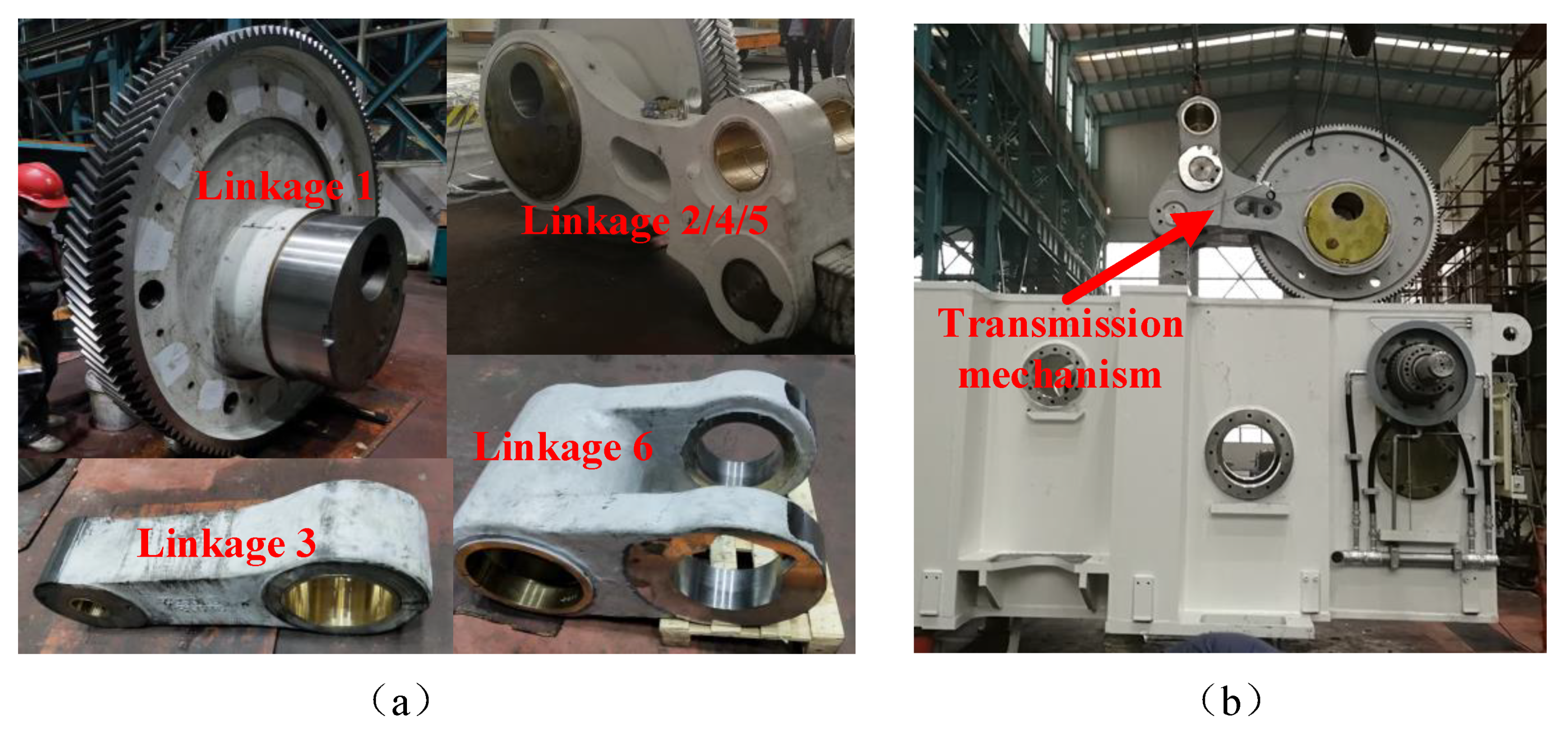
After completing the tolerance design of the transmission mechanism of the elbow bar press, the key components of the transmission mechanism are processed according to the above-optimized tolerance requirements, as shown in Figure 8a. After processing, we assembled the press according to the appropriate assembly sequence, and the process is shown in Figure 8b.
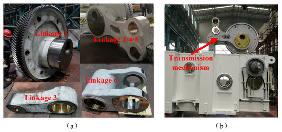
Figure 8.
Transmission mechanism components and assembly process. (a) Different linkage components (b) Assembly process.
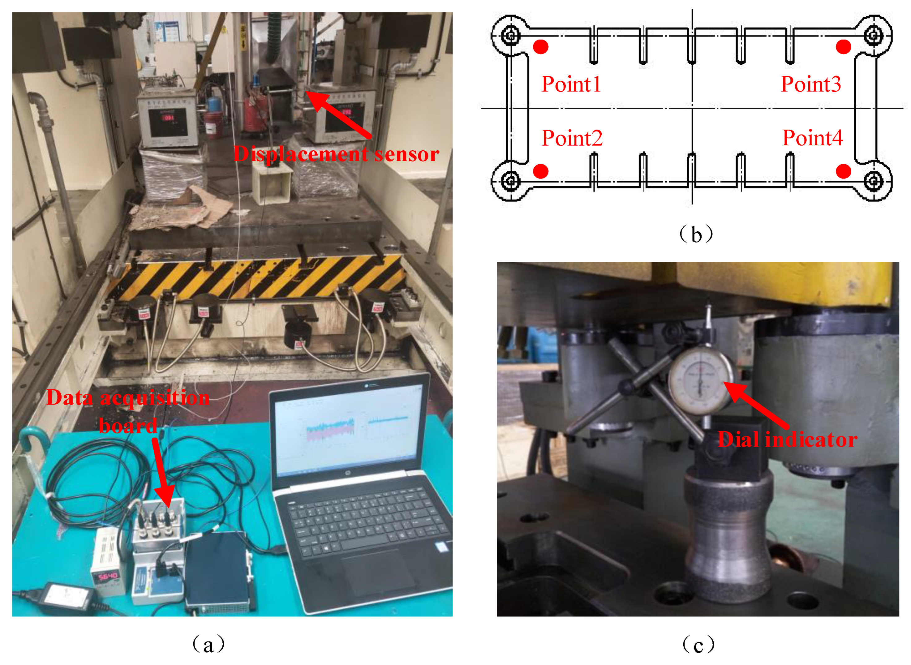
After the equipment was processed and assembled, the elbow bar press was debugged. By testing the position of the bottom dead center of the multi-link mechanism and the parallelism of the slider, the correctness of the proposed error model and accuracy optimization can be verified. A test platform for the accuracy of the bottom dead center of the press and the parallelism of the slider was built, as shown in Figure 9. As shown in Figure 9a, a displacement sensor was placed below the lower dead center of the slider for the lower dead center accuracy test and was clamped by the magnetic meter base and special tooling. The position signal was converted into a voltage signal by the sensor, the data acquisition card collected the conditioned voltage signal, and the data acquisition program edited by LabVIEW converted the voltage signal into displacement for real-time storage and display.

Figure 9.
Measurements of slider displacement and parallelism. (a) Displacement test spot (b) Diagram of inclination measuring points (c) Inclination test spot.
The parallelism of the slider was obtained by measuring the points on the four corners of the bottom surface of the slider. The schematic diagram of the measuring points is shown in Figure 9b. We wiped the sliding block and the area to be measured on the workbench and marked the positions of 4 measuring points on the upper surface of the workbench. We adjusted the slider to near the bottom dead center position, placed the dial gauge at the first position for zero calibration, and then measured the reading of the dial gauge at each measuring point. The test site diagram is shown in Figure 9c.
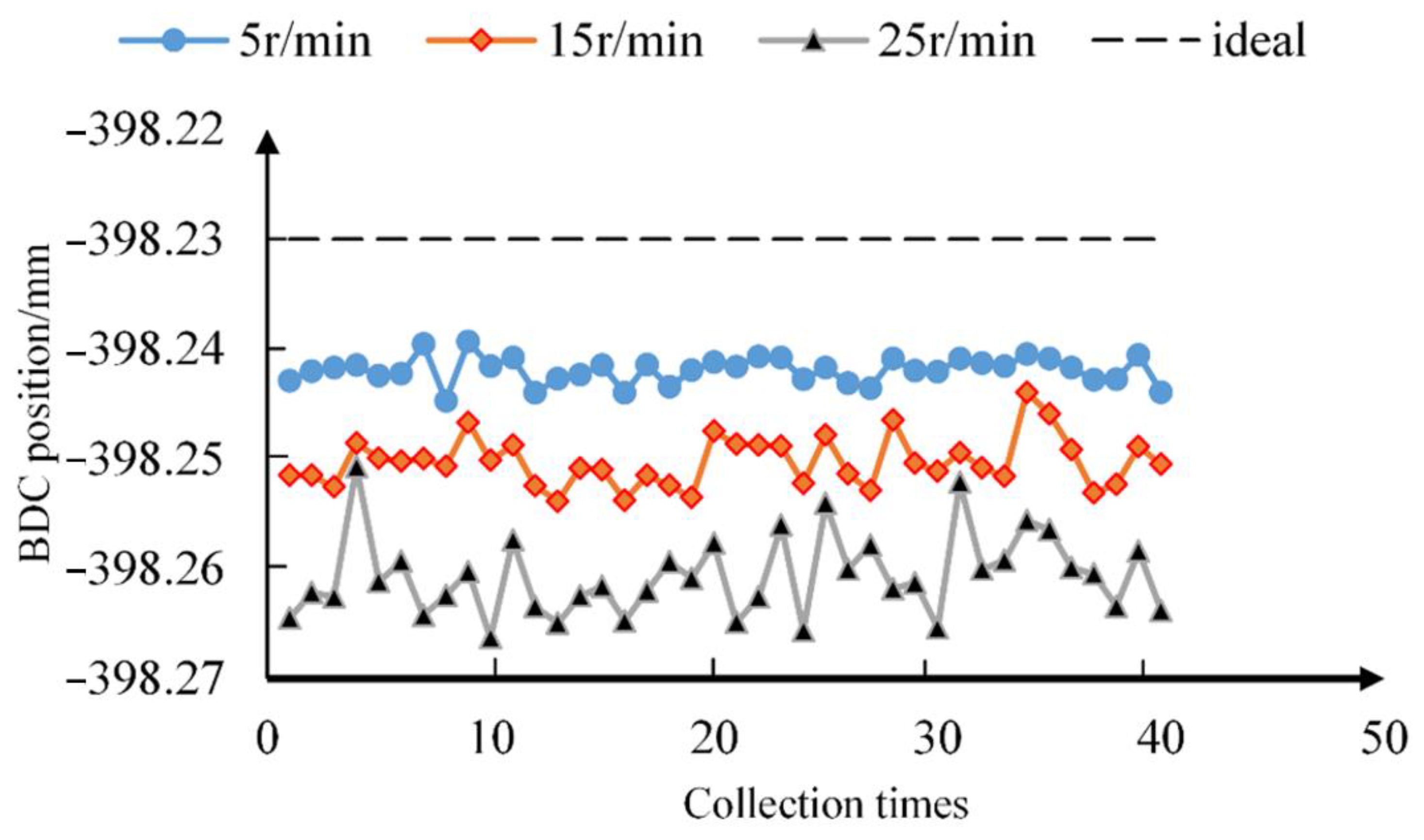
The dynamic accuracy of the BDC of the toggle press at different speeds was measured and statistically analyzed. As can be seen from Figure 10, 40 sets of slider displacement data are available, so we can get the BDC position data. As the rotation speed increases, the BDC position of the slider moves down. The ideal theoretical BDC value obtained by simulation calculation is 398.23 mm. Compared with the ideal BDC position data, the actual measured BDC position error of the elbow bar press does not exceed 0.05 mm, which meets the design requirements of the slider position error.
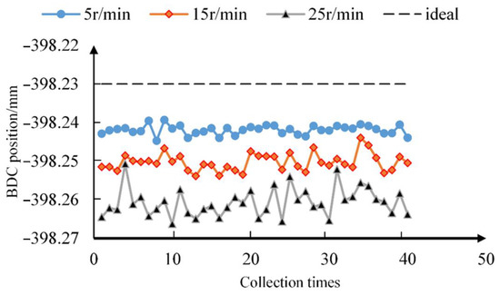
Figure 10.
Positions of the bottom dead point at different speeds.
The parallelism of each measuring point of the slider is shown in Table 6. It can be seen from the measurement results that the parallelism of the slider in the left and right directions is 0.17 mm, while the parallelism in the front and rear directions is 0.05 mm. The length of the slider is 1500 mm, so the inclination angle of the slider is 0.000113 rad, which meets the design requirements of the inclination of the slider. The parallelism of the slider is good, which can well meet the requirements of stamping processing.
Table 6.
Parallelism values of each measuring point.
6. Conclusions
In order to ensure the machining accuracy of the press slider, it is necessary to design the accuracy of the transmission mechanism in the design stage. This paper improves the output accuracy of the press slider from the point of view of the tolerance distribution of the bar system processing and manufacturing in the design stage of the press transmission mechanism.
- (1)
- Based on the loop increment method, the error model of the transmission mechanism of the multi-link press was established, which reflects the transmission relationship between the dimensional error of the linkage and the output error of the slider.
- (2)
- The key error sources that have a great impact on the output position error of the bottom dead center of the slider were identified by a sensitivity analysis, which lays a theoretical foundation for error design and allocation.
- (3)
- The detailed process and method of tolerance optimization design of components were proposed, which takes the position accuracy and tilt angle reliability of the slider as constraints and the processing cost as the goal. The processing cost was reduced, while the output accuracy of the press was guaranteed.
- (4)
- Using this method, the example of the tolerance design of an elbow bar press was carried out. Finally, the feasibility and effectiveness of the proposed method were verified by Monte Carlo simulation analysis and experimental testing.
Author Contributions
Conceptualization, methodology, software, validation, formal analysis, writing—original draft preparation, writing—review and editing, X.D.; supervision, Y.S.; All authors have read and agreed to the published version of the manuscript.
Funding
This research received no external funding.
Institutional Review Board Statement
Not applicable.
Informed Consent Statement
Not applicable.
Data Availability Statement
No data available.
Conflicts of Interest
The authors declare no conflict of interest.
Nomenclature
| li | linkage |
| θi | angle between linkage and horizontal direction |
| S | slider stroke |
| e | offset distance of slider |
| Cx/Cz | coordinate of point C |
| Δli | linkage length error |
| Δθi | linkage angle error |
| ΔCx/ΔCz/Δe | position error |
| ΔS | the position error of slider BDC |
| Δβ | the angle error of slider inclination |
| ξi | sensitivity coefficient |
| λi | significance coefficient |
| Ci | relative manufacturing cost |
| ai | tolerance characteristic index |
| Ki | technological coefficient |
| pi | probability of reliability |
| Ei | mean value |
| σi | mean square deviation |
References
- Halicioglu, R.; Dulger, L.C.; Bozdana, A.T. Mechanisms, classifications, and applications of servo presses: A review with comparisons. Proc. Inst. Mech. Eng. Part B J. Eng. Manuf. 2015, 230, 1177–1194. [Google Scholar] [CrossRef]
- Cominotti, R.; Gentili, E. Near net shape technology: An innovative opportunity for the automotive industry. Robot. Comput.-Integr. Manuf. 2008, 24, 722–727. [Google Scholar] [CrossRef]
- Cheng, K.; Shore, P. Special issue on design of ultraprecision and micro machine tools and their key enabling technologies. Int. J. Mach. Tools Manuf. 2010, 50. [Google Scholar] [CrossRef]
- Qian, H.; Tao, J.; Yu, S. Error analysis and accuracy synthesis of high precision press. J. Shanghai Jiaotong Univ. 2019, 53, 7. (In Chinese) [Google Scholar]
- Ferreira, P.M.; Liu, C.R.; Merchant, E. A Contribution to the Analysis and Compensation of the Geometric Error of a Machining Center. CIRP Ann. 1986, 35, 259–262. [Google Scholar] [CrossRef]
- Srivastava, A.K.; Veldhuis, S.C.; Elbestawit, M.A. Modelling geometric and thermal errors in a five-axis cnc machine tool. Int. J. Mach. Tools Manuf. 1995, 35, 1321–1337. [Google Scholar] [CrossRef]
- Jha, B.K.; Kumar, A. Analysis of geometric errors associated with five-axis machining centre in improving the quality of cam profile. Int. J. Mach. Tools Manuf. 2003, 43, 629–636. [Google Scholar] [CrossRef]
- Yang, B.; Zhang, G.; Ran, Y.; Yu, H. Kinematic modeling and machining precision analysis of multi-axis CNC machine tools based on screw theory. Mech. Mach. Theory 2019, 140, 538–552. [Google Scholar] [CrossRef]
- Yang, J.; Altintas, Y. Generalized kinematics of five-axis serial machines with non-singular tool path generation. Int. J. Mach. Tools Manuf. 2013, 75, 119–132. [Google Scholar] [CrossRef]
- Brockett, R.W. Robotic Manipulators and the Product of Exponentials Formula; Springer: Berlin/Heidelberg, Germany, 1984. [Google Scholar]
- Wu, H.; Zheng, H.; Li, X.; Wang, W.; Xiang, X.; Meng, X. A geometric accuracy analysis and tolerance robust design approach for a vertical machining center based on the reliability theory. Measurement 2020, 161, 107809. [Google Scholar] [CrossRef]
- Qiao, Y.; Chen, Y.; Yang, J.; Chen, B. A five-axis geometric errors calibration model based on the common perpendicular line (CPL) transformation using the product of exponentials (POE) formula. Int. J. Mach. Tools Manuf. 2017, 18–119, 49–60. [Google Scholar] [CrossRef]
- Wu, S.; Dong, Z.; Qi, F.; Fan, Z. Prediction of the Comprehensive Error Field in the Machining Space of the Five-Axis Machine Tool Based on the “S”-Shaped Specimen Family. Machines 2022, 10, 408. [Google Scholar] [CrossRef]
- Chen, G.; Wang, H.; Lin, Z. Generalized kinematic mapping of constrained plane motions and its application to the accuracy analysis of general planar parallel robots. Mech. Mach. Theory 2012, 50, 29–47. [Google Scholar] [CrossRef]
- Tian, W.; Gao, W.; Zhang, D.; Huang, T. A general approach for error modeling of machine tools. Int. J. Mach. Tools Manuf. 2014, 79, 17–23. [Google Scholar] [CrossRef]
- Zhao, Q.; Guo, J.; Hong, J.; Liu, Z. Analysis of angular errors of the planar multi-closed-loop deployable mechanism with link deviations and revolute joint clearances. Aerosp. Sci. Technol. 2019, 87, 25–36. [Google Scholar] [CrossRef]
- Chaker, A.; Mlika, A.; Laribi, M.A.; Romdhane, L.; Zeghloul, S. Accuracy analysis of non-overconstrained spherical parallel manipulators. Eur. J. Mech.-A/Solids 2014, 47, 362–372. [Google Scholar] [CrossRef]
- Tian, W.; Liu, S.; Liu, X. Accuracy design of high precision machine tools using error sensitivity analysis methodology. Proc. Inst. Mech. Eng. Part C J. Mech. Eng. Sci. 2016, 231, 3401–3413. [Google Scholar] [CrossRef]
- Chen, M. Error optimization synthesis of planar linkage mechanism. China Mech. Eng. 2003, 14, 2. (In Chinese) [Google Scholar]
- Jin, S.; Zheng, C.; Yu, K.; Lai, X. Tolerance design optimization on cost–quality trade-off using the Shapley value method. J. Manuf. Syst. 2010, 29, 142–150. [Google Scholar] [CrossRef]
- Singh, P.K.; Jain, P.K.; Jain, S.C. Simultaneous optimal selection of design and manufacturing tolerances with different stack-up conditions using genetic algorithms. Int. J. Prod. Res. 2010, 41, 2411–2429. [Google Scholar] [CrossRef]
- Sivakumar, K.; Balamurugan, C.; Ramabalan, S. Simultaneous optimal selection of design and manufacturing tolerances with alternative manufacturing process selection. Comput.-Aided Des. 2011, 43, 207–218. [Google Scholar] [CrossRef]
- Chen, G.; Sun, Y.; Lu, L.; Chen, W. A new static accuracy design method for ultra-precision machine tool based on global optimisation and error sensitivity analysis. Int. J. Nanomanuf. 2016, 12, 167–180. [Google Scholar] [CrossRef]
- Zhang, Z.; Liu, Z.; Cai, L.; Cheng, Q.; Qi, Y. An accuracy design approach for a multi-axis NC machine tool based on reliability theory. Int. J. Adv. Manuf. Technol. 2016, 91, 1547–1566. [Google Scholar] [CrossRef]
- Jun, C.-S.; Kwon, B.-I.; Kwon, O. Tolerance Sensitivity Analysis and Robust Optimal Design Method of a Surface-Mounted Permanent Magnet Motor by Using a Hybrid Response Surface Method Considering Manufacturing Tolerances. Energies 2018, 11, 1159. [Google Scholar] [CrossRef] [Green Version]
- Bai, Y.; Gao, F.; Guo, W.; Yue, Y. Performance analytical study of the dual screws actuation mechanism. J. Mech. Sci. Technol. 2012, 26, 3277–3289. [Google Scholar] [CrossRef]
- Bai, Y.; Gao, F.; Guo, W. Design of mechanical presses driven by multi-servomotor. J. Mech. Sci. Technol. 2011, 25, 2323–2334. [Google Scholar] [CrossRef]
- Lu, X.J.; Zhu, S.H.; Ke, Z.M.; Qin, J.; Wei, S. Influence of Crank Radius on the Curve Shapes for a Multi-Link High-Speed Precision Press. Appl. Mech. Mater. 2011, 141, 313–318. [Google Scholar] [CrossRef]
- Qian, H.; Tao, J.; Yu, S. Error modeling and tolerance optimal allocation of double elbow bar press. J. Donghua Univ. Nat. Sci. Ed. 2018, 44, 7. (In Chinese) [Google Scholar]
- Hsieh, K.-L. The study of cost-tolerance model by incorporating process capability index into product lifecycle cost. Int. J. Adv. Manuf. Technol. 2005, 28, 638–642. [Google Scholar] [CrossRef]

Publisher’s Note: MDPI stays neutral with regard to jurisdictional claims in published maps and institutional affiliations. |
© 2022 by the authors. Licensee MDPI, Basel, Switzerland. This article is an open access article distributed under the terms and conditions of the Creative Commons Attribution (CC BY) license (https://creativecommons.org/licenses/by/4.0/).