1. Introduction
By reflecting on nature, one might see a variety of intelligent animals, each with some degree of intelligence, where all of them learn by experience to convert their potential capabilities into some skill. This fact inspired the machine learning community to devise and develop machine learning approaches inspired by nature, within the field of bio-inspired artificial intelligence [
1]. Further, it motivated us to use the idea of learning by reinforcement signal in this paper. Reinforcement signals (such as positive rewards and punishments) are some of the primary sources of learning in intelligent creatures. This type of learning is implemented and applied by the reinforcement learning family of algorithms in machine learning.
While learning can be considered a type of intelligence, it can only manifest itself when applied to an agent or when used to control one. An agent could be any actual or simulated machine, robot, or application with sensors and actuators. Considering several categories of robots, Unmanned Aerial Vehicles (UAVs) are among the most critical agents to be controlled because they can fly, which means they can move to locations and positions that are not possible for Unmanned Ground Vehicles (UGV) and Unmanned Surface Vehicles (USV). One of the essential considerations in controlling a UAV is its navigation and control algorithm. There are several kinds of methods used for navigation in UAVs, some of them are dependent on some external guiding system (such as GPS), and a couple of them are based on rule-based controllers, which are different from an alive creature.
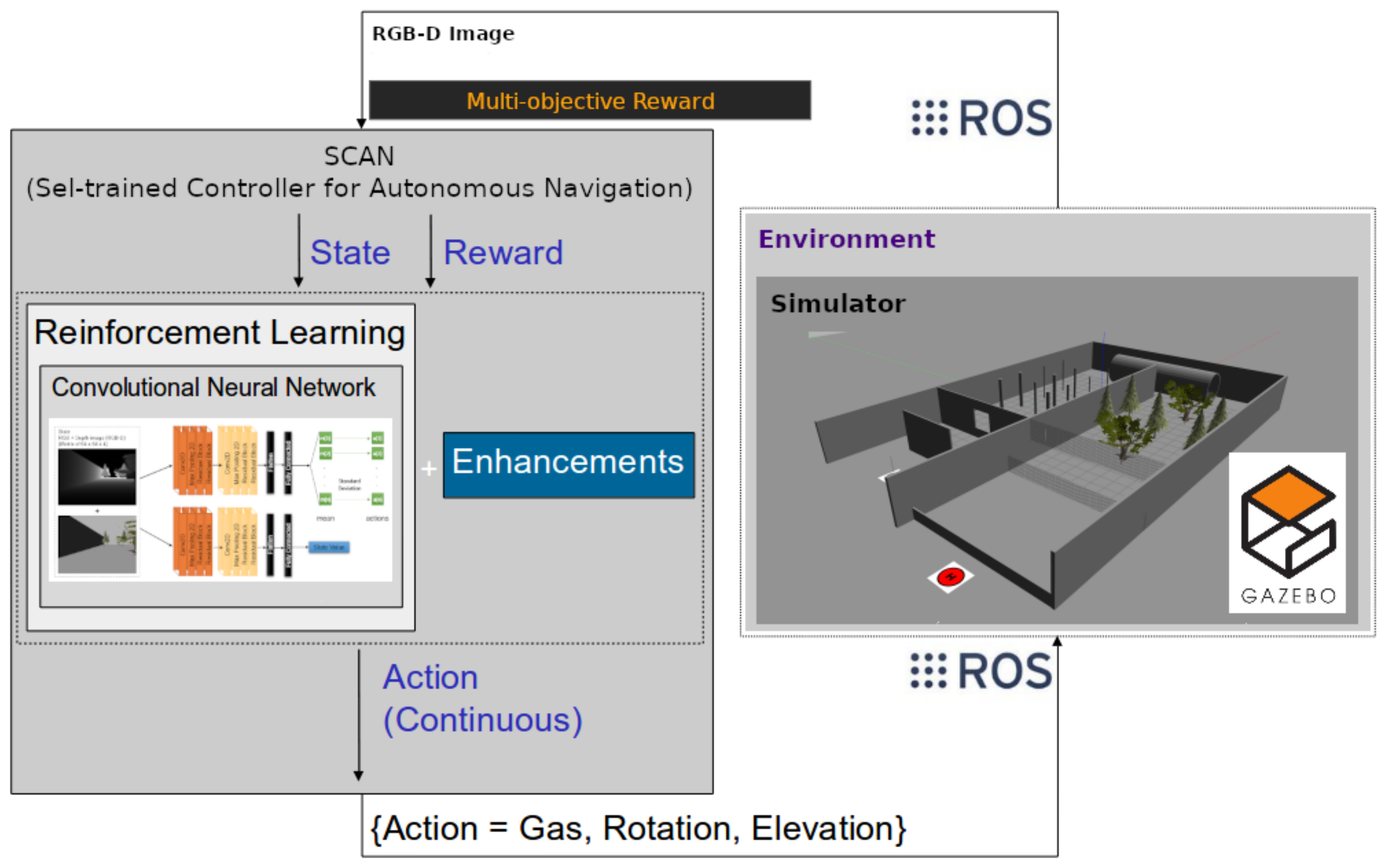
In this paper, we introduce a self-trained controller for autonomous navigation (SCAN) (Algorithm 1) in static and dynamic challenging environments using a deep reinforcement learning-based algorithm trained by Depth and RGB images as input, and multiple rewards. We control the UAV using continuous actions (a sample generated trajectory by our algorithm is shown in
Figure 1) and train our RL algorithm in a multi-objective way in order to be able to reach a defined goal area while learning to avoid static and dynamic obstacles. We train our robot in a simulated environment using Gazebo sim., and for the communication between the algorithm and simulated agent, we use Robot Operating System (ROS).
In the rest of this text, we first discuss the related literature and then explain our main work with a detailed explanation for each part of our proposed algorithm, such as enhancements, neural networks, obstacle detection method, reward calculation, and trajectory visualization (In this research, to visualize the 3D trajectory in a 3D environment, we used 3D-SLAM. However, SLAM is used only for visualization purposes, and it is not used in any way for training, playing, or control of the UAV). In the next step, we present our results and discuss some crucial aspects of our work before the conclusion. Before starting our literature review, we want to emphasize the contributions of our paper here:
First, we proposed a new RL-based self-learning algorithm for controlling a multi-rotor drone in 3-DoF (x, y, and z) in highly challenging environments;
Second, our proposed algorithm simultaneously trains the policy and value networks using several rewards to create a multi-objective agent capable of learning to traverse through an environment to reach a goal location while avoiding the obstacles;
Third, we verified our algorithm using two highly challenging environments, including static and dynamic obstacles (such as moving walls and nets);
Fourth, our algorithm is an end-to-end self-learning controller in which the RGB-D image is the input to the policy network, and three-dimensional continuous action (gas (moving forward), rotation (to left or right), and elevation) are the output of our algorithm;
Fifth, we used an onboard method (that is, defined within our algorithm, not received from external sources such as simulator) to calculate the reward related to obstacle avoidance and prediction of collisions, which makes our method capable of further learning after deployment on a real UAV.
2. Related Work
In this section, we first review works that used a rule-based controller such as PID, SMD, MPC, or LQR for control of the robot (UAV), then focus on works that used deep learning, or deep reinforcement learning, or reinforcement learning for low-level and high-level control of the UAV.
Looking at the literature, there are a couple of approaches that used rule-based methods for autonomous navigation. For example, the authors of [
2] proposed a path planning algorithm using ant colony clustering algorithm. In [
3] is proposed a method for generating a navigation path considering the energy efficiency. In [
4], Singh et al. proposed an approach for obstacle avoidance in challenging environments. An approach for navigation and guidance proposed in Mina et al. [
5] capable of multi-robot control and obstacle avoidance. Another approach for swarm robot control in terms of guidance and navigation is proposed in [
6].
In addition, reinforcement learning and deep RL are used in several works to create intelligent autonomous robots by acting as the low-level and high-level flight controllers in Unmanned Aerial Vehicles (UAVs). In the high-level case, the controller generates the waypoints or trajectories and passes them to the low-level controller, and in the low-level case, the controller receives the waypoints or trajectories and executes them on the quad-copter either by sending speeds to the motors or by generating the proper forces. In terms of the low-level flight controllers, in work by Ng et al. [
7], authors captured the flight data of a helicopter and used it to create a transition model for training low-level flight controllers for helicopters. Linear quadratic regulator (LQR) and differential dynamic programming (DDP) were used in [
8] to develop an RL-based flight controller. Hwangbo et al. [
9] proposed a low-level flight controller capable of generating motor speeds using reinforcement learning and proportional-derivative (PD). Molchanov et al. [
10] proposed an approach focused on developing a low-level RL-based flight controller that automatically learns to reduce the gap between the simulation and actual quadcopters. The authors of [
11] develop a method of combining PD controller and reinforcement learning-based controller for controlling a quadcopter in faulty conditions and use LSTM networks to detect the fault in different conditions.
In terms of high-level control using reinforcement learning, [
12] proposed a method to control the drone using Deep RL for exploration and obstacle avoidance. In [
13] by Zhang et al., guided policy search (GPS) is used after training in a supervised learning approach using data provided by the model predictive controller (MPC) and Vicon system for accurate position and attitude data. Liu et al. [
14] used virtual potential field to develop a multi-step reinforcement learning algorithm. In [
15], deep RL is used for obstacle avoidance in challenging environments. Long et al. [
16] used a deep neural network in an end-to-end approach for efficient distributed multi-agent navigation, and their algorithm is capable of obstacle avoidance during navigation. In [
17], deep RL is used to create a controller capable of path following while interacting with the environment. Zhou et al. [
18] analyzed deep RL in challenging environments for formation path planning and obstacle avoidance. Liu et al. [
19] used RL and probability map to create a search algorithm and improve the detection ability of the algorithm. Finally, deep RL is used for local motion planning in an unknown environment in [
20], and for trajectory tracking and altitude control in [
21].
In contrast to many rule-based and traditional methods that perform weakly in complex and dynamic environments and high dimensional state spaces, deep reinforcement learning algorithms can control the system by learning to generate the best action considering the defined reward and high dimensional sensor data as their state value. Further, RL-based algorithms have the advantage of autonomous learning from their own experiences, making them highly flexible and capable of learning to control, a feature which is not available in rule-based control algorithms or is limited.
In a nutshell, our work differs from rule-based algorithms and methods, mainly because our algorithm learns to control, but in a rule-based control algorithm, everything is designed and calculated beforehand. Further, it is different from a couple of Deep Learning and Deep RL works where it learns from high dimensional state space to control the UAV by generating waypoints in the XYZ axes. Many of the works reviewed in the literature either use only two dimensions for the control or do not use the high-dimensional state space of RGB-D as we used. For example, in [
15] they focused on obstacle avoidance from RGB image, while our algorithm addresses obstacle avoidance and reaching to goal location from RGB-D image. Moreover, while some works such as [
17] focused on following a path, our algorithm generates a path. Further, compared to works such as [
18] where a Deep Q-Network capable of generating discrete action is used, in our work, a policy gradient-based reinforcement learning algorithm capable of generating continuous action is used. Compared to another similar work [
20], while we use RGB-D data as the input to our Deep RL and generate 3D-action, they use 2D lidar data and generates 2D action. Further, our goal is an image, and their goal is a point fed to the algorithm. In addition, our method calculates the distance with obstacles and predicts the collision internally, making it possible for our algorithm to continue training even after deployment on an actual drone.
3. Self-Trained Controller for Autonomous Navigation (SCAN)
We use an infinite-horizon Markov Decision Process (MDP), defined by the tuple
, to formulate our problem of learning to navigate in challenging environments using a multi-objective reward. Let
S be a finite set of states,
A be a finite set of actions,
be the transition probability distribution,
be the reward function,
be the distribution of the initial state
, and
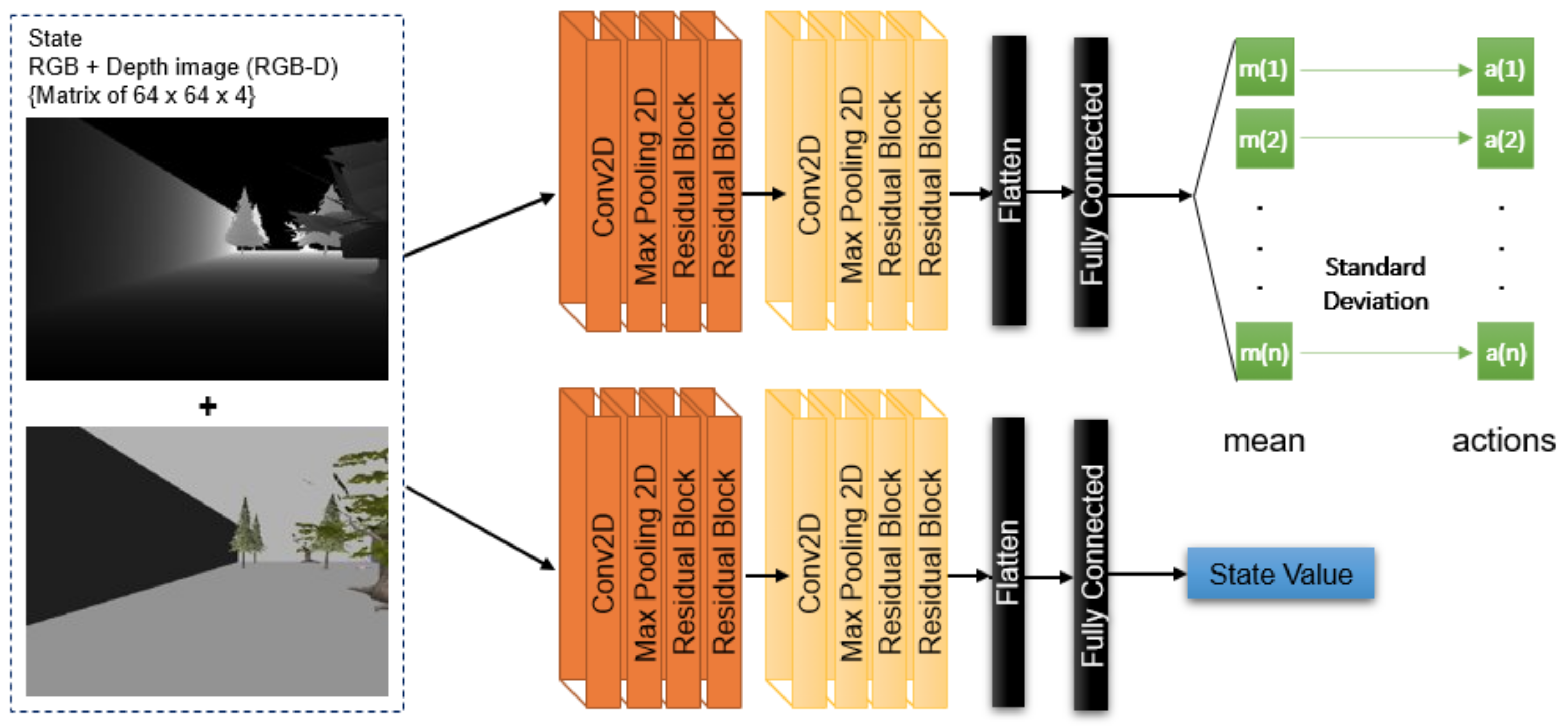
be the discount factor. Our goal is to train a reinforcement learning-based agent to learn to control a UAV drone to navigate through challenging environments. Our state space is 64px by 64px, depth image or RGB image:
Our action space is a three-dimensional continuous space vector, including controlling the height (Elevation), turning left or right (Rotation), and moving forward (Gas).
For solving the problem of learning a high-level flight controller we used proximal policy optimization [
22], a policy gradient-based reinforcement learning algorithm, with some enhancements mentioned at the end of this section for training and optimization of our the algorithm. We use the following conventions:
we define
to be a stochastic policy
, and
to be its expected discounted reward. Then, we define the following expression as the expected return of another policy
in terms of the advantage over
:
Let
be the discounted visitation frequencies:
where
, and the actions are chosen according to
. We can rewrite Equation (
1) with a sum over states instead of time steps:
With attention to the complex dependency of
on
, we used the following approximation instead or the one mentioned in the previous equation:
Considering
to be a differentiable function of parameter vector
, then
matches
to the first order. That is, for any parameter value
,
Further, as mentioned in the following, we use an improvement bound (Kullback–Leibler (KL) divergence,
[
23]) Additionally, we overload our previous notation to use functions of
rather than
, e.g.,
.
is referring to the previous policy.
Next, we use policy
to generate a trajectory
where
T is the length of an episode. We also calculate
.
should be calculated at each state–action pair
by taking the discounted sum of future rewards along the trajectory.
Using Equation (
3), we obtain the following equation:
For each
, we can calculate the first term by:
In the next step, we try to solve the following constrained optimization problem and update policy parameters:
We generate a sequence of states using
and
for n steps, and generate a trajectory
, and re-calculate
.
. The following equation is used to make a general policy:
To solve the optimization problem without a constraint and using a penalty, it is possible to use the following formula:
Considering
, where
, maximizing a surrogate objective would be as follows:
where
CPI is conservative policy iteration [
24]. To maximize Equation (
10) without a constraint the following equation is used to penalize changes to the policy that move
away from 1:
where
is a hyper-parameter equal to 0.2, for example. Further, instead of Equation (
11), or in addition to it, it is possible to use the following Adaptive KL Penalty Coefficient loss:
where in each iteration, we use the following calculation to obtain the new
:
where
and
are coefficients,
S is an entropy bonus, and
is a squared-error loss
Further, we use the policy gradient implementation mentioned in Mnih et al. [
25]:
| Algorithm 1 Self-trained Controller for Autonomous Navigation (SCAN) Algorithm |
| Initialize neural network weights for policy and value networks |
| while True do |
| Generate state |
| Feed state to neural network, generate action , execute in the environment, receive the new RGB-D frame |
| Distance, Collision Occurred = Process the depth frame using the method explained in Section 3: |
| (1) Using RANSAC find the ground plane in the re-projected depth data; |
| (2) Remove all the points belonging to the ground plan; |
| (3) Consider the rest of the points as obstacle points, and calculate distances between the robot and the obstacle points; |
| (4) Return Calculated Distance and Collision Occurred. |
| if (Collision Occurred) then |
| Reset the UAV position using the enhancements explained in Section 3.1 |
| Generate new state |
| end if |
|
| where |
|
|
|
| if TRAINING then |
| Store experience in experience storage |
| if EPISODE finished then |
| Update neural network using the episode experiences considering the following equation: |
|
|
| Use enhancements explained in Section 3.1 to reset UAV position |
| end if |
| end if |
| end while |
Then, we use a truncated version of generalized advantage estimation as shown in the following:
Finally, in order to increase the learning speed and performance of our proposed algorithm, we introduce some enhancements that are similar to enhancements mentioned in [
26] targeting the exploration mechanism of our algorithm.
A neural network with two convolutional layers enhanced by residual layers and one hidden layer of 256 neurons in each layer with ReLu activation function is used to train the model for SCAN,
Figure 2. As we used PPO in this work for the RL algorithm, we have two neural networks. The policy and value networks have a similar shape except for the output layers, where the value network has one output, the state value, and the policy network has n outputs, which are the mean values. Mean values generate the actions after being summed with noise. The flow of information in our algorithm is shown in
Figure 3, and the simulated UAV quad-copter is shown in
Figure 4.
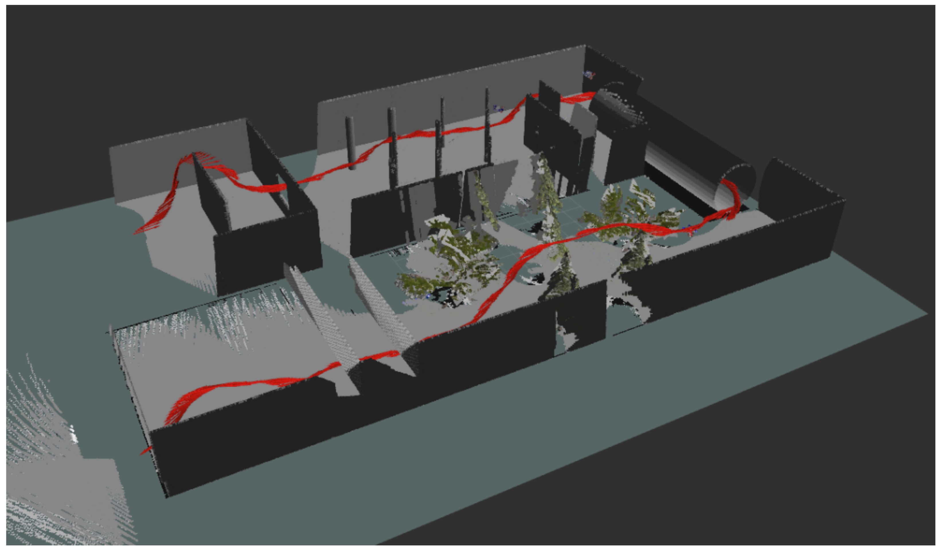
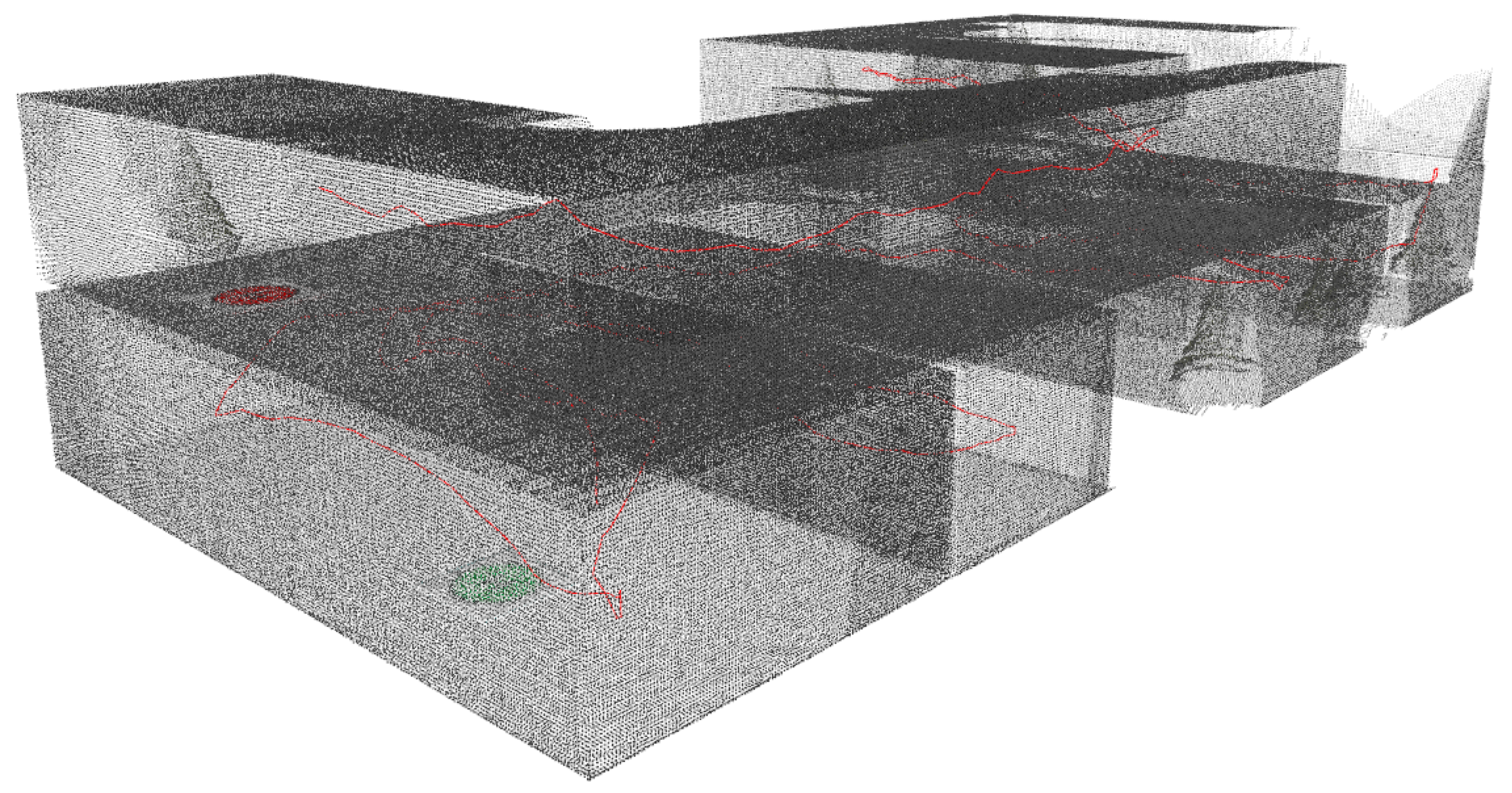
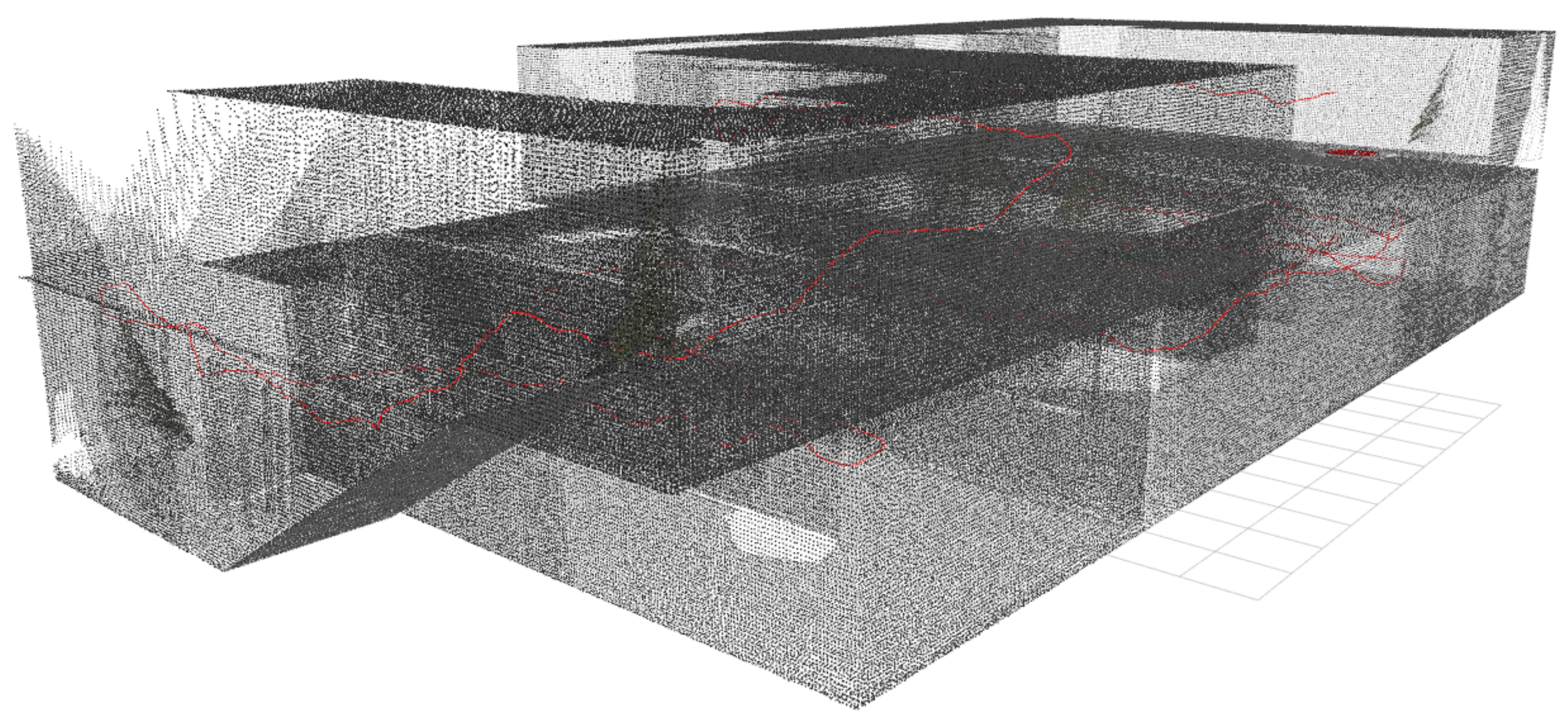
Figure 1.
Trajectory of the UAV controlled by our proposed algorithm (SCAN). SCAN is able to control the UAV in three dimensions (X, Y, and Z). The image is generated by the SLAM approach (only used for visualization purpose) explained in the
Section 4.3.1 of this paper.
Figure 1.
Trajectory of the UAV controlled by our proposed algorithm (SCAN). SCAN is able to control the UAV in three dimensions (X, Y, and Z). The image is generated by the SLAM approach (only used for visualization purpose) explained in the
Section 4.3.1 of this paper.
We use our method published in [
27], where a RANSAC-based algorithm is used to detect the ground plane and distinguish the obstacle points for obstacle detection. Getting so near to these obstacle points will be considered a collision. As a result, instead of using the simulator to report the collision, we calculate it on our algorithm side. In this way, it is possible to use the algorithm to detect the obstacle even after deploying the algorithm onboard a real drone and continue the training in the actual drone.
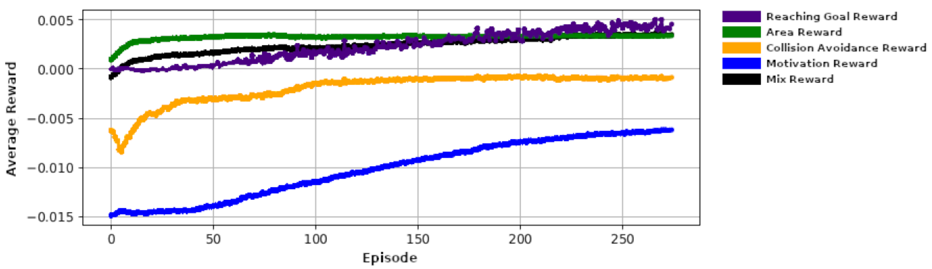
For training our SCAN algorithm, we defined several rewards (that is, a multi-objective reward called ) where each one of them can be considered as an objective for the algorithm. The rewards used in our algorithm are explained in the following:
Collision Avoidance reward: Hitting the obstacles will give a negative reward of −1, that is, .
Area reward (): Moving from one area to the next will return a reward of +1.
Reaching Goal reward (): Reaching the goal location (the red sign at the end of the environment) will return a positive reward of +5
Motivation Reward (): In order to keep the agent motivated to move, we defined a small positive reward relative to the amount of the movement to the agent. Further, in order to increase the effectiveness of this reward, we added a coefficient as shown in the following formula, where depending on the , could have a positive or negative value.
As a result, we define the
using the following equation:
3.1. Enhancements
In this section, we define two modification to the state exploration of the RL algorithm that highly increases the performance of the SCAN in learning to traverse through the environments.
3.1.1. Random Starting Position (RSP)
In order to give the drone the capability of starting from different positions in the middle of the trajectories, we define a new distribution called Random Starting Position (RSP). This new distribution will be used beside the initial starting state distribution (D) of the MDP. We define RSP to be:
Considering the fact that we are using a policy gradient algorithm that uses the trajectories of the same episode for training the policy and value network, the idea of RSP will help the agent to gather the sample trajectories from different positions on the map, which in turn will help the agent to learn faster, in a balanced way, and at the same time avoids catastrophic forgetting in neural network training, where emphasizing on a specific subset of samples will cause the network to diverge from what is already learned.
This idea is borrowed from how infants learn. Consider a parent who tries to help their infant learn to play with a toy. Every time the toy falls from the hand of the infant, the parents give the toy to the infant’s hand again and help their infant try and play with the toy.
3.1.2. Controlled Starting State (CSS)
In addition to the idea of RSP, where we reset the UAV to random positions in the environment, we define Controlled Starting State (CSS), which we use to measure the agent’s performance when it starts from each subset of the environment. In other words, we divide the starting positions in the environment into n subsets and initially give the value of 0 to each subset. In the next step, every time we reset the UAV to any of these subsets, we measure the value gathered from that subset until the terminal state. In other words, we collect the accumulated reward starting from that subset. Further, the next time the agent starts from this position, we add the new accumulated reward with the old CSS value related to that subset and divide it by 2. In other words, we always have the mean value of the latest two accumulated rewards gathered from that starting CSS.
Finally, we use CSS with RSP to alternatively start the UAV from a random position and the position with a minimum CSS value. Doing this will help the agent focus on learning to navigate from the positions in the environment that statistically was unable to gather a good amount of reward from them.
In the following, we define
to contain the value of the subset n of all the subsets defined in RSP:
4. Simulation Environment
Gazebo simulator [
28] is used in this work for training and evaluation of our models. We use the package provided for AscTec Pelican. The benefit of using Gazebo sim. with the provided package is that we can easily connect it to our algorithm using ROS (Robot Operating System), which gives us the advantage of mobility; that is, we can seamlessly move our algorithm to other platforms. We send the actions through our wrapper environment to the Gazebo simulator through the topics provided by RotorS package [
29] and their topics. Further, we receive the RGB-D data from the provided topics, as well.
Furthermore, we gather the RGB-D data and actions results, plus the accumulated reward of the agent throughout the training process, to prove our hypothesis in the result section.
4.1. Static and Dynamic Environments
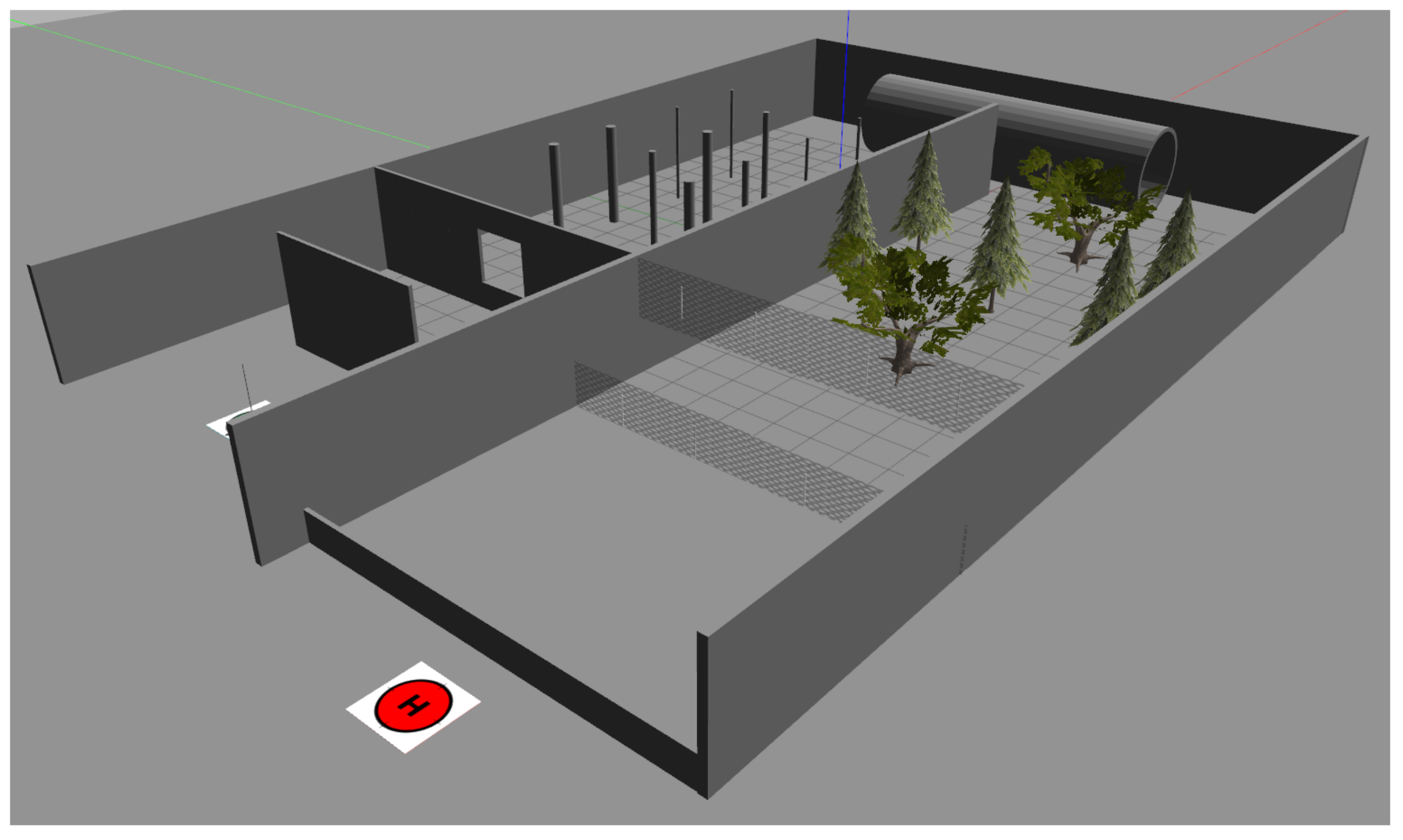
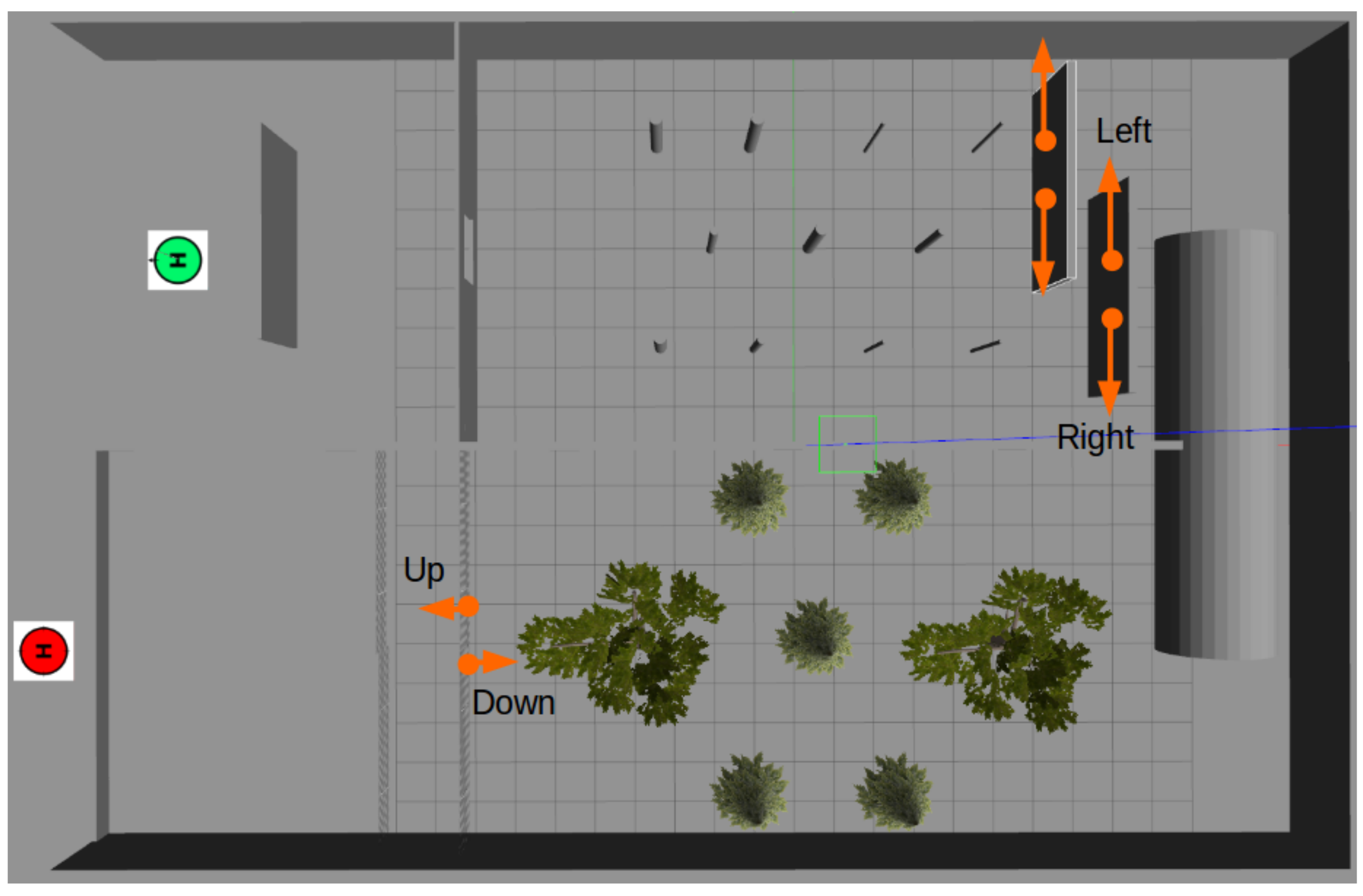
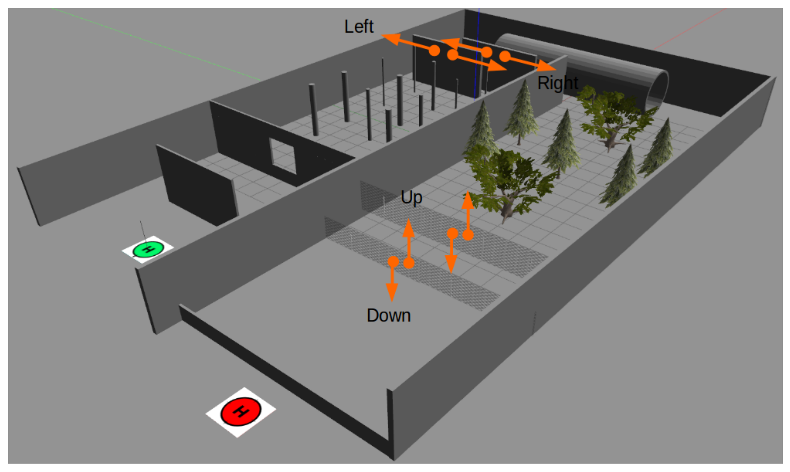
In this work, as it can be seen in
Figure 5 and
Figure 6, we defined a static environment, and as it can be seen in
Figure 7 and
Figure 8, we added two moving parts to the previous environments (two moving walls, and moving nets) to create a dynamic environment. Regarding the dynamic obstacles, that is, the walls and the nets, they move in one direction until they reach the other walls in case of walls, and the ground or max height (that is 3.0 m height) in case of nets. Further, we arranged them to move slightly slower than the moving speed of the UAV.
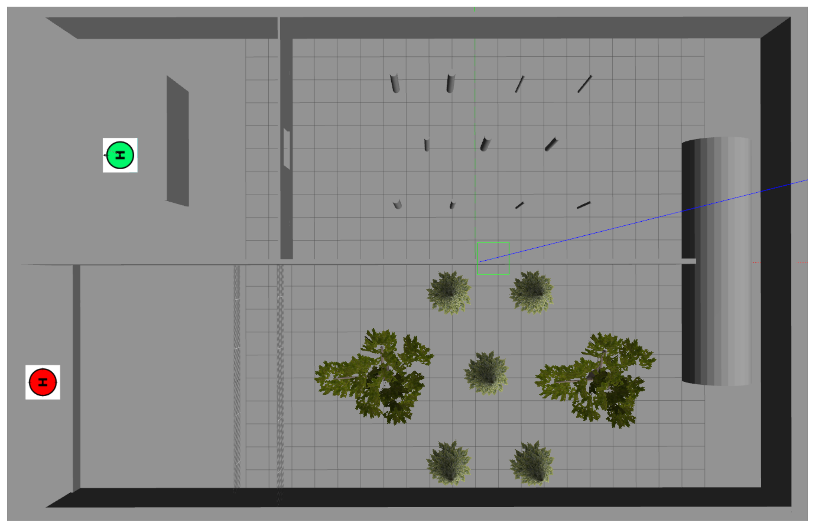
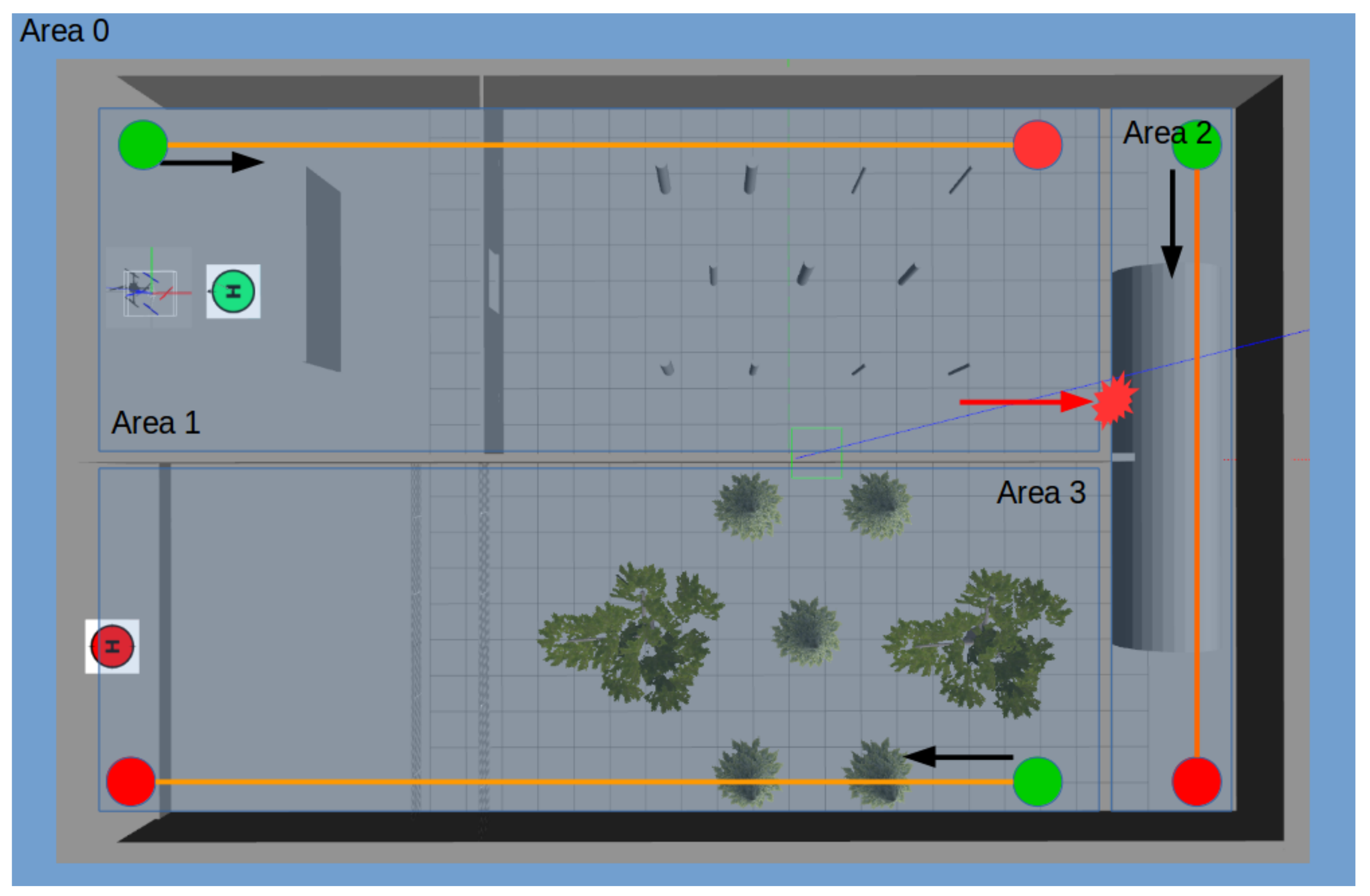
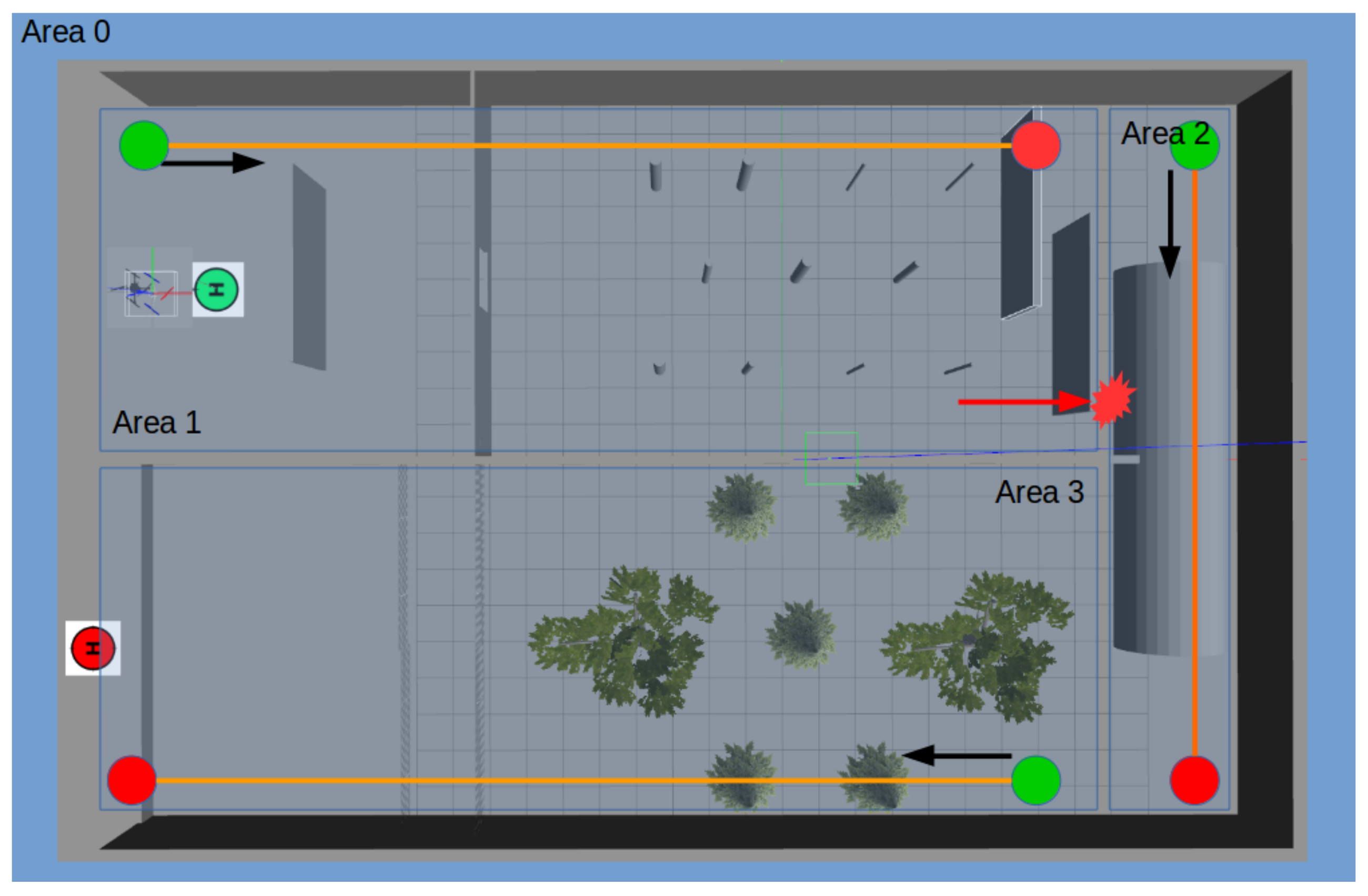
We used these environments to train our agent. Further, as it can be seen in
Figure 9 and
Figure 10, we divided the environment into three virtual areas used for tracing the agent as well as calculating our several rewards for training our agent.
4.2. A New Unknown Environment
After training our agent in the static and dynamic environment mentioned in the previous section, we test it without any further training in a new unknown environment. This environment consists of many rooms and has two floors, and the only way that connect these two floors is a staircase.
4.3. Navigation Visualization
Considering that our algorithm is a high-level controller that generates the proper sequence of the waypoints to control the drone in an environment with obstacles, the main point would be the trajectory of the waypoints. As a result, we implement some methods to visualize the sequence (trajectory) of waypoints generated by our algorithm in the top-view map of the environments and the XZ, XY, and YZ planes.
4.3.1. SLAM for Visualizing the Trajectory in 3D Map
In order to clearly illustrate the trajectory of the UAV controlled by our proposed algorithm, considering the fact that our algorithm is controlling the quad-copter in 3-dimension, the best solution from our point of view was to use SLAM. We used SLAM since it can localize the agent in an environment and at the same time does the mapping, and as a result, we can see the trajectory of the agent movement in the environment. As one can see, the images generated by the SLAM we used in this paper are focused on localization and not on mapping. In other words, the mapping result seen in our SLAM images in this paper are the result of moving through the shown trajectory from the starting point of that trajectory to the ending point of the trajectory; that is, we did not focus on the mapping part to generate a perfect map. Finally, here we again emphasize that the SLAM only is used for visualization purposes, and the result of the SLAM algorithm is not used in any way in the training, playing, and control of our algorithm and the agent shown in this paper. We used a SLAM package called RTAB-Map [
30] and set it to use the RGB-D image and odometry data coming from the simulated agent in the Gazebo sim. to generate the mapping and localization information.
5. Experimental Result
5.1. Learning Diagrams
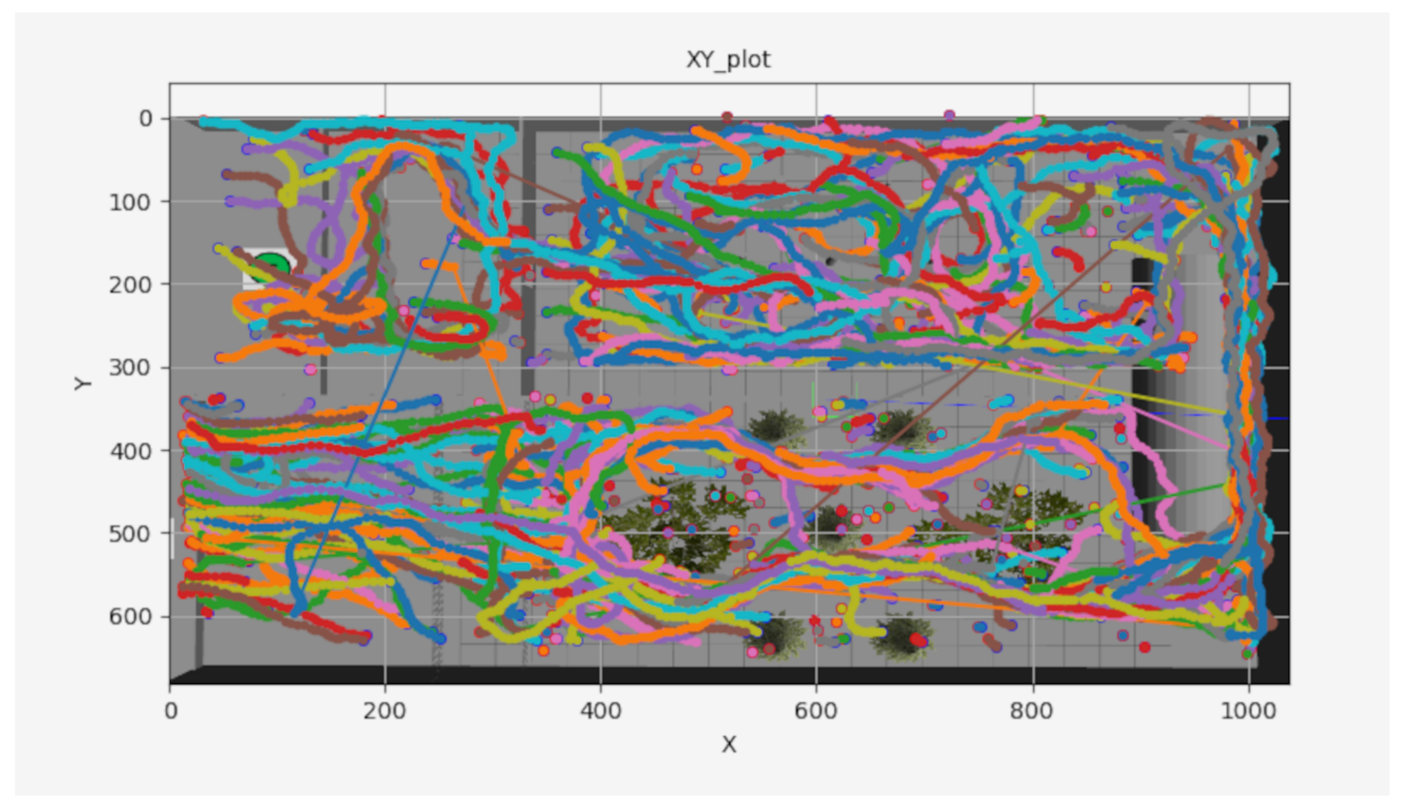
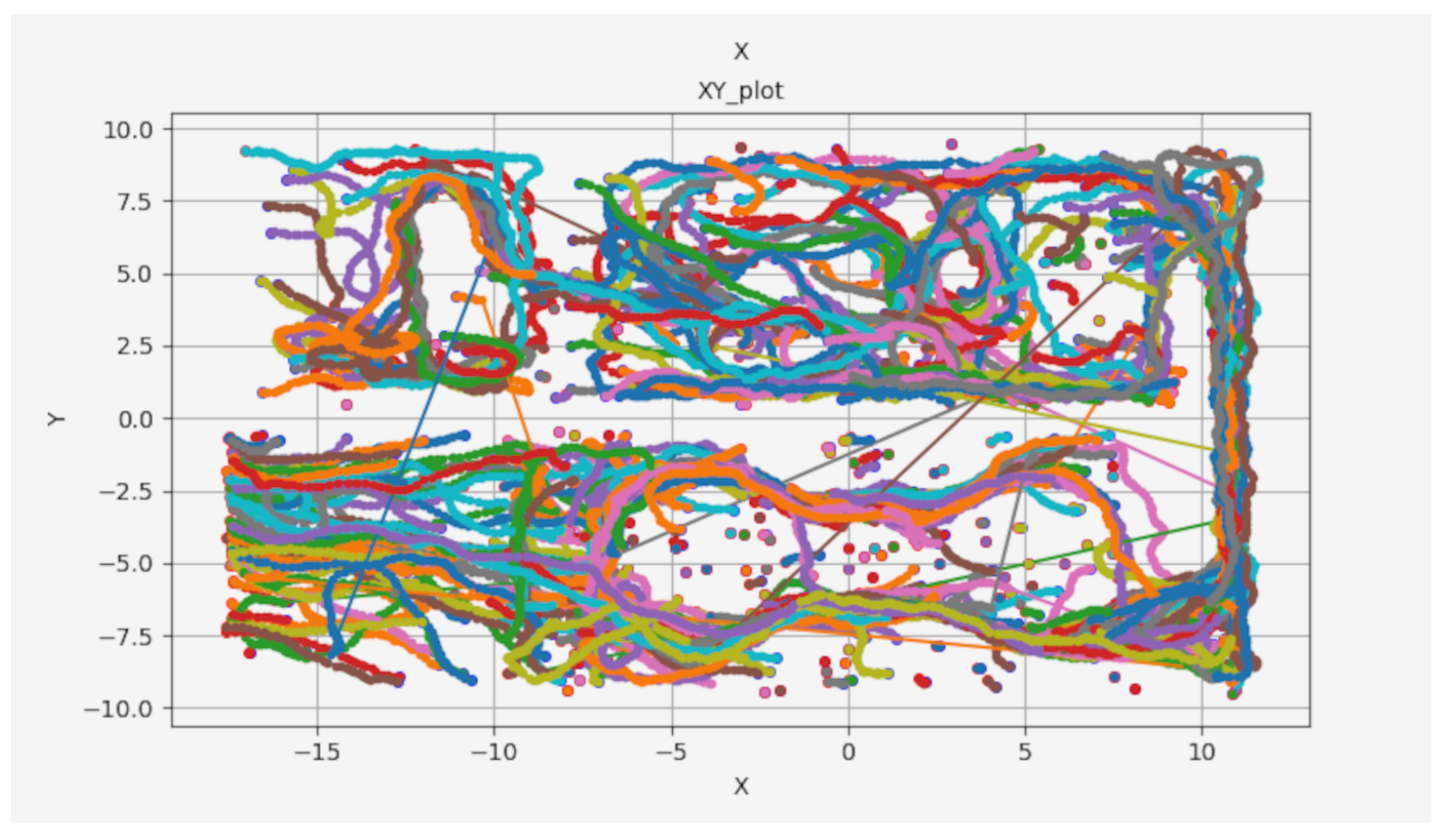
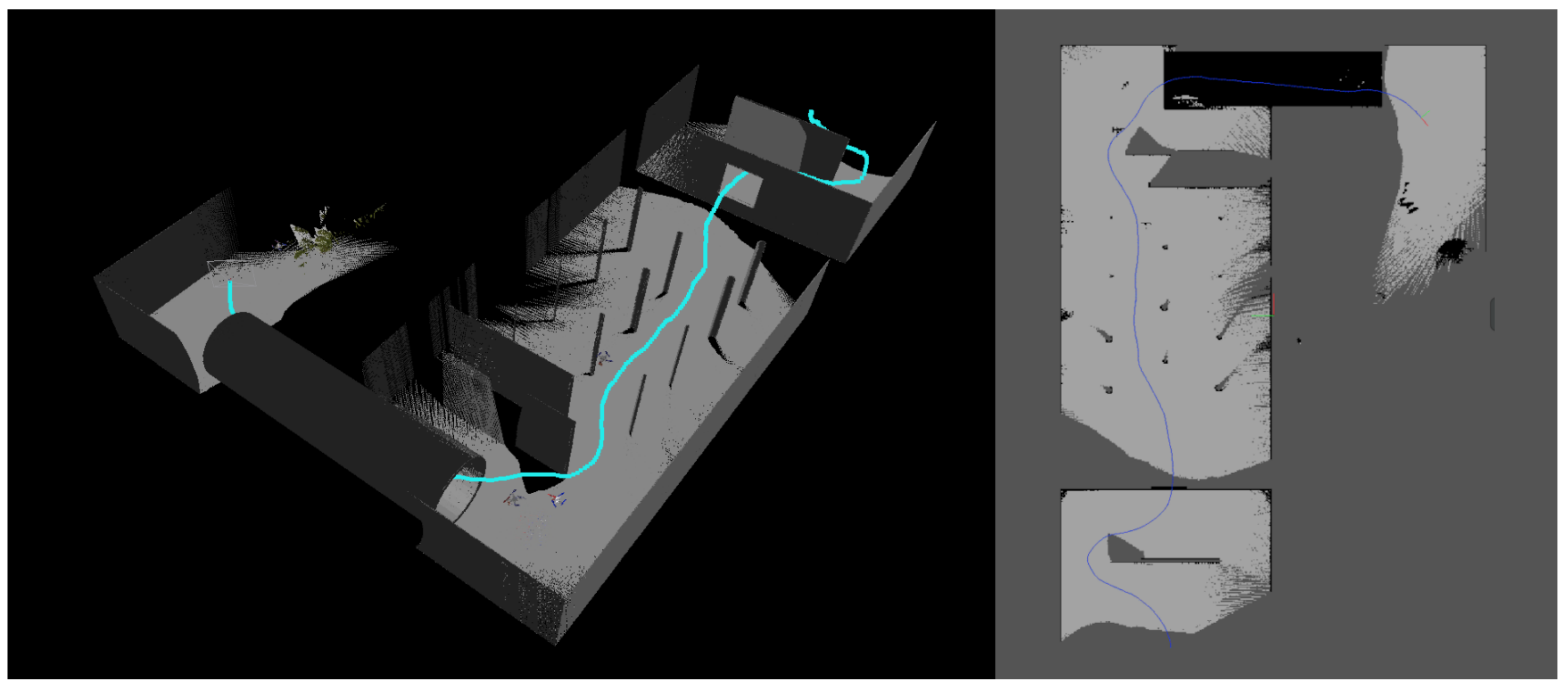
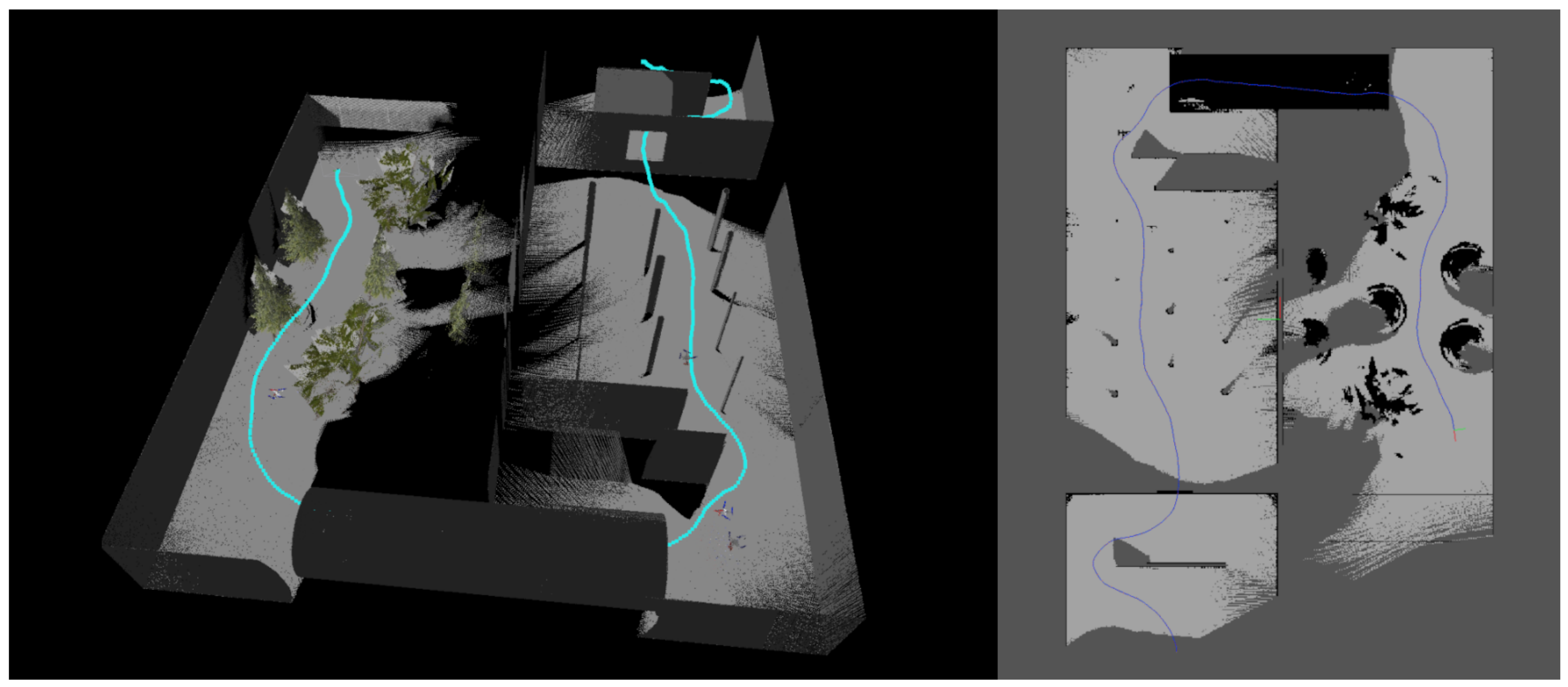
By looking at our navigation results in
Figure 11,
Figure 12 and
Figure 13 (un-trained algorithm) and comparing it with
Figure 14,
Figure 15 and
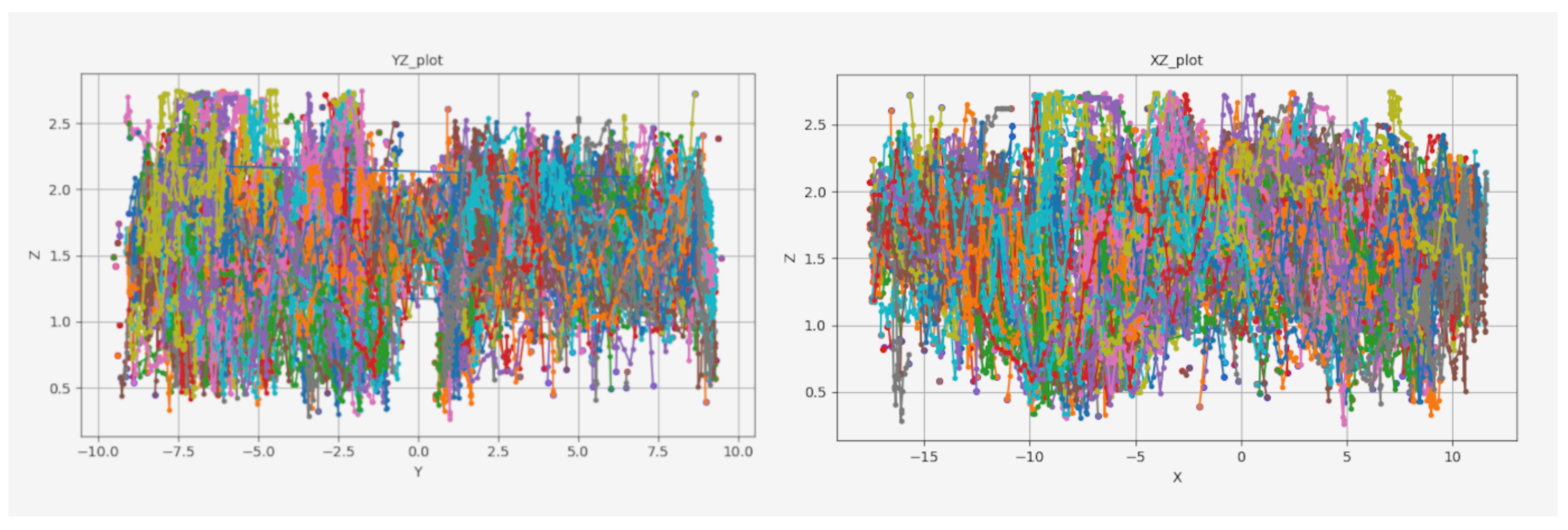
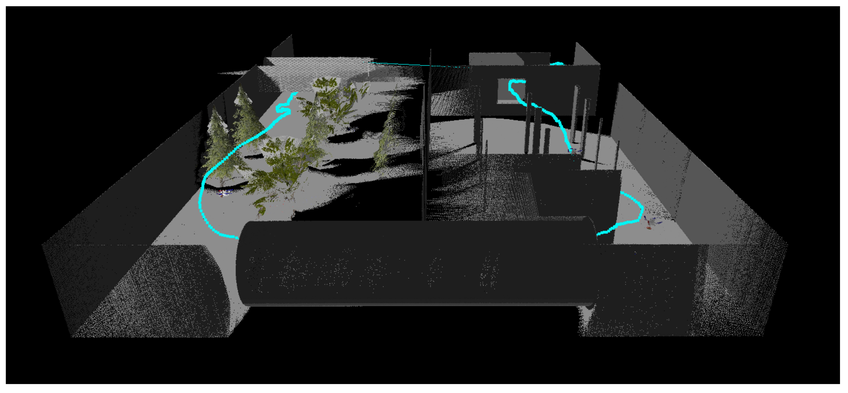
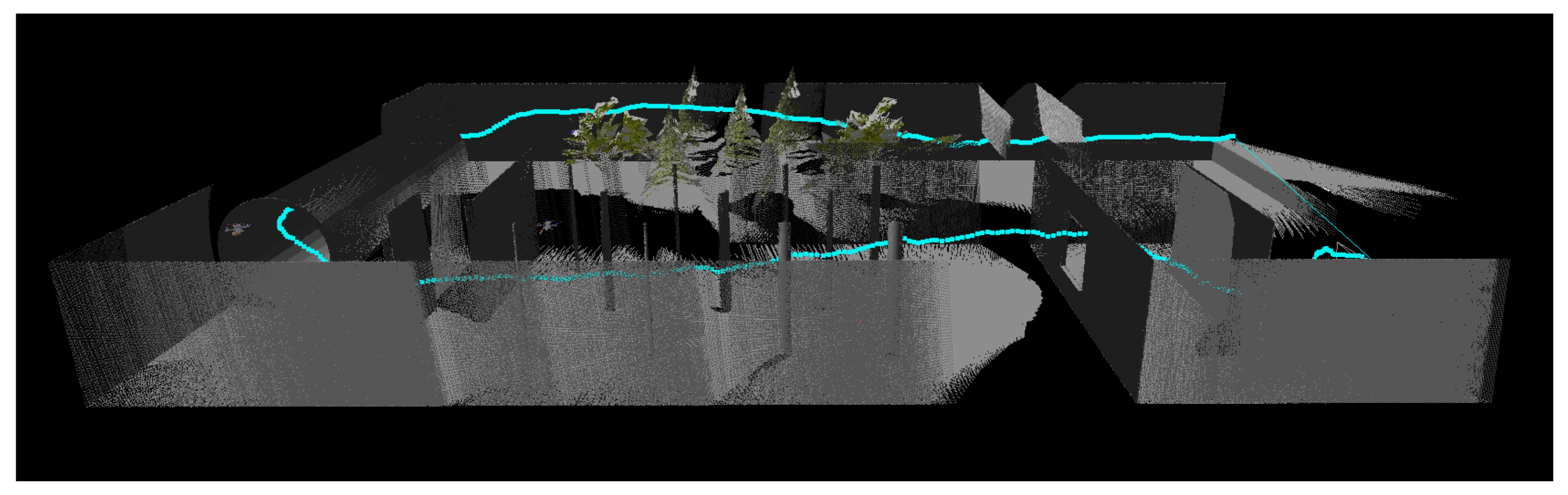
Figure 16 (trained algorithm), it is possible to see that our algorithm learns the shortest path for reaching to the goal position while avoiding the obstacles. The figure also shows the capability of our algorithm to control the UAV in the Z dimension. For example, the UAV is controlled to be at the height of about 1.5 m in the pipe area to pass through it. However, our algorithm increases and decreases the height of the UAV position several times in the area with several trees. Further, to pass the nets (while they are moving up and down), the UAV should be capable of optimal control over the Z dimension. Finally, the data in
Table 1 shows the Success Rate of our trained algorithm, where Success Rate is equal to reaching to the goal location, starting from the beginning of the environment.
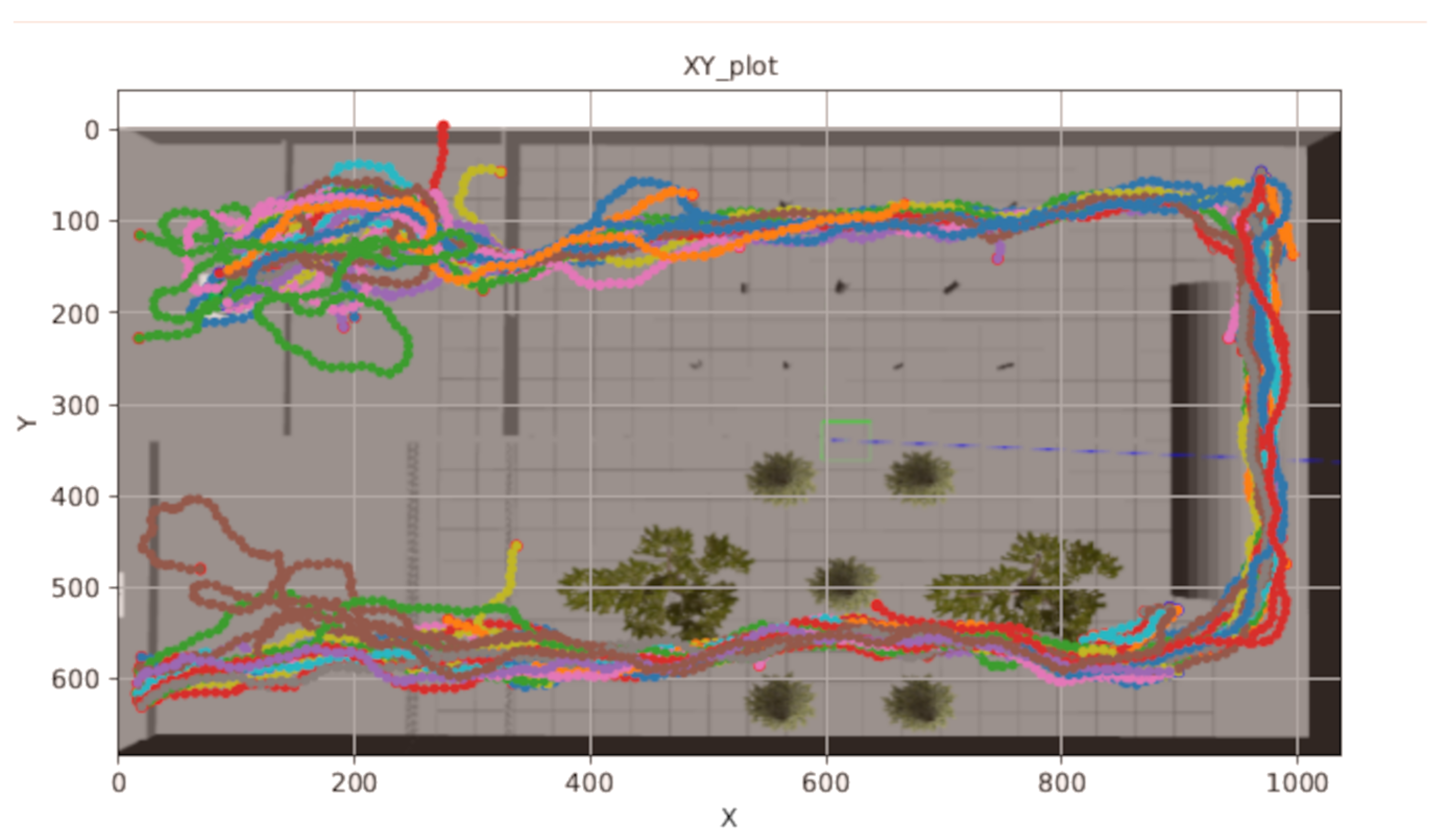
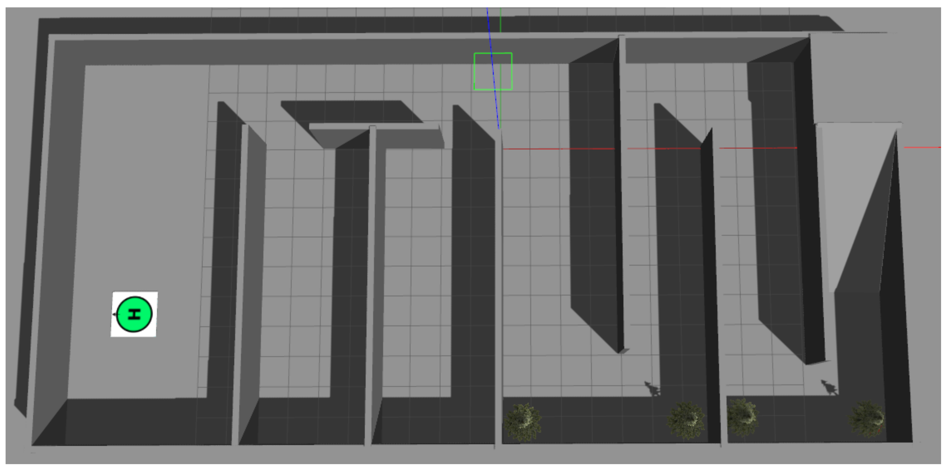
Besides that, as our result in
Figure 17 and
Figure 18 show, our algorithm can learn to maximize the rewards (several rewards that are defined) and also avoid the obstacles. Further, it can learn to reach the final position (the goal position), where the goal position is shown using a JPG image (red H) at the end of the environment.
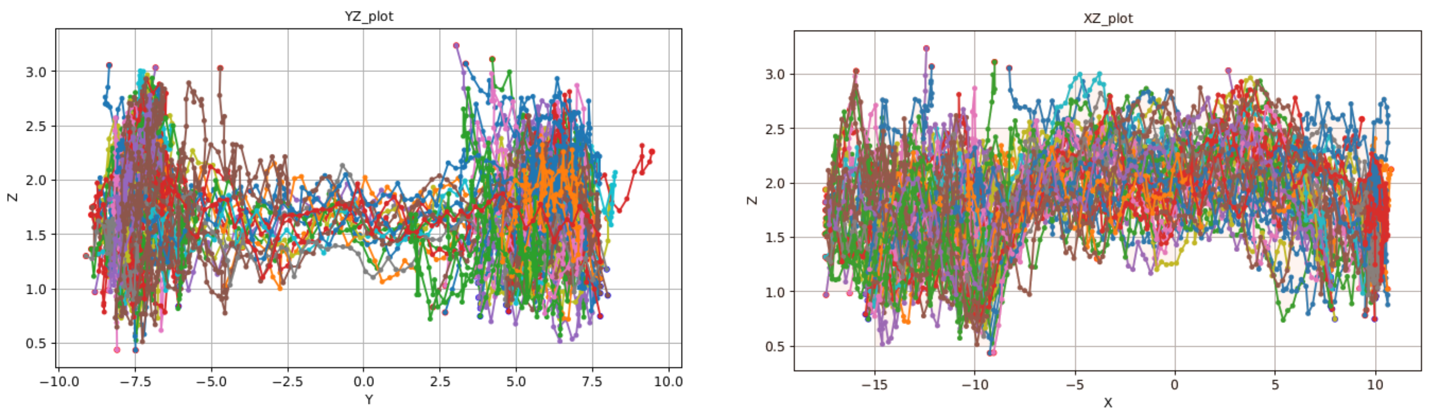
5.2. Trajectory of the UAV Controlled by SCAN
Figure 19 shows the trajectory of the UAV at the beginning of Area 1.
Figure 20,
Figure 21 and
Figure 22 clearly show that the SCAN algorithm can learn to control the trajectory of the UAV to pass through Areas 1, 2, and 3 and maximize the defined rewards while avoiding obstacles. Further,
Figure 23 and
Figure 24 illustrate that the agent is learned to reach the final goal at the end of the challenging environment.
Figure 25 shows the capability of the algorithm in controlling the UAV on the Z-axis, and
Figure 26 shows that the algorithm is able to control the UAV inside the narrow and curved area of a pipe.
6. Discussion
The algorithm we describe in this work is a high-level controller algorithm. That is, it calculates the desired waypoints and sends them to the low-level controller of the UAV. As a result, here, we focus on the issues related to the high-level controller and consider that if the drone can move from point (a) to point (b) in the simulator, having the same command in the actual UAV, it will behave in the same way.
As mentioned earlier, our algorithm as a high-level controller uses the RGB and depth sensors. Further, we use these data to generate the collision signal and calculate the UAV’s distance from the opposite obstacle. While using this method slightly increases the calculation time in each simulation frame, making the online training possible in an actual UAV. If we use the simulator’s physics engine to detect the obstacles and collisions, we would be unable to detect the obstacles on a real drone and use them as new signals for onboard training after deploying the model trained in the simulator.
In this paper, considering the fact that we focused on the capability of the algorithm in terms of being multi-objective and learning to avoid obstacles while being able to finish the environments and reach the goal area, we did not discuss the computational time of our algorithm. However, our algorithm is a model-less Deep RL algorithm which is among the fastest and lightest, considering that from RGB-D image to continuous action commands is just a forward pass through the DNN. Further, it does not use localization methods such as SLAM or methods based on the point cloud, which is proven to be computational-heavy. Finally, our method’s computational load is also related to how many frames per second we need to generate new actions or way-points, which depends on the UAV application. In this research, we used Python and Tensorflow for creating and running our algorithm and generating the results. Further, we used a computer with an i9 CPU and Nvidia 1080ti GPU. This setup takes about 40 ms to generate a new waypoint from the RGB-D image, which means approximately about 25 frames per second. Nonetheless, in the deployment time, the Deep Neural Network weights should be extracted and loaded in a C/C++ code, where the computation is much faster, which compensates for the slower computational power of an onboard system (such as Nvidia TX2 or Nvidia Xavier NX for regular size drones) in an UAV.
Compared to many famous algorithms for planning or obstacle avoidance, where the RGB-D image should be passed through several steps to be converted to useful data such as trees and graphs, our algorithm is an end-to-end algorithm that receives the raw RGB-D image and directly generates the optimal actions or next waypoint. Further, as mentioned earlier, it learns to generate the optimal action by itself; in other words, our algorithm is an autonomous learner agent.
Finally, regarding the dynamic obstacles, they are moving at a constant speed. For every three moves of the UAV, dynamic obstacles move one step. Every time the UAV hits an obstacle or reaches the goal position, obstacles will be re-positioned in a random position along the direction of movement.
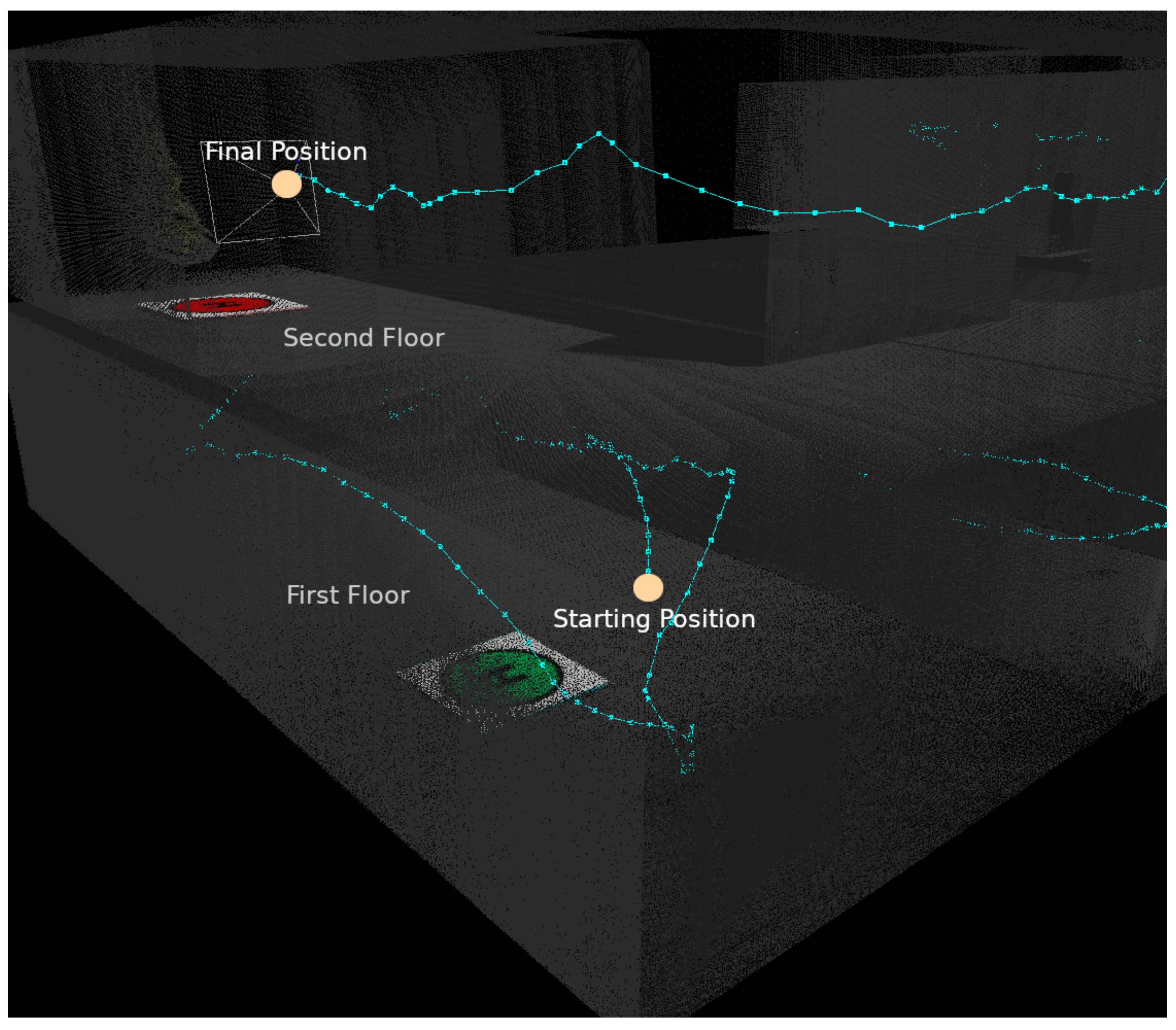
6.1. UAV Trajectory in the Unknown Environment
The second unknown environment consists of many rooms and trees, and also it comprises two floors, where the only way to move to the second environment is through the staircase at the end of the first floor (
Figure 27 and
Figure 28). Considering the trajectory illustrated in
Figure 29,
Figure 30,
Figure 31,
Figure 32 and
Figure 33, related to the unknown environment, the UAV visits one of the rooms on the first floor, then returns to the starting location, and then continues moving through the corridors to the staircase, climbs the staircase, and moves through the corridors, passes through the trees, passes a similar obstacle to the nets, and flies to the target location. To explain the behavior of the UAV in the unknown environment, we believe the model trained in the static and dynamic challenging environment learned a couple of things. It learned to pass through the window and pipe, and perhaps this best explains why the UAV prefers to move through the corridors where they have a similar depth image. Further, it learned to ascend and descend when it wanted to pass the static and dynamic nets, which explains why it is easy for it to climb the staircase. Perhaps one question could be why the UAV chooses to go to the first room on the first floor instead of choosing the corridor, which we believe is due to the Gaussian noises we used to generate the final actions, where it gives a kind of random sense to the controller-generated actions.
6.2. Simulation to Real World Gap
The main issue that can presenr some difficulties for implementing this algorithm (model trained in the simulator) on an actual UAV (quad-copter) would be related to the RGB-D camera noises.
In order to ameliorate this issue, it is possible to: (1) Create an artificial noise in the simulated camera in Gazebo to simulate it as much as possible similar to an actual RGB-D sensor; and (2) Train a Variational Auto-encoder (VAE) network that converts the simulated data to real data before being used for the training of the SCAN algorithm.
7. Conclusions
In this paper, we introduced a self-trained controller for autonomous navigation (SCAN) in a static and dynamic (with moving walls and nets) challenging environment (including trees, nets, windows, and pipe) using deep reinforcement learning trained by Depth and RGB images. We trained our algorithm in the Gazebo simulator in dynamic and static environments, and by illustrating our results, we proved that our algorithm is capable of learning an optimal policy for high-level control of a UAV quadcopter. In this work, we trained our UAV using several rewards, including Obstacle Avoidance reward, Motivation reward, Reaching Goal reward, and Area reward, in a multi-objective fashion with two primary purposes: (1) Avoiding the obstacles (static and dynamic); (2) Learning to reach the desired goal position, that is, where the red sign is shown in the environment. Further, we used an onboard method to calculate the distance of obstacles and predict the collision without using the simulator physics engine.
In this work, we designed and trained our algorithm for controlling the 3 DoF to have a practical algorithm for autonomous navigation of UAVs. Further, we defined our algorithm to use ROS for the communication, which gives the algorithm the advantage of mobility; that is, it can be moved to an actual drone with minimum changes and effort.
Our research result concludes that Deep RL is a capable algorithm in terms of learning to control a UAV and navigate through challenging environments to reach a goal that is shown as a photo and not a single point. Further, it is possible to train the Deep RL algorithm to avoid the obstacles simultaneously in a multi-objective approach. While other algorithms that are not based on machine learning methods are also able to achieve the same goals, many of them are based on localization methods, such as SLAM or point-cloud, which are proven to be computationally heavier than deep RL.
In future work, it is possible to develop the algorithm further to control multiple agents at the same time, while the agents maintain a reasonable formation while following the leader.


