1. Introduction
Ultralight aviation is defined by the FAI (Fédération Aéronautique Internationale) as a sport or recreational vehicle used for manned operations in the air. The specifications of ultralight aircraft are defined in Italy by national laws [
1,
2] in terms of technical standards.
Ultralight aerial vehicles are normally powered by a piston engine connected to a fixed-pitch propeller, but Wankel rotary engines can also be considered. Rotary engines are characterized by compactness, limited vibration, high power–weight ratio, and flat torque curve. On the other hand, Wankel engines experience sealing problems, low power output at low speeds, and, above all, lower thermodynamic efficiency because of the unfavorable shape of the combustion chamber [
3]. In recent years, several studies attempting to improve the combustion processes in this kind of engine have been proposed in the literature. These studies employ simulation and optimization tools previously developed for piston engines and then adapted to rotary engines [
4,
5] to try and improve the thermos-fluid dynamics processes in these engines.
Conventional power systems, with either piston or rotary engines, are advantaged by the high energy density of liquid hydrocarbon fuels but penalized by the low efficiency of the propeller–engine system and by the high environmental impact in terms of greenhouse and pollutant emissions. Energy preservation issues and the need to reduce the environmental impact of aviation have boosted the research on new and more efficient powerplant configurations [
6]. All-electric aircraft [
7] use a battery as energy storage and electric machines to move the propeller. Compared with thermal engines, electric motors have higher efficiency, deliver maximum torque at zero speed, and reduce the acoustic impact. Electricity as an energy source is cheaper than fossil fuel and generates no local emissions. Moreover, the fixed weight of the battery during the flight stabilizes the center of gravity of the aircraft. On the other hand, electric propulsion requires a large takeoff mass and bears a huge encumbrance because of the limited energy density of today’s batteries. For this reason, the application of electric propulsion is limited to small aircraft and short-distance travels.
A hybrid electric power system (HEPS) uses two or more power sources to produce propulsive power so that it can exploit the advantages of conventional and all-electric power systems and reduce their drawbacks. Hybridization improves fuel economy, reduces emissions, and generates very high power at takeoff and climb. Compared with an all-electric configuration, it increases range and endurance, making it also an option for commercial aircraft. These advantages can be counterbalanced by the complexity, bulkiness, and additional weight of this propulsion system. Nonetheless, the weight of an HEPS cannot be obtained by simply adding the weight of the extra component to the original weight of an aircraft [
8]. In fact, a hybrid power system does not require the starter motor and the generator used in conventional configurations, and the large battery available in the hybrid powertrain removes the need for small conventional batteries. Moreover, the mechanical connections can also be reduced. Hybrid electric power systems also have the great advantage of increasing safety in single-engine configurations because the electric drive can sustain the flight, for a short time, also thanks to the possibility to “boost” the electric machine to work at its peak power.
HEPS has two levels of control: supervisory and component-based. The supervisory controller selects, at any time in the mission, the splitting of the power between the two energy sources and defines the setpoints for the lower-level component controller, i.e., the electronic control unit of the engine, the driver of the electric machines, and the battery management system [
9]. The performances of an HEPS are strongly affected by the energy management fulfilled by the supervisory controller. The energy management strategies (EMSs) used in the aircraft field are essentially derived from the huge automotive research on this topic. The main goal of an EMS is the optimization of an appropriate integral cost function (usually the fuel consumption) over a finite time horizon (i.e., a flight in the aerospace case) and the correct management of the battery state of charge [
10]. From this point of view, EMSs classify into charge-sustaining and charge-depleting. In the first case, the battery is used as a buffer, and no external charging system is used. The battery state of charge is allowed to vary in a narrow range, and the battery SOC has almost the same value at the beginning and at the end of the time horizon. In a plug-in vehicle, where the battery can be charged from the electricity grid, a charge-depleting strategy is used. In this case, the battery is discharged during the mission, and external charging is assumed to be performed before the next flight.
The EMSs can also be classified into heuristic and optimization-based [
11]. Heuristic Control Techniques use intuitive rules and correlations between the variables of the system to select the power split and require a very low computational cost [
12]. The rules can be deterministic or based on Fuzzy Logic [
13,
14] but do not guarantee the minimization of the fuel consumption.
In optimization-based ECMs, the set-points are calculated by minimizing the cost function with numerical or analytical optimization methods for a typical mission of the vehicle. This procedure (also called non-causal control) requires the drive cycle (or the mission profile in the aeronautic field) to be known a priori and does not assure the optimization of the energy flows in real-world conditions. Despite these limits, non-causal optimization is one of the most studied energy management strategies for HEPSs, and dynamic programming is the preferred method to solve the problem [
9]. As an alternative, the optimization can be performed at each time step of the time horizon by considering an instantaneous cost function named equivalent fuel consumption, which is the sum of actual fuel consumption from the ICE and equivalent electric energy consumption from the battery. This strategy is called ECMS (Equivalent Consumption Minimization Strategy) [
10]. More advanced EMSs such as the Adaptive-ECMS or model-predictive controller coupled with speed prediction tools have been proposed in the automotive field [
15], but these are of limited interest in aerial vehicles because the flight mission is much less dependent on the flight environment than the driving speed of a ground vehicle [
9].
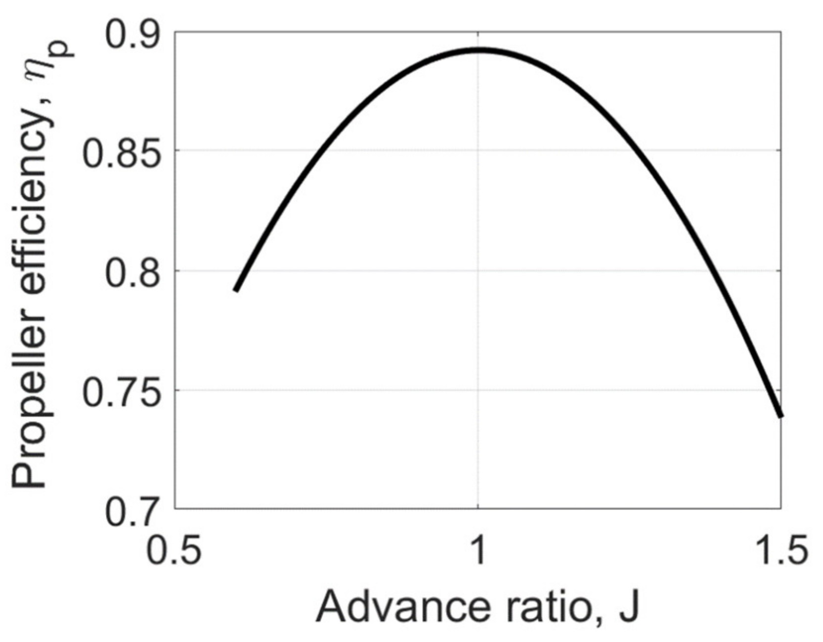
Another aspect to consider in an HEPS is the different interactions between the engine and the propeller. A fixed-pitch propeller works at high efficiency in a very limited operating range, and the engine speed is proportional to the propeller rpm. High-pitch propellers are usually employed to improve efficiency during cruise [
16] because this is the longest phase of flight and the most relevant for fuel consumption. However, as pointed out by Ma et al. [
17], if a fixed-pitch propeller is optimized for the cruise, its efficiency during the climb phase is low, leading to a higher power demand that in turn results in additional power requirements for the propulsion system and higher takeoff weight. Moreover, the engine efficiency is limited in a conventional power system by the need to follow the speed and torque demand of the propeller. In particular, the engine works at partial load during the cruise and the final part of the flight (descent). In a hybrid electric power system, the engine working points can be decoupled from the propeller demand, thus ensuring higher efficiency in the whole mission.
Even if few studies can be found in the literature about safety in ultralight aviation [
18], this is an open and concerning issue. According to the study by De Voogt et al., more than 20% of the accidents that occurred in Portugal, the USA, and the UK in the period 2000–2010 to ultralight vehicles were caused by engine failure [
19]. Most, if not almost all, accidents in ultralight aviation occur during the climb and are caused by malfunctions of the internal combustion engine. If the engine is not able to power the ultralight vehicle, stall conditions are generated and the lift generation is compromised. During the climb, the maneuvering capacity is very limited because the altitude separating the aircraft from the ground at that moment is quite low, and, consequently, the airplane crashes.
The hybridization proposed in this investigation has the main purpose of improving safety conditions and ensuring the possibility to continue climbing in purely electric mode. A second but not marginal goal of the investigation is to use relatively cheap mass production technologies derived from the automotive field.
The novel contribution of this investigation to the scientific literature is twofold:
- -
It proposes a power-split configuration with a Wankel engine for ultralight aircraft.
- -
The hybrid power system is primarily developed to increase safety, not to reduce fuel consumption or to increase endurance.
A new rule-based energy-management strategy is also proposed for this power system.
The paper is organized as follows.
Section 2 introduces the different architecture for electric hybridization and explains the choice of the power split or series/parallel configuration.
Section 3 presents the reference vehicle, the simulation approach, and the models adopted for the fixed-pitch propeller and the original piston engine. The sizing of the new powertrain according to the goals and the constraint of the specific application is explained in
Section 4. This section also describes the map-based model of the converters (the Wankel engine and the electric machines) and the equivalent electric circuit representation of the battery. Moreover, the rules of the proposed heuristic energy management strategy are explained in this section as well.
Section 5 shows the preliminary results in terms of performance and fuel consumption of the proposed power system compared with the original configuration and a non-hybrid Wankel powertrain. These results are discussed in
Section 6.
2. Review of Hybrid Electric Configurations for Light Aviation
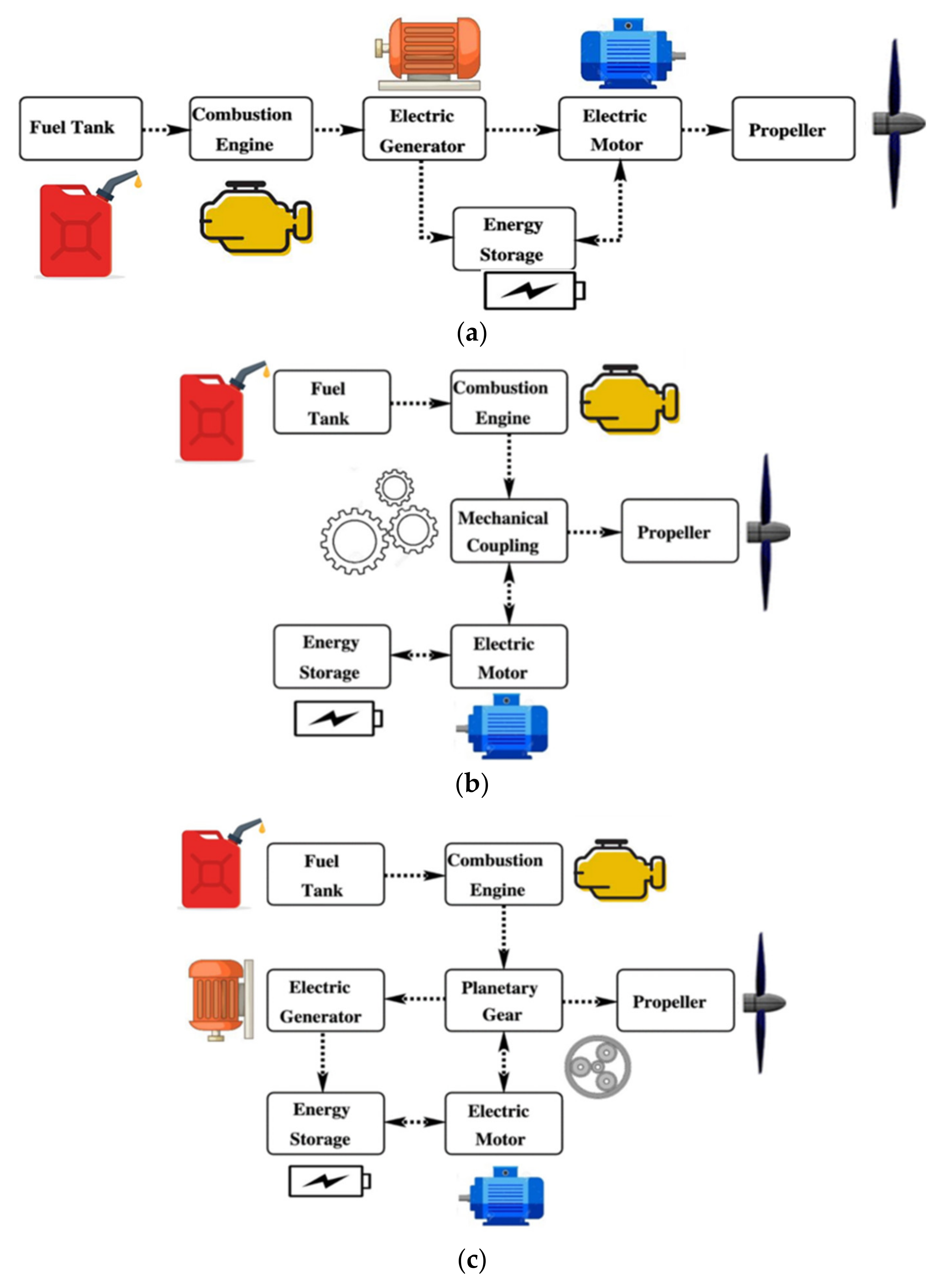
Hybrid electric power systems can be classified according to their configuration in parallel, series, and series/parallel [
6] as shown in
Figure 1. In a series Hybrid Electric Vehicle (HEV), the propulsive power is generated by an electric machine (motor) that receives electric power from the battery and/or a second electric machine (generator) run by an internal combustion engine. Thus, there is an electrical summation of power coming from the generator and the battery. The efficiency of a series hybrid is negatively affected by the two energy conversions, mechanic-to-electric (in the generator) and electric-to-mechanic (in the motor) [
20]. Moreover, it requires a large-size electric machine to be connected to the output shaft. In a series hybrid electric power system, there are two degrees of freedom: the split of electrical power between the battery and the generator and the engine rotational speed. An example of a series configuration for ultralight aviation is the Pipistrel Panthera [
21].
In parallel systems, there is a mechanical sum at the transmission level of the torque of the engine and the electric machine. The only degree of freedom in a parallel configuration is the torque split between the engine and the motor while the rotational speed of both converters is linked to the output shaft speed. An example of parallel configuration is Ampaire EEL [
22]. Harmon [
23] and Hiserote [
24] considered parallel configuration as the most practically realizable. A parallel hybrid electric system for a UAV with a Wankel engine is proposed in [
25]. Works in the scientific literature showed that parallel configurations can increase aircraft climbing performance up to 56% [
26] while decreasing fuel consumption by 6% [
6], with only 5% more weight compared to the non-hybrid system. In the case of failure of one of the propulsion units, in the parallel configuration, it is possible to de-couple the combustion drivetrain or shut down the electric power supply [
27], provided that the power delivered by the single unit is sufficient to move the propeller. Unfortunately, most of the accidents in ultralight aviation take place during takeoff and climb, when the power request is highest [
28,
29]. Therefore, accurate sizing of the components is required to ensure safety.
A series/parallel powertrain (also called power-split) is composed of two parallel power sources connected to the powertrain: one is the combination of engine and generator (
EM1) using a planetary gear set to connect each other, and the other one is the electric drive system which contains a motor (
EM2) and a battery. The disadvantages of this system in the automotive application are not only the need for two electric machines but also noise, vibration, and harshness [
30] because of the alternatively starting and stopping of the engine. These disadvantages are less important in the aerospace field because of the more regular power request profile.
The series/parallel configuration eliminates the mechanical link between the engine and the propeller (which is the limit of the parallel system) making it possible to optimize the engine operating point in terms of speed and torque, like in a series system but with a smaller size of the converters than a series configuration. This system can work in all-electric mode to achieve zero emissions for a limited range, in series mode at low speed and power request (since the engine speed is independent of vehicle speed), and in parallel mode at higher load and speed. It is also possible to perform parallel and series charging and to allow regenerative braking in the case of automotive applications [
31].
A typical design for a Series/Parallel Hybrid Electric Vehicle (SPHEV) is the Toyota Hybrid System (THS), which uses a planetary gearset to couple the engine and the two electric machines [
32]. This system is also called electric variable transmission because the engine speed and torque can be freely assigned by controlling the two electric machines and the engine operating points can be chosen in the high-efficiency region [
33]. The THS is very simple, using only one planetary gear and no clutches in the power flows.
In the present configuration, a series/parallel hybrid electric system is considered because of its flexibility and the lack of investigation about this kind of system in the aeronautical field.
4. The Series/Parallel Hybrid Electric Powertrain
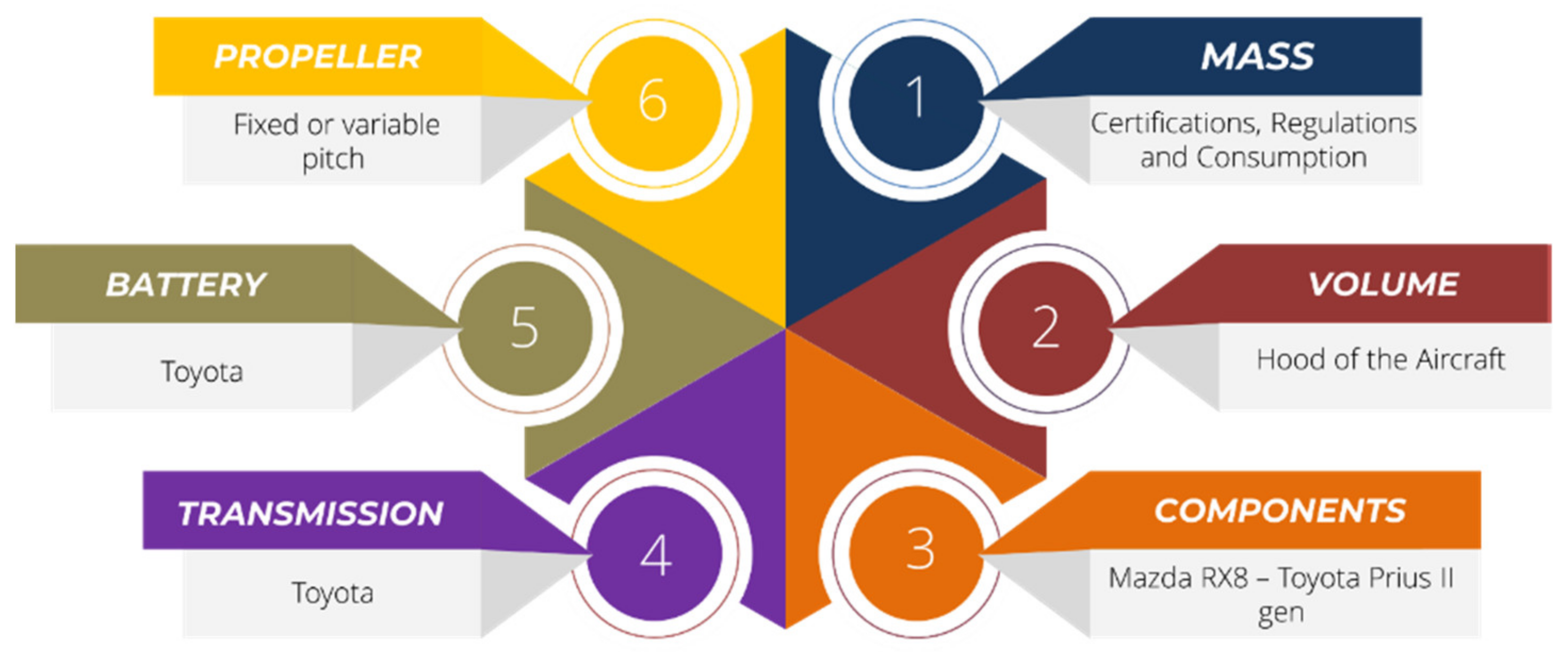
The choice of the components for the new hybrid electric powertrain was performed with the constraints shown in
Figure 6.
4.1. Sizing
Mass is a key factor that directly affects the consumption of the aircraft, as well as the standards to be met to obtain airworthiness certifications. The DPR 133 of 2010, which regulates and legalizes ultralight flight in Italy, requires that ultralight aircraft with a takeoff mass of less than 450 kg must comply with standards other than those with a takeoff mass of between 450 and 600 kg [
1].
The available space or volume is another important constraint, as the application studied must be implemented not only on the reference aircraft but on the entire air fleet of Promecc Aerospace s.r.l. For this reason, the proposed propulsion system will be designed to be as compact as possible so that it can be housed completely inside the engine hood of the aircraft without the battery and inverter that will be incorporated inside the fuselage.
The availability of components was another important constraint. The components of the hybrid propulsion system have been chosen from established technologies in the automotive field, such as the Wankel MAZDA13B engine used in the Mazda Rx8 and the electric machines taken from the second-generation Toyota Prius.
The Wankel engine was chosen for its high power–weight ratio, its simple design, and its low maintenance cost. This engine belongs to the category of rotary engines because the thermodynamic cycle is not obtained from the reciprocating movement of a piston in a cylinder, but from the rotation of an eccentric rotor within an epitrochoidal housing. The four stages of intake, compression, ignition, and exhaust occur at each revolution of the rotor at each of the three rotor faces, enabling the three power-pulses-per-rotor revolution. Another important feature of this kind of engine is the absence of intake and exhaust valves because the geometry and kinematics of the machine allow gas porting. Because of the reduced number of moving parts, the Wankel engine is less expensive and more reliable than piston engines, while the rotary kinematics reduces noise and vibrations. On the other hand, the large surface-to-volume ratio and slow rotation of the rotor chamber (one-third of the eccentric shaft speed) intensify the wall heat flux and reduce the thermal efficiency of this engine. The studies of Varnhagen et al. [
43] have put into evidence that hybridization, especially in a series configuration, can overcome the problem of low efficiency and take advantage of the higher power per unit of weight of this type of engine. The engine hood of the reference aircraft does not allow the complete housing of the MAZDA 13B engine, as it is too heavy and bulky. For this reason, the engine was modified by eliminating a rotor.
The electric machines of the second-generation Toyota Prius [
44,
45,
46] are asynchronous electric brushless machines of 30 and 50 kW, respectively. These electric machines have been chosen because they are very compact and light. Together these technologies perfectly respond to the power demand of a typical flight mission for ultralight aircraft, as shown later in the paper.
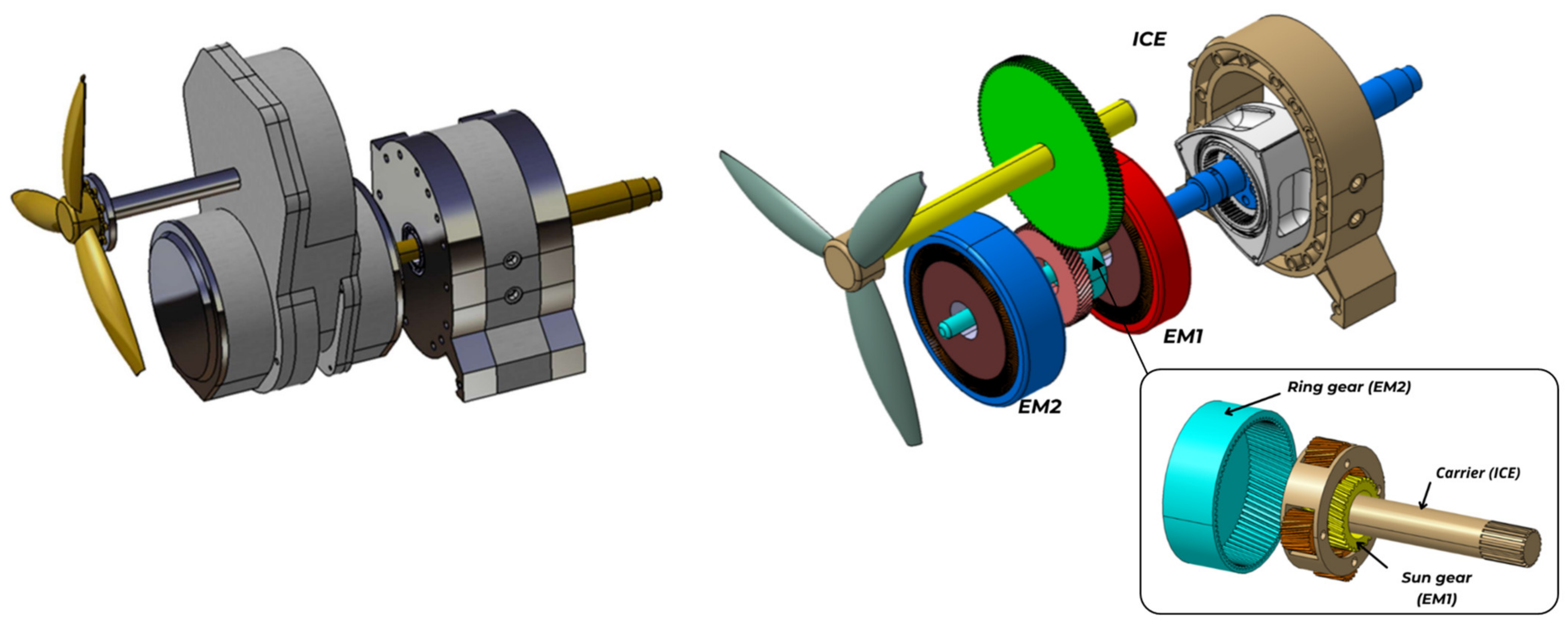
The replacement of the Rotax engine also results in the loss of the final power transmission mechanisms. In fact, the Power Split Device (PSD) of the Toyota Prius was used to mechanically connect the thermal engine and the electric machines.
A planetary gear set has three main rotating parts: the sun, the ring, and the carrier. Each of them can be connected to the input shaft, and the output shaft, or can be held stationary. In particular, the PSD connects the electric machine EM2 with the ring of the planetary gear, the electric machine EM1 with the sun, and finally the carrier with the internal combustion engine. , and are the symbols used to denote the number of teeth of the ring gear, the sun gear, and each planet gear, respectively.
Therefore, the following relation is established between the speed of the three converters (the engine and the two electric machines):
Thanks to this system, it is possible to adapt the rotation speed of the EM1 electric machine to obtain the desired rotation speed of the engine (.
Once the torque delivered by the engine has been set, the following will be determined:
The torque transmitted to the ring,
, is:
Finally, the power transmitted to the propeller shaft is:
As already explained, in addition to the mechanical connection, this technology also allows the engine to work efficiently. This can be achieved by varying the rotation speed of the generator connected to the solar shaft of the planetary gear according to the power demand. Note that EM1 can work as a starter for the internal combustion engine; thus, the original engine starter is no longer required.
The battery has been obtained from the Toyota Prius and is accompanied by its electronics already pre-configured to communicate with the selected electric machines. Although the cells are of the NiMH type, the use of this battery allowed us to reduce not only the costs but also the design efforts resulting from the sizing of the battery itself and the identification of the model at a commercial level. However, a lithium-ion battery will be considered in the future to reduce the takeoff mass.
The power-split hybrid propulsion system is shown in
Figure 7 and described in detail in
Table 3.
Each component is retrieved together with its component-based controller. Therefore, the engine is considered inclusive of an ECU (Engine Control Unit), the electric machines are acquired together with their drivers, and the battery is equipped with its BMS (battery management system).
4.2. Models
Like in the case of the baseline configuration, a backward approach is used to define the working points of the components of the propulsion system after calculating the mechanical power required by the propeller and the corresponding speed, , from the propeller line. A load-independent efficiency of 0.95 was assumed for the PSD.
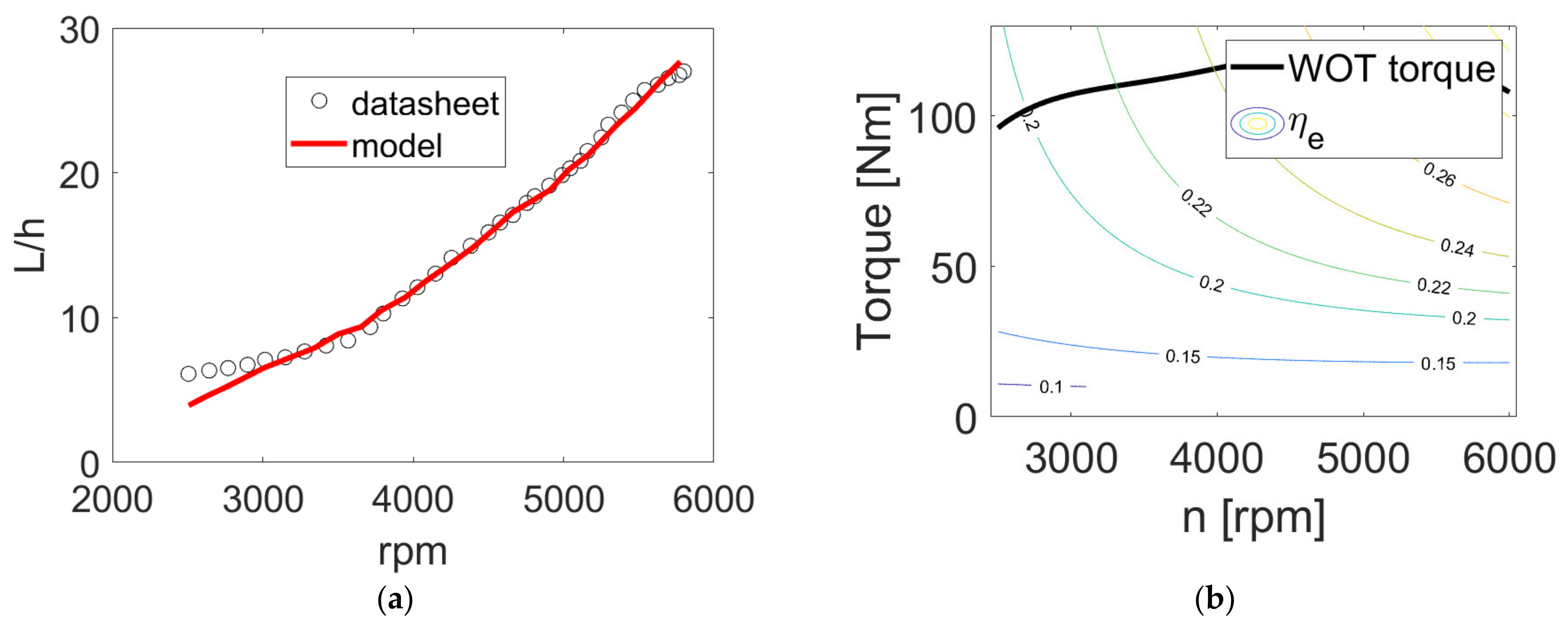
Despite the differences with piston engines, the fuel consumption of a Wankel is a function of torque and speed like in a piston engine; therefore, the two engines can be modeled with the same kind of models. However, in this case, it was not necessary to develop a Willans line model because the map of the two-rotor Mazda 13B was available [
47].
To obtain the map of the single-rotor Wankel engine, the concept of scalability was used. In a reciprocating engine, the torque is linearly proportional to the displacement, if the effect of displacement on volumetric and brake efficiency can be neglected [
11,
38]. This reasoning has led to the development of scalable piston engine models that assumes that two engines have the same efficiency map in terms of bmep and speed, provided that the original and scaled engine use the same technology [
11]. In the case of the Wankel engine, since the engine has a modular nature and each rotor behaves like an independent unit [
47], the hypothesis of scalability is valid even more than in the case of piston engines. Taking into account this scalability, the map of the downsized engine was derived by simply halving the torque in each point of the efficiency map of the two-rotor Maxda 13B engine reported in [
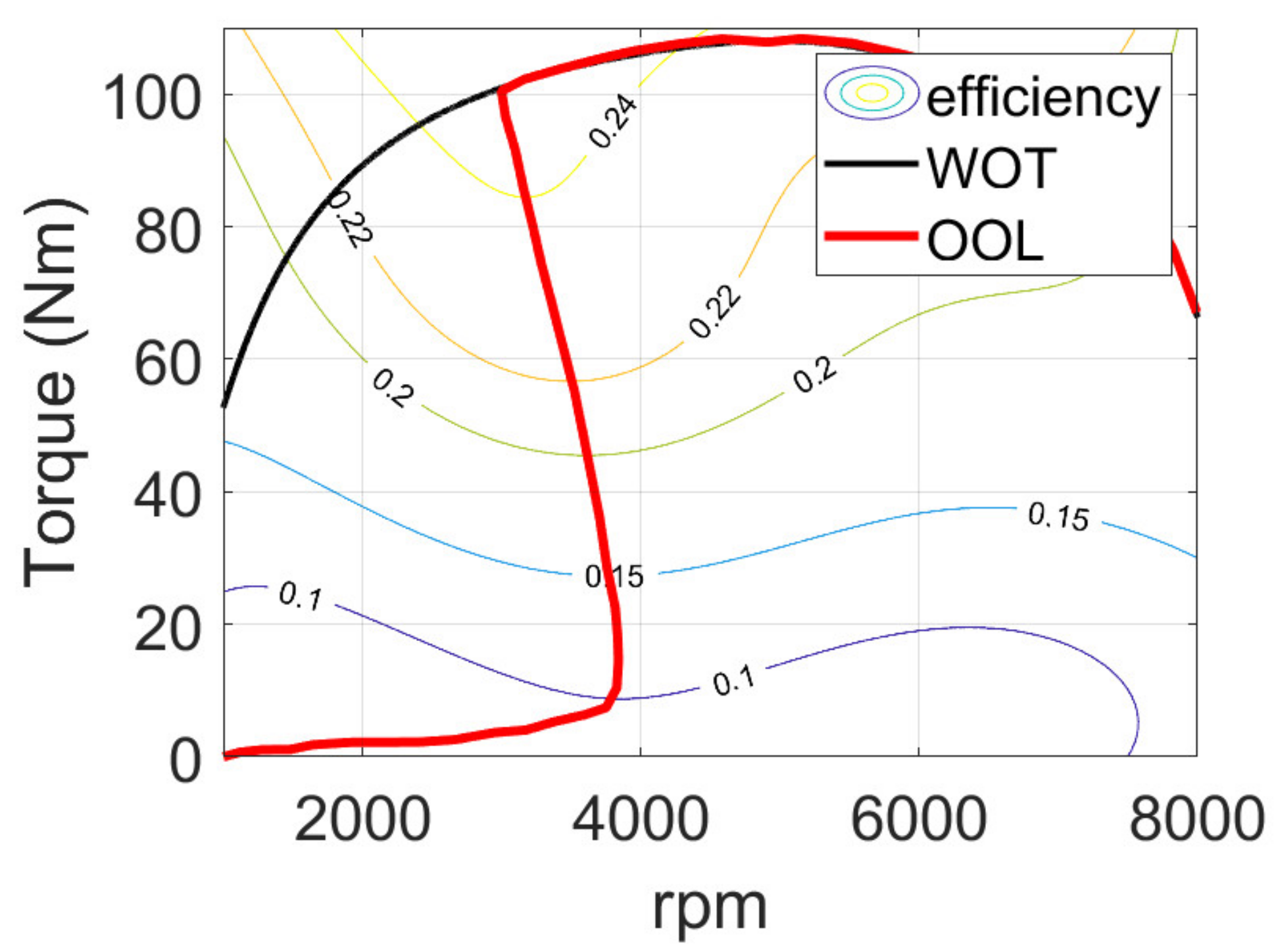
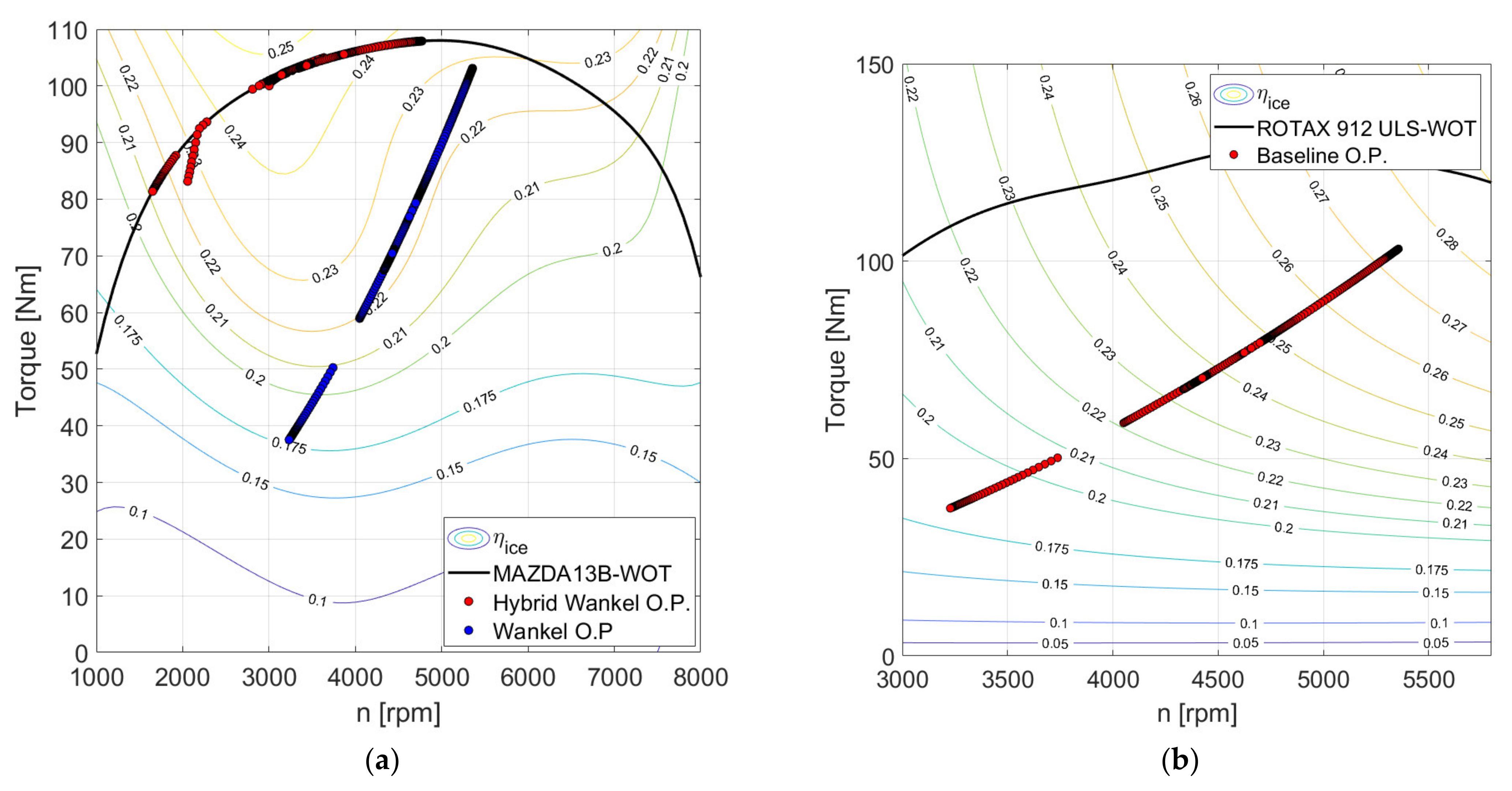
48]. The resulting efficiency map of the single-rotor Wankel engine is reported in
Figure 8. The efficiency of the engine is calculated during the simulated mission by interpolating this digitalized map.
Figure 8 reports the Optimal Operating Line (OOL) as well. The OOL is a smooth line collecting all the torque and speed combinations that, for a specific power request, guarantee the minimum fuel consumption in steady-state conditions [
40]. The availability of this curve is essential for the proposed energy management strategy as explained in the following sub-section.
The electric machines (Brushless DC) were obtained from the Toyota Prius as already explained. For the preliminary analysis performed in this investigation, both machines were simulated with a simple Willans line approach as suggested by [
11]. As a further development, the maps available in the scientific literature [
44,
45] will be digitalized and used for detailed simulations.
The NiMH battery is simulated with a simple equivalent circuit model where the open-circuit voltage and the internal resistance depend on the state of charge as reported in [
49], while the temperature dependence is neglected. The battery state of charge is calculated with the coulomb counting method [
11].
4.3. Energy Management
As explained in the introduction, there are two levels of control in an HEPS, supervisory and component-based. In this work, only the supervisory level is considered. The supervisory controller is assumed to pass the setpoints to the ECU, the BMS, and the drivers of EM1 and EM2 that will control each component to meet the desired set-point.
In the present investigation, the set points are decided by a rule-based heuristic energy-management strategy. The main goal of the strategy is to make the Wankel engine work at the best possible efficiency while keeping the battery at the desired state of charge and verifying that the battery and the electric machines work within their technological limits. The proposed EMS is explained below.
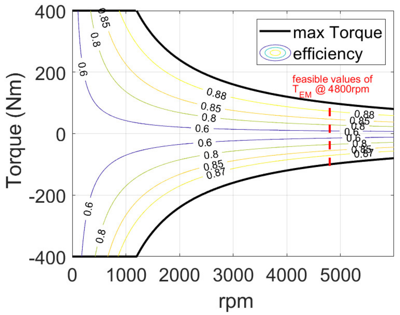
The main input to the strategy is the rotational speed of the electric machine
EM2, which is calculated as:
where
is the final gear ratio.
Given the rotation speed
, using the map of the
EM2 machine, it is possible to evaluate the range of possible torque values
that can be delivered at that rotation speed, as illustrated in
Figure 9 with reference to 4800 rpm (chosen as an example).
Accordingly, the torque to be transmitted from the ring gear must be in the range
, and the torque of the engine and electric machine
EM1 must be in the ranges
and
, respectively.
This reasoning allows the EMS to identify a feasible zone in the engine map delimited by the torque range
, the engine WOT curve, and the constraints
to avoid low-efficiency zones (see
Figure 10).
Among all the possible points in this area, the first points to be investigated are those belonging to the OOL, starting from the highest efficiency one. Then, from Equation (10), the corresponding speed of the generator is obtained, and a check is performed to verify that the working point of the EM1 is feasible. If not, the engine working point is changed, trying to remain on the OOL. If the calculation procedure on the OOL points does not converge to a solution, the solution will be sought outside the OOL but always in the research space. If no feasible solution is found on the OOL, the research space is expanded, including areas of the Wankel engine map with higher values of specific consumption.
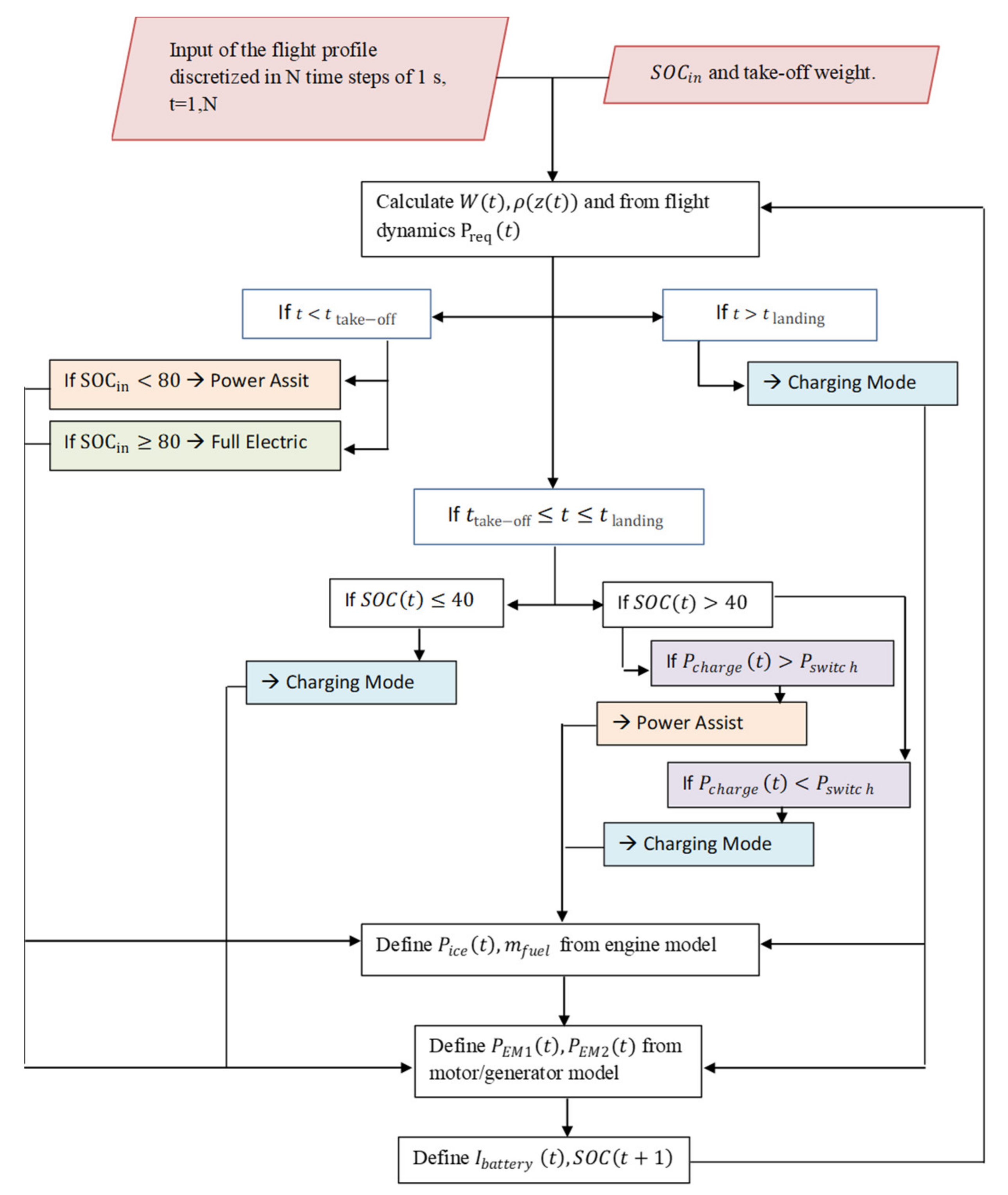
The energy management strategy also considers the state of charge of the battery as explained in
Appendix A.
6. Discussion
This investigation deals with a series/parallel configuration, which is neglected in the literature on the hybridization of aerial vehicles because of its complexity [
9] and shows that this configuration is compatible with the stringent constraints of ultralight aviation. Moreover, the proposed HEPS is able to exploit the synergy with Wankel engines that are characterized by a higher power-to-weight but lower peak efficiency than piston engines.
In addition, this work underlined the possibility of employing hybridization to improve safety in ultralight aviation by reducing the possibility of accidents due to engine failure. The proposed power system can deliver up to 80 kW (30 kW from EM1 and 50 kW from EM2) in continuous operation (independently of the flight altitude) but both machines can deliver higher peak power for a short period, so very high performances can be obtained. The results of this preliminary investigation show that the increase in safety during flight does not necessarily imply an increase in aircraft costs. The use of automotive components, once retrofitted, would allow the reuse of mechanical and electrical components that otherwise should be disposed of. This will not only reduce costs and emissions when the aircraft is in flight but also from a life-cycle-assessment point of view.
Depending on whether the takeoff mass is lower or higher than the threshold value (450 kg), the Italian legislation [
1] requires different technical specification to be met by ultralight aviation. Moreover, different flight test procedures are required for the two classes of vehicles. Therefore, a more detailed evaluation of the final mass of the vehicle is needed, since the Freccia with the new powertrain would exceed 450 kg. Since the battery is the most critical component from this point of view, future development will deal with the redesign of the battery. Moreover, the possibility to reduce the fuel tanks by exploiting the better fuel economy of the HEPS will be considered. Note that the Italian legislation was changed during the development of the present project from [
1] to [
2] so this issue could not be fully addressed here.
Future studies will concentrate also on the comparison of the proposed HEPS with a piston-engine configuration with a constant-speed propeller. Constant speed is a solution adopted in conventional configurations to improve fuel consumption at the expenses of higher costs and assembly problems caused by propeller-speed control units.
The results of this investigation are based on several simplifications about the weight and the performance of the proposed system and some quite arbitrary assumptions about the flight conditions of the vehicle. In addition, the level of accuracy of the models adopted in this study is reasonable but limited. In addressing the control of the propeller speed, it will be necessary to develop dynamic models or at least suitable transfer functions that take into account the shaft inertia in order to evaluate the throttle response of the whole HEPS [
50].
Finally, the improvement in fuel economy obtained with the proposed HEPS and EMS is quite satisfactory and in line with the results presented in the literature. Nevertheless, it could be interesting to compare the proposed heuristic energy management strategy with more advanced techniques [
9,
10,
14,
15].


