Abstract
Dynamic substructuring methods are initially developed for time-invariant systems to evaluate the dynamic behavior of a complex structure by coupling the component substructures. Sometimes, the component substructures change their position over time, affecting the dynamics of the entire structure. This family of problems can be tackled using substructuring techniques by isolating the time dependency in the coupling conditions among the time-invariant substructures. Mechanical systems, composed of subsystems in relative motion with a sliding interface, can be analyzed using this approach. In previous work, the authors proposed a solution method in the time and frequency domain using this approach under the assumption that the relative sliding motion at the contact interfaces is a-priori known, at least approximately. This assumption implies that the perturbation generated by the friction-induced vibration is neglected. In subsequent work, a more realistic contact assumption was considered to account also for the local vibration of the contact point and the geometric nonlinearity due to the elastic deformation. In this paper, a simplification with respect to the realistic contact assumption is introduced, which neglects the angular variation of the direction normal to the contact interface. The simplified approach is advantageous because it is equally able to highlight the occurrence of friction-induced instabilities, and it reduces the computational burden. The results of the substructuring methods using different contact assumptions are compared with those of a reference numerical method to show how the choice of the contact algorithm allows for tackling a wide range of operating conditions, from simple position-dependent problems up to complex friction-induced vibration phenomena.
1. Introduction
In complex mechanical systems, contact and friction forces arise at the contact interfaces among components in relative motion. These forces can cause the so-called friction-induced vibrations (FIV) [1,2]: a vibrational response of the system that can affect the structural integrity and comfort [3].
Contact problems could be tackled using the dynamic substructuring approach [4,5,6], considering each body in contact as a single substructure. In fact, the dynamic substructuring allows for predicting the dynamic behavior of a complex mechanical system, knowing the dynamic behavior of its component subsystems [7,8].
Although the classical substructuring approach assumes that the system is time-invariant, time-variant systems composed of time-invariant substructures subjected to time-variant coupling conditions have been tackled with this approach [9,10,11]. Configuration-dependent problems can be numerically analyzed in the framework of dynamic substructuring providing interesting results and reducing the computational effort. For sliding contact problems with friction, equilibrium conditions apply in the tangential directions at the contact interface that are not considered in the compatibility conditions because of sliding. This discrepancy represents a non-collocated interface as defined in [6,12].
The approach presented in [11] assumed that the time-variant compatibility and equilibrium conditions arising from sliding contact are a-priori known. The basic contact assumption made in [11] accounts for relative sliding due to the kinematic boundary condition. Still, it is not able to consider the relative displacement caused by the system deformation on the contact interface. System deformation and local vibrations at the contact are relevant for dynamic contact problems [13] and are the main cause of friction-induced vibrations phenomena such as dynamic instabilities [14,15,16], stick-slip [17,18] or sprag-slip [19,20]. These phenomena can produce adverse effects, such as the squeal noise [21,22], or positive effects, for example, in harvesting applications [23] and health monitoring applications [24].
For this reason, the authors proposed an enhanced substructuring method based on a realistic contact assumption that provides a more reliable definition of compatibility and equilibrium conditions [25]. In this case, the deformation of the bodies in contact is considered, including geometric nonlinearities, to define the time-variant coupling conditions.
In this paper, a simplification with respect to the realistic contact assumption is introduced that neglects the angular variation of the direction normal to the contact interface. Generally, the variation of the direction normal to the contact interface is not relevant for vibrating systems with sliding contact interfaces. It can be neglected, thus simplifying the mathematical formulation of the time-variant coupling conditions. The variation of the direction normal to the contact could become more significant during friction-induced instabilities. However, one may be more interested in determining the conditions for the onset of the instabilities, much more than accurately describing the limit cycle.
Substructuring methods using different contact assumptions are applied to evaluate the response of a beam on beam system [26]. In particular, the results are compared with those of a numerical reference method [27] to show how the choice of the contact algorithm allows for tackling a wide range of operating conditions, from simple position-dependent problems up to complex friction-induced vibration phenomena.
2. Numerical Methods for Contact Dynamic Analysis
This section presents two different approaches to investigate the dynamic response of systems composed of different bodies in frictional contact. The mutual interaction can give rise to friction-induced vibrations. A well-known numerical approach [27] is described and used as a reference. Results are compared with those of the substructuring-based methods developed by the authors and detailed in [11].
2.1. Forward Increment Lagrange Multiplier Method
The method proposed by Carpenter et al. in [27] is a very efficient numerical method to simulate the dynamic response of a mechanical system with a frictional contact interaction among different parts. It employs the explicit integration scheme proposed by Newmark [28] to evaluate a predictor of displacements at a given step without accounting for contact. When predicted nodal positions show a compenetration, Lagrange multipliers are introduced on contact nodes to correct the nodal displacement. The first correction is computed, supposing a sticking contact. Still, if the calculated friction forces exceed the sticking limit, relative sliding between parts is allowed, and friction forces are those due to sliding. Hence, the correct displacement is evaluated by using a Gauss-Seidel iterative procedure.
2.2. Substructuring with Time-Variant Coupling Conditions
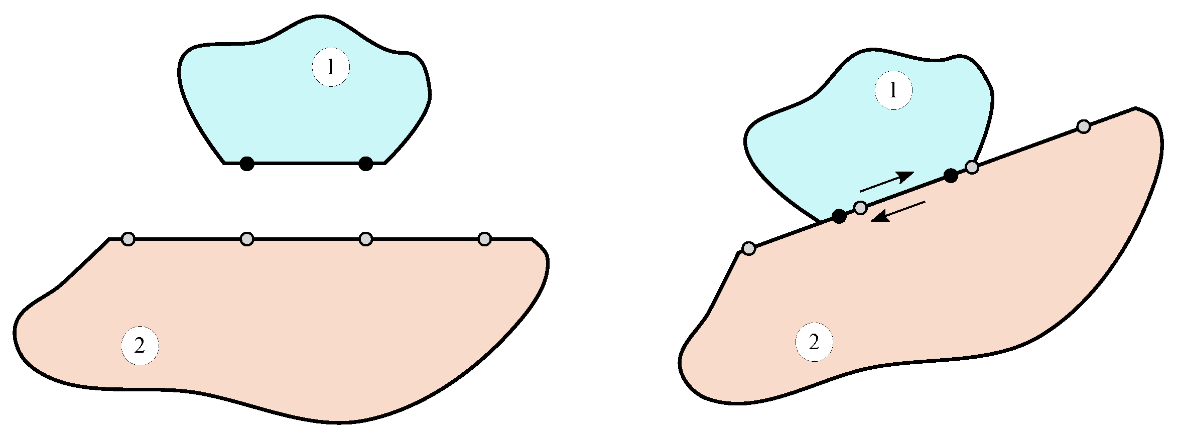
Contact problems are intrinsically suitable to be investigated using dynamic substructuring. In fact, the system is generally composed of different subsystems, as shown in Figure 1 and their contact interaction could be defined in the substructuring framework.
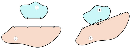
Figure 1.
Schematic of contact problem in the substructuring framework. Left: Substructures 1 and 2. Right: Substructures 1 and 2 in relative sliding.
A contact problem can be represented as a system formed of n interacting subsystems. For the single linear subsystem r, the equation of motion can be expressed as:
where:
- are the mass, damping and stiffness matrices of subsystem r;
- is the vector of displacements of subsystem r;
- is the vector of external forces on subsystem r;
- is the vector of connecting forces with other subsystems (internal constraint forces).
Before considering the contact interaction, the equation of motion of the n independent subsystems can be written as:
where , and are block diagonal matrices.
For contact problems, compatibility and equilibrium do not necessarily apply to the same set of DoFs. In fact, if sliding with friction occurs, the compatibility applies only in the direction normal to the contact interface (no penetration), while equilibrium of tangential and normal forces must be imposed. Moreover, due to the relative displacement between subsystems, compatibility and equilibrium conditions change over time.
A given pair of matching DoFs at time t must share the same displacement to ensure compatibility [11]. This condition can be expressed as:
where each row of enforces compatibility between a pair of matching DoFs at time t.
Internal constraint forces apply only to connecting DoFs. The sum of internal constraint forces must be zero at any pair of matching DoFs at time t to ensure the equilibrium [11]. The resulting set of equilibrium conditions can be written as:
Using the set of the three previous equations (the so called three field formulation):
it is possible to include contact problems in the substructuring framework. Note that, when sliding occurs at the contact interface, and become time-dependent.
The substructuring problem can be solved by automatically satisfying the equilibrium condition; this can be obtained by defining a unique set of Lagrange multipliers corresponding to connecting force intensities:
Note that, when friction forces are present at the interface, the matrix is different from the matrix previously defined to enforce the compatibility condition [25].
In this approach, known as dual assembly, each interface DoF is considered as many times as there are substructures connected through that DoF.
The interface equilibrium condition (4) is thus written:
Since Equation (7) is always satisfied by any set of connecting force intensities , the system of Equation (5) becomes:
Equation (8) can be explicitly solved in the time domain using an approach similar to the one presented in [27], i.e., by relating compatibility at time with the dynamic equilibrium at time , where h is the integration time step. If both compatibility and dynamic equilibrium were considered at the same time instant, the problem would be singular. The equation of motion becomes:
where the subscripts n and refer to values at times and , respectively. The first equation of (9) can be recast as:
The previous equation can be explicitly integrated using the Newmark method [28], which reduces to the central difference scheme if .
The displacement can be obtained after introducing the central difference expression of into Equation (10) and by estimating as . can be split into a predictor , that can be immediately computed because it depends on the known displacements at times and , plus a corrector that accounts for the effects of the contact forces :
where
and
The corrector is unknown because contact forces must be estimated, and constraints must be defined. The amplitude of contact forces can be obtained by combining Equations (12) and (14) with the second line of Equation (9):
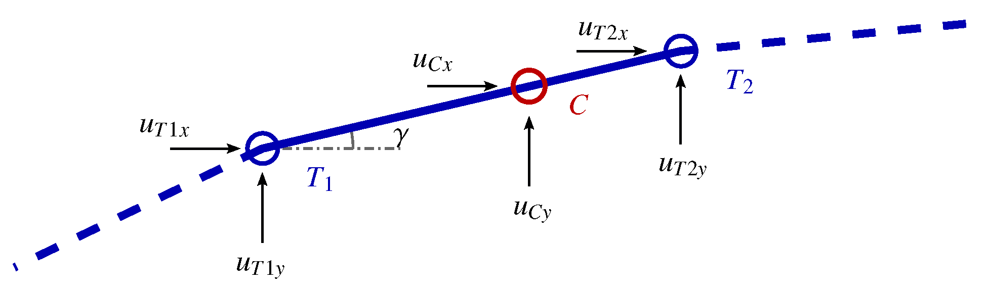
Contact forces depend on matrices and at time . In the following, the matrices and are expressed for the 2D contact problem between a point C (slave node) and a line segment (master element) belonging to two different bodies, as shown in Figure 2.

Figure 2.
Master element and slave node.
They can be evaluated through different assumptions:
- (a)
- A basic contact assumption, introduced in [11], based on the a-priori defined rigid motion between the component subsystems described by the kinematic boundary conditions (Subs-a). It is assumed that the body to which the slave node belongs moves with respect to the other body with a velocity . Hence, by using a master element-slave node approach, the position of the slave node C at time t can be expressed as:where is the initial position of the slave node.
- (b)
- A realistic contact assumption, introduced in [25], considers the deformation of the contacting bodies (Subs-b) to account for friction-induced vibrations. To estimate the position of the contact point, the system position at time is evaluated using the predictor of displacements defined in (13), i.e.:where represents the undeformed position.
- (c)
- A simplification with respect to the realistic contact assumption is considered that disregards the direction change of the contact force due to the deformation (Subs-c).
The position identifies the master element (see Figure 2) involved in the contact and the relative position of the slave node can be obtained as:
Note that depends only on the boundary conditions in case (a), while it accounts for system deformation in cases (b) and (c). In the latter cases, the coupling conditions depend on the system deformation and are able to describe the geometric nonlinearity of the coupled system.Moreover, the effect of vibrations on the tangential displacement of the contact point is included, thus allowing to deal with friction-induced vibrations.
In order to correctly define the friction forces direction, the sign of the relative velocity of the slave node C with respect to the oriented line segment is introduced:
The nonzero elements of matrices and can be generally expressed as [25]:
where is the friction coefficient. Here, it is supposed to be constant, but it can be considered dependent on the state of the system. Note that the angle between the x direction and (see Figure 2) is considered to be assigned in cases (a) and (b), while it is computed at each time step accounting for system deformation in case (c). In cases (a) and (b) if (i.e., aligned with the x axis), Equations (50) and (53) in [11] are re-obtained.
3. Results
In this section, the results of the transient simulations performed with the substructuring method, using the three different approaches listed above (Subs-a, Subs-b, and Subs-c), are compared with the results of the forward increment Lagrange multiplier method (introduced in Section 2.1 and referred as FiLm in the following) to highlight and discuss the pros and cons of each one.
3.1. Numerical Model
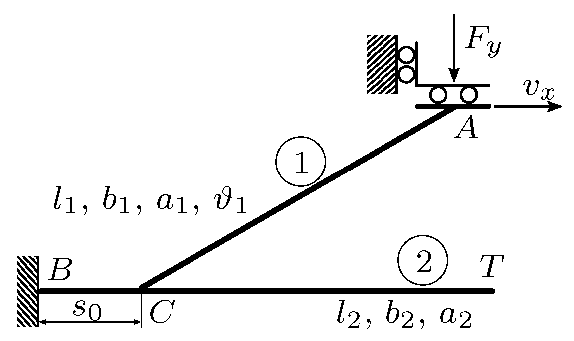
The mechanical system considered in this work is composed of two subsystems connected through a sliding interface with a constant friction coefficient . As shown in Figure 3, the subsystem 1 is an oblique beam that slides along the upper horizontal edge of a cantilever beam (subsystem 2). The oblique beam, of length and section , forms an angle with the horizontal beam, of length and section . The horizontal beam is fixed at its end B, while time-variant boundary conditions (vertical force and velocity ) are applied at the upper end A of the oblique beam. The contact point C, initially distant from the fixed end, moves to the right during the simulation. Geometrical characteristics, mechanical properties, and boundary conditions are reported in Table 1 and Table 2. Note that viscous proportional damping is considered in the model. The vertical load , the velocity , and the friction coefficient are applied smoothly during the first 0.1 s and then remain constant up to the end of the simulation. Moreover, to damp the transient vibrations generated by the horizontal acceleration and by the application of the vertical load, high damping coefficients ( and ) are used during the first 0.2 s and gradually reduced to the desired values and in the next 0.05 s.
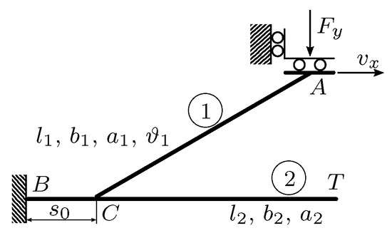
Figure 3.
Mechanical system used in the simulations.

Table 1.
Geometrical characteristics of the model.
Table 2.
Mechanical properties and boundary conditions of the model.
Each beam is modeled in ANSYS using plane-stress elements. To reduce the computational burden, a Craig Bampton reduction of each substructure is performed, retaining 20 fixed interface modes and a set of physical DoFs, including those on which the boundary conditions are applied and the ones involved in the contact (3 DoFs for the oblique beam and 200 DoFs for the horizontal cantilever beam).
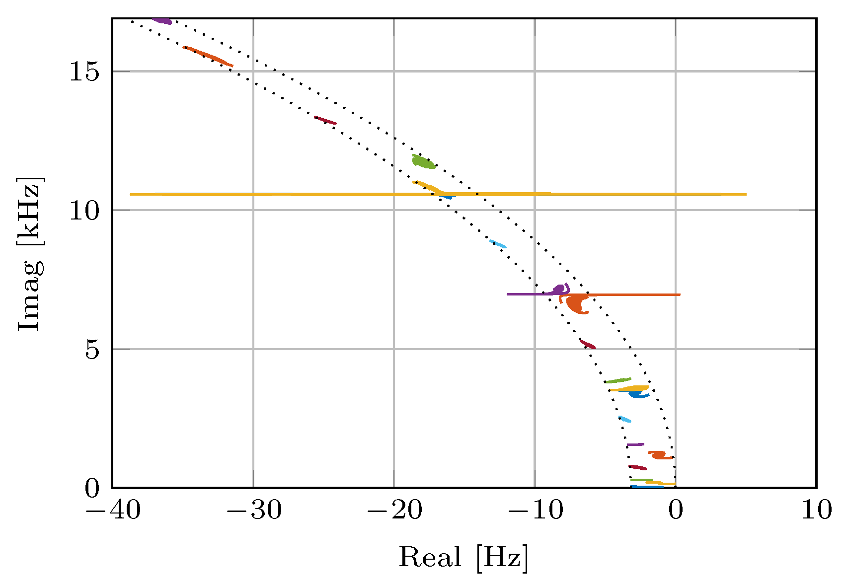
The value of the friction coefficient used in the simulation is chosen so that some instabilities due to modal coupling arise when the tip of the oblique beam moves along the upper side of the horizontal one. Figure 4 shows the locus plot of complex eigenvalues [11] of the coupled system when the oblique beam, starting from position , slides toward the free end of the horizontal cantilever beam. The locus plot is obtained by coupling the two substructures at every position using primal assembly, as proposed in [11]. Note that the real part of some eigenvalues becomes positive, giving rise to possible dynamic instabilities around 7 kHz and 10.5 kHz. When the system passes through an instability region, the vibration amplitude is expected to increase with an exponential law, while it is expected to decrease when the instability region is overcome.
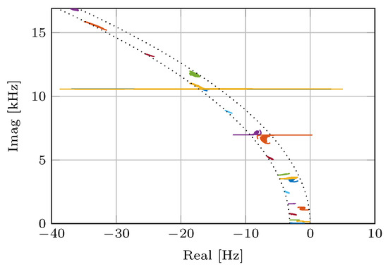
Figure 4.
Locus plot of the 20 lowest eigenvalues for a friction coefficient .
3.2. Subs-a and FiLm Comparison
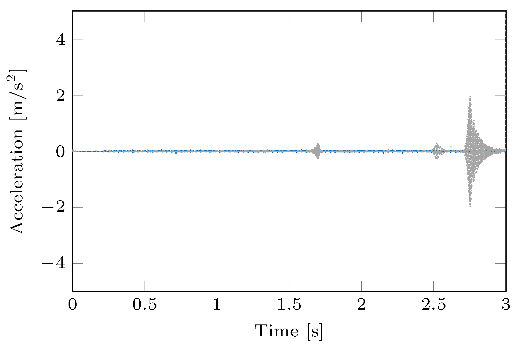
In this section, the results of transient simulation performed with the basic contact assumption Subs-a are compared with the results of the reference method FiLm. Figure 5 shows the vertical acceleration of the free end T of the horizontal beam evaluated using the two methods. Figure 6 shows the spectrograms of the vertical accelerations in Figure 5. The computational time required to obtain the solution using the Subs-a method is 68% of the time required by the reference method (2 h 53 min 54 s vs. 4 h 15 min 51 s on a Desktop PC with a 3.50 GHz quad-core CPU).
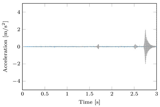
Figure 5.
Vertical acceleration of point T: comparison between  Subs-a and
  FiLm method.
Subs-a and FiLm method.
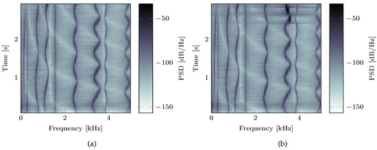
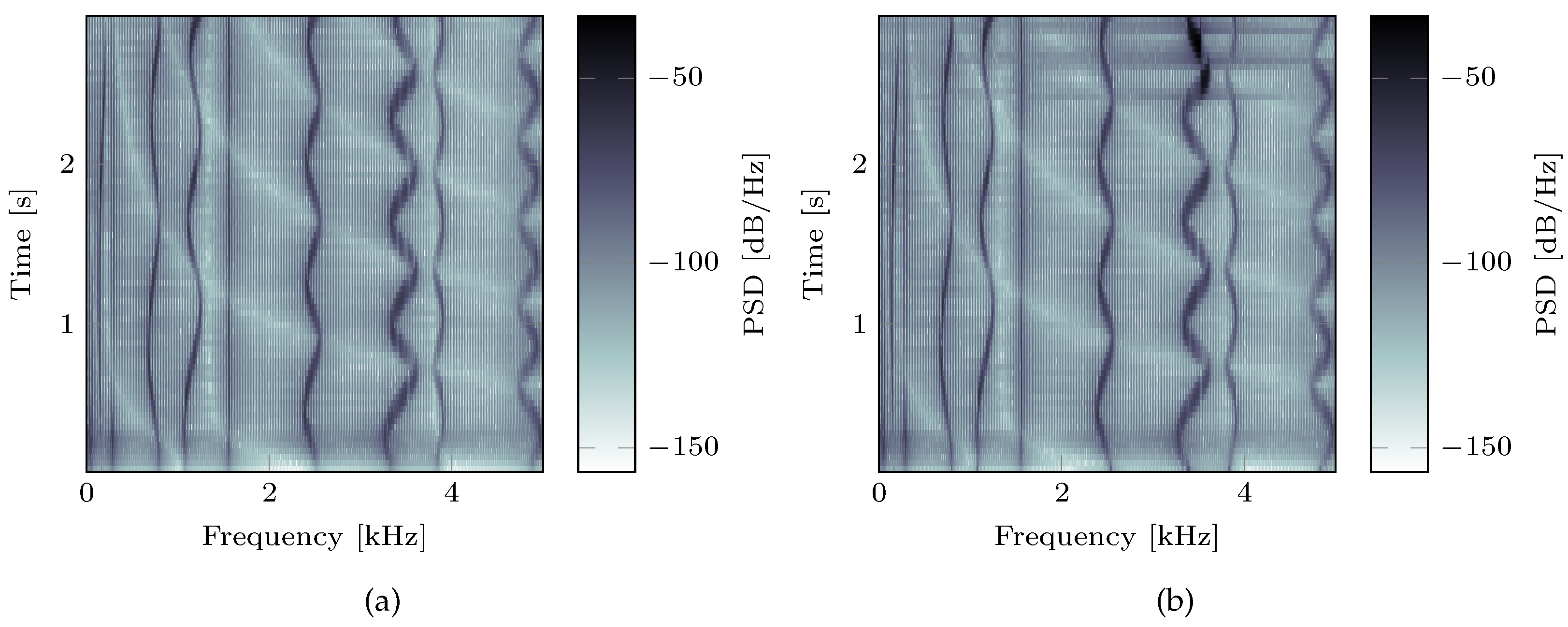
Figure 6.
Spectrograms of the vertical acceleration of point T obtained using the Subs-a (a) and FiLm (b) methods.
The FiLm method results show typical vibration bursts occurring when an unstable system configuration is crossed. On the other hand, the results obtained with the Subs-a method highlight that the method is not reliable in case of contact dynamic instabilities. However, it is capable of detecting the changes in the global dynamics of a time-variant coupled system. The authors already mentioned this limitation in [11]. It is due to the a priori definition of coupling conditions that do not account for sliding associated with static and dynamic body deformation. This is in fact a crucial aspect in order to reproduce unstable friction-induced vibrations since the energy absorption of the structural system depends on the phase shift between the oscillations of contact forces and relative displacement [29]. Therefore, a lack of precision in estimating these quantities can heavily affect the correctness of results. Thus, the realistic time-variant substructuring method Subs-b will be used in the following section.
3.3. Subs-b and FiLm Comparison
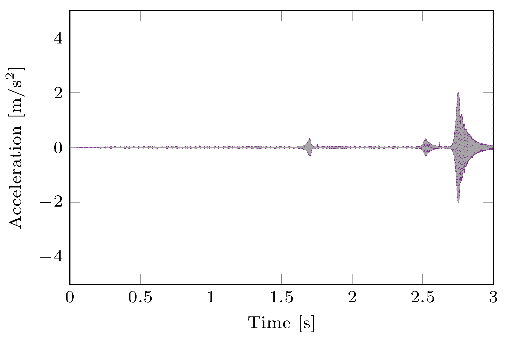
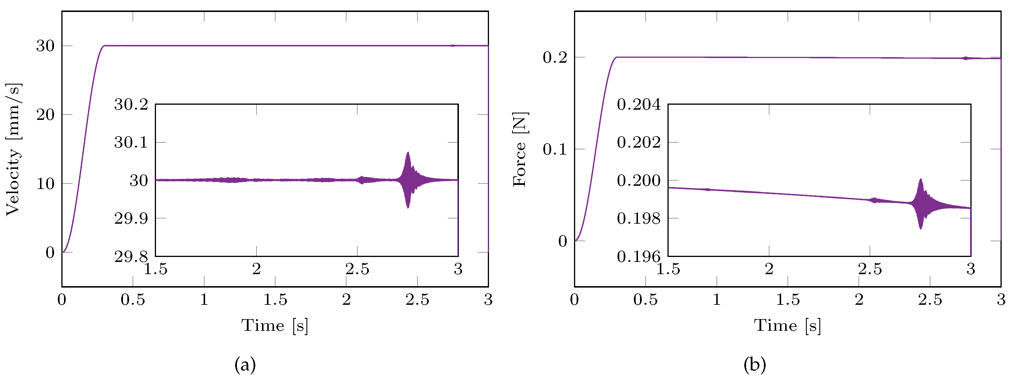
In this section, the results of transient simulation performed with the realistic contact assumption Subs-b are compared with the results of the reference method FiLm. Figure 7 shows the vertical acceleration of the free end T of the horizontal beam evaluated using the two methods. A substantial superposition of the two responses is observed, thus confirming the effectiveness of the Subs-b method also in retracing the friction-induced vibrations due to contact-induced instabilities. Figure 8 shows the horizontal velocity of point C and the normal contact force during the simulation with the Subs-b method. Results confirm the sliding contact assumption for all the simulation time. Note that the normal contact force decreases due to the deflection of the horizontal beam.

Figure 7.
Vertical acceleration of point T: comparison between  Subs-b and FiLm method.
Subs-b and FiLm method.
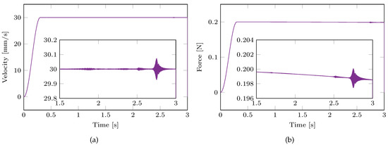
Figure 8.
Relative velocity (a) and normal contact force (b) for the Subs-b method.
In this case, the proposed method is computationally more efficient than the classical FiLm method: the computational time required by Subs-b is 74% of that required by FiLm. In fact, although the two subsystems are always in sliding contact, the FiLm method for each time step supposes that the bodies are in sticking contact, and, if the sticking condition is not verified, it relaxes the constraint along the tangential direction and approximates the correct position with an iterative procedure. On the contrary, the Subs-b method directly provides the correct solution at the subsequent time step, thus reducing the computational burden.
3.4. Subs-c and FiLm Comparison
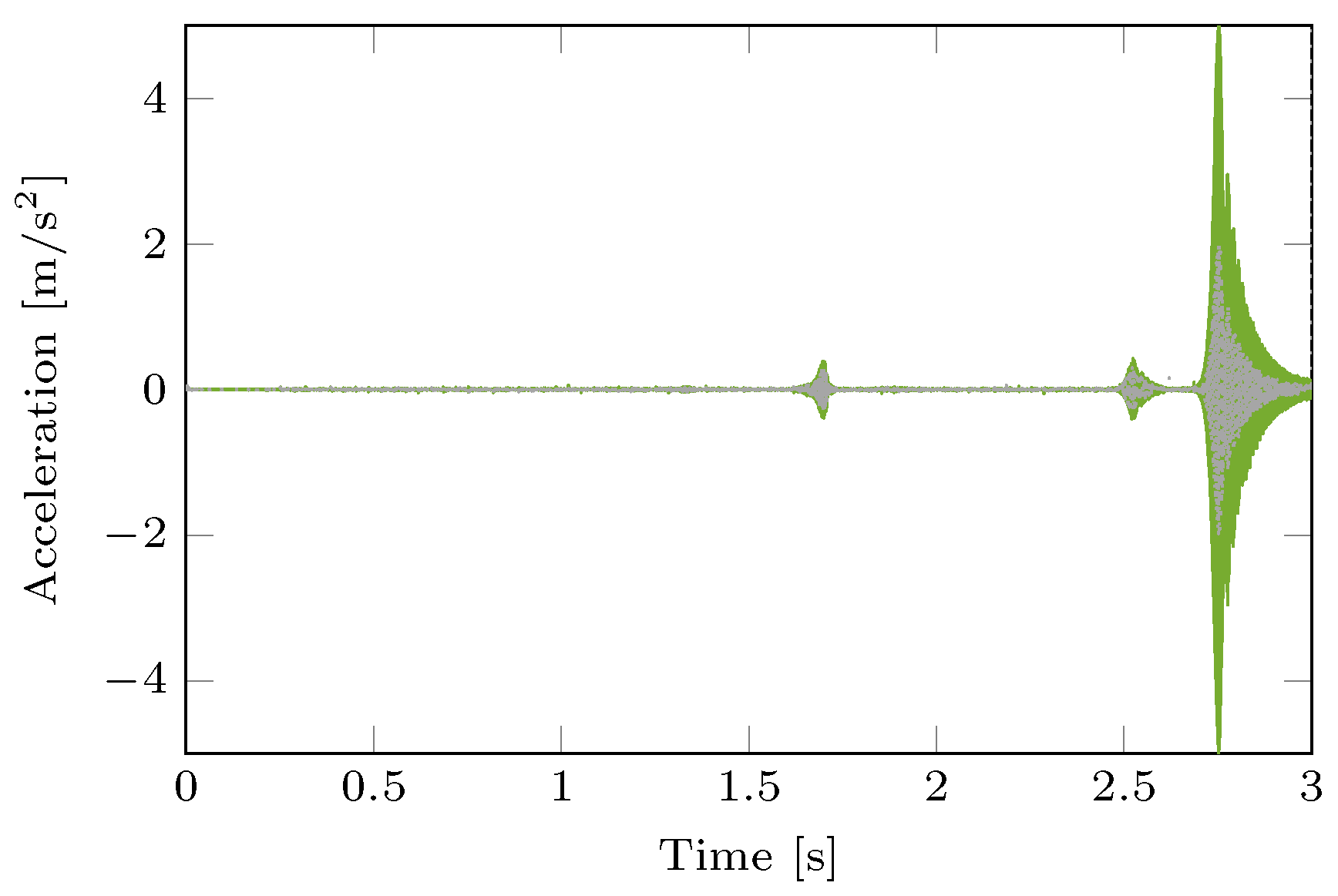
In this section, the results of transient simulation performed with the simplified contact assumption Subs-c are compared with the results of the reference method FiLm. This simplification can be considered when the static deformation does not significantly change the normal and tangential contact force direction. Figure 9 shows the vertical acceleration of the free end T of the horizontal beam evaluated using the two methods. Results show that, also in this simplified form, the contact assumption shows qualitatively good response and detects the presence of friction-induced instabilities. However, the amplitude of vibration bursts is overestimated because it is sensitive to the value of the normal contact force in Figure 10, which in this case does not decrease because of the simplified contact assumption. In fact, the simplified contact assumption does not consider the effect of the system deformation on the normal force direction (and amplitude). The computational time required to obtain the solution using the Subs-c method is 69% of the time required by the reference method.
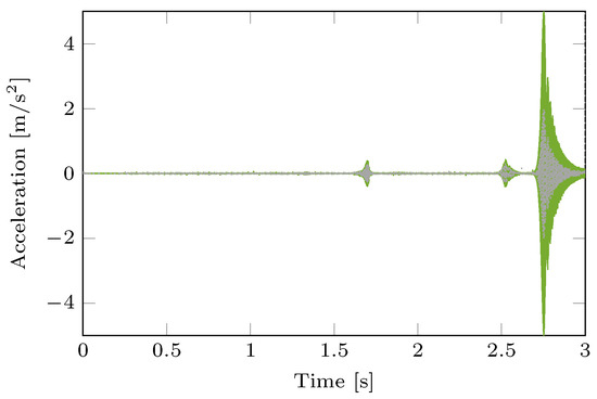
Figure 9.
Vertical acceleration of point T: comparison between  Subs-c and FiLm method.
Subs-c and FiLm method.
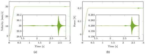
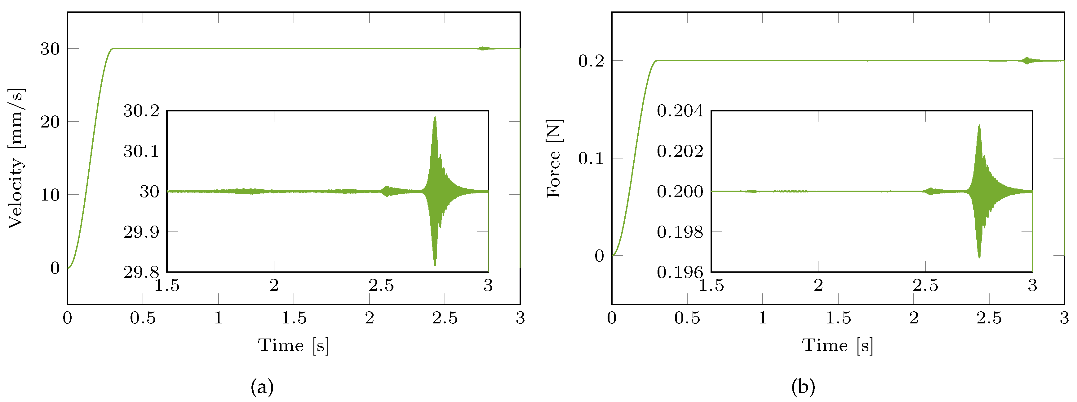
Figure 10.
Relative velocity (a) and normal contact force (b) for the Subs-c method.
4. Conclusions
In this paper, the transient response of a mechanical system, composed of two subsystems connected through a frictional contact interface, is evaluated using a substructuring method. Results are validated by comparing them to those provided by a reference numerical method [27]. Different contact assumptions made in the formulation of time-dependent compatibility and equilibrium conditions of the substructuring method are considered. The basic contact assumption is that the time-dependent compatibility and equilibrium conditions, deriving from sliding contact, are a-priori known. The comparison of the results with the reference method highlighted that this approach correctly estimates the effects of configuration changes due to relative sliding on the global dynamics of the system. However, it is not able to reproduce friction-induced vibrations since it does not properly account for the relative displacement at the contact interface due to the body deformation. The realistic contact assumption fully accounts for the deformation of the mechanical system in establishing the compatibility and equilibrium conditions. The comparison of the results with the reference method highlighted that this approach is able to retrace the system’s dynamic response, also in case of unstable friction-induced vibration due to mode coupling. A simplified approach, relying on a simplified contact assumption, is proposed in this paper. It accounts for the relative displacement at the contact interface due to the body deformation but disregards the direction change of the normal to the contact surface. The simplified approach provides a qualitatively good response, and it is equally able to detect the onset of friction-induced instabilities. The comparison of the computational time highlights a significant reduction of the computational burden of the three substructuring methods with respect to the reference method. In particular, using the realistic contact assumption, the computational time required is 26% lower than that required by the reference method. In turn, using the simplified contact assumption is about 7% faster than the realistic contact assumption.
The results show how the choice of the contact algorithm allows for tackling a wide range of operating conditions, from simple position-dependent problems up to complex friction-induced vibration problems, with a significant saving of computational time. Specifically, the approach proposed in this paper is able to detect the onset of friction-induced instabilities with the lowest computational effort.
Author Contributions
All authors have equally contributed to the conceptualization, methodology, and writing of this research. All authors have read and agreed to the published version of the manuscript.
Funding
This research is supported by Università degli Studi di Roma La Sapienza and Università degli Studi dell’Aquila.
Data Availability Statement
Not applicable.
Conflicts of Interest
The authors declare that they have no conflict of interest.
References
- Ibrahim, R.A. Friction-Induced Vibration, Chatter, Squeal, and Chaos—Part I: Mechanics of Contact and Friction. Appl. Mech. Rev. 1994, 47, 209–226. [Google Scholar] [CrossRef]
- Ibrahim, R.A. Friction-Induced Vibration, Chatter, Squeal, and Chaos—Part II: Dynamics and Modeling. Appl. Mech. Rev. 1994, 47, 227–253. [Google Scholar] [CrossRef]
- Akay, A. Acoustics of friction. J. Acoust. Soc. Am. 2002, 111, 1525–1548. [Google Scholar] [CrossRef] [PubMed]
- de Klerk, D.; Rixen, D.J.; Voormeeren, S. General Framework for Dynamic Substructuring: History, Review, and Classification of Techniques. AIAA J. 2008, 46, 1169–1181. [Google Scholar] [CrossRef]
- Sjövall, P.; Abrahamsson, T. Substructure system identification from coupled system test data. Mech. Syst. Sig. Process. 2008, 22, 15–33. [Google Scholar] [CrossRef]
- D’Ambrogio, W.; Fregolent, A. Inverse dynamic substructuring using direct hybrid assembly in the frequency domain. Mech. Syst. Sig. Process. 2014, 45, 360–377. [Google Scholar] [CrossRef]
- Mayes, R.L.; Ross, M.R. Advancements in hybrid dynamic models combining experimental and finite element substructures. Mech. Syst. Sig. Process. 2012, 31, 56–66. [Google Scholar] [CrossRef]
- Rixen, D. A dual Craig-Bampton method for dynamic substructuring. J. Comput. Appl. Math. 2004, 168, 383–391. [Google Scholar] [CrossRef]
- Brunetti, J.; D’Ambrogio, W.; Fregolent, A. Contact problems in the framework of dynamic substructuring. In Proceedings of the ISMA 2018—International Conference on Noise and Vibration Engineering and USD 2018—International Conference on Uncertainty in Structural Dynamics, Leuven, Belgium, 17–19 September 2018; pp. 3987–3998. [Google Scholar]
- Carassale, L.; Silvestri, P.; Lengu, R.; Mazzaron, P. Modeling Rail-Vehicle Coupled Dynamics by a Time-Varying Substructuring Scheme. In Proceedings of the Dynamic Substructures; Linderholt, A., Allen, M.S., Mayes, R.L., Rixen, D., Eds.; Springer International Publishing: Cham, Switzerland, 2020; Volume 4, pp. 167–171. [Google Scholar]
- Brunetti, J.; D’Ambrogio, W.; Fregolent, A. Dynamic coupling of substructures with sliding friction interfaces. Mech. Syst. Sig. Process. 2020, 141. [Google Scholar] [CrossRef]
- Voormeeren, S.N.; Rixen, D.J. A Family of Substructure Decoupling Techniques Based on a Dual Assembly Approach. Mech. Syst. Sig. Process. 2012, 27, 379–396. [Google Scholar] [CrossRef]
- Renouf, M.; Massi, F.; Saulot, A.; Fillot, N. Numerical Tribology of Dry Contact. Tribol. Int. 2011, 44, 834–844. [Google Scholar] [CrossRef] [Green Version]
- Sinou, J.J. Transient non-linear dynamic analysis of automotive disc brake squeal - On the need to consider both stability and non-linear analysis. Mech. Res. Commun. 2010, 37, 96–105. [Google Scholar] [CrossRef] [Green Version]
- Brunetti, J.; Massi, F.; Baillet, L.; D’Ambrogio, W. Application of the modal absorption index (MAI) to reduce the CEA instability over-prediction on a complex frictional system. In Proceedings of the ISMA 2016—International Conference on Noise and Vibration Engineering and USD2016—International Conference on Uncertainty in Structural Dynamics, Leuven, Belgium, 19–21 September 2016; pp. 3073–3083. [Google Scholar]
- Papangelo, A.; Putignano, C.; Hoffmann, N. Self-excited vibrations due to viscoelastic interactions. Mech. Syst. Sig. Process. 2020, 144, 106894. [Google Scholar] [CrossRef]
- Adams, G.G. Steady Sliding of Two Elastic Half-Spaces With Friction Reduction due to Interface Stick-Slip. J. Appl. Mech. 1998, 65, 470–475. [Google Scholar] [CrossRef]
- Tonazzi, D.; Massi, F.; Baillet, L.; Brunetti, J.; Berthier, Y. Interaction between contact behaviour and vibrational response for dry contact system. Mech. Syst. Signal Process. 2018, 110, 110–121. [Google Scholar] [CrossRef]
- Sinou, J.J.; Thouverez, F.; Jézéquel, L. Analysis of friction and instability by the centre manifold theory for a non-linear sprag-slip model. J. Sound Vib. 2003, 265, 527–559. [Google Scholar] [CrossRef] [Green Version]
- Hoffmann, N.; Gaul, L. A sufficient criterion for the onset of sprag-slip oscillations. Arch. Appl. Mech. 2004, 73, 650–660. [Google Scholar] [CrossRef]
- Wang, A.; Mo, J.; Wang, X.; Zhu, M.; Zhou, Z. Effect of surface roughness on friction-induced noise: Exploring the generation of squeal at sliding friction interface. Wear 2018, 402-403, 80–90. [Google Scholar] [CrossRef]
- Lazzari, A.; Tonazzi, D.; Massi, F. Squeal propensity characterization of brake lining materials through friction noise measurements. Mech. Syst. Sig. Process. 2019, 128, 216–228. [Google Scholar] [CrossRef]
- Wang, D.; Mo, J.; Wang, X.; Ouyang, H.; Zhou, Z. Experimental and numerical investigations of the piezoelectric energy harvesting via friction-induced vibration. Energy Convers. Manag. 2018, 171, 1134–1149. [Google Scholar] [CrossRef]
- Liu, J.; Wang, L.; Shi, Z. Dynamic modelling of the defect extension and appearance in a cylindrical roller bearing. Mech. Syst. Sig. Process. 2022, 173, 109040. [Google Scholar] [CrossRef]
- Brunetti, J.; D’Ambrogio, W.; Fregolent, A. Friction-induced vibrations in the framework of dynamic substructuring. Nonlinear Dyn. 2021, 103, 3301–3314. [Google Scholar] [CrossRef]
- Di Bartolomeo, M.; Lacerra, G.; Baillet, L.; Chatelet, E.; Massi, F. Parametrical experimental and numerical analysis on friction-induced vibrations by a simple frictional system. Tribol. Int. 2017, 112, 47–57. [Google Scholar] [CrossRef]
- Carpenter, N.J.; Taylor, R.L.; Katona, M.G. Lagrange constraints for transient finite element surface contact. Int. J. Numer. Methods Eng. 1991, 32, 103–128. [Google Scholar] [CrossRef] [Green Version]
- Newmark, N.M. A method of computation for structural dynamics. J. Eng. Mech. Div. 1959, 85, 67–94. [Google Scholar] [CrossRef]
- Brunetti, J.; Massi, F.; D’Ambrogio, W.; Baillet, L. Steady state of modal coupling instabilities as a dynamic energy equilibrium. In Proceedings of the ISMA 2014—International Conference on Noise and Vibration Engineering and USD 2014—International Conference on Uncertainty in Structural Dynamics, Leuven, Belgium, 15–17 September 2014; pp. 1827–1842. [Google Scholar]
Publisher’s Note: MDPI stays neutral with regard to jurisdictional claims in published maps and institutional affiliations. |
© 2022 by the authors. Licensee MDPI, Basel, Switzerland. This article is an open access article distributed under the terms and conditions of the Creative Commons Attribution (CC BY) license (https://creativecommons.org/licenses/by/4.0/).