1. Introduction
With the development of technology, electronic products play an important role in people’s lives. Within those products, the importance of the connector as a device power supply and the core link for device information transmission cannot be ignored. High-quality solder joints ensure that the connector works properly and stably, whereas defective joints can lead to hidden problems in terms of accuracy, safety, and stability [
1,
2,
3]. In the industry, the demand for cables is often insufficient to design a high-quality automatic welding machine specifically for the batch production of cables, so the main welding process of wire connectors is still manual. The task of detecting defects in solder joints of connector wires is currently performed primarily by manual inspection. Manual inspection relies on the human eye to observe the characteristics of the welding joints, then manual analysis is conducted empirically to check whether the welding joints meet the requirements of use so that the defective welding joints can be re-welded at any time to ensure that the product is used properly. However, intense workloads easily fatigue welders, which in turn reduces the quality of inspection and welding efficiency. In this case, designing an intelligent inspection method to automatically detect defective solder joints in connectors can significantly reduce the workload of engineers and improve the efficiency of manufacturing high-quality cables.
Theoretically, the use of image inspection can assist workers in analyzing welded joint defects and simplify the human visual inspection, thus improving the efficiency of detection and the quality of welding joints [
4,
5]. Traditional image detection algorithms can usually be divided into three parts: pre-processing, feature extraction, and recognition, among which the design of feature extraction and recognition is particularly important, and a large number of algorithms have been proposed by experts in related fields [
6,
7,
8,
9,
10], collectively known as automatic optical inspection (AOI). AOI is widely used for the detection of solder joint defects on the surface of printed circuit boards (PCBs), in which industrial cameras are used to obtain images and design different algorithms to complete the task of detecting defects in electronic products, leading to a significant improvement in detection. Wang et al. proposed a PCB solder joint detection method based on an automatic threshold segmentation algorithm and an image morphology feature extraction algorithm, which improved the efficiency and accuracy of PCB solder joint detection [
7]. Xiao et al. proposed an image acquisition path planning method and solution algorithm for PCB surface defect detection, introduced a negative feedback mechanism to address the problem of the ant colony not being able to get rid of the local optimal solution, and used a position adjustment method to solve the uncertainty of the local position of the image acquisition window, which shortened the path length without changing the time complexity [
9]. Fang used Haar-like features and the AdaBoost classifier to detect three defects of multi-angle polarity capacitors and verified the effectiveness of the algorithm through experiments [
10]. However, AOI usually requires specific algorithms designed according to the target, which is less universal and the complexity of the algorithm is higher in some scenarios, so it is not very widely used in industrial applications.
With the introduction of machine learning concepts [
11], theories such as deep learning [
12,
13,
14,
15,
16,
17,
18,
19,
20,
21,
22,
23,
24,
25,
26], transfer learning [
27], reinforcement learning [
28], and federation learning [
29,
30] have emerged and been applied to many domains, such as natural language processing [
31], weather prediction [
32], behavior prediction [
33], fault diagnosis [
34], and target detection [
35,
36]. Among these theories, deep learning, as a subclass of machine learning, has received extensive attention in defect detection tasks, and various defect detection algorithms based on deep neural networks have performed exceptionally well [
13,
14,
15,
16,
17,
18,
19,
37,
38,
39,
40]. Li et al. improved the YOLOv3 algorithm by adding a shallow layer and using the feature map of PCB components extracted from this layer for detection, thus overcoming the small-target detection difficulties. The dataset was also expanded using data federation and data augmentation, which improved the mAP of the network by 16% [
17]. Tommaso et al. improved the YOLOv3 target detection network and proposed a YOLOv3-based multi-stage model for detecting panel defects in aerial images acquired by UAVs and predicting the soil coverage area [
38]. The model has high generality and is capable of handling thermal or visible images, and the detection accuracy AP@0.5 for panel defects can reach 98%. Zhao et al. proposed a lightweight convolutional neural network to achieve online defect detection on the inner surface of micro tubes [
39]. The network uses a shallow segmentation network with a lightweight convolutional neural network for pixel-level crack detection, and its accuracy of defect detection reaches 98.5%, with the product of the average intersection of the segmentation and the concatenation set being 0.834. Zhang et al. proposed a cost-sensitive residual convolutional neural network [
40]. The network adds a cost-sensitive adjustment layer to the standard ResNet and assigns a larger weight to a few real defects in the PCB dataset according to the class imbalance. In addition, in the design of the loss function of the network, Zhang et al. proposed optimizing the cost-sensitive residual convolutional neural network by minimizing the weighted cross-entropy loss function. Experiments show that the network can solve the problem of unbalanced class distribution of real and pseudo-defects on the PCB surface. Deep neural network-based target detection algorithms usually use convolution and pooling layers to complete feature extraction and use fully connected layers to classify the extracted features, so that no special algorithms are needed to be designed for different scenarios. Moreover, the use of weight sharing in the feature extraction stage greatly reduces the training difficulty and cost. Therefore, compared with traditional target detection algorithms, deep neural networks can solve more complex target detection tasks, and the algorithm process is simple and straightforward, which can greatly improve the detection accuracy.
Despite the fact that defect detection based on deep neural networks has been extensively explored and many related detection methods have been proposed, the detection of defects in connector solder joints is very rare. The main reasons for this situation are related to the following aspects:
There are differences in the internal design of different electronic devices, and therefore the type of connector varies greatly. Different connectors have different pin layouts and solder joint locations, and the angles of the solder joint images can vary, making it difficult to design feature extraction algorithms that are adaptable to multiple scenarios.
Soldering of cables and connectors is different from PCB and is usually done by manual soldering. Manual welding is inevitably subject to large welding errors, such as the temperature of the soldering gun, welding time, the amount of solder used. The uncertainty of manual welding leads to a variety of manifestations of connector solder joints, and the same category of solder defects may also show different forms and textures. Therefore, it is difficult to design feature extraction algorithms and classification algorithms to effectively differentiate between solder defects.
At present, the manufacturing of small numbers of cables is still done by engineers. They have to complete the welding and manual detection of solder joint defects at the same time, and this manufacturing process hinders the development of automatic defect detection systems. It is believed that engineers can detect solder joint defects in real time during the soldering process and re-weld the defective solder joints. However, in practice, certain solder joint defects require careful observation by experienced engineers, which tends to cause engineer fatigue, leading to them overlooking certain imperceptible defects in the solder joints, which thus reduces the lifetime of the devices.
Therefore, research on intelligent detection methods for connector solder joint defects is essential. Given that deep neural networks are capable of performing defect detection tasks in various industries with their unique advantages, we believe that deep neural networks will continue to perform well in connector solder joint defect detection tasks. In our previous work [
19], an improved Faster-RCNN algorithm was used to do detection on five types of solder joints with a mAP of 0.941 and a top-1 detection accuracy of 94%. The experimental results strongly demonstrate the feasibility of using deep neural networks for the connector solder joint defect detection task. However, as the first dataset of connector solder joints was simulated by us for research purposes, we did not have as high soldering skills as professional engineers, so the samples were relatively simple. For the latest dataset, we invited a professional soldering engineer to complete the soldering of the connector and the core wire. A total of eight types of solder joints were realized, and the solder joint conditions were more in line with production reality. When experimenting with the latest dataset, we found that all the metrics were significantly lower. The latest connector solder joint samples were analyzed and it was found that in the new dataset there were more connector pins, larger connector sizes, and correspondingly smaller solder joints in the image in terms of proportion and number of pixels. In other words, in the latest connector solder joints dataset, as the number of solder joints becomes larger but the scale becomes smaller, the features of the solder joints become somewhat blurred. Our previous work only used the feature maps that were down-sampled from the original image with a factor of 32 for the extraction and classification of the proposals, which is less effective for detecting small-scale, blurred solder joints.
To solve the above problems, an effective multi-scale feature network is proposed in this paper. The network uses the fusion of adjacent-stage feature maps to generate feature pyramids and introduces a feature enhancement module to further enhance the fused feature maps. Experimental results show that the network can effectively detect eight types of connector solder joints with higher detection accuracy than other mainstream target detection frameworks and has better detection for small-scale and blurred solder joint defects.
The sections in this paper are organized as follows:
Section 2 details the overall structure of the proposed multi-scale feature network, the highlight design in the network, the loss function used in the network, and the specifics of the dataset used in the experiments.
Section 3 shows the experimental results related to the ablation experiment and the comparison experiment and provides a detailed analysis of the experimental results.
Section 4 discusses the experimental results from a macro perspective and points out the focus of future work.
Section 5 summarizes the research content of this paper.
The contributions of this paper are as follows:
There has been little research on the detection of defective solder joints in connectors. In this paper, a network that can effectively detect defective solder joints in connectors is proposed, which uses feature fusion and feature enhancement to extract multi-scale feature maps and improve the detection accuracy of defective solder joints in connectors.
In this paper, a higher-stage feature map up-sampling algorithm is presented, which can be applied to deep neural networks that need to fuse feature maps of different scales to improve the expressiveness of the fused feature maps. In addition, the feature enhancement module used in this paper can further enhance the expressiveness of the fused feature maps, thus improving the overall detection accuracy of the network.
This paper provides a detailed analysis of the causes, manifestations, and pitfalls of different connector solder joint defects and provides a basis for analyzing the quality of solder joints when welding connectors in industry.
There is no open source dataset for connector defective solder joints. The dataset used in this paper will be made available to other scholars who are interested in connector defective solder joint detection.
2. Materials and Methods
2.1. Network Architecture
In this paper, the details of feature pyramid network (FPN) [
20] are improved by introducing a learnable feature map up-sampling algorithm as well as a feature enhancement module to fuse multi-level feature maps to enrich and highlight features. The structure of the proposed network is shown in
Figure 1.
The multi-scale feature network proposed can be divided into four modules from an overall perspective, namely the feature map sets generation module, the feature enhancement module, the region proposal generation module, and the classification and regression module.
The feature map sets generation module is designed with three branches, in which the bottom-to-up branch uses ResNet-101 to extract multi-scale feature maps [C1, C2, C3, C4, C5] with scales corresponding to [1/2, 1/4, 1/8, 1/16, 1/32] compared to the original image. In all laterally connected branches, except the top branch, 1 × 1 convolution is used to limit the number of corresponding feature map channels to 256 in order to facilitate the fusion of feature maps in adjacent stages. In the top branch, in addition to 1 × 1 convolution, the highest stage feature map is further down-sampled using the maximum pooling operation to obtain the virtual higher stage feature map P6. The two are superimposed and further modified by 3 × 3 convolution to complete the fusion of adjacent order feature maps. In this way, the feature map generation module finally generates a pyramid-like feature map set [P2, P3, P4, P5, P6]. As P6 is simply designed for the fusion of P5 with a down-sampling ratio of 1/64, which cannot characterize the target features well, we discard P6 and only use [P2, P3, P4, P5] as the feature map set to participate in the subsequent process.
The feature enhancement module introduces learnable parameters from both spatial and channel directions to enhance the feature sets [P2, P3, P4, P5] so that the noise generated by different stages of feature fusion is weakened and the useful feature information is emphasized, resulting in a feature map set [F2, F3, F4, F5] with stronger feature representation capability.
The region proposal generation module uses the region proposal network (RPN) to generate proposals. Nine anchors are generated for each pixel position of the feature map at each stage of the feature map group [F2, F3, F4, F5], and the RPN corrects the anchors and maps them to the input image according to the reduced ratio of the feature map at each stage. The non-maximum suppression (NMS) algorithm is used to remove redundant proposals from all generated original proposals, and the intersection of union (IOU) between proposals and labeled boxes is used to determine whether the proposals belong to the foreground or background. In other words, RPN generates proposals at each stage of the feature map for the feature map group [F2, F3, F4, F5] and adds labels to them.
The classification and regression module uses two fully connected layer branches to calculate the category scores and location regression parameters of the proposals, respectively. As generated proposals are of variable size, the fully-connected layer requires the input to be a vector of fixed size. Therefore, RoI Align is used to reset the size of the proposals to 7 × 7 and subsequently calculate the category score and location regression parameters.
The feature extraction module uses ResNet-101 as the base network. The bottom-up branch generates multi-stage feature maps set [C1, C2, C3, C4, C5] from the input image, the highest-stage feature map C5 generates P6 after the max-pooling layer, and then the top-down branch fuses the current feature maps with the lower-stage feature maps in the adjacent bottom-up branches to generate a new feature map. The lateral connection branch serves to limit the number of feature map channels and allows for easy fusion of feature maps at adjacent levels. The approach borrows from the generated way of FPN feature map sets to obtain [P2, P3, P4, P5, P6]. For the purpose of highlighting the useful features, a feature enhance module is introduced to further modify the generated feature map sets, and finally the feature map sets [F2, F3, F4, F5] are yielded.
The pseudo-code of the training process of the proposed multi-scale feature network in this paper are shown in Algorithm 1.
| Algorithm 1 Training process pseudo-code of multi-scale feature network. |
# Label boxes:
# Label category:
# Input:
# Max epochs:
Initialize network parameters and load ResNet-101 pre-trained model |
| For in : |
| Extract multi-scale feature map set |
|
|
| For in range : Get feature map set |
|
|
|
|
|
|
|
|
| Set anchors on , get initial proposals |
| Mapping to , get |
|
|
|
|
| Select 128 foreground proposals and 128 background proposals |
|
|
|
|
|
|
|
|
| Update network parameters by backpropagation |
2.2. Content-Aware Feature Up-Sampling (CAFUS)
Because neighboring feature maps have different scale levels and cannot be fused, the introduction of up-sampling to amplify higher-level feature maps is a very important part of the network. Feature map up-sampling is an essential image amplification technique, and we aim to retain the maximum amount of semantic information contained in the higher-level feature maps after up-sampling, without introducing too much noise and computational effort. Image up-sampling techniques include interpolation [
41] (nearest neighbor interpolation, bilinear interpolation, bicubic interpolation), deconvolution [
42], and dynamic filters [
26]. The interpolation method computes new pixels only by pixel positions, which does not take advantage of the semantic information of the image, and the perceptual field and computation cost cannot be balanced. For example, the nearest-neighbor interpolation and bilinear interpolation methods are relatively small in computation, but the perceptual fields are only 1 × 1 and 2 × 2, whereas the perceptual field of bicubic interpolation can reach 3 × 3, despite its large computation cost. In addition, the up-sampled images obtained by the interpolation method usually have local distortion, and the noise introduced affects the learning effect of the network for features. The deconvolution method can improve the above problems to some extent by learning the kernel parameters through convolutional networks without considering the pixel positions. However, this method does not consider local semantics and uses the same convolutional kernel for each local region, which still cannot effectively restore local feature information. Moreover, when the convolution kernel is designed to be too large, the computational effort grows exponentially. The dynamic filtering method designs a convolutional kernel for each position of the image, and, as one can imagine, the number of parameters introduced by this method is too large for practical applications.
Content-aware reassembly of features (CARAFE) [
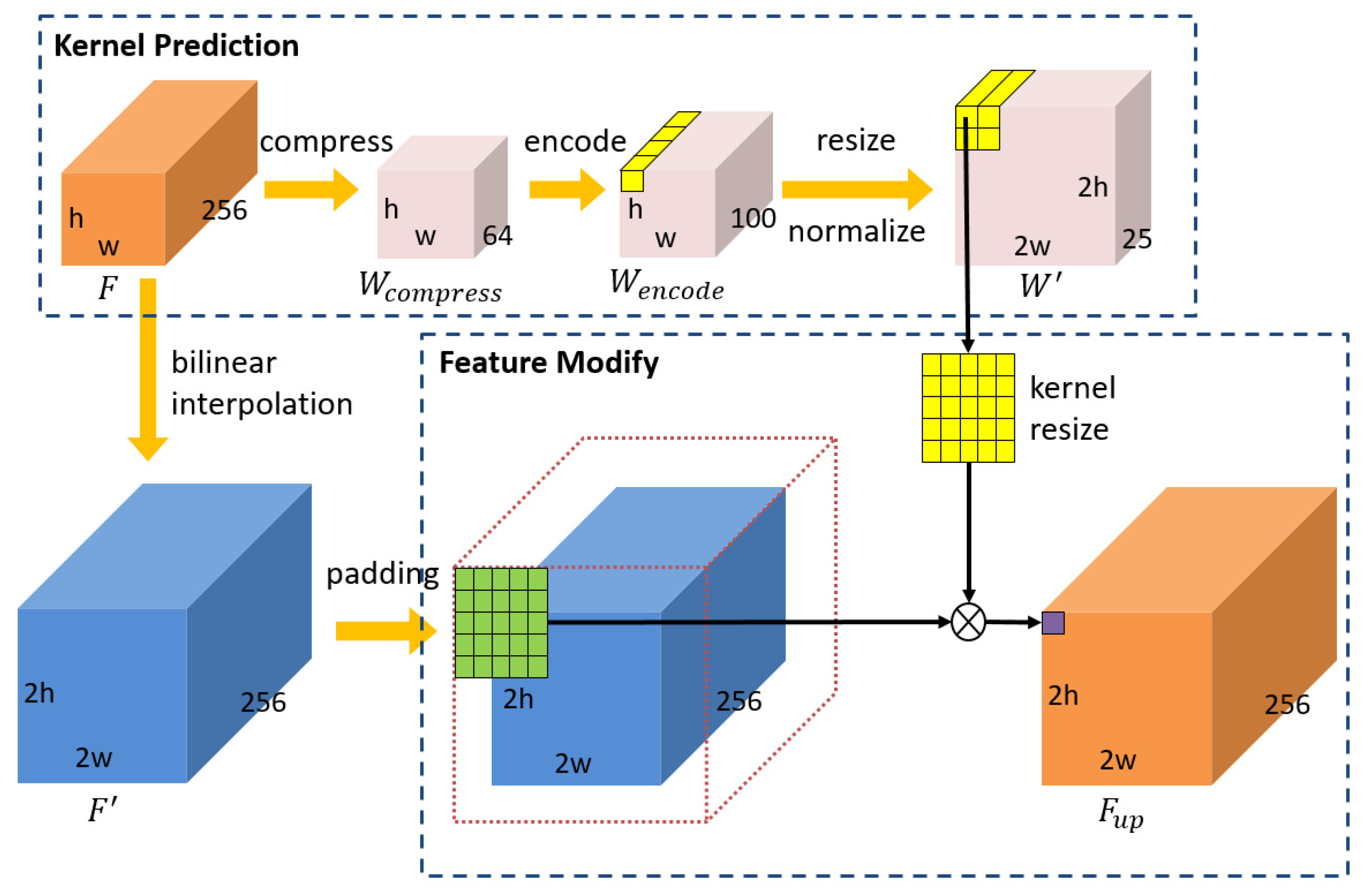
43] is a learnable image up-sampling algorithm based on the input content, which divides the feature map up-sampling into two parts, i.e., up-sampling kernel prediction and feature reassembly. Experiments show that CARAFE has a large perceptual field; the model is sufficiently light enough to retain the feature information of the input better. More importantly, CARAFE will enhance the feature semantics to some extent. The proposed feature map up-sampling method, named content-aware feature up-sampling, improves the CARAFE algorithm, as shown in
Figure 2. CAFUS modifies the bilinear interpolated image by predicting the up-sampling kernel parameters based on the input feature map, which makes up for the disadvantages of the interpolation method without introducing too many parameters that would result in excessive training cost.
CAFUS up-samples the input feature map
using bilinear interpolation to obtain the up-sampled feature map
, where
denotes the up-sampling ratio and
denotes the dimensionality of the input feature map. The
neighbourhood of the feature map
at position
is defined as
for easier understanding. Subsequently, the up-sampling modification kernel prediction module predicts the up-sampling modification kernel parameters based on the elements at each position
of the input feature map, as shown in Equations (1)–(4). The whole process is mainly implemented by two convolutional layers: the first convolution layer uses a 3 × 3 convolution kernel to compress the number of channels in the feature map to 64, and the second convolution layer uses a 3 × 3 convolution kernel to expand the number of channels in the feature map to
, where
represents the scale of the neighborhoods involved in the calculation when the features are modified, and get
. The dimension of
to
is resized, and the elements at each position
is normalized, with the resulted
containing all the up-sampling modification kernels. Finally, the elements at each position in
are convolved with the
neighborhoods at the corresponding position in
to finalise the modification of the upsampled image after bilinear interpolation, as shown in Equation (5).
In this paper, , .
2.3. Feature Enhancement Module (FEM)
During the generation of the feature map, as the number of convolution layers increases, the content of the extracted feature expressions deepens layer by layer. In other words, shallow convolution extracts low-level feature representations, such as points, lines, and curves, whereas deep convolution extracts high-level feature representations, such as contours, textures, and chromatic differences. Although the feature extraction module used in this paper uses a
convolution to correct the fused feature maps when fusing the feature maps of adjacent stages, conflicting representations are inevitable due to the large span of feature levels represented by the five stage feature maps extracted by ResNet-101. In this case, the fused feature maps do not fully contain both low-stage semantic information and high-stage semantic information, but instead lead to weakened feature representation. In order to solve this problem, this paper proposes a feature weighting algorithm to further enhance the feature information, i.e., the feature enhance module. The algorithm principle of the feature enhance module is shown in
Figure 3. The feature enhancement module assigns weights to the feature maps from two directions, thus enhancing the useful features.
In the spatial direction, the fused feature map contains both target features and background information. The feature map is modified along the two-dimensional spatial direction to enhance the target features. The specific weight parameters are calculated as shown in Equations (6) and (7). In Equation (7),
represents the multiplication of elements in the corresponding position.
In the channel direction, as each level of the feature map group contains 256 channels, not every channel of the two-dimensional feature map can contain the target feature information well. Therefore, feature map channel weights are introduced to assign a coefficient to each channel, so that the feature maps containing the target features in the feature map sets can be used to greater effect. The feature map channel weight parameters are calculated as shown in Equations (8)–(10). In Equation (4),
represents a sigmoid function and
represents an ReLU activation function.
Finally, the features modified in both directions are fused together, as shown in Equation (11), and the fused feature map will contain stronger feature information.
2.4. Loss Function
The training of a deep neural network refers to the iterative optimization of the network parameters, where the key lies in the design of a reasonable function to calculate the network prediction error, i.e., the loss function. In the process of supervised learning, samples and labels are passed into the network at the same time, and the network predicts the results and participates in the calculation of the loss together with the input labels, subsequently updating the parameters layer by layer according to the magnitude of the loss in reverse, and finally obtaining a refined model. Image target detection requires not only determining the category of the target, but also finding the location of the target, so the total loss is mainly composed of two parts: category loss and location loss. The proposed network uses both cross-entropy and smooth-L1 to calculate the loss. Cross-entropy can accurately calculate the category loss of multi-category targets while adaptively controlling the update of parameters during back-propagation according to the loss size to avoid over-fitting of network parameters. The smooth-L1 curve is smooth, the derivatives do not change abruptly, and it has good robustness to outliers. The network proposed in this paper is two-stage, and the losses of the main network and the region proposed network need to be calculated separately, as shown in Equations (12)–(16).
where
represents the number of images in one mini-batch at training,
represents the number of anchors generated in each image, and
represents the balance factor. The value
refers to the category score vector of the proposal box,
represents the label of the proposal box,
represents the position parameter of the proposal box, and
represents the position parameter of the ground truth box.
where
represents the category score predicted by the network,
represents the score of the ground truth,
represents the coordinate of the ground truth, and
represents coordinate of the predicted box.
2.5. Description of Connector Solder Joint Dataset
Connector solder joints have many types of defects, and defective joints will affect the accuracy, safety, and stability of the connector during use. We use multi-level feature fusion and feature enhancement to complete the task of detecting qualified solder joints and seven types of defective solder joints; the details of the solder joints to be detected can be seen in
Table 1 and
Figure 4.
3. Results
Currently, there is very little research on connector solder joint defect detection. Therefore, a common deep convolutional neural network-based image target detection network was chosen to compare with the multi-scale feature network proposed in this paper. Additionally, in order to verify the effectiveness of the feature map up-sampling algorithm CAFUS and the feature enhancement module FEM, corresponding ablation experiments were conducted. In terms of hardware, all experiments in this paper use NVidia GTX1050Ti 8G GPU and Inter Core I7-8750h CPU. In terms of software, due to the different libraries used by the open source framework, Faster-RCNN [
21], SSD [
25], and our previous work [
19] were implemented using Tensorflow, whereas YOLO [
22], FPN [
20], and the proposed multi-scale feature network were implemented using Pytorch. In all experiments, simple names were used to indicate the types of connector solder joint. Where “hg” denotes qualified solder joints, “dx” represents multi-solder joints, “sx” denotes less-solder joints, “xj” denotes tip-solder joints, “lh” refers to connected-solder joints, “cc” denotes rough-solder joints, “lx” denotes bare wire joints, and “wx” denotes skewed wire joints.
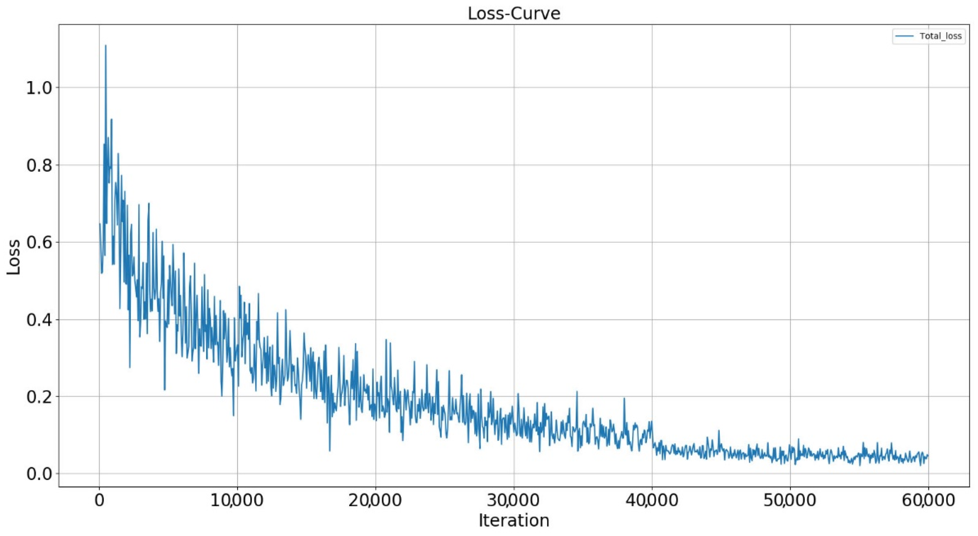
Figure 5 shows the variation of the total loss of the network during the training process of multi-scale feature network. The number of iterations was set as 60,000 and the total loss of the network was recorded every 100 iterations, and the recorded results were plotted as curves. It is not difficult to find that at the beginning of the network training, the losses are larger and the magnitude of the loss oscillation is obvious. As the network parameters are progressively optimized, the training loss decreases. After 10,000 steps of training, the loss decreases less and after 40,000 steps of training, the loss stabilizes at around 0.05. It can be seen that the multi-scale feature network optimizes the network parameters well during the training process, the final total loss is very low, and the network accuracy is high.
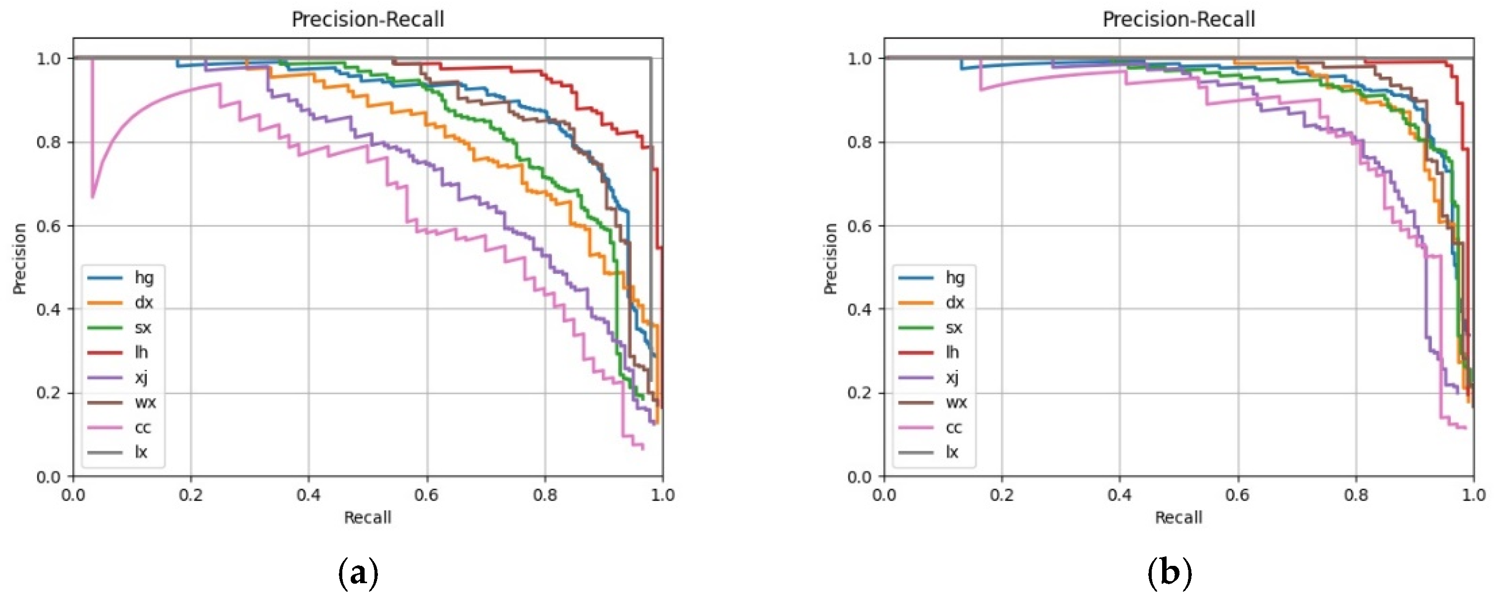
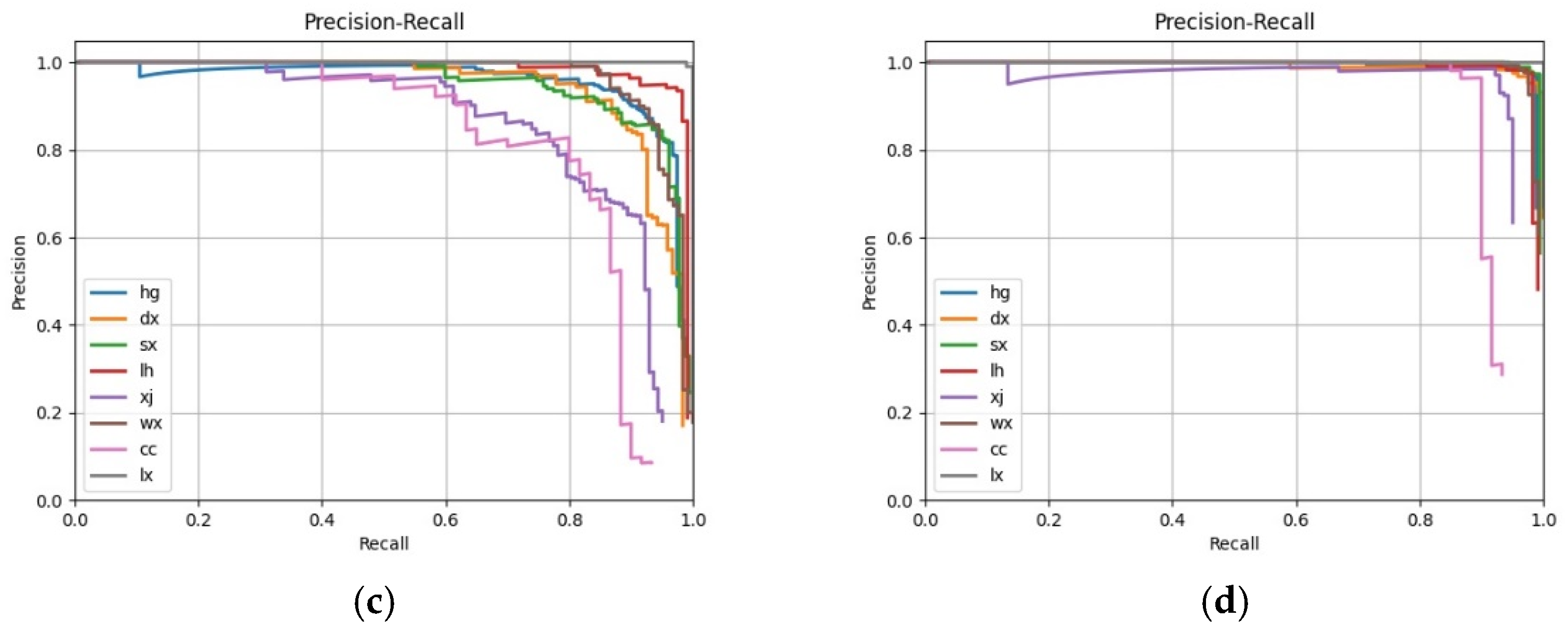
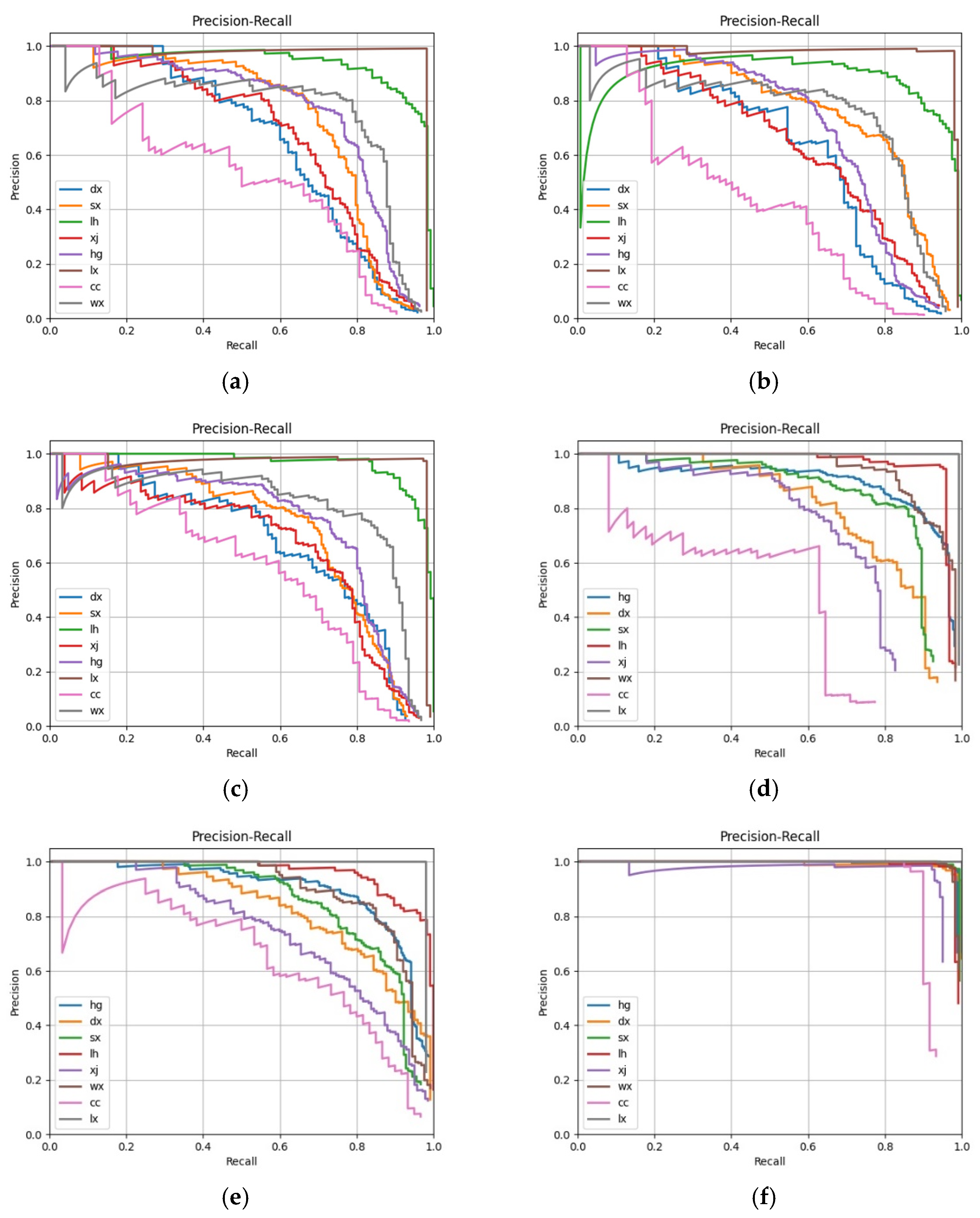
In a multi-classification target detection task, each category can be plotted on a curve, known as a P-R curve, based on recall and accuracy. The average precision (AP) is the area under that curve, and the mean average precision (mAP) is the average value of the APs for each category. The mAP is one of the important indicators of how good a deep learning model is, and its value ranges between 0 and 1: the higher the value, the better the model. To verify the effectiveness of CAFUS and FEM in improving the detection capability of the network, corresponding ablation experiments were conducted to train FPN, FPN with CAFUS, FPN with FEM, and the proposed multi-scale feature network. The experimental results are presented in
Figure 6 and
Table 2. Comparing the experimental results, it was found that a 5.4% increase in the mAP of the network from 0.817 to 0.871 could be achieved using CAFUS, compared to the FPN using bilinear interpolation for feature map up-sampling. Correspondingly, the introduction of FEM increases the mAP of the network by 0.862. A mAP of 0.929 was achieved when using both CAFUS and FEM for the multi-scale feature network, an increase of 11.2% compared to FPN. This shows that the use of CAFUS can guarantee the up-sampling quality of the high-level feature maps during the multi-scale feature map fusion. Additionally, FEM has a better enhancement effect on the feature representation ability of the feature map.
In order to better demonstrate the advantages of the multi-scale feature network in the detection task of connector solder joint defect, several commonly used detection frameworks that are well recognized in the field of image target detection, namely Faster-RCNN, YOLO, SSD, and FPN, were chosen for comparison of detection results. In our previous work, an improved Faster-RCNN was also added to the comparison experiments.
Figure 7 shows the P-R curves of the different frameworks. The APs for each connector solder joint and mAPs of the different frameworks are recorded in
Table 3, and the top-1 detection accuracy of the connector solder joints in 92 test images for the different frameworks are recorded in
Table 4. The experimental results show that the multi-scale feature network significantly outperforms other frameworks in a number of metrics, with the network achieving a mAP of 0.929, which is improved by 20.3%, 23.1%, 18.7%, 14.3%, and 11.2%, respectively, compared to the other networks. Also, in terms of actual detection accuracy, the multi-scale feature network is able to detect connector solder joint defects better than other frameworks, with a higher top-1 detection accuracy of 92% on average than the other frameworks.
Table 5 lists the test time per image for the target detection frameworks involved in the experiments. Being a two-stage framework, its detection time consumption is higher compared to the one-stage framework, but the introduction of CAFUS and FEM does not make the network more complex compared to FPN, and the detection times are almost identical.
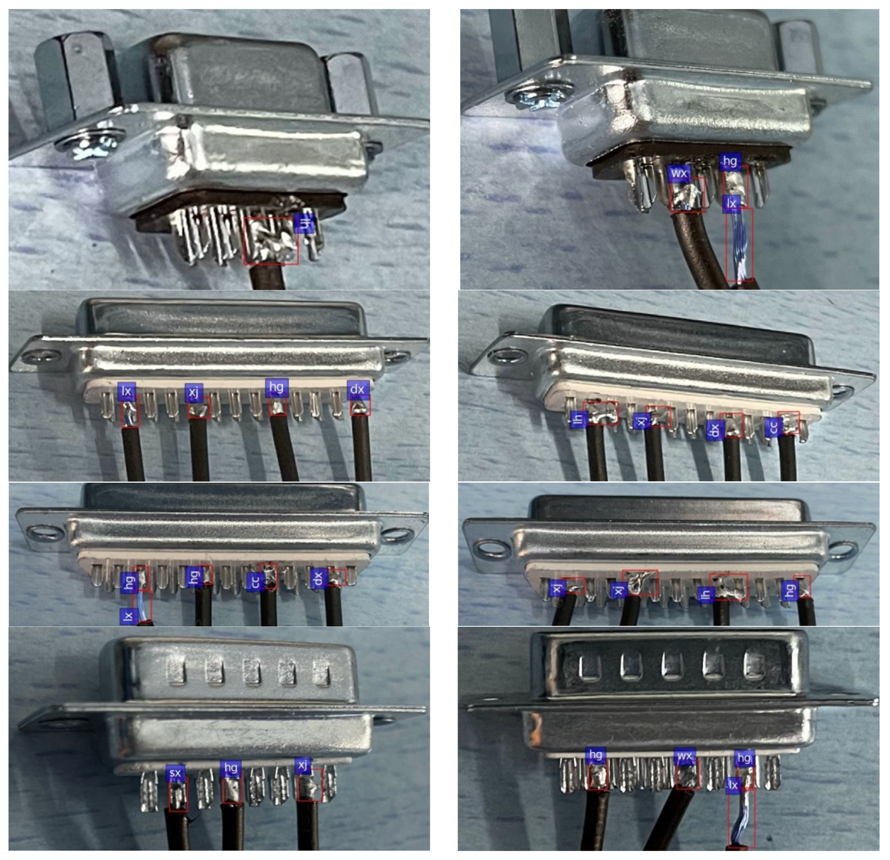
Some results of the connector solder joint detection framework proposed in this paper are shown in
Figure 8.
4. Discussion
In this paper, the FPN was optimized and a more efficient multi-level feature fusion and feature enhancement network was proposed to solve the connector solder joint defect detection problem. In our latest dataset, many types of solder joints contain a small number of pixels and the detection of solder joints is converted to a small target detection problem. Additionally, as most connectors are soldered manually, multiple uncertainties lead to insignificant inter-class differences in connector solder joints, making the detection of connector solder joints difficult. The experimental results in
Table 4 show that the proposed framework using top-level feature maps for extraction and classification is grossly inadequate for detecting a variety of small-scale solder joint defects, such as multi-solder, less-solder, tip-solder, rough-solder, and skewed wire, whereas it is better for detecting other large-scale solder joint defects. The main reason for this phenomenon is that the down-sampling ratio of highest-level feature map is too large compared to the input image, so the feature representation capability of the highest-level feature map is weak and the network cannot optimize the parameters based on the existing feature information. Multi-scale feature fusion can fuse high-level features and low-level features, which reduces the difficulty of self-learning of the detection network, and therefore greatly improves the detection capability of small-scale targets while ensuring that the accuracy of detection of large-scale targets is not degraded.
The multi-level feature fusion and feature enhancement network proposed in this paper uses content-aware feature up-sampling instead of bilinear interpolation to complete the up-sampling of the high-level feature maps, and it introduces the feature enhancement module to further highlight the useful features. To verify the effectiveness of CAFUS and FEM, relevant ablation experiments were performed, and the experimental results are presented in
Table 2. The experimental results show that the accuracy of the network is greatly improved by using both CAFUS and FEM. It can be demonstrated that CAFUS can retain the feature information of the high-level feature maps after sampling to a greater extent, and the enhancement effect of FEM on the feature information is also obvious.
As shown in
Table 5, the detection time of the multi-level feature fusion and feature enhancement network proposed in this paper is 0.47 s, which means that two images can be detected per second. This result indicates that although the framework proposed in this paper has advantages in detection capability, it cannot meet the requirement of real-time detection. The main reason for this result is that the structure of the network proposed in this paper is relatively complex, so simplifying the network will be the focus of our work in the future.
5. Conclusions
In this paper, a multi-level feature fusion and feature enhancement network is proposed to solve the connector solder joint detection problem, which achieves the detection and localization of eight solder joint types, resulting in a large improvement in model accuracy and detection accuracy compared to other mainstream frameworks and our previous work. In addition, content-aware feature up-sampling was employed in the network to up-sample the high-level feature maps, and a feature enhancement module was used to further enhance the feature representation of the fused feature maps. Experiments show that CAFUS and FEM improve the effect of the network significantly.
Nevertheless, there is still much room for improvement regarding the research in this paper. First, the network proposed in this paper only achieves high accuracy detection in eight types of common connector solder joints, and the detection effect for other defects still needs to be studied. Second, the network in this paper is relatively complex, which greatly increases the detection time of the network for each image and cannot meet the requirements of real-time detection. Therefore, in future work, the detection of connector solder joints will be further improved by analyzing more types of connector solder joint defects and using more novel algorithms. At the same time, we will introduce ideas such as federated learning to improve network training methods and enhance the effectiveness of the network. Finally, we will also focus more on the complexity of the network to make it meet the requirements of real-time detection.

