Abstract
Digital hydraulic technology as an emergent and important branch of fluid power offers good prospects for intelligence, integration, and energy saving of hydraulic systems. The high-speed on-off valve (HSV) that is a critical component of digital hydraulics has the drawbacks of specific design, narrow scope of application and high price compared to the commercial solenoid screw-in cartridge valve (SCV) widely used in the hydraulic industry at present. In this paper, a hybrid voltage control strategy composed of the preloading voltage, positive pulse voltage, holding voltage and negative pulse voltage is proposed to enhance the dynamic characteristics of the SCV, which makes it meet the demands of the digital hydraulics and achieve the end of replacing the HSV. Based on the structural analysis of the SCV, a mathematical model of the SCV is deduced. Subsequently, the simulation model of the SCV is developed in AMESim and validated by experimental measurements. The effects of the different duty ratios of the preloading voltage and holding voltage on the dynamic characteristics of SCV are studied, and the dynamic responses of the SCV under the normal voltage, positive and negative pulse and hybrid voltage control strategies are compared. The simulation results indicate that the increment of the preload voltage duty ratio and the reduction of the holding voltage duty ratio are conducive for decreasing the total opening and closing time of the SCV, especially the opening delay and closing delay time. The hybrid voltage control proposed has a better effect in dynamic characteristics than the other two strategies, using which the total opening time of the SCV reduces by 74.24% (from 29.5 ms to 7.60 ms), and the total closing time is drastically squeezed by 92.06% (from 136 ms to 10.8 ms). This provides a technical reference for improving the dynamic response speed of SCVs and popularizing digital hydraulic technology.
1. Introduction
The conventional electro-hydraulic proportional/servo system (EHPSS) has been widely used in robotics, aerospace, and precision machining, etc., because of its advantages such as high power mass rate and favorable dynamic performance [1]. The proportional/servo control valve, as a key control element of EHPSS, has the disadvantages of a complex structure, high power losses, contamination sensitivity and high price [2]. With the aggravation of the energy crisis and environmental pollution, the digital hydraulic technology based on high-speed switch valve is considered as a competitive alternative to EHSS by utilizing the advantages of its simple structure, fast response, anti-pollution ability, and good stability [3]. The opening and closing times are the most important index to evaluate the dynamic performance of the HSV in the digital hydraulic field, which directly affects the performance of a digital hydraulic system. Therefore, improving the dynamic performance of the HSV has become a research hotspot.
The HSVs have been studied much during the last decade. Most of the existing relevant research has improved the dynamic response characteristics by optimizing the structure and parameters of HSV. For example, in reference [4], the effects of the structural parameters (the valve spool diameter and the conical seat angle) on the linear control performance of HSV were researched by the method of computational fluid dynamics (CFD). In reference [5], based on energy losses of a mass-spring-damper system (MKsB), the armature mass importance on the HSV performance was investigated. In references [6,7,8], a cone valve type of HSV with a hollow spool structure was developed to realize a fast response. In references [9,10,11], a 2D valve whose spool had two degrees of freedom (rotary and sliding) and utilized the hydraulic fluid flowing through it as a power source for rotation, was designed to realize a fast response of HSV. In reference [12], a new scheme of parallel coils was investigated, in which the single coil of solenoid was replaced by parallel coils with the same ampere turns. In reference [13], the structure of the magnetic circuit, which employed newly developed Al–Fe soft magnetic materials, was redesigned to achieve a rapid response and strong magnetic force. In addition, a slice of special electromechanical conversion materials are used in HSVs. In references [14,15,16], the giant magnetostrictive and piezoelectric materials (GMM) were used as the electromechanical transducer of the HSV, which achieves a faster response. In order to further optimize the performance of the HSV proposed above, in references [17,18], a giant magnetostrictive valve (GMV) with an internal cooling structure and a novel high-speed jet dispenser driven with a double piezoelectric actuator were proposed. Meanwhile, intelligent control algorithms were used to solve multi-parameter multi-objective optimization problems for high-speed on/off valves. In references [8,19], the design parameters of the HSV were optimized by genetic algorithm and multi-objective optimization algorithm, respectively, to obtain a high dynamic response, low energy consumption and small volume of HSV.
Furthermore, a number of domestic and foreign scholars have improved the dynamic performance of HSV by optimizing control strategies without modifying the structure and parameters of the valves. In references [20,21], the three-voltage source drive control circuit was used as the drive circuit of the HSV, and the positive effect of the control strategy on the improvement of the dynamic characteristics of the HSV was verified by experiments. Based on that, in references [3,22], PWM control technology was introduced into the three-voltage control strategy of high-speed switching valves, and the variation law of dynamic characteristics of cartridge valves by this control strategy was studied. In references [23,24], the influences of hold current and different boost voltage on the dynamic characteristics, as well as power losses of the HSV, were investigated through the finite-element method (FEM). In references [25,26], Gao et al. proposed a new adaptive PWM control method for HSV based on software, which consisted of a reference PWM, an excitation PWM, a high-frequency PWM, and a reverse PWM. Besides, in reference [27], a self-correcting PWM control algorithm for high-speed on/off valves, using current feedback analysis based on critical switching currents, was proposed to improve and even maintain the HSVs’ original dynamic performance under changing pressures.
From the above discussions, it is obvious that the structural parameter and control strategy optimization have significantly improved the dynamic properties of the HSV. However, compared with the commercial SCV from the companies SUN and HydraForce, the HSV mentioned above still has the disadvantages of small flow, specific design, less-extensive application and expensive price, which results in high production and application costs for digital hydraulic systems, and limits the promotion and application of digital hydraulic technology. Therefore, some researchers have focused on the improvement of dynamic characteristics of the SCV so that it has a similar performance to the HSV and can replace it in some cases. As an example, Yue et al. improved the dynamic characteristics of the SCV by adopting the pulse voltage control strategy [28]. The experimental and simulation results show that the opening and closing times of the SCV were decreased by 56.67% (from 30 ms to 13 ms) and 89.92% (from 139 ms to 14 ms). However, the dynamic characteristics of the SCV still have great potential to be improved [28].
To exploit the potential of the SCV as far as possible, a hybrid voltage control strategy based on PWM technology is proposed, which consists of the preloading voltage, positive pulse voltage, holding voltage and negative pulse voltage. In the preliminary stage of research, an accurate mathematical model based on the structure and working principle of the SCV is established. Then, the simulation models for SCV and its performance testing rig are developed by AMESim, and the accuracy of the model is experimentally verified. On this basis, the influence of preloading voltage and holding voltage with different duty ratios on the dynamic characteristics of the SCV is investigated, respectively. Finally, the dynamic characteristics of the SCV under three different control strategies are compared. The simulation results show that the proposed control strategy has an excellent effect on the dynamic characteristics of the SCV. This research not only provides a theoretical basis for the application of hybrid voltage control method in improving the dynamic characteristics of the SCV, but also has important significance for expanding the application of digital hydraulic technology.
The rest of the paper is organized as follows. Section 2 briefly introduces the principle of the SCV and the theoretical analysis of the SCV is shown in Section 3. Section 4 introduces the hybrid voltage control methodology and the test bench of the SCV. Section 5 focuses on evaluation of optimization results. Section 6 presents some concluding remarks.
2. Structure and Working Principle of Solenoid Screw-In Cartridge Valve (SCV)
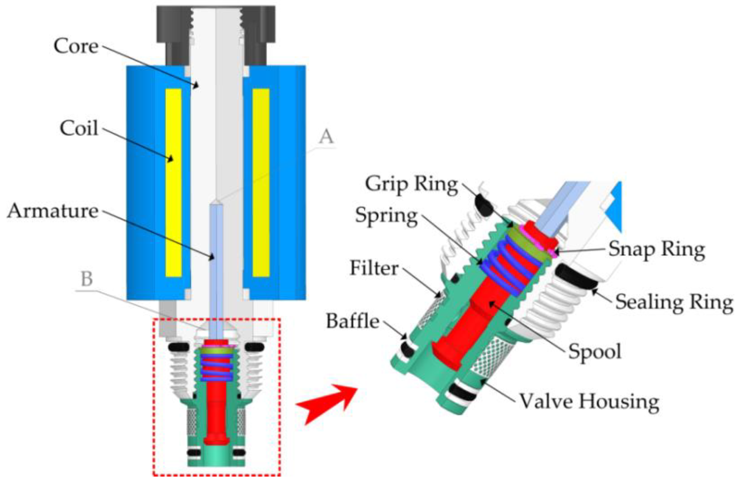
In this research, a typical SCV that is a two-position and two-way normal closed valve is used as the study object, as shown in Figure 1. It can be divided into two parts: a solenoid and a hydraulic on-off valve. The solenoid is mainly composed of core, coil, and armature. The on-off valve consists of spool, valve housing, spring, filter, and so on. When the coil is de-energized, the solenoid does not produce electromagnetic force, and the spool only contacts closely with the valve seat under the action of spring force. At this time, the SCV is off-state, as shown in Figure 2a. The inlet and outlet of the SCV are not connected, which blocks the flow of the hydraulic oil from port P into port T. On the contrary, when the coil is energized, the solenoid generates an electromagnetic force on the armature, which deals with the spring force and pushes the spool to the right. As a result, the spool is opened, as shown in Figure 2b. The two ports of the SCV are connected, and the hydraulic oil flows freely from port P into port T through the annular flow area between the spool and the valve seat. At the same time, the oil in the spring cavity can be exchanged through the elongated hole in the spool to take away the heat generated by the coil, which not only reduces the working temperature of the SCV, but also improves the reliability and service life.

Figure 1.
The structure of solenoid screw-in cartridge valve (SCV) ((A) the armature volume chamber; (B) the spring volume chamber).
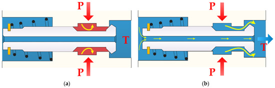
Figure 2.
The flow state of SCV: (a) off-state; (b) on-state.
3. Theoretical Analysis
The SCV is a system affected by the strong coupling of the multi-physics field that includes the electric field, magnetic field, flow field and mechanical movement. Hence, the dynamic characteristics of the SCV can be considered from four respects: mechanical characteristics, electromagnetic characteristics, hydrodynamic characteristics, and circuit properties.
3.1. Mechanical Characteristics
The forces on the armature and the spool are shown in Figure 3. The armature motion is mainly influenced by the electromagnetic force, the spring compression force, etc. The dynamic model of the armature can be written as:
where Fe represents the electromagnetic force produced by the coil, Faap and Fabp are hydraulic force acting on both ends of the armature, respectively. Since the outlet of the SCV is connected to the tank in this work, the pressure of the A and B volume cavities is always zero, namely, Faap = Fabp = 0. Fc is the reaction force of the spool, Favf is the viscous damping of the armature, Faf is the friction force, ma is the quality of armature, and xa is the displacement of the armature.
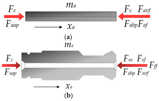
Figure 3.
Dynamic model of the spool: (a) force balance of the armature; (b) force balance of the spool.
Similarly, the dynamic characteristic of the spool can be written as:
where Fsap and Fsbp are the hydraulic pressure on the spool, which is similar to the armature, Fsap = Fsbp = 0. Fss is the compression force of the spring, Fsf is the friction of the spool, Fff is the hydrodynamic force acting on the spool, Fsvf is the viscous damping of the spool, ms is the quality of spool, and xs is the displacement of the spool. Because the armature and spool are so firmly connected during the movement, it can be approximated as xs = xa.
According to Equations (1) and (2), the dynamic characteristic of SCV can be written as:
where m indicates the total weight of the spool and armature, and Ff is the total frictional force on the spool and armature. The spring force is calculated as follows:
where K is the stiffness coefficient of spring and x0 is the initial compression of the spring.
The viscous damping acting on the spool and armature can be written as:
where B is the total viscous damping coefficient of spool and armature.
3.2. Mechanical Characteristics
The electromagnetic force generated by exciting the coil is one of the key parameters of the SCV, which determines the dynamic characteristics of the SCV. The generation of electromagnetic force is a complicated process. In order to quantitatively analyze the electromagnetic force, the following assumptions are made:
- The magnetic resistance of the coil is ignored in order to simplify the model of solenoid coil.
- The electromagnet is the invariably unsaturated state during the spool movement.
- Magnetic flux is uniformly distributed in the air gap when the coil is excited.
Accordingly, the dynamic characteristic of the electromagnetism can be written as:
where I and L are the current and inductance of the solenoid coil, respectively, δ is the air gap of the electromagnet, which refers to the distance between the core of the electromagnet and the two end faces of the stop iron.
It is assumed that the electromagnet is in an unsaturated state, and the inductance of the electromagnetic coil can be written as:
where N is the number of turns of the coil, and Λδ is the magnetic permeability of the air gap, which varies with the magnetic pole shape and the size of the air gap.
From the above assumption 3, the magnetic permeability of the air gap can be written as:
where μ0 is magnetic permeability of vacuum, and S the effective cross sectional area of flux path in the core.
By combining Equations (6)–(8), the electromagnetic force generated by electromagnetic coils can be written as:
3.3. Electric Circuit Characteristics
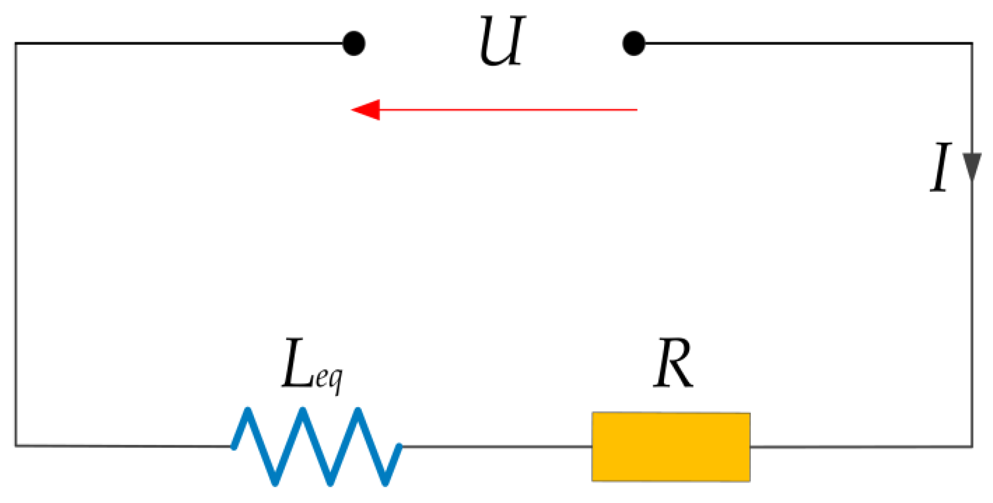
In static conditions (on or off), the solenoid coil can be simplified as a series connection of resistance and inductance, in which the equivalent inductance of the coil can be considered as a constant, as shown Figure 4. The dynamic characteristics of coil based on Kirchhoff’s law can be written as:
where U is excitation voltage of electromagnetic coil, R and Leq are equivalent resistance and inductance of electromagnetic coil. The time-domain expression of the coil current can be solved by Equation (10), as follows:
where Ii is initial current of the coil.

Figure 4.
The equivalent electrical circuit of the SCV.
3.4. Hydrodynamic Characteristics
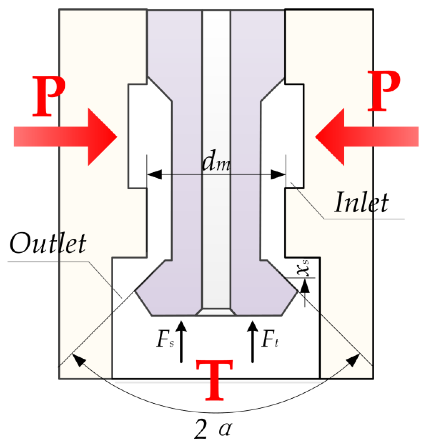
Hydrodynamic force acting on the spool can be divided into steady flow force and transient flow force [29], as shown Figure 5. The steady flow force and transient flow force can be written as:
where Fs and Ft are the steady flow force and transient flow force, respectively. Cd and Cv are the flow coefficient and the fluid velocity coefficient, respectively. dm is the average diameter of the conical spool of the SCV, α is the valve port jet angle, Δp is the pressure difference between the oil passing through the oil inlet and outlet of the cartridge valve, l is the damping length, and ρ is the density of oil.
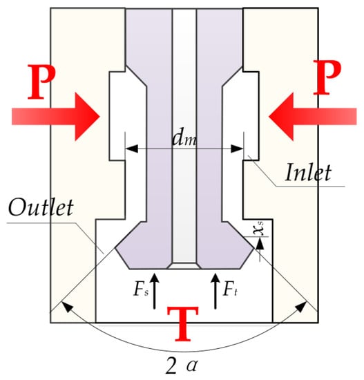
Figure 5.
Schematic diagram of valve core subjected to hydraulic pressure.
Thus, the hydrodynamic force of Fff can be written as:
Due to the SCV being a two-position two-way directional valve, the hydrodynamic force is only considered when the SCV is in the open state, and the valve spool is not affected by the hydrodynamic force when the valve spool is in the closed state.
3.5. Dynamic Characteristic of SCV
Based on previous studies [28], the dynamic characteristic of the SCV switching process is shown in Figure 6. According to the changing trend of spool displacement, the whole dynamic process of the SCV can be compartmentalized into four parts: the spool closing and maintaining stage I, the spool opening stage II, the spool opening and maintaining stage III, and the spool closing stage IV. The spool opening stage II is divided into the spool opening delay stage ① and the spool opening moving stage ②, and the spool closing stage IV is composed of the spool closing delay stage ③ and the spool closing moving stage ④. Moreover, the dynamic change of the coil current is similar to that of spool displacement. Therein, during the spool opening stage II, the change process from the initial coil current to the critical current corresponding to the spool opening delay stage, and the change process from the coil critical current to the coil current when the spool is completely opened corresponds to the spool opening movement stage. Similarly, a corresponding relationship can be set up between the coil current and the spool closing stage. Consequently, the dynamic characteristics of the SCV can be evaluated indirectly by the change of coil current.
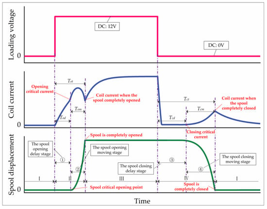
Figure 6.
The dynamic characteristic analysis of SCV.
As the curves in Figure 6 show, the total switching times (Tot and Tct) of spool opening and closing stages, which mainly include the spool opening delay time of Tod, the spool opening moving time of Tom and the spool closing delay time of Tcd, the spool closing moving time of Tcm, determines the opening and closing dynamic characteristics of the SCV. From the curves, we can see that the opening delay time and closing delay time of the spool account for most of the dynamic characteristics of the opening and closing processes, respectively. Therefore, this paper has placed special stress on analyzing and optimizing the opening and closing delay stages to enhance the performance of the SCV.
3.6. Critical Motion Analysis of Spool
At the critical moving moment of the spool, the quantities dxs2/dt2 and dxs/dt are zero. As a result, the dynamic characteristic of SCV can be written as:
where Fce is the critical electromagnetic force. The sign “±” shows the direction of the frictional force, “+” means that the frictional force and electromagnetic force are in the same direction, and “−” means that they are in the opposite direction.
Consequently, when the SCV operates at the critical moment of transitioning from off to on, the dynamic characteristic of the SCV can be written as:
where Foce is the critical electromagnetic force to make the valve spool open. Similarly, when the SCV operates at the critical moment of transitioning from on to off, the dynamic characteristic of the SCV can be written as:
where Fcce is the critical electromagnetic force that causes the valve spool to close.
By combining Equations (9), (16) and (17), the coil critical current during valve spool closing and opening can be written as:
where Iod and Icd are the critical opening current and the critical closing current of the coil respectively, δon and δoff are the air gap when the SCV operates at on and off status, respectively.
Hence, by combining Equations (11), (18) and (19), the delay times of the valve opening and closing processes can be written as:
where Tod and Tcd are the opening delay time and closing delay time, Lon and Loff are the equivalent inductance of the electromagnetic coil when HSV operates at on and off status, Uon and Uoff are the opening and closing excitation voltages of the solenoid coil, Iio and Iic are the initial opening current and initial closing current of the electromagnetic coil, respectively.
It can be seen from Equations (20) and (21) that large values of initial currents and excitation voltages have a positive effect on the opening dynamic characteristics of the SCV, which reduces the opening delay time of Tod. On the contrary, the small values of initial currents and excitation voltages are helpful to reduce the closing delay time of Tcd. Furthermore, negative voltages are even more effective for rapidly decreasing the coil current in the closing process.
4. Control Strategy and Simulation Model
4.1. Hybrid Voltage Control
In order to improve the dynamic characteristics of the SCV, a novel hybrid voltage control strategy is proposed and shown in Figure 7. The hybrid voltage control strategy consists of four components: preloading voltage (PV), positive pulse voltage (PPV), holding voltage (HV) and negative pulse voltage (NPV). Each component of the hybrid voltage corresponds to the four stages of spool displacement and serves a distinct purpose, as shown below:
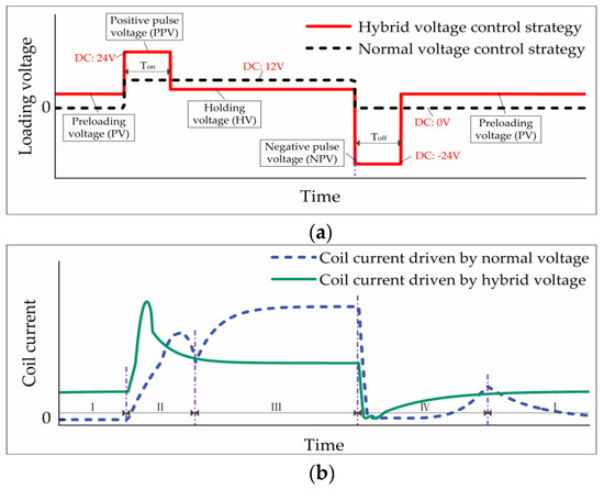
Figure 7.
Comparison of hybrid voltage control strategy and normal voltage control strategy: (a) the voltage of solenoid coil; (b) the current of solenoid coil.
- The PV reduces the time from the initial current to the critical current by increasing the initial current of the coil, to shorten the spool opening delay time Tod.
- The PPV accelerates the change rate of coil current, resulting in less spool movement time Tom.
- The reduction of the HV, based on the concept of keeping the spool open, helps to decrease the coil initial current of the spool closing stage, which results in some decrease in the closing delay time Tcd.
- The NPV enhances the decreasing rate of coil current and minimizes the blocking effect of coil eddy current on the spool closing stage for the sake of cutting the spool closing moving time Tcm.
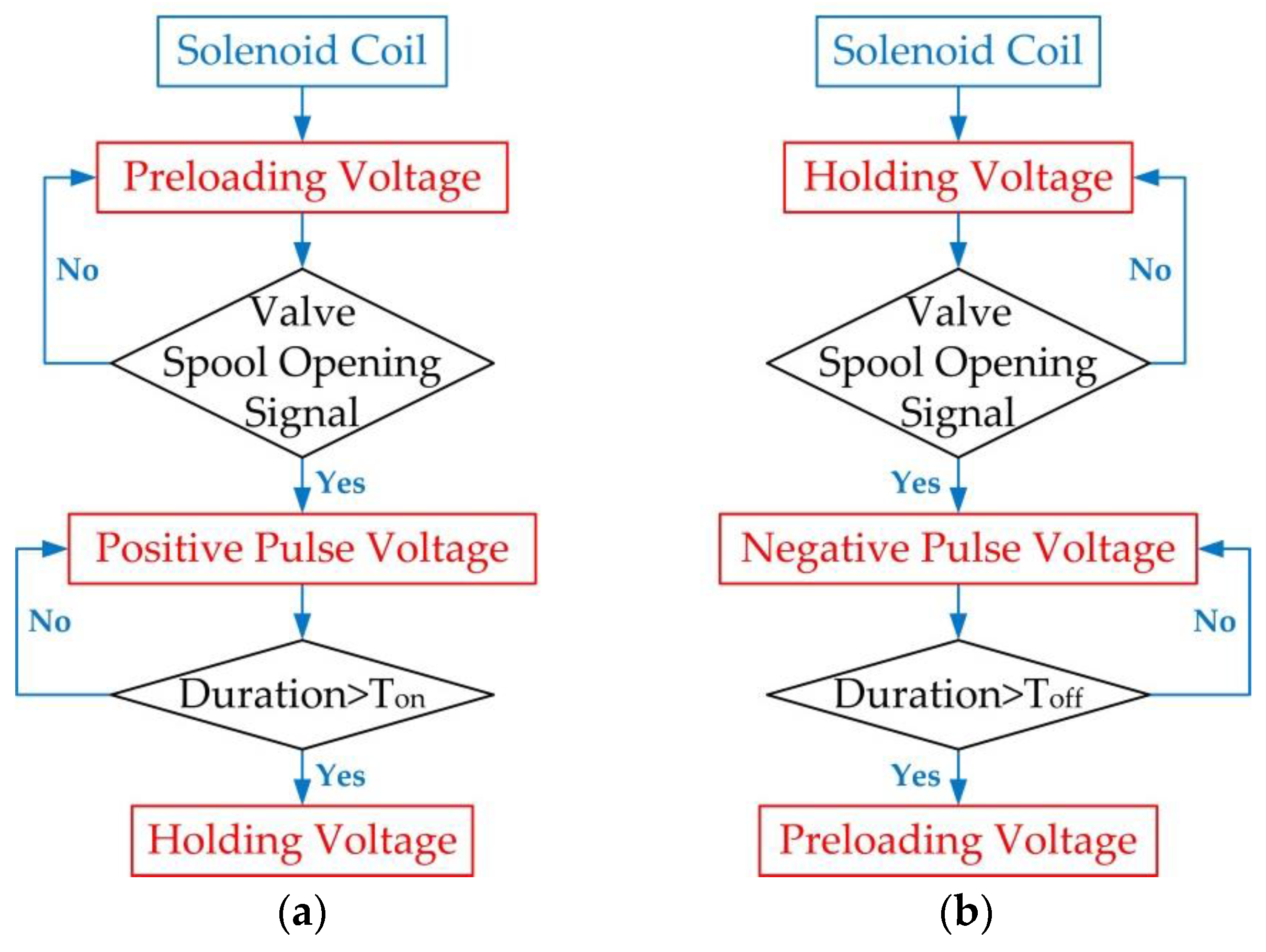
The voltage mechanism of the hybrid voltage control strategy is shown in Figure 8. When the spool of the SCV transits from the closed state to the open state, the electromagnetic coil of the SCV is first excited by the PV. As a result, the initial opening current of the electromagnetic coil is not zero. Since the initial opening current is less than the critical opening current of the SCV, the SCV is still in a closed state. When the SCV controller receives the spool open signal, the excitation voltage of the coil changes from preloading voltage to positive pulse voltage, making the coil current increase rapidly. Enough electromagnetic force has arisen to make the spool open quickly. When the duration of positive pulse voltage reaches a set value of Ton, the working voltage of the coil becomes the holding voltage, but the spool is still at the open position. Similar to the spool opening process, the solenoid coil is subjected to holding voltage, negative pulse voltage and preloading voltage when the spool changes from the open state to the closed state, respectively. As the SCV works again, the electromagnetic coil is again excited by the voltage at each stage of the hybrid voltage control strategy.
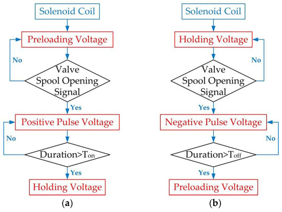
Figure 8.
The voltage switching mechanism of hybrid voltage control: (a) valve spool opening process; (b) valve spool closing process.
4.2. Modeling and Experiment Verification
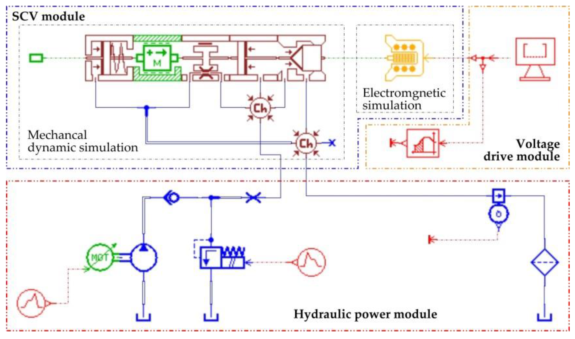
In order to evaluate the validity of the proposed control strategy and optimize the control parameters, the SCV, as well as the test system, were modeled by using AMESim. The simulation model, as illustrated in Figure 9, is divided into three main parts: the SCV module, voltage drive module, and hydraulic power module. Among them, the model of the SCV is composed of the mechanical dynamic model and electromagnetic simulation model. In the meantime, some signal and control components are used to produce the appropriate drive voltage required by hybrid voltage control.
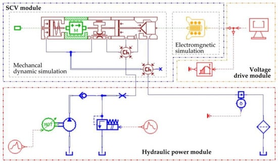
Figure 9.
The simulation model of the SCV.
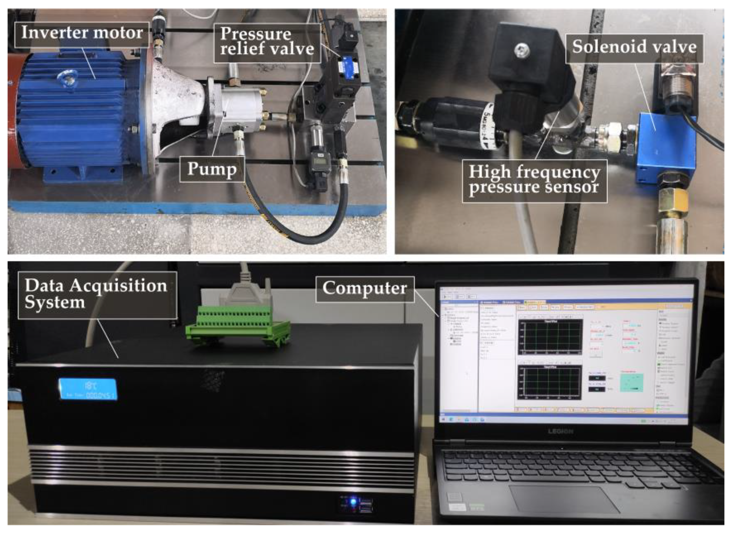
According to the performance parameters of the selected SCV, a test rig for verifying the accuracy of the simulation model was designed and built, as shown in Figure 10. The experimental setup was divided into two main parts: control block, hydraulic block. The control module based on a data acquisition system and a host computer was used to generate control signals and collect sensor signals. The hydraulic block was mainly composed of an inverter motor, pump, relief valve, pressure sensors, and solenoid screw-in cartridge valve. The main parameters of the significant parts in this rig are shown in Table 1. For the sake of simplifying the control power supply, DC 24 V power and PWM technology were employed to offer drive voltage to the SCV.
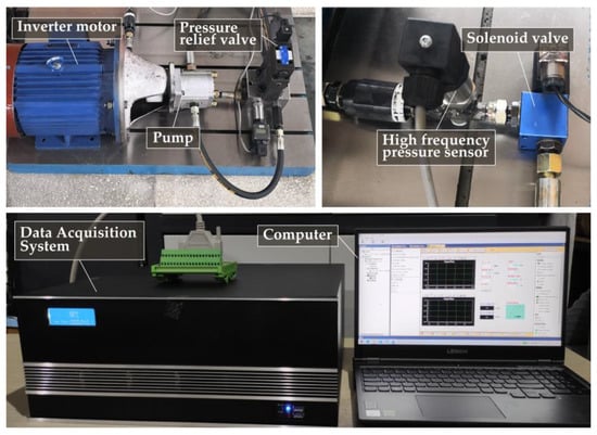
Figure 10.
Experimental system of SCV.

Table 1.
Main performance parameters.
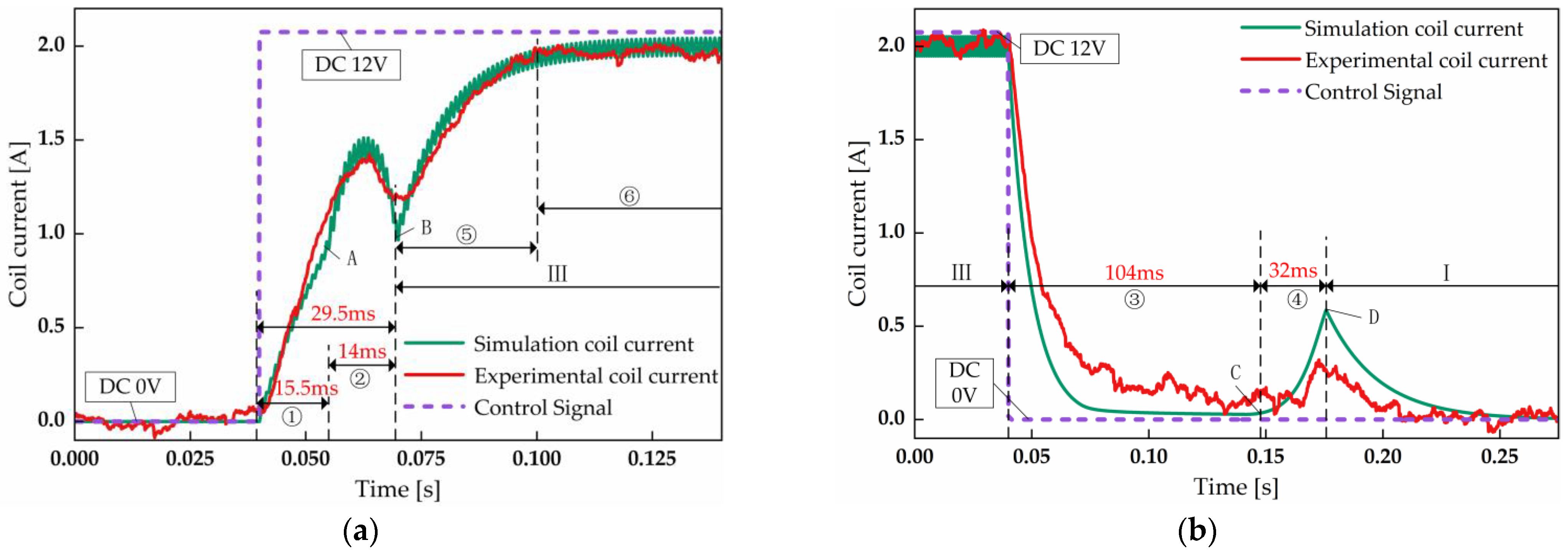
The nominal voltage of 12 V achieved by the use of DC 24 V, frequency 1000 Hz and duty cycle 50% was applied to the SCV to compare the results of the simulation and experiment that are shown in Figure 11. As shown in Figure 11a, the experimental results of coil current are consistent with the simulation ones. In the opening process, the delay time and moving time are 15.5 ms and 14 ms, respectively, which brings about the total opening time of 29.5 ms. Figure 11b shows the variation of the coil current in the closing process. It can be seen that the closing delay times of the experimental and simulated are all 104 ms, which badly affects the dynamic characteristics of the spool closing. The closing moving time of the experiment is almost the same as that of the simulations, which is equal to 32 ms. Based on the above analysis, it can be concluded that the established simulation model is feasible and can be used to analyze the dynamic characters of the SCV.
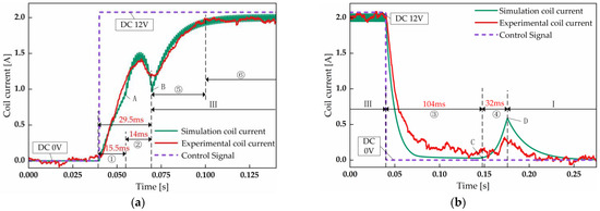
Figure 11.
Simulation and experiment result with nominal voltage: (a) opening process; (b) closing process(①: the spool opening delay stage; ②: the spool opening moving stage; ③: the spool closing delay stage; ④:the spool closing moving stage; ⑤: the coil current rising stage when the spool is fully opened; ⑥: the coil current holding stage when the spool is fully opened; A: opening critical current; B: coil current when the spool completely opened; C: closing critical current; D: coil current when the spool completely closed; I: the spool closing and maintaining stage; III: the spool opening and maintain stage).
5. Simulation Results
5.1. Loading Voltage and Duty Cycle
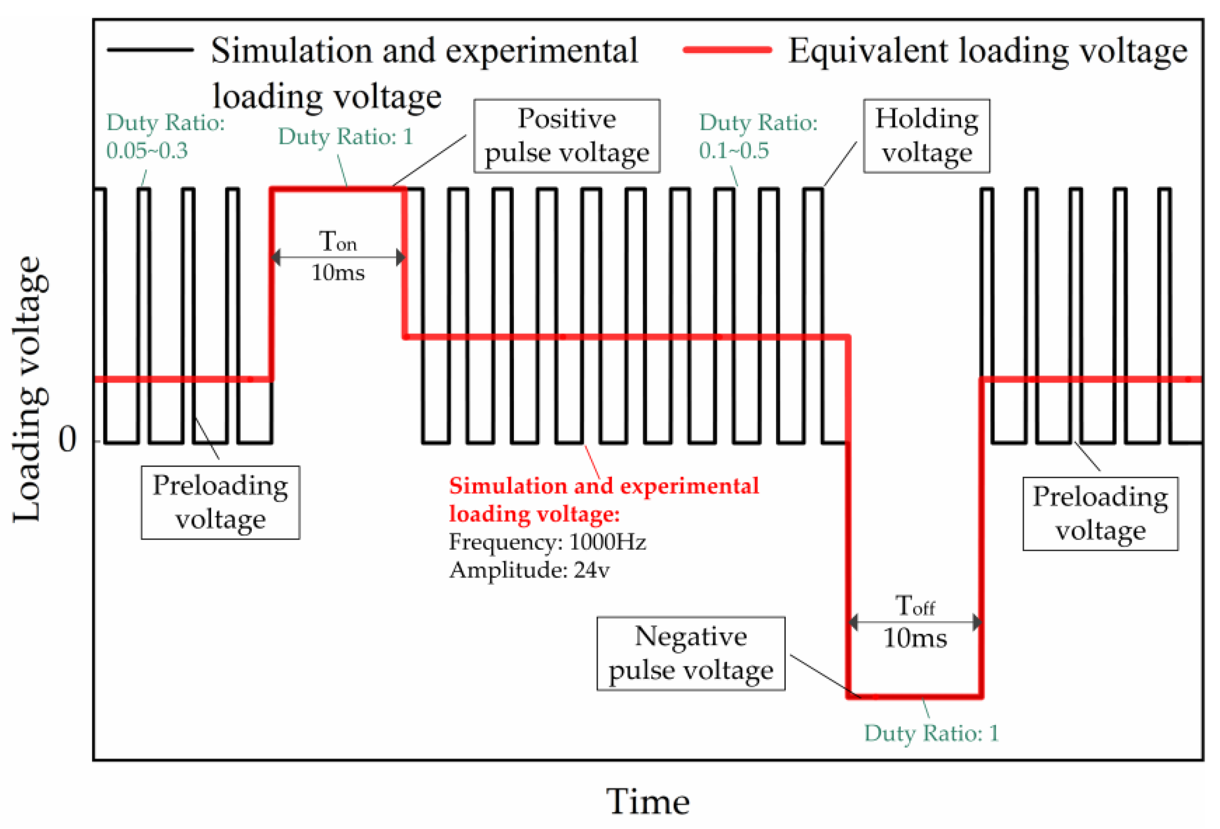
In our previous studies [28], the effects of the PPV and NPV on the open–close dynamic characteristics of the SCV have been investigated. It was found that the SCV achieves the optimal dynamic characteristics when the duration of the 24 V PPV and 24 V NPV is both 10 ms, which was also used in this work. That is, the duty cycle of PPV and NPV is equal to one. According to the theoretical study in the third section, the opening and closing dynamic characteristics of the SCV are greatly impacted by preloading voltage and holding voltage applied to the coil. Hence, the duty cycle of the PV and HV is regulated to explore the change law of the dynamic characteristics of the SCV with the different initial opening and closing coil currents. The duty cycle and equivalent loading voltage at each stage of the SCV switching process are shown in Figure 12.
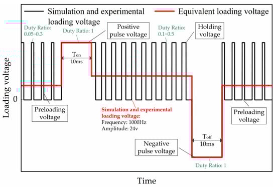
Figure 12.
Loading voltage and duty cycle in the simulation.
5.2. Effects of the Duty Ratio of Preloading Voltage (PV) on Dynamic Characteristics of the SCV
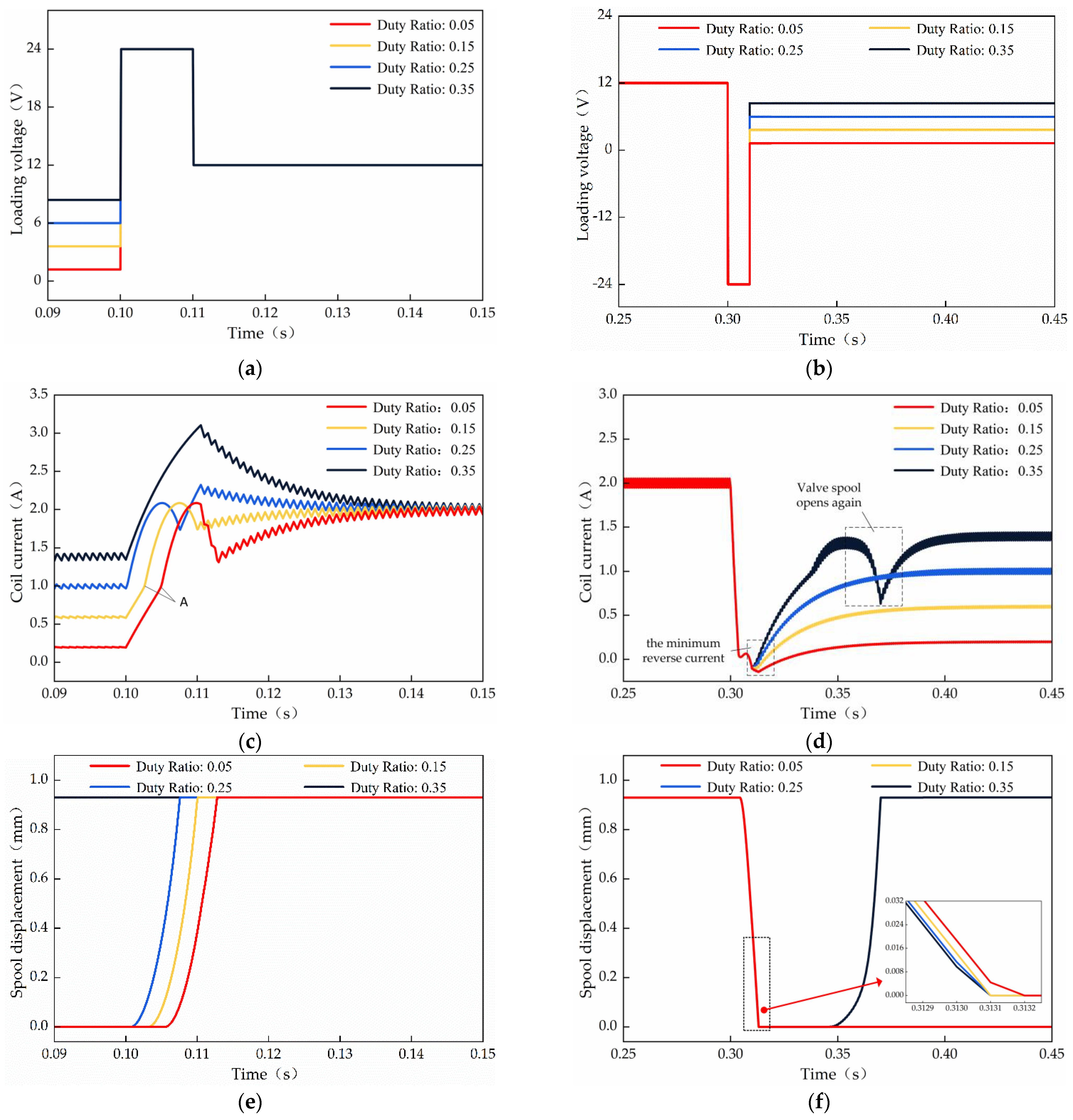
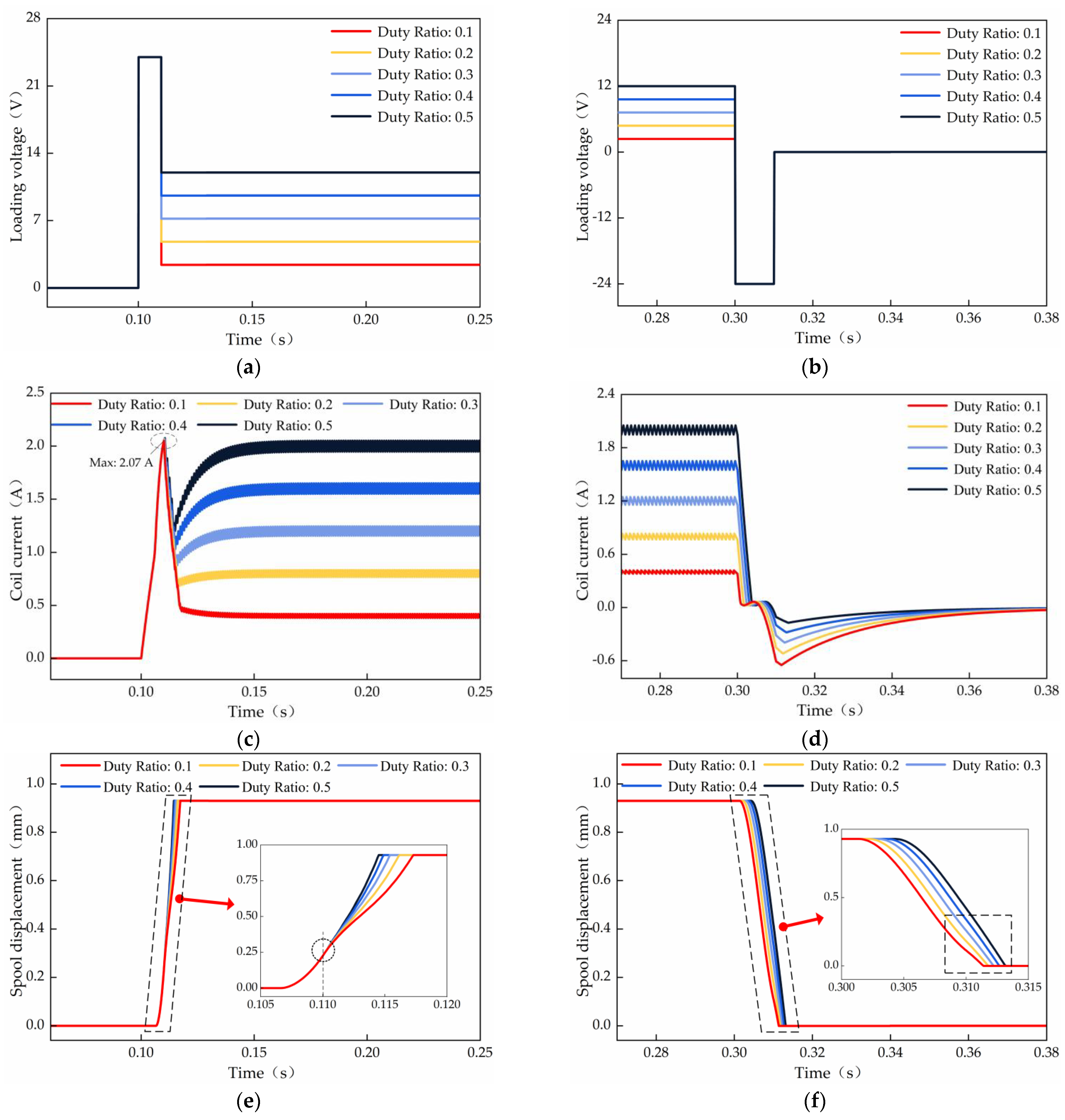
The opening and closing control signals of the SCV are provided at 0.1 s and 0.3 s, respectively, and the dynamic responses of the SCV with different duty ratios of PV, from 0.05 to 0.35, are shown in Figure 13. From pictures (a) and (c) of Figure 13, it can be seen that the operating voltage of the coil rises proportionally with the increase of the PV duty ratios, which raises the initial coil current. For this reason, the opening delay time for the coil current from the initial current to the critical moving current gradually decreases in the opening process of the SCV, but the coil current of SCV remains largely the same during the spool opening moving stage, which is also indicated by the translation motion to the left of the spool displacement curve displayed in picture (e) of Figure 13. As a result, the total switching time of the SCV opening process is effectively squeezed. Nevertheless, there are concerns that the maximum value of the coil current has been a sharp rise when the PV duty cycle exceeds a certain critical value, which can damage the solenoid of the SCV. The reason for this phenomenon represented by 0.35 duty cycle is the shortened total opening time of SCV of less than 10 ms, which causes the coil to be still excited by 24 V after the spool is fully opened. From the curves in Figure 13b,d, the coil current of the closing delay stage is not affected by the variation of the PV duty ratios, but the minimum reverse current of the coil decreases slightly during the closing moving stage of the spool. After the spool is completely closed, however, the spool opens again with the coil current sudden change under the too big PV duty cycle, as shown in the duty cycle 0.35 curve of Figure 13f. This is because the preloading voltage is too large, and the current in the coil exceeds the critical current, which generates a large enough electromagnetic force to overcome the resistance blocking the spool movement.
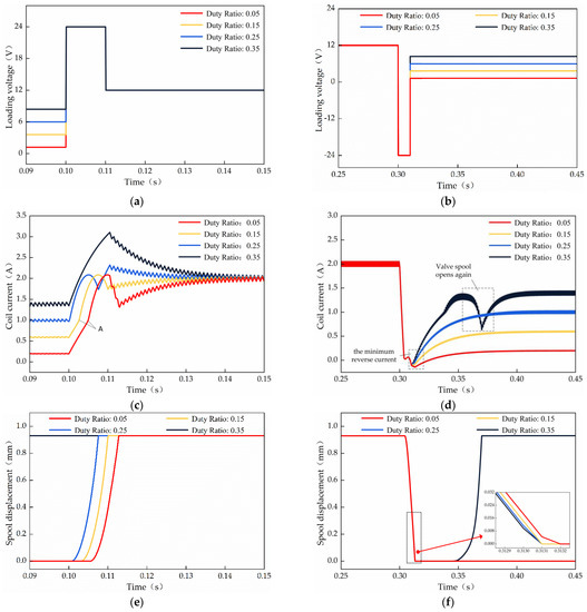
Figure 13.
Dynamic responses of the SCV with different preloading value (PV) duty ratios in the opening and closing process: (a,b) coil voltage; (c,d) coil current; (e,f) spool displacement.
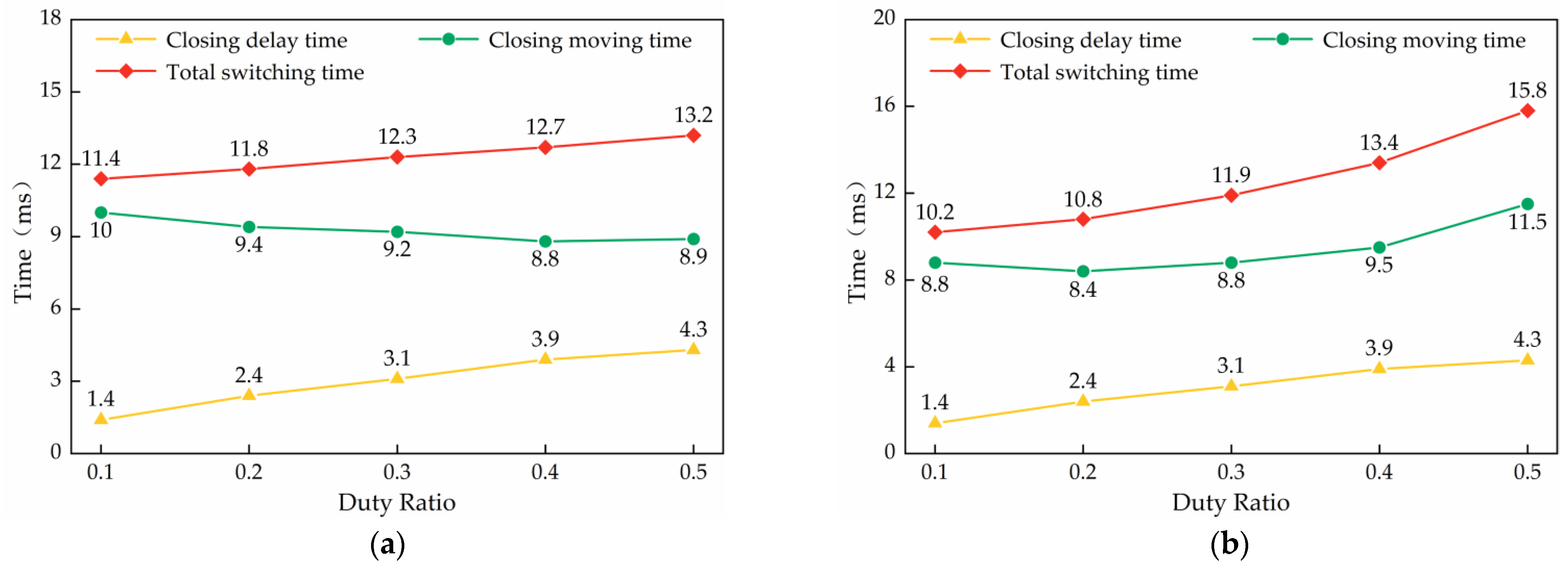
The results of the each stage duration of the spool in the opening process are shown in Figure 14. It is easily observable that the opening moving time changes very little, which decreases only from 7.4 ms to 6.6 ms with the PV duty ratio increasing from 0.05 to 0.25. However, the opening delay time of the spool decreases sharply from 5.5 ms to 1 ms with the same duty ratio change. Thus, the total switching time of the SCV also rapidly reduced from 12.9 ms to 7.6 ms. The opening dynamic performance of the SCV has been improved by 41.09%. The 0.25 is chosen as the final duty ratio for the PV to reach the best opening performance of the SCV. With regard to the total closing time of the SCV, it is almost unchanged, from 13.2 ms to 13.1 ms, by using the 0.25 duty ratio of the PV.
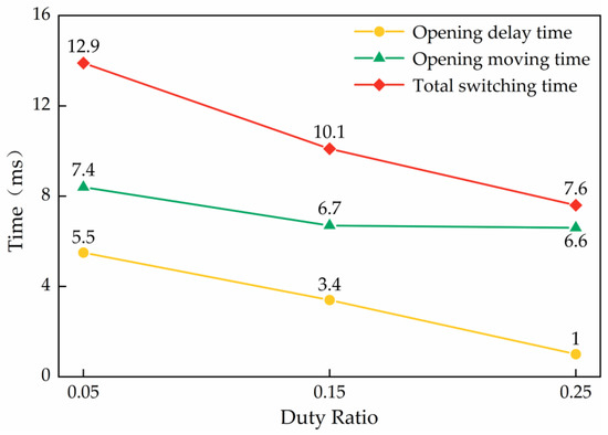
Figure 14.
The each stage time of the spool opening process with different PV duty ratios.
5.3. Effects of the Duty Ratio of Holding Voltage (HV) on Dynamic Characteristics of the SCV
The effects of the different HV duty ratios on the dynamic performance of the SCV are shown in Figure 15. The signals for controlling the SCV on and off are produced at the moments of 0.1 s and 0.3 s. From Figure 15a,c, the maximum current of the coil is almost constant at 2.07 A in the spool opening moving phase. After the spool is completely opened, the holding current of the coil is low with the decrease of the HV duty cycle from 0.5 to 0.1. As can be seen from the curves in Figure 15b,d, the time spent by the coil current from the initial closing current to the critical closing current decreases gradually correspondingly, which can also prove that the spool closing delay time shortens as the duty cycle of the holding voltage decreases from Figure 15f. Under the condition that the negative pulse voltage duration remains at the original 10 ms, the time that the coil is excited by the −24 V voltage gradually increases with the decrease of the HV duty cycle in the spool closing moving phase. As a result, an undesirable reverse coil current that gradually increases with the decrease of the HV duty cycle occurs, which yields electromagnetic force acting on the valve spool and puts off the closing motion of the spool. For the spool closing moving stage, for example, the spool displacement curve changes abruptly with a duty cycle of 0.1, and the closing moving time of the spool becomes longer. However, the spool displacement curve has the same trend at high HV duty ratios, such as the duty cycle of 0.5 and 0.4. However, overall, the reduction of the HV duty cycle is not only beneficial to improve the closing dynamic characteristics of the SCV, but also abates the energy consumption of the opening and holding stage of the spool. It is simultaneously known that the 10 ms duration of the negative pulse voltage is too big for the small HV duty cycle. Consequently, in order to further improve the closing dynamic performance of the SCV, the duration of the negative pulse voltage is optimized from 10 ms to 7 ms.

Figure 15.
Dynamic responses of the SCV with different holding voltage (HV) duty ratios: (a,b) coil loading voltage; (c,d) coil current; (e,f) spool displacement.
Before and after the duration optimization of negative pulse voltage, each stage of the simulated results of the spool in the closing process is illustrated in Figure 16, with the different HV duty ratios. As the curves in Figure 16a show, with the decrease of the HV duty ratio the closing delay time and the total closing time have the same trend, decreasing from 4.3 to 1.4 and from 13.2 to 11.4 ms, respectively. However, the closing moving time of the spool rises from 8.9 to 10 ms, which counteracts the positive effects of the reduction of the spool closing delay time. When the 7 ms negative pulse voltage is used in the spool closing process, it can be seen from Figure 16b that the spool closing moving time has a downward trend as the HV decreases. In the case of the 0.1 HV duty cycle, the SCV has a minimum total closing time of 10.2 ms that includes a 1.4 ms closing delay time and an 8.8 ms closing moving time. Compared to the optimized total switching time with the same 0.1 duty ratio, the total closing time before the optimization is reduced by 10.53%, from 11.4 ms to 10.2 ms.
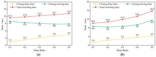
Figure 16.
The each stage time of the spool closing process with different HV duty ratios: (a) before optimization (10 ms); (b) optimized (7 ms).
5.4. Comparison of Three Control Methods
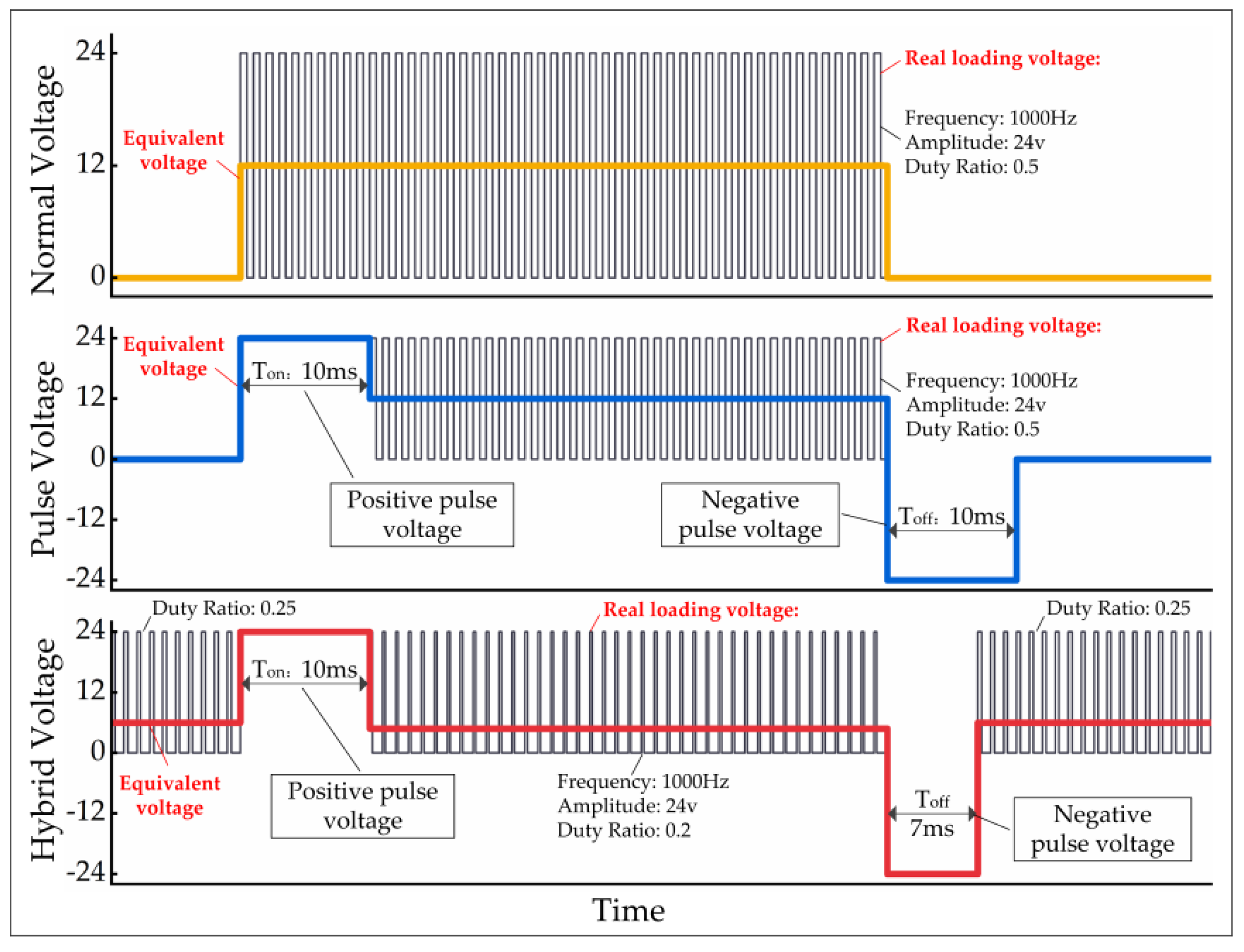
To reveal the effectiveness of the proposed hybrid voltage control, comparative simulations are implemented under the different control strategies: normal voltage, pulse voltage, and hybrid voltage. The three control strategies are demonstrated in more detail in Figure 17. Every control scheme is realized by altering the duty ratio of PWM of the DC 24 V power supply. The parameters of each control strategy are provided below.
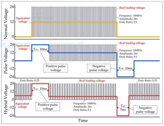
Figure 17.
Detailed parameters of the three control voltages.
Strategy 1: Normal voltage control strategy consists of preload voltage and holding voltage. According to the rated operating parameters of the cartridge valve, the preload voltage duty cycle is set to 0, while the holding voltage duty cycle is set to 0.5.
Strategy 2: Pulsed voltage control strategy was discussed by Daling Yue’s team at Lanzhou University of Technology for SCVs to improve its control dynamic characteristics, in which the duty cycles of preloading voltage and holding voltage are 0 and 0.5, and the duty ratios of positive pulse voltage and negative pulse voltage are 1. The durations of Ton and Toff are set at 10 ms.
Strategy 3: Hybrid voltage control strategy is similar to the pulse voltage control strategy in that it consists of a preloading voltage, a positive pulse voltage, a holding voltage and a negative pulse voltage. The preloading voltage and the holding voltage are adjusted at 0.25 and 0.2, respectively, based on the simulation findings ahead. The duty ratio of positive and negative pulse voltages remain the same, while the durations of Ton and Toff are adjusted to 10 ms and 7 ms, respectively.
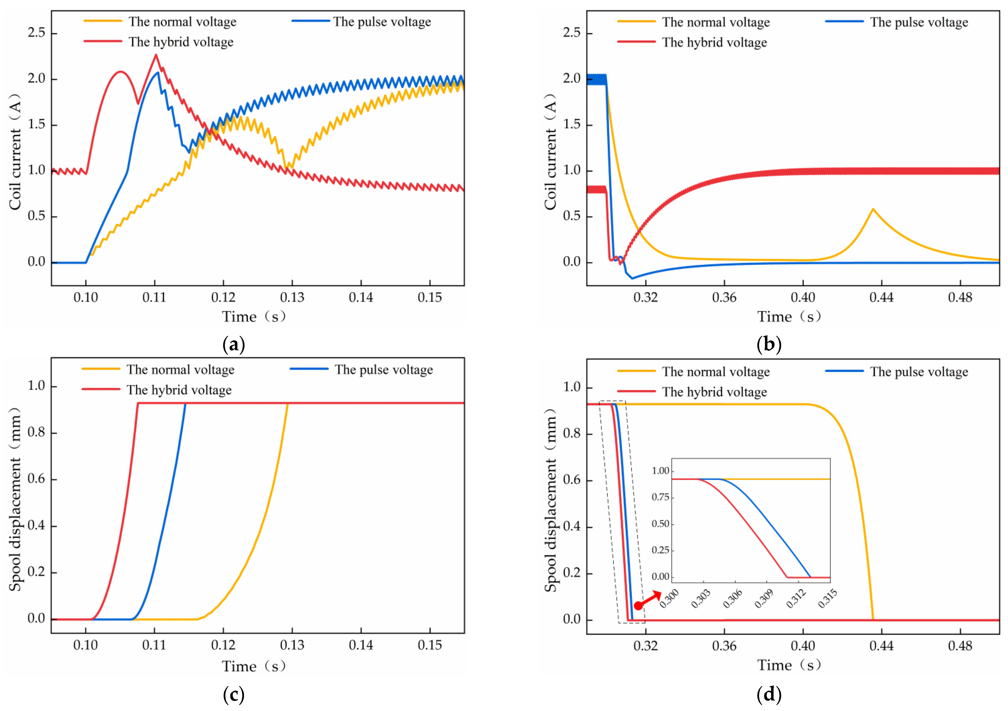
Comparisons of simulation results of the SCV dynamic characteristics under the three different control strategies are shown in Figure 18. For the spool opening process as shown in Figure 18a,c the pulse control has a bigger coil current slope than that of the normal voltage, which not only advances the time that the spool begins to move but also promotes the opening movement of the spool. Consequently, the opening delay and opening movement times of the SCV are simultaneously compressed. The major difference between the hybrid voltage and pulse voltage is the preloading voltage, which allows the initial coil current to near the critical moving current and would greatly diminish the opening delay time. From the coil current and spool displacement curves in Figure 18b,d, the sharp decline of the coil current in the closing process verified that the negative pulse voltage works effectively. For the hybrid voltage control, the addition of the lower HV duty cycle results in the initial closing current becoming small, which slightly reduces the closing delay time of the SCV. Through the displacement contrast analysis of the spool opening and closing process, the SCV has brought about varying degrees of improvement in dynamic performance by using the three controls.
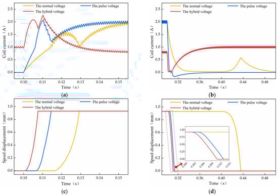
Figure 18.
Dynamic characteristics comparison of three control strategies: (a) coil current of the opening process; (b) coil current of the closing process; (c) spool displacement of the opening process; (d) spool displacement of the closing process.
The detailed comparisons of performance parameters with the three controls are shown in Table 2. From the spool opening results, the opening delay time has dipped from 15.5 ms to 1.0 ms, and the opening moving time has decreased from 14.0 ms to 6.6 ms by employing the hybrid voltage, which has been improved by 93.55% and 52.86%. The total opening time also falls dramatically 74.24%, from 29.5 ms to 7.6 ms. Compared with the pulse voltage control, the opening delay and moving performance are heightened by 85.07% and 15.38%, respectively. Replacing the normal voltage by hybrid voltage, the spool closing delay and moving time are considerably decreased from 104 ms to 1.9 ms and 32 ms to 8.9 ms, which changes by 98.17% and 72.19%, respectively. Accordingly, the closing dynamic performance of the SCV is enhanced from 136 ms to 10.8 ms, by 92.06%. It is clear that the major contribution of the hybrid voltage method in the spool closing process is that the closing delay performance increased by 55.81%.
Table 2.
Comparison of performance parameters under three control strategies.
6. Conclusions
The hybrid voltage control method consisting of preloading voltage, positive pulse voltage, holding voltage and negative pulse voltage is put forward and applied to the usual commercial screw-in cartridge valve to raise its dynamic response so that the SCV can be suitable for digital hydraulics. The performance comparisons of the normal voltage, pulsed voltage and hybrid voltage control proved that the hybrid voltage control has a better effect than the other two. Under hybrid voltage control, the total opening time of the SCV changes from 29.5 ms to 7.6 ms, and the total closing time becomes 10.8 ms from 136 ms, which not only confirms the effectiveness of the control strategy proposed in this paper, but also allows the SCV the opportunity to replace HSV in digital hydraulic systems. The following conclusions are drawn:
- An excessive preloading voltage will cause the spool to open by mistake. While keeping the SCV shut, the bigger preloading voltage is beneficial to the decrease of the opening delay time.
- Under the spool opening conditions, reducing the holding voltage can effectively improve the closing delay characteristic of the SCV.
- With the addition of the preloading and holding voltages, some adjustment of the positive and negative pulse voltage duration may be necessary to avoid the coil always working in 24 V after the spool opening, or the spool opening once again after closing.
It can be seen from the research that the spool delay time has been squeezed as much as possible. In order to further enhance the dynamic response of the SCV, in depth work on improving the spool moving performance of the SCV is underway in our laboratory to eliminate the dynamic properties gap between SCVs and HSVs.
Author Contributions
Conceptualization, L.W. and Z.L.; methodology, L.W.; software, D.Y. and L.L.; validation, D.Y., L.L. and Z.L.; formal analysis, L.W. and Z.L.; investigation, C.L. and X.Z.; resources, L.W.; data curation, Z.L. and L.L.; writing—original draft preparation, D.Y. and L.L.; writing—review and editing, Z.L.; visualization, L.L.; supervision, Z.L.; project administration, Z.L.; funding acquisition, L.W. and D.Y. All authors have read and agreed to the published version of the manuscript.
Funding
This research was funded by the National Key R&D Program of China (Grant No. 2020YFB2009803).
Institutional Review Board Statement
Not applicable.
Informed Consent Statement
Not applicable.
Data Availability Statement
Not applicable.
Conflicts of Interest
The authors declared no potential conflict of interest with respect to the research, authorship, and publication of this article.
References
- Hua-Yong, Y.; Min, P. Engineering research in fluid power: A review. J. Zhejiang Univ. Sci. A 2015, 16, 427–442. [Google Scholar] [CrossRef] [Green Version]
- Laamanen, M.S.A.; Vilenius, M. Is it time for digital hydraulics. In Proceedings of the Eighth Scandinavian International Conference on Fluid Power, Tampere, Finland, 7–9 May 2003. [Google Scholar]
- Taghizadeh, M.; Ghaffari, A.; Najafi, F. Modeling and identification of a solenoid valve for PWM control applications. Comptes Rendus Mec. 2009, 337, 131–140. [Google Scholar] [CrossRef]
- Aihong, M.; Xiang, G.; Nannan, L.; Charles, G. Study on the Effect of Structural Parameters on the Linear Control Performance of High Speed On-Off Valve Based on Flow Field Analysis. SAE Tech. Pap. Ser. 2020, 01, 1644–1651. [Google Scholar]
- Passarini, L.C.; Nakajima, P.R. Development of a high-speed solenoid valve: An investigation of the importance of the armature mass on the dynamic response. J. Braz. Soc. Mech. Sci. Eng. 2003, 25, 329–335. [Google Scholar] [CrossRef]
- Sturman, O.E. Sturman Digital Systems LLC. Digital Fuel Injector, Injection and Hydraulic Valve Actuation Module and Engine and High Pressure Pump Methods and Apparatus. U.S. Patent 7,568,633, 4 August 2009. [Google Scholar]
- Uusitalo, J.-P.; Ahola, V.; Soederlund, L.; Linjama, M.; Juhola, M.; Kettunen, L. Novel bistable hammer valve for digital hydraulics. Int. J. Fluid Power 2010, 11, 35–44. [Google Scholar] [CrossRef]
- Shuai, W.; Xiangyu, Z.; Chunfang, L.; Zongxia, J.; Fengyu, Q. Multiobjective Optimization of a Hollow Plunger Type Solenoid for High Speed On/Off Valve. IEEE Trans. Ind. Electron. 2018, 65, 3115–3124. [Google Scholar]
- Haibing, J.; Jian, R.; Sheng, L.; Xiqing, Z.; Ying, C. Design and Experiment of 2D Electrohydraulic High-speed On-off Valve. Trans. Chin. Soc. Agric. Mach. 2015, 46, 328–334. [Google Scholar]
- Tu, H.C.; Rannow, M.B.; Wang, M.; Li, P.Y.; Chase, T.R.; Van De Ven, J.D. Design, modeling, and validation of a high-speed rotary pulse-width-modulation on/off hydraulic valve. J. Dyn. Syst. Meas. Control. 2012, 134, 061002. [Google Scholar] [CrossRef] [Green Version]
- Guowen, L.; Jian, R.; Shen, L.; Bin, M. Design and experimental study of two-dimensional (2D) electro-hydraulic proportional directional valve. In Proceedings of the 2015 International Conference on Fluid Power and Mechatronics (FPM), Harbin, China, 5–7 August 2015; pp. 276–282. [Google Scholar]
- Xiaowu, K.; Shizhen, L. Dynamic performance of high speed solenoid valve with parallel coils. Chin. J. Mech. Eng. 2014, 27, 816–821. [Google Scholar]
- Qilei, W.; Fengyu, Y.; Qian, Y.; Junhui, C.; Hongyan, G. Experimental analysis of new high-speed powerful digital solenoid valves. Energy Convers. Manag. 2011, 52, 2309–2313. [Google Scholar]
- Meng, A. Design of pulsed jet on-off valve based on giant magnetostrictive actuator. In Proceedings of the International Conference on Integration and Commercialization of Micro and Nanosystems, Sanya, China, 10–13 January 2007; pp. 397–401. [Google Scholar]
- Juntao, Y.; Zongxia, J.; Shuai, W. Design. Simulation and Test of High-flow High-speed on/off Valve Driven by Piezoelectric. J. Mech. Eng. 2020, 56, 226–234. [Google Scholar] [CrossRef]
- Xiaoming, C.; Yuchuan, Z.; Zhang, L.; Renqiang, L.; Minghao, T.; Changwen, W. Characteristic investigation of a magnetostrictive fast switching valve for digital hydraulic converter. Proc. Inst. Mech. Eng. Part I J. Syst. Control. Eng. 2021, 235, 190–206. [Google Scholar]
- Liyi, L.; Chengming, Z.; Baiping, Y.; Xiaopeng, L. Research of a giant magnetostrictive valve with internal cooling structure. IEEE Trans. Magn. 2011, 47, 2897–2900. [Google Scholar] [CrossRef]
- Can, Z.; Ji-An, D.; Guiling, D.; Junhui, L. A novel high-speed jet dispenser driven by double piezoelectric stacks. IEEE Trans. Ind. Electron. 2016, 64, 412–419. [Google Scholar]
- Pellikka, M.; Ahola, V.; Soederlund, L.; Uusitalo, J.-P. Genetic optimization of a fast solenoid actuator for a digital hydraulic valve. Int. J. Fluid Power 2011, 12, 49–56. [Google Scholar] [CrossRef]
- Sato, Y.; Sato, S.; Tanaka, H. High Speed Switching of a High Response On/Off Solenoid Valve. Proc. JSME Mech. Control. Conf. B 1993, 930–942, 560–965. [Google Scholar]
- Ill-Yeong, L. Switching response improvement of a high speed on/off solenoid valve by using a 3 power source type valve driving circuit. In Proceedings of the 2006 IEEE International Conference on Industrial Technology, Mumbai, India, 15–17 December 2006; IEEE: Piscataway, NJ, USA, 2006; pp. 1823–1828. [Google Scholar]
- Ming, S. Investigation on Control Characteristics and Method of Solenoid High Speed On/Off Valve. Ph.D. Thesis, Guizhou University, Guiyang, China, 2010. [Google Scholar]
- Jianhui, Z.; Meiling, W.; Zhangjun, W.; Grekhov, L.; Tao, Q.; Xiuzhen, M. Different boost voltage effects on the dynamic response and energy losses of high-speed solenoid valves. Appl. Therm. Eng. 2017, 123, 1494–1503. [Google Scholar]
- Jianhui, Z.; Pengfei, Y.; Grekhov, L.; Xiuzhen, M. Hold current effects on the power losses of high-speed solenoid valve for common-rail injector. Appl. Therm. Eng. 2018, 128, 1579–1587. [Google Scholar]
- Qiang, G.; Yuchuan, Z.; Zhang, L.; Bruno, N. Investigation on adaptive pulse width modulation control for high speed on/off valve. J. Mech. Sci. Technol. 2020, 34, 1711–1722. [Google Scholar]
- Qiang, G.; Yuchuan, Z.; Zhang, L.; Xiaoming, C. Analysis and optimization on compound PWM control strategy of high-speed on /off valve. J. Beijing Univ. Aeronaut. Astronaut. 2019, 45, 1129–1136. [Google Scholar]
- Bin, Z.; Qi, Z.; Ji-En, M.; Hao-Cen, H.; Hui-Ming, B.; Yan, S.; Hua-Yong, Y. Self-correcting PWM control for dynamic performance preservation in high speed on/off valve. Mechatronics 2018, 55, 141–150. [Google Scholar]
- Daling, Y.; Linfei, L.; Liejiang, W.; Zengguang, L.; Chao, L.; Xiukun, Z. Effects of Pulse Voltage Duration on Open–Close Dynamic Characteristics of Solenoid Screw-In Cartridge Valves. Processes 2021, 9, 1722. [Google Scholar]
- Merritt, H. Hydraulic Control Systems; John Wiley & Sons: Hoboken, NJ, USA, 1991; pp. 90–92. [Google Scholar]


Publisher’s Note: MDPI stays neutral with regard to jurisdictional claims in published maps and institutional affiliations. |
© 2022 by the authors. Licensee MDPI, Basel, Switzerland. This article is an open access article distributed under the terms and conditions of the Creative Commons Attribution (CC BY) license (https://creativecommons.org/licenses/by/4.0/).