Abstract
The core of the ultrasonic machining system is the acoustic vibration component. Due to the inconsistency of the assembly conditions between the junction surfaces of the acoustic vibration component, the resonant frequency of the ultrasonic acoustic vibration component after the size adjustment of the ultrasonic horn is low, and the Impedance mismatch occurs in the ultrasonic system. In this paper, considering the influence of assembly conditions, the optimal assembly parameters were studied to reduce the junction surface’s influence on the ultra-sonic horn’s performance parameters. The paper analyzed the assembly structure, assembly parameters, and static and dynamic performance parameters of the acoustic vibration components and established a static and dynamic performance parameter measurement system. The assembly parameters of the ultrasonic acoustic vibration components were analyzed and determined. The static performance parameters of the ultrasonic acoustic components were measured and analyzed for the assembly parameters of the junction surface at the ultrasonic horn and the straight-edged knife. The optimal assembly parameters were preliminarily determined based on the analysis of the static performance parameters. The optimal assembly parameters of the junction surface of the ultrasonic horn and the straight-edged knife were determined through the measurement and analysis of the dynamic performance parameters of the two junction surfaces. The work is the basis for the adjustment of the ultrasonic horn. It also provides a basis for improving the working performance, manufacturing precision, and production efficiency of the ultrasonic horn while further popularizing the application of ultrasonic processing.
1. Introduction
Ultrasonic cutting technology has the advantages of high efficiency, environmental protection, and strong processing quality in the field of composite material processing. The core of the ultrasonic machining system is the acoustic vibration component. Whether the resonance frequency and impedance match with those of the ultrasonic power supply or not is key to the reliable operation of the ultrasonic vibration system. Ultrasonic acoustic vibration components are generally composed of ultrasonic transducers, ultrasonic horns, and other tools. To ensure that the acoustic vibration components can be well matched with the ultrasonic power source, the performance parameters of manufactured ultrasonic horns need to meet the design requirements. Screws are usually used to connect ultrasonic acoustic components. Due to the influence of the assembly effect on the ultrasonic acoustic components not being considered in the existing ultrasonic horn design theory, there is a certain deviation between the design value and the actual value of the performance parameters of the ultrasonic acoustic vibration component. Therefore, the structural size of the ultrasonic horn needs to be adjusted. During the adjustment process of the same batch of ultrasonic horn components, the vibration performance of the acoustic vibration components was greatly affected, causing an unusual state in the ultrasonic acoustic vibration components, such as low frequency, impedance mismatch, etc. This was due to the inconsistency of the assembly set between the junction surfaces of the acoustic vibration components. Lorenzo Parrini [1] used finite element software to analyze the transducer system of a wire bonding machine and found that improper installation of the clamping tool would cause vibration displacement in other directions. Zhang Yongxiang [2] used Ansys Workbench software and the finite element model of the whole structure to establish the bolted connection structure and analyze the influence of the bolted connection structure. Compared with the bolt preload change results, the results revealed that the natural frequency of the bolted connection structure is lower than that of the whole structure, and the transmission characteristics of the system are affected by the preload. Han [3] studied the effect of clamping stress on wire bonding. Studies have shown that screw fastening conditions do affect the vibration of the sensor/tool. Li [4] analyzed the influence factors of ultrasonic wave propagation in the junction surface, established the propagation model of the ultrasonic joint surface, and analyzed the influence of different joint surface states on ultrasonic wave transmission by the finite element method. F. J. Arnold’s study [5,6] shows that pre-stress can shift the resonant frequency and anti-resonant frequency of the transducer. D. A. DeAngelis [7] shows that the pre-tightening bolt on the piezoelectric ceramic has the best pre-tightening force, which makes the stress in the piezoelectric stack evenly distributed, which can improve the electromechanical coupling coefficient and improve the output of mechanical energy. Jiaping Qiao’s research results [8] show that in the assembly process, with the increase of preload torque, the resonant frequency of piezoelectric transducer increases, while impedance decreases. Zhou [9] studied the effect of preload on the characteristics of the sandwich bending vibration transducer using the finite element method and determined the optimal preload of the transducer by impedance characteristics and stress. Jiang Xinggang [10] studied a method to determine the optimal pre-tightening force of the sandwich transducer. The results showed that when the pre-tightening force was optimal, the amplitude of the front surface of the sandwich transducer reached the maximum and the resonance resistance tended to be minimum. Zhou Huilin [11] established the ultrasonic vibration circuit model based on the GMUT structure, put forward the amplitude output model of the vibration system, and studied the influence law of the transducer prestress and the preloaded torsion of the ultrasonic amplitude rod on the vibration system. Fu [12] studied a model-based diagnosis method for Langevin transducer prestress to understand the problem of Langevin transducer performance decreasing due to incorrect mechanical prestress further. Zhou [13] established an equivalent dynamic model for the vibration system of the GMUT structure and fitted the influence of preload on the vibration system using the least square method. Dr. Martin Von Arx [14] used the finite element method to simulate the whole acoustic vibration component, adjusted and optimized the simulation results and experimental data, and utilized the preload assembly model between the assembly surfaces of the ultrasonic horn. The research of these scholars shows that the assembly preload and surface condition between acoustic vibration components have an impact on the vibration performance of acoustic components. To ensure the optimal performance of the ultrasonic components, the assembly parameters of each assembly joint surface need to be considered. However, the scholars’ research mostly focuses on the assembly parameters of the joint surface between the piezoelectric sheet and the end cover in the ultrasonic transducer. It rarely considers the influence of the assembly parameters between the joint surfaces of the various components of the acoustic vibration component. In order to improve the correction efficiency and accuracy of the ultrasonic horn, it is necessary to ensure the best and most consistent assembly parameters between the various parts and minimize the problems of low resonant frequency and impedance mismatch of the ultrasonic horn caused by improper assembly. This would provide the basis for improving the working performance, manufacturing accuracy, and production efficiency of the ultrasonic horn and further promote the application of ultrasonic machining.
In this paper, considering the influence of assembly conditions, the best assembly parameters for ultrasonic horn performance are studied to reduce the influence of assembly factors on the performance parameters of the ultrasonic horn. Through the analysis of the structure and assembly parameters of the acoustic vibration component, the assembly parameters are preliminarily determined. The measurement system for static and dynamic performance parameters is established. Additionally, the influence of assembly parameters between parts of the acoustic vibration components on static and dynamic performance parameters is studied. The optimal assembly parameters are determined to provide a guarantee for the accurate correction of ultrasonic horn.
2. Analysis of Assembly Parameters of the Joint Surface of Acoustic Vibration Components
2.1. Assembly Structure Analysis of the Junction Surface of Acoustic Vibration Components
The assembly junction surfaces in the acoustic vibration component contact the component through a certain preload force. When the ultrasonic wave passes through the junction surface, the junction surface is affected by the stress generated by the ultrasonic wave and its preload force, and local changes will occur, such as separation, slippage, adhesion, and other phenomena [15]. The piezoelectric transducer is mainly composed of front and rear covers and multiple groups of piezoelectric sheets, which are connected by preloading bolts. There are multiple groups of junction surfaces in the piezoelectric transducer. In addition, the assembly of the piezoelectric transducer and the ultrasonic horn, as well as the assembly of the ultrasonic horn and the tool, have corresponding junction surfaces. The transducer was a fixed component connected to the ultrasonic horn. Because the influence of assembly factors on the performance parameters was studied in this paper, the internal junction surface of the piezoelectric transducer was not analyzed. The junction surface 1 of the piezoelectric transducer and the ultrasonic horn were connected by screws, and the junction surface 2 of the ultrasonic horn and the tool were connected by their own threaded section, as is shown in Figure 1.
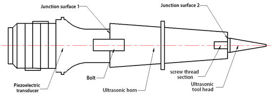
Figure 1.
Assembly structure and junction surface distribution of acoustic vibration components.
In this paper, the diameter of the output end of the piezoelectric transducer is 38 mm, and the connection parameters of the junction surface are shown in Table 1.

Table 1.
Connection parameters of each junction surface.
2.2. Assembly Parameter Analysis of the Junction Surface of Acoustic Vibration Components
The preload on the junction surface was imposed by a torque wrench. The junction surface of the piezoelectric transducer and the ultrasonic horn was affected not only by the vertical preload force but also by the friction force. The junction surface had relative movement during the screwing process, as shown in Figure 2. With increased torsion force, abrasive wear occurred on the junction surface with large roughness. The surface was scratched. The gap of the junction surface increased, and the transmission efficiency of ultrasonic waves was reduced. The transducer could not be reused and reduced the service life. The junction surface needed to improve the surface roughness.
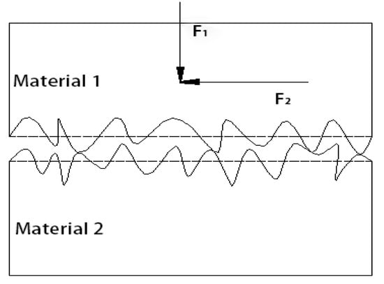
Figure 2.
Actual force diagram when the junction surface was connected.
- (1)
- Preload Calculation
A torque wrench controlled the preload force of the ultrasonic vibration component’s connecting screws. The torque range of the torque wrench used in this paper was 0–60 N·m with a resolution of 0.1 N·m.
The size of the connection screw on the transducer and the ultrasonic horn was: 1/2–20. The size of the connection screw on the ultrasonic horn and the ultrasonic tool was: 3/8–24.
The preload torque of the screw could be divided into two parts [16]: the frictional resistance torque between the thread pairs and the frictional resistance torque between the junction surfaces , which was in Equation (1).
Frictional resistance torque between thread pairs was in Equation (2):
where was the pre-tightening force; was pitch diameter of thread, ; was lead angle of thread; was equivalent friction angle of thread pair, .
The frictional resistance torque between two junction surfaces was in Equation (2)
where was inner diameter of junction surface, was outer diameter of junction surface, and was friction coefficient between junction surfaces.
Substitute Equations (2) and (3) into (1), we got Equation (4)
It can be seen from Equation (4) that the preload force of the screw is not only related to the preload torque but also the area and friction coefficient of the junction surface. When preload torque was the same, the larger the area and friction coefficient of the junction surface were and the smaller the preload force of the bolt was and vice versa. Therefore, the key parameters of ultrasonic vibration assembly were preload torque and friction coefficient.
To study the influence of preload of the junction surface on the performance parameters of ultrasonic acoustic components, ultrasonic vibration components with low surface roughness were required. The smaller the surface roughness was, the lower the friction coefficient of the junction surface was. Lubricants were used to further reduce the friction coefficient on the junction surface.
Substituting the key parameters shown in Table 1 into Equation (4), we obtained the relationship between preload torque and preload force, as shown in Table 2.

Table 2.
Relationship between preload torque and preload force.
- (2)
- Calculation of maximum preload torque
Although increasing the bolt preload can improve the transmission efficiency of ultrasonic waves at the junction surface, excessive preload would damage the screw. Therefore, Equation (5) is used for strength verification.
where was the cross-sectional area of the screw; was the allowable tensile stress.
The size of the transducer screws was 1/2–20, the grade was 12.9, the material was titanium alloy, the tensile strength was 1200 MPa, and the yield strength was 1080 MPa. Safety factor was two. Therefore, the allowable tensile stress was 540 MPa.
The data of tool head screws were size 3/8–24, the grade was 8.9, the material was high speed steel, the tensile strength was 800 MPa, and the yield strength was 720 MPa. Safety factor was two. Therefore, the allowable tensile stress was 360 MPa.
In substituting the above data into Equation (5), it was obtained that the maximum preload torque of ultrasonic horn screw was 150 N·m, and the maximum preload torque of tool screw was 40 N·m.
This calculation method of preload force and preload torque was greatly affected by the friction coefficient, and there was an error in the calculation of preload force. Therefore, it could only be used to estimate the strength of preload force. The surface quality guaranteed by manufacturing technology, this paper considered the influence of friction coefficient qualitatively on the static performance of acoustic vibration components through the lubrication junction surface. We studied the influence of preload torque quantitatively on the static performance of acoustic vibration components.
3. Acoustics Performance Parameters and Measuring Devices for Acoustic Components Performance Parameter
3.1. Static Acoustics Performance Parameters
The performance parameters of acoustic vibration components included resonant frequency, impedance characteristic parameters, quality factor, and frequency bandwidth.
The resonant frequency was the frequency at which the acoustic vibration component generates mechanical resonance, equal to or close to the working frequency of the ultrasonic power supply. If the resonant frequency of the acoustic vibration component deviated greatly from the working frequency provided by the ultrasonic power supply, the ultrasonic power supply would not track the resonant point well or could not track the resonant point. This would cause the acoustic vibration component to fail to vibrate and the vibration amplitude would not be enough to meet the amplitude requirements.
Impedance characteristic parameters were key factors for matching the impedance characteristics between ultrasonic power supply and acoustic vibration components. These mainly included free capacitance and dynamic resistance. The free capacitance was mainly generated by the vibration of piezoelectric materials. When the transducer of the acoustic vibration component was determined, the free capacitance was determined with little change, so the dynamic resistance was the main parameter considered for impedance characteristics.
A quality factor was a scalar reflecting the damping of the acoustic vibration components. It represented the energy loss in acoustic vibration components. The larger the value was, the smaller the energy loss was. The smaller the damping, the higher efficiency of ultrasonic transmission was in acoustic vibration components. However, its value should not be too high. Excessive quality factors would narrow the frequency bandwidth and reduce the stability of acoustic vibration components. Therefore, the value of the quality factor of the acoustic vibration component should be moderate, for example, 1000–3000.
Frequency bandwidth reflected the working stability of the acoustic vibration components. The wider the frequency band, the stronger the adaptability and stability of the acoustic vibration components were. The narrower the frequency band, the weaker adaptability and stability, leading to a higher requirement for the tracking ability of the ultrasonic power supply. However, the frequency of acoustic vibration components would change in actual work, so the frequency bandwidth of acoustic vibration components should not be too small.
3.2. Dynamic Test Performance Parameters
In this paper, the dynamic parameter performance refers to the working performance index required by the design of acoustic vibration components under no-load conditions. It included amplitude, frequency drift, temperature, and power.
Amplitude was an important parameter in ultrasonic machining applications, and different amplitude was required for different applications. The amplitude of the acoustic vibration components decreased with the increased working time. Excessive frequency drift would lead to the mismatch of ultrasonic power supply in operation. The temperature of the ultrasonic transducer in the acoustic vibration component rises under the condition of high-frequency vibration, and the rise in temperature changes the performance parameters of the acoustic vibration component. The lower temperature of the acoustic vibration component was in the same amplitude; the acoustic vibration component was better. Power reflected the amount of energy required by the acoustic vibration components during operation, that was, the energy utilization rate in the same working conditions. The smaller power was in the same amplitude; the acoustic vibration component was better.
3.3. Measuring Device for Performance Parameters of Acoustic Vibration Components
The static performance parameters were measured by an ultrasonic impedance analyzer. The PV70A ultrasonic impedance analyzer of Beijing Confederation Times Electronic Technology Co., Ltd. was used in this test, as shown in Figure 3. Through the test of acoustic vibration components, key static performance parameters such as resonant frequency and dynamic resistance of acoustic vibration components could be obtained. These were the key factors in estimating the reliability of acoustic vibration components and whether they could match well with matching circuits.

Figure 3.
PV70A Ultrasonic Impedance Analyzer.
A dynamic performance test system for acoustic vibration components was set up, as shown in Figure 4.
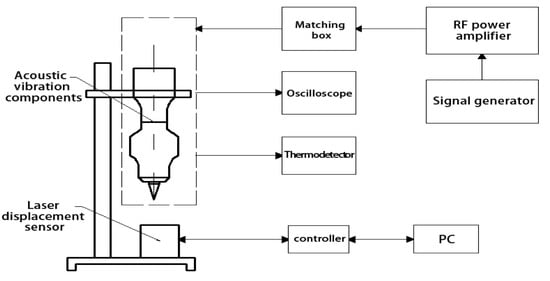
Figure 4.
Frame Diagram of Acoustic Vibration Component Dynamic Performance Test System.
The dynamic performance experiment set of acoustic vibration components is shown in Figure 5 and is mainly composed of test modules for frequency drift, amplitude, power, and temperature. The frequency drift test module made the acoustic vibration components reach the best state by adjusting the signal frequency generated by the signal generator (AFG3022C, Tektronix, Beaverton, OR, USA) and collected the frequency value of the signal generator, and obtained the frequency drift. The amplitude test module controlled the laser displacement sensor (LK-G5000, KEYENC, Osaka, Japan) through a PC to measure the amplitude. The power test module used the voltage probe and current probe of the oscilloscope (MDO3014, Tektronix, Beaverton, OR, USA) to collect the voltage, current, phase angle, and other signals of the acoustic vibration component in real time to measure the ultrasonic power. The temperature of the transducer was the highest temperature in the component when the acoustic vibration component was working. The infrared imager (E50, FLIR, Portland, OR, USA) was used to measure the temperature of the transducer.
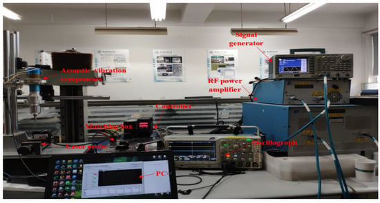
Figure 5.
Acoustic Vibration Component Dynamic Performance Experiment Set.
4. Analysis of the Influence of Assembly Parameters on the Static Performance of Acoustic Vibration Components
In this section, preload torque was applied with a torque wrench to study the influence of preload torque on the static performance of acoustic vibration components quantitatively. The influence of friction coefficient on the static performance of acoustic vibration components was studied by whether there was lubricant on the junction surface qualitatively. The static performance parameters were measured by an ultrasonic impedance analyzer. To avoid the mutual interference of different junction surface assembly parameters, no tool head (straight blade knife) was installed to obtain the optimal horn junction surface assembly parameters when studying the influence of ultrasonic horn junction surface assembly parameters on static performance parameters. Then, the tool was installed to study the influence of the assembly parameters of the junction surface at the tool head on the static performance of the ultrasonic acoustic system.
4.1. Analysis of the Influence of the Assembly Parameters of the Junction Surface at the Ultrasonic Horn on the Static Performance Parameters
According to the calculation in Section 2.2, the upper limit of the preload torque of the connecting screws of Grade 12.9 1/2–20 was 150 N·m. Applied 0–60 N·m of the ultrasonic horn preload torque to analyze the influence of the preloading force on the static performance of the acoustic vibration component. The influence of lubricant was studied by whether vaseline oil was used between the junction surfaces. The experimental results of the influence of the assembly parameters of the junction surface at the ultrasonic horn on the static performance parameters, shown in Figure 6.
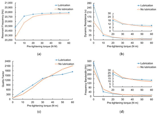
Figure 6.
Influence of assembly parameters of junction surface at ultrasonic horn on static performance parameters. (a) Influence of pre-tightening torque of ultrasonic horn junction surface on resonance frequency. (b) Influence of pre-tightening torque of ultrasonic horn junction surface on dynamic resistance. (c) Influence of pre-tightening torque of ultrasonic horn junction surface on quality factor. (d) Influence of pre-tightening torque of ultrasonic horn junction surface on frequency bandwidth.
4.1.1. Analysis of Influence of Preloading Torque of Ultrasonic Horn on Static Performance Parameters
It can be seen from Figure 6a that the resonant frequency changes significantly with the change in the preloading torque of the ultrasonic horn. In the 0–20 N·m range, the resonant frequency rose rapidly, reaching a variation of 300–500 Hz. At 20–30 N·m, the rise of resonance frequency slowed down. After 30 N·m, the change of resonance frequency tended to stabilize with the increase of preloading torque, and the influence of preloading torque on resonance frequency decreased.
It can be seen from Figure 6b that with the change of preloading torque of the ultrasonic horn, the dynamic resistance changes significantly, and the initial value reaches hundreds of ohms. The dynamic resistance dropped rapidly in the 0–20 N·m range and slowed down in the 20–30 N·m range. After 30 N·m, the dynamic resistance changed slowly.
It can be seen from Figure 6c that with the change of preload torque of the ultrasonic horn, the quality factor changed significantly from tens to about 2000 and increased with the increase of preload torque.
It can be seen from Figure 6d that with the change of preloading torque of ultrasonic horn, the frequency bandwidth changes significantly, from hundreds to about ten. In the preload torque 0–20 N·m range, the frequency bandwidth decreases rapidly. In the 20–30 N·m range, the frequency bandwidth changes decreased, and the trend slowed down. After 30 N·m, the frequency bandwidth change tended to be stable.
4.1.2. Analysis of the Influence of Ultrasonic Horn Lubrication State on Static Performance Parameters
It can be seen from Figure 6a that at the beginning when there is lubrication between the junction surfaces, the resonance frequency is higher than that without lubrication. With the increase of the preload torque, the difference between the resonance frequency with lubrication and without lubrication gradually decreases and tends to be stable. After the resonance frequency is stable, the resonance frequency with lubrication is 20–30 Hz higher than without lubrication.
It can be seen from Figure 6b that the initial value of the dynamic resistance in the lubricated state is smaller than that in the non-lubricated state. With the increase of preload torque, the difference in the dynamic resistance is only a few ohms after the preload torque reaches 20 N·m. After the preload torque reaches 30 N·m, the dynamic resistance in the non-lubricated state is smaller than that in the lubricated state.
It can be seen from Figure 6c that the initial value of the quality factor is the same. The change of the quality factor with lubrication after 40 N·m tends to be gentle, and the quality factor with lubrication after 40 N·m is smaller than that without lubrication.
It can be seen from Figure 6d that the initial value of frequency bandwidth is larger in the lubricated state and tends to be stable earlier in the lubricated state. The bandwidth value is slightly larger than that in the non-lubricated state, and the difference is not significant, only 2 Hz.
From the analysis of static performance parameters, it could be seen that for the assembly parameters of the junction surface at the ultrasonic horn, the change of preload torque had a greater impact on the static performance parameters of the acoustic vibration component. In comparison, the lubrication state had a smaller impact on them, but it could not be ignored. Under the same stable state, higher resonance frequency, slightly larger dynamic resistance and frequency bandwidth, and smaller quality factor could be obtained with lubrication between the junction surfaces. The junction surface between the ultrasonic horn and the transducer had large friction, which would cause corresponding wear, as shown in Figure 7, reducing its service life and reusability. Based on the analysis of the static performance parameters, to obtain relatively stable static performance parameters, the quality factor should not be too high. Additionally, the frequency bandwidth should not be too small, the preload torque should be 30–50 N·m, and lubricant should be added between the junction surfaces.
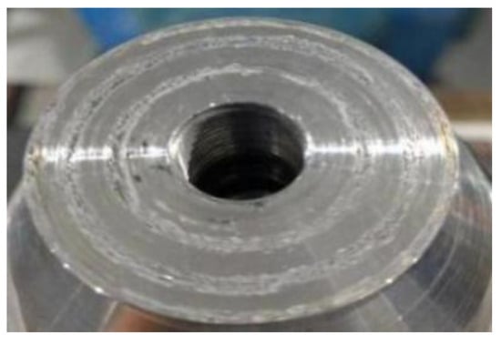
Figure 7.
Face of ultrasonic horn without lubrication.
4.2. Analysis of the Influence of the Assembly Parameters of the Tool (Straight Edge Knife) Junction Surface on the Static Performance
According to the calculation in Section 2.2, the upper limit of the preloading torque of the 3/8–24 screw was 40 N·m. The junction surface of the ultrasonic horn and the transducer was assembled with the assembly parameters determined in the previous section. Applied 0–30 N·m preload torque on the connecting bolt of the tool to analyze the static performance parameters of the ultrasonic horn with the tool (straight blade knife). The influence of lubricant on the static performance parameters was studied by whether Vaseline oil was applied or not between the junction surfaces. Figure 8 shows the experimental results of static performance parameters of the ultrasonic horn with the tool (straight-edge knife).
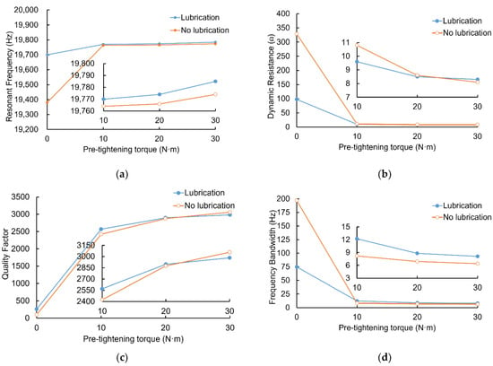
Figure 8.
Influence of the tool (straight edge knife) assembly parameters on static performance parameters. (a) Influence of pre-tightening torque of the tool junction surface on resonance frequency. (b) Influence of pre-tightening torque of the tool junction surface on dynamic resistance. (c) Influence of pre-tightening torque of the tool junction surface on quality factor. (d) Influence of pre-tightening torque of the tool junction surface on frequency bandwidth.
4.2.1. Analysis of the Influence of the Preloading Torque on the Static Performance Parameters of the Tool (Straight Edge Knife) Junction Surface
It can be seen from Figure 8a that with the increase of preloading torque, the resonant frequency changes obviously within the range of 0–10 N·m of preloading torque. Currently, the resonant frequency value rises rapidly. After 20 N·m, the resonant frequency gradually becomes stable.
It can be seen from Figure 8b that the dynamic resistance changes obviously within the range of 0–10 N·m of the preloading torque. At this time, the dynamic resistance value drops rapidly, and the trend slows down and gradually becomes stable after 20 N·m;
It can be seen from Figure 8c that the quality factor changes obviously within the range of 0–10 N·m of the preload torque, rising from a few hundred to about 2500, then slowing down and gradually becoming stable after 20 N·m;
It can be seen from Figure 8d that the frequency bandwidth changes obviously within the range of 0–10 N·m of preloading torque. The frequency bandwidth drops rapidly, and the trend slows down and gradually becomes stable after 20 N·m.
4.2.2. Analysis of the Influence of Lubrication on the Static Performance Parameters of the Tool (Straight Edge Knife) Junction Surface
It can be seen from Figure 8a that the initial value of the resonant frequency with lubrication is larger than that of no lubrication. With the increase of the preload torque, the difference of the resonant frequency gradually decreases and tends to be stable after 20 N·m. The resonant frequency difference is less than 10 Hz. When it is stable, the resonant frequency value with lubrication is slightly larger.
It can be seen from Figure 8b that the difference between the initial values of dynamic resistance is large. With the increase of preload torque, the dynamic resistance difference gradually decreases and tends to be stable after 20 N·m, and the dynamic resistance difference is less than 1 Ω. When it is stable, the dynamic resistance value with lubrication is slightly higher.
It can be seen from Figure 8c that there is little difference with the quality factors, whether the surface is lubricated or not has little influence on the quality factors, and the value of quality factors with lubrication is slightly smaller when it is stable.
It can be seen from Figure 8d that the initial value of frequency bandwidth has a large difference. After 20 N·m, it is fairly constant in lubrication and non-lubrication with a difference of less than 1 Hz. When it is stable, the frequency bandwidth with lubrication is slightly larger.
Regarding the above analysis of static performance parameters, for the assembly parameters of the junction surface at the tool (straight edge knife), the preload torque, and the lubrication state had a greater impact on the static performance parameters of the vibration components when the preload torque was within the range of 0–10 N·m. When the preload torque was greater than 20 N·m, the influence was small. In a stable state, higher resonance frequency, slightly larger dynamic resistance and frequency bandwidth, and smaller quality factor can be obtained with lubrication between the junction surfaces. The preload torque should be 20–30 N·m, and lubricant should be added between the junction surfaces.
5. Analysis of the Influence of Assembly Parameters on the Dynamic Performance of acoustic Vibration Components
The influence of the assembly parameters of the junction surface on the static performance parameters of the ultrasonic horn was analyzed, and the optimal assembly parameters under the static performance was determined. Based on the optimal assembly parameters determined by static performance parameters, this section studied the influence law of the assembly parameters on the dynamic performance parameters of the ultrasonic horn under a certain output amplitude and determined the final optimal assembly parameters.
In order to avoid mutual interference of different junction surfaces when studying the assembly parameters at the ultrasonic horn, the tool (straight blade knife) was not installed to obtain the optimal assembly parameters at the junction surface of the ultrasonic horn. Then the tool was installed to study the influence of the assembly parameters of the junction surface at the tool on the dynamic performance of the ultrasonic acoustic system.
5.1. Analysis of the Influence of Assembly Parameters at the Junction Surface of Ultrasonic Horn on the Dynamic Performance of Acoustic Vibration Components
The ultrasonic transducer was connected to the ultrasonic horn. The end amplitude of the ultrasonic horn was fixed to 15 μm. During the running time of 0–150 min, the influence of the assembly parameters at the junction surface of the ultrasonic horn on the frequency drift, temperature rise, and power of the acoustic vibration component was tested without a tool head. It could conclude from Section 4.1 that the friction coefficient of the two junction surfaces was high without lubrication when the preload torque was large. The junction surfaces would be worn. The service life was reduced. Therefore, the preload torque was only studied in the range of 0–60 N·m with the lubrication junction surfaces.
5.1.1. Analysis of the Influence of the Preload Torque of the Junction Surface at the Ultrasonic Horn on the Frequency Drift of the Acoustic Vibration Component
During the running time of 0–150 min, the resonance frequency of the ultrasonic horn under different assembly preload torques was measured using the dynamic performance parameter measurement system. According to the experimental data, the influence of the preload torque at the junction surface of the ultrasonic horn between 10–60 N·m on the resonant frequency of the acoustic vibration component (without tool head) was drawn, as shown in Figure 9.
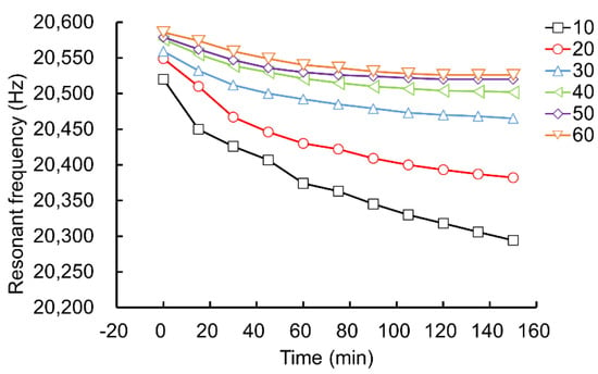
Figure 9.
Effect of Preload Torque of Ultrasonic Horn on Resonance Frequency Drift of Acoustic Vibration Component.
It can be seen from Figure 9 that when the output end of the ultrasonic horn maintains an amplitude of 15 μm, the resonant frequency decreases gradually with the increase of working time. With the increase of preload torque, the resonant frequency drift of acoustic vibration components tends to be stable, and the time to reach the stable state decreases. At 50 N·m, the resonant frequency drift reaches the minimum, only about 60 Hz.
5.1.2. Analysis of the Influence of the Preloading Torque of the Junction Surface at the Ultrasonic Horn on the Temperature of the Acoustic Vibration Component
During the running time of 0–150 min, the infrared imager was used to measure the temperature of the acoustic vibration component with different assembly preload torques on the junction surface of the ultrasonic horn. The infrared temperature measurement experimental device is shown in Figure 10. The temperature distribution of the transducer is shown in Figure 11.
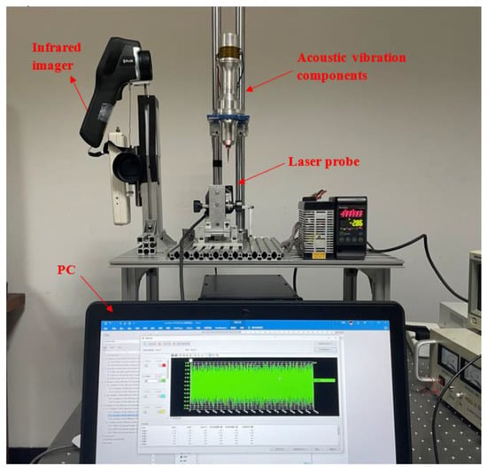
Figure 10.
Infrared Temperature Measurement Experimental Device.
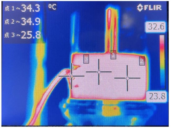
Figure 11.
Temperature Distribution of the Transducer.
According to the experimental data, the influence of the preloading torque of the junction surface at the ultrasonic horn on the temperature of the acoustic vibration component is plotted, as shown in Figure 12.
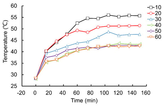
Figure 12.
Effect of Preload Torque of Ultrasonic Horn on Temperature of Acoustic Vibration Component.
It can be seen from Figure 12 that when the amplitude of the output end of the ultrasonic horn maintains the amplitude of 15um, the transducer temperature gradually rises with the increase of time and tends to be stable. The smaller the preload torque, the more pronounced the temperature rise, up to 55 °C. When the preload torque reaches 40 N·m, the temperature is saturated, only 42–43 °C.
5.1.3. Analysis of the Influence of the Preload Torque of the Junction Surface at the Ultrasonic Horn on the Power of the Acoustic Vibration Component
During the running time of 0–150 min, the dynamic performance parameter measurement system is used to measure the power data with different assembly preload torques of the junction surface at the ultrasonic horn.
According to the experimental data, the influence of the preloading torque of the junction surface at the ultrasonic horn on the power of the acoustic vibration component (Power measured at the transducer end) is plotted, as shown in Figure 13.
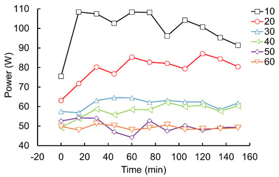
Figure 13.
Effect of preload torque at the Junction Surface of Ultrasonic Horn on the Power of Acoustic Vibration Component.
It can be seen from Figure 13 that when the amplitude of the output end of the ultrasonic horn maintains the amplitude of 15 μm, the power required by the acoustic vibration component increases with time. The power is unstable when the preload torque is 10–20 N·m. The power is relatively stable when the preload torque is 30–60 N·m. The larger the preload torque is, the smaller the power required. At 50–60 N·m, the power is stable.
In sum, the best assembly parameter of the junction surface at the ultrasonic horn was to set the preload torque to about 50 N·m and added lubricant between the junction surfaces.
5.2. Analysis of the Influence of the Assembly Parameters of the Tool (Straight Edge Knife) Junction Surface on the Dynamic Performance of the Acoustic Vibration Component
A straight-edge knife with a length of 37 mm was assembled on the end of the ultrasonic transducer and ultrasonic horn. The amplitude of the end of the straight-edge knife tip was fixed at 30 μm. During the running time of 0–150 min, the influence of the assembly parameters of the junction surface with straight-edge knife on the frequency drift, temperature, and power of the acoustic vibration component was studied. To avoid wear on the junction surface, the state with lubrication conditions was selected for the experiment.
5.2.1. Effect of Preload Torque of Junction Surface at Straight Edge Knife on Frequency Drift of Acoustic Vibration Component
According to the experimental data, the influence of the preload torque of the junction surface at the straight-edge knife on the frequency drift of the acoustic vibration component is plotted, as shown in Figure 14.
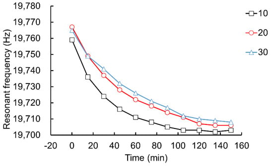
Figure 14.
Effect of preload torque of Junction Surface at Straight Edge Knife on Frequency Drift of Acoustic Vibration Component.
It can be seen from Figure 14 that the tool tip amplitude remained at 30 μm, the resonant frequency gradually decreased with the increase of working time and tended to be stable. Later, the change of the preloading torque had little effect on the drift of its resonant frequency, and it remained nearly stable at about 50 Hz.
5.2.2. Effect of Preload Torque of Junction Surface at Straight Edge Knife on Temperature of Acoustic Vibration Component
According to the experimental data, the influence of the preload torque of the junction surface at the straight-edge knife on the temperature of the acoustic vibration component is plotted, as shown in Figure 15.
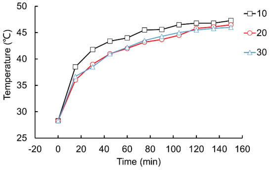
Figure 15.
Effect of preload torque of Junction Surface at Straight Edge Knife on Temperature of Acoustic Vibration Component.
It can be seen from Figure 15 that the tooltip amplitude remained at 30 μm; the temperature gradually rises with the increase in working time and tends to be stable. After a certain operating time, the preload torque has little influence on the temperature, and the temperature remains constant at 46 °C. When the preload torque is near 10 N·m, the temperature rise speed is slightly faster.
5.2.3. Effect of preload torque of junction surface at straight edge knife on power of acoustic vibration component
According to the experimental data, the influence of the preload torque of the junction surface at the straight-edge knife on the power of the acoustic vibration component (Power measured at the transducer end) is plotted, as shown in Figure 16.
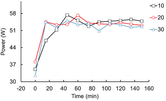
Figure 16.
Effect of preload torque of Junction Surface at Straight Edge Knife on Power of Acoustic Vibration Component.
It can be seen from Figure 16 that the tooltip amplitude remained at 30 μm, and the power required by the acoustic vibration component rises rapidly over time and remains stable at about 50 w.
To sum up, the preload torque had little influence on the dynamic performance parameters of the tool (straight-edge knife). Considering the cutting stiffness of the tool, the best assembly parameters of the junction surface at the tool (straight-edge knife), such as the preload torque, were set to about 25 N·m, and lubricant was added between the junction surfaces.
Combined with the analysis of static and dynamic performance parameters by preload torque, the assembly parameters of the junction surface at the ultrasonic horn were set as follows: lubricated, 50 N·m preload torque. The assembly parameters of the junction surface of the tool (straight-edge knife) were set as follows: lubricated, 25 N·m preload torque. The same method can also be used for other types of tool heads and transducers to find the best assembly parameters.
6. Conclusions
By comparing and analyzing the influence of assembly parameters at the junction surface of ultrasonic horn and tool (straight edge knife) on static and dynamic performance parameters, it is found that:
- (1)
- The increase of preload torque can improve the static performance of acoustic vibration components, and increase the resonant frequency, reduce the dynamic resistance, increase the quality factor and the frequency bandwidth. The influence of the preloading torque of the junction surface at the ultrasonic horn on the performance parameters of the ultrasonic horn is far greater than that of the junction surface at the tool (straight-edge knife). The reason is that the area of the two junction surfaces is different. The larger the area of the junction surface, the greater the influence of the preloading torque on the static performance.
- (2)
- The lubricant can effectively avoid the wear of the junction surface and improve the service life. In a stable state, the ultrasonic acoustic components with lubrication have higher resonance frequency, slightly higher dynamic resistance, slightly lower quality factor, and slightly larger frequency bandwidth than those without lubrication.
By comparing the assembly parameters at the junction surface of the ultrasonic horn and the tool (straight-edge knife) on the dynamic performance parameters, it is found that:
- (1)
- With the increase of preload torque, the resonant frequency drift of acoustic vibration components tends to be stable, and the time reaches the stable state decreases.
- (2)
- When the preload torque at the junction surface of the ultrasonic horn exceeds 40 N·m, the temperature rise is basically unchanged. The preload torque of the junction surface at the straight-edge knife has little influence on the temperature rise.
- (3)
- The power required by acoustic vibration components rises and fluctuates with time. The larger the preload torque, the smaller the power required. When the preload torque at the junction surface of the ultrasonic horn is 50–60 N·m, the power is basically stable. The preload torque at the junction surface of straight-edge knife has little influence on the power.
Combining the static and dynamic performance parameters, the assembly parameters of the junction surface at the ultrasonic horn are: lubricated, 50 N·m preload torque. The assembly parameters of the junction surface at the straight edge knife are: lubricated, 25 N·m preload torque. The same method can also be used for other types of tool heads and transducers to find the best assembly parameters. The determination of the optimal assembly parameters improves the ultrasonic transmission efficiency and the working stability of the acoustic vibration component.
Author Contributions
Conceptualization, H.Y., X.H. (Xiangkui Huang), X.H. (Xiaoping Hu) and B.Y.; Data curation, X.H. (Xiaoping Hu) and B.Y.; Investigation, H.Y. and X.H. (Xiangkui Huang); Methodology, H.Y. and X.H. (Xiangkui Huang); Supervision, X.H. (Xiaoping Hu) and B.Y.; Validation, H.Y.; Visualization, H.Y.; Writing—original draft, H.Y.; Writing—review and editing, H.Y. and X.H. (Xiangkui Huang). All authors have read and agreed to the published version of the manuscript.
Funding
This research was funded by [the National Natural Science Foundation of China] grant number [No. 51975173], [Zhejiang Public Welfare Technology Research Program/Industry Project] grant number [LGG21E050010]. And The APC was funded by [the National Natural Science Foundation of China] grant number [No. 51975173], [Zhejiang Public Welfare Technology Research Program/Industry Project] grant number [LGG21E050010].
Institutional Review Board Statement
Not applicable.
Informed Consent Statement
Not applicable.
Data Availability Statement
The data presented in this study are available on request from the corresponding author. The data are not publicly available due to privacy.
Acknowledgments
This research was supported by the National Natural Science Foundation of China (No. 51975173), Zhejiang Public Welfare Technology Research Program/Industry Project (LGG21E050010).
Conflicts of Interest
The authors declare no conflict of interest.
References
- Parrini, L. New methodology for the design of advanced ultrasonic transducers for welding devices. In Proceedings of the 2000 IEEE Ultrasonics Symposium. Proceedings. An International Symposium (Cat. No. 00CH37121), San Juan, PR, USA, 22–25 October 2000; pp. 699–704. [Google Scholar]
- Zhang, Y.; Zhu, D.; Zhang, S.; Qian, Y. Research on vibration transfer characteristics of the bolt connection structure. J. Fail. Anal. Prev. 2017, 17, 68–78. [Google Scholar] [CrossRef]
- Han, L.; Zhong, J.; Gao, G. Effect of tightening torque on transducer dynamics and bond strength in wire bonding. Sens. Actuators A Phys. 2008, 141, 695–702. [Google Scholar] [CrossRef]
- Li, Z.; Wu, X.; Zhili, L. Study of prepress force on piezoelectric transducer of wire bonding. In Proceedings of the 2008 International Conference on Electronic Packaging Technology & High Density Packaging, Shanghai, China, 28–31 July 2008. [Google Scholar]
- Arnold, F.J.; Muhlen, S.S. The resonance frequencies on mechanically pre-stressed ultrasonic piezotransducers. Ultrasonics 2001, 39, 1–5. [Google Scholar] [CrossRef]
- Arnold, F.J.; Mühlen, S.S. The mechanical pre-stressing in ultrasonic piezotransducers. Ultrasonics 2001, 39, 7–11. [Google Scholar] [CrossRef]
- Deangelis, D.A.; Schulze, G.W.; Wong, K.S. Optimizing piezoelectric stack preload bolts in ultrasonic transducers. Phys. Procedia 2015, 63, 11–20. [Google Scholar] [CrossRef]
- Qiao, J.; Wang, F. Effect of tightening torque on the frequency of the sandwich piezoelectric ceramic transducer vibrator. In Proceedings of the 2010 11th International Conference on Electronic Packaging Technology & High Density Packaging, Xi’an, China, 16–19 August 2010. [Google Scholar]
- Zhou, C.; Pi, J. The Pretightening Force Effect of the Sandwiched Piezoelectric Ceramic Flexural Transducer Vibration Characteristics. Mach. Des. Manuf. 2013, 5, 105–108. [Google Scholar]
- Jiang, X.; Wang, K.; Zhang, D. Determining the optimal pre-tightening force of a sandwich transducer by measuring resonance resistance. Appl. Acoust. 2017, 118, 8–14. [Google Scholar] [CrossRef]
- Zhou, H.; Zhang, J.; Feng, P.; Yu, D.; Wu, Z. Investigation on influence of preload characteristics on output amplitude for giant magnetostrictive ultrasonic vibrator. J. Jilin Univ. Eng. Technol. Ed. 2020, 50, 894–902. [Google Scholar]
- Fu, B.; Li, T.; Xie, Y. Model-based diagnosis for pre-stress of langevin transducers. In Proceedings of the 2009 IEEE Circuits and Systems International Conference on Testing and Diagnosis, Chengdu, China, 28–29 April 2009. [Google Scholar]
- Zhou, H.; Zhang, J.; Feng, P.; Yu, D.; Wu, Z. An amplitude prediction model for a giant magnetostrictive ultrasonic transducer. Ultrasonics 2020, 108, 106017. [Google Scholar] [CrossRef] [PubMed]
- von Arx, M. Novel ultrasonic transducer design for fine-pitch wire bonding. In Proceedings of the IEEE/CPMT/SEMI 28th International Electronics Manufacturing Technology Symposium, San Jose, CA, USA, 16–18 July 2003. [Google Scholar]
- Lesniewski, P. Discrete component equivalent circuit for webster’s horns. Appl. Acoust. 1995, 44, 117124. [Google Scholar] [CrossRef]
- Cheng, D. Handbook of Mechanical Design, 5th ed.; Chemical Industry Press: Beijing, China, 2008; Volume 2, pp. 5–70. ISBN 978-7-122-01409-2. [Google Scholar]
Publisher’s Note: MDPI stays neutral with regard to jurisdictional claims in published maps and institutional affiliations. |
© 2022 by the authors. Licensee MDPI, Basel, Switzerland. This article is an open access article distributed under the terms and conditions of the Creative Commons Attribution (CC BY) license (https://creativecommons.org/licenses/by/4.0/).