Abstract
An endoscopy is a tool that is used to examine the interior of a hollow organ or cavity of the body by inserting directly into the organ. However, intestinal endoscopy is not friendly to patients due to discomfort, and it can easily cause intestinal damage or even perforation due to the use of the rigid materials of the endoscopy. Here, we provide an earthworm-based intestinal soft robot equipped with a gripper for application on intestinal exams or surgery. The intestinal soft robot is composed of a frontal radial actuator, a central axial actuator, a rear radial actuator and a gripper. The first three actuators drive the robot to move freely in some specific pipes by altering its own deformation, and the gripper, fixed at the end of the frontal radial actuator, is used to pick up “foreign bodies” into and out of the pipes for the purpose of intestinal applications. The different experiments validated that the intestinal soft robot could move forward and backward autonomously in a rigid pipe, a flexible pipe, and a mucus-containing pipe and could extract objects from these pipes. The ultimate weight that the intestinal soft robot extracts is up to 220 g, and the maximum moving speed is 12.0 cm/min in the rigid pipe. This intestinal soft robot is non-destructive to the operating environment, providing a friendly and novel method for the application of intestinal diseases.
1. Introduction
The intestine is the tubular part of the digestive tract that extends from the stomach to the anus and is the main functional area of food digestion and absorption. Various digestive fluids decompose chyme into glucose and amino acids from the foods to be absorbed as nutrients in the intestine. However, many intestinal diseases always cause digestion and absorption disorders and related symptoms such as diarrhea, abdominal pain, abdominal distention and constipation; severe cases may cause ulcerative colitis, Crohn’s disease, and colorectal cancer [1,2]. Clinically, endoscopy is the most common technology for the diagnosis and treatment of intestinal diseases and is also the “gold standard” recognized by the medical community for screening colorectal cancer [3,4]. However, endoscopy is not friendly to patients causing great discomfort and also may damage the intestinal wall and mucosa when invaded into the intestine due to the use of the rigid materials of the endoscopy.
For the aforementioned defects of the endoscopy, a soft robot is an excellent choice for the diagnosis and treatment of intestinal diseases because of its high flexibility and friendly interaction with patients. Soft robots are defined as systems that are capable of autonomous behavior by adopting hyperelastic materials with Young’s modulus in the range of that of soft biological materials for the main body and moving parts [5,6], such as polymer, silicone rubber or other flexible materials [7,8]. Unlike rigid bodies, soft robots are considered to have infinite degrees of freedom because they can deform arbitrarily [9,10] and are suitable for various complex environments and can interact with humans safely [11,12]. Therefore, soft robots are now widely used in human–machine interaction, wearable devices, and especially in the field of medical treatment. In addition, many studies on the applications of soft robots for the examination and treatment of intestinal diseases were achieved. For example, Chan J. et al. proposed a bio-inspired snail-like soft robot, which used the pedal wave observed in the snail movement and the non-Newtonian characteristics of interstitial mucus to translate in the gastrointestinal tract [13]; Heung H. et al. introduced a soft pneumatic earthworm-like robot which can crawl actively in a tubular environment, and by integrating a wireless camera, it can also achieve intrinsically safe gastrointestinal examination [14]; Manfredi L. et al. reported a soft pneumatic inchworm-like micro robot for colonoscopy. The robot is composed of two balloons, which are connected by a soft pneumatic actuator with three degrees of freedom. This design reduces the pressure exerted on the inner wall of the colon, thereby reducing the pain and discomfort during the operation [15]; Yan G. et al. proposed a wireless micro-robot system for an endoscope that is able to move autonomously in a rubber tube and the intestine of the pig through earthworm movement [16]. This micro-robot is able to move forward and backward at different speeds and can also stay at any location of the intestines for the exam. The above designs have a great role in promoting the development of intestinal examination and treatment by soft robots. However, the current researches are mainly to break through the problem of controlled movement of soft robots in the intestinal or intestinal-like environments while realizing other auxiliary functions, including surgery and removal of diseased tissue, are not investigated.
In this paper, we propose a novel pneumatic earthworm-like intestinal soft robot equipped with a soft gripper. The intestinal soft robot is designed based on an earthworm-like soft robot, which can move in a small pipe space. The earthworm-like soft robot has been excavated for intestinal applications, but the previous researches are almost only limited to realizing the controlled movement in the intestine or intestine-like environments [13,14,15,16]. Here, the soft robot is further developed by equipping a soft gripper, which is used for the function of drug load or surgery on the basis of the mobile function, for further promoting the application of the soft robot in the treatment of intestinal diseases. For the first time, this paper proposes the intestinal soft robot that uses an earthworm-like robot as the movement carrier and uses a gripper as an intestinal examination tool to propose a novel and potential method to detect or treat intestinal diseases via the carrier.
2. Design and Fabrication of the Intestinal Soft Robot
2.1. Design of the Soft Robot
Inspired by the movement mechanism of earthworms [17,18,19], the intestinal soft robot in this paper adopts an earthworm-like body structure to achieve controllable and non-destructive movement in the intestine, as shown in Figure 1. The intestinal soft robot is composed of a frontal radial actuator, a central axial actuator, a rear radial actuator and a soft gripper. The gripper is assembled to the end of the frontal radial actuator. The central axial actuator is limited to the radial expansion by the O-ring. While due to the small axial length, the radial actuator will expand radially after inflation, and the axial expansion can be ignored. By alternately inflating and deflating the three actuators, the soft robots creep into the intestine.
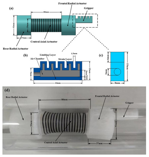
Figure 1.
The structure and size of the intestinal soft robot. (a) The dimensional diagram of the intestinal soft robot. (b) Frontal view of the gripper. (c) Side view of the gripper’s structure. The round hole is used to insert the silicone tube into the air chamber of the gripper. The wall thickness is 2 mm. (d) Prototype of the intestinal soft robot.
As shown in Figure 1a, the diameter and the length of the frontal and rear actuators are 52 mm and 37 mm, respectively; and the diameter and the length of the central axial actuator are 35 mm and 80 mm, respectively. The wall thickness of the three actuators is all 2 mm. The actuators are made of material of Ecoflex-0030 (Smooth-On Inc., Macungie, PA, USA), which is a hyper-elastic material. The gripper structure is shown in Figure 1b,c. It consists of two parts: the strain layer and the limiting layer. To make the gripper bend like a human hand, two materials with different Young’s moduli are used. Ecoflex-0030 is used for the strain layer, and the limiting layer is made of Dragon Skin10 (Smooth-On Inc., USA), which has a higher Young’s modulus than that of the Ecoflex-0030. Moreover, the gripper is 44 mm long, 8 mm wide and 15 mm high. The edges of these two layers are pasted together to form a closed chamber of the gripper driver. After the chamber is inflated and expanded, because of the difference of materials between the strain layer and the limiting layer, the strain layer generates larger deformation to inflate and the limiting layer has very small deformation, which causes the whole gripper to bend towards the strain layer.
2.2. Fabrication of the Intestinal Soft Robot
Based on the above-designed structure of the intestinal soft robot (Figure 1), the fabricating process is demonstrated in the following steps.
- The molds matched with each part of the intestinal soft robot were designed according to the structure shown in Figure 1 using the 3D modeling software (Solidworks) for the fabrication, as shown in Figure 2. Each actuator is axisymmetrically divided into two halves, and the gripper is divided into upper and lower parts to fabricate, respectively. So, the molds are also designed according to this manufacturing method, as shown in Figure 2.
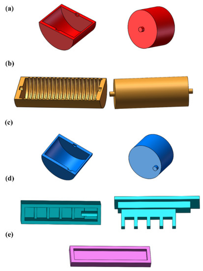 Figure 2. Molds for fabrication of the intestinal soft robot. (a–c) Molds to fabricate the frontal radial actuator, central axial actuator and rear radial actuator, respectively. (d,e) Molds to fabricate the strain layer and the limiting layer of the gripper, respectively.
 - The molds were fabricated with acrylonitrile butadiene styrene (ABS) using a 3D printer (Da Vinci 1.0 AiO, XYZ Inc., Lake Forest, CA, USA). The diameter of the nozzle of the 3D printer is 0.4 mm. The molds were printed with the following printing conditions: hot-end temperature, 220 °C; platform temperature, 90 °C; printing speed 120 mm/s.
- Each actuator and the gripper were fabricated by the corresponding assembled molds. First, part A and part B of the Ecoflex-0030 were mixed (1:1) and stirred thoroughly for 3 min. After that, the mixed silicone rubber was put into the vacuum chamber to defoam for about 7 min to avoid air leakage caused by bubbles on the surface of the formed silicone, and then the silicone rubber was slowly poured into the molds with vaseline release agent treatment on the surface of the molds in advance. Next, the corresponding two parts of each actuator of the intestinal soft robot were glued together via silicone adhesive (Sil-Poxy, Smooth-On Inc., USA) and dried at room temperature for 4 h. The gripper was fabricated with the similar method described above, except that the material of the limiting layer is Dragon skin 10.
3. Control of the Soft Robot
3.1. Movement Gait of the Intestinal Soft Robot
Figure 3 shows an entire motion cycle of the intestinal soft robot body, where Figure 3a is the initial state and Figure 3b–f are five different moving states. At first, the rear radial actuator is anchored to the inner wall of the pipe, and the central axial actuator and frontal radial actuator are relaxed (Figure 3b). Next, the central axial actuator expands and moves forward (Figure 3c). Then, the frontal radial actuator is anchored to the inner wall of the pipe (Figure 3d). After that, the rear radial actuator and the central axial actuator are relaxed (Figure 3e). Later, the rear radial actuator is anchored to the inner wall of the pipe (Figure 3f). Finally, the frontal radial actuator is relaxed, and the intestinal soft robot returns to its initial status. The intestinal soft robot repeats this cycle to keep the robot moving forward. In addition, the intestinal soft robot moves backward if the entire process is reversed.

Figure 3.
A movement cycle of the intestinal soft robot. (a) The initial state of the intestinal soft robot. (b–f) Five statuses during the movement.
3.2. Control System of the Intestinal Soft Robot
The control system of the intestinal soft robot mainly consists of two parts: the controlling part and the driving part. The controlling part includes single chip microcomputer (Arduino Mega 2560, Arduino Inc., Ivrea, Turin, Italy) and relays (OJ-XM1115, OpenJumper Inc., Chengdu, Sichuan, China), while the driving part is composed of two air pumps, two throttled valves (PSA-8, AirTAC Inc., Taiwan, China) and eight solenoid valves. The specific control method is that the relay receives the signal of Arduino and then controls the on/off of solenoid valves and air pumps so as to control the movement of the intestinal soft robot.
The solenoid valve system consists of two-position two-way solenoid valves (2V25-08/DC24V, SMC Inc., Tokyo, Japan) and two-position three-way solenoid valves (3V208NCB/DC24V, SMC Inc., Tokyo, Japan). The combination of the solenoid valves is used to realize three states required for the movement of intestinal soft robot: expansion, contraction and holding. The air pump supplies the gas source for each chamber of the intestinal soft robot, and four two-way valves are connected to the air pump. Air output from the two-way valve is fed into the three-way valve and then flows into the chamber of intestinal soft robot. When both the two-way valve and the three-way valve are energized, the gas will flow into the chamber. Gas will remain in the chamber when the two-way valve is powered off, and the three-way valve is energized. On the contrary, when the two-way valve is energized and the three-way valve is powered off, the gas remaining in the chamber will be discharged from the chamber of intestinal soft robot through the three-way valve. The function of throttle valves is to regulate the flow of gas in the air channel to avoid rupture caused by too high pressure in the chamber of the intestinal soft robot or insufficient expansion caused by too low pressure.
The electro-pneumatic diagram of the system is shown in Supplementary Figure S1, where chambers 1–4 are the chamber of the gripper, the frontal radial actuator, the central axial actuator and the rear radial actuator, respectively. A pump goes through a two-way solenoid valve and a three-way solenoid valve successively to a chamber, and the chamber is inflated and deflated through the linkage control of the two valves; that is, the expansion and contraction control of the actuator is realized. In addition, Supplementary Figure S2 is the circuit diagram of the system. The on–off logic of the solenoid valves controls the expansion or contraction of the corresponding actuator. The on–off of the solenoid valve is controlled by a single-chip computer.
4. Results
4.1. Numerical Simulation of the Soft Robot
The performance of the intestinal soft robot was analyzed by finite element analysis (FEA) to validate its performance. ABAQUS software was selected as the FEA tool in this study. Here, the Hyperelastic material (Ecoflex-0030), used to fabricate the strain layer of the gripper and the other three actuators, is defined by the Yeoh model with the parameters: c10 = 0.11 and c20 = 0.02, while the limiting layer of the gripper was set as Elastic material (Dragon Skin10) with Young’s modulus of 201 kPa and the Poisson’s ratio of 0.49 [20,21].
The results of the numerical simulation and actual experiments on the gripper are shown in Figure 4. Figure 4a is the curved gripper when the inner cavity is loaded with a pressure of 0.45 MPa. It is obvious that the expansion of the gripper in the strain layer is much higher than that of the limiting layer, and the gripper is curved along the limiting layer. The result also illustrates that the designed gripper can grab the target through pneumatically controlled bending. Figure 4b is the curve diagram of the bending angles of the gripper under different loaded pressures by the numerical simulation. The result shows that the bending angle of the gripper is positively correlated with the loaded pressure, and the curved angle can reach 60 degrees at 0.5 MPa. Furthermore, the actual experiments on the bending angles adjusted by different loaded pressures were performed and are shown in Figure 4c. Moreover, in comparison to Figure 4b,c, it is found that the actual bending angle is consistent with the bending angle by numerical simulation.

Figure 4.
Numerical simulation and actual experiment of the gripper. (a) Deformation of the gripper when load is set as 0.45 MPa. (b) Pressure-angle curve of the gripper by numerical simulation. The pressure ranges from 0.05 MPa to 0.5 MPa. (c) Pressure-angle curve of the gripper by actual experiment.
In addition, the results of numerical simulation and actual measurement of the deformation of the radial actuator and the axial actuator are shown in Figure 5. Figure 5a shows the simulation results of the radial actuator being inflated, and it displays that the actuator only expands in the radial direction but has no deformation in the axial direction. In addition, the amplitude of the radial deformation is linear with the input pressure of the corresponding chamber, as shown in Figure 5b. Figure 5c shows the curve between the actual measured radial deformation of the actuator and the input pressure. Compared between Figure 5b,c, the pressure–deformation curves between the numerical simulation and actual measurement are relatively consistent. Figure 5d is the simulation results of the axial actuator being inflated, and it also displays that the actuator only elongated in the axial direction but almost has no deformation in the radial direction. Moreover, Figure 5e,f also demonstrates the pressure–deformation curves between the numerical simulation and actual measurement are relatively consistent.
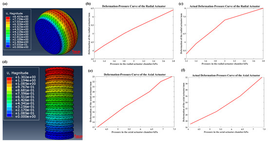
Figure 5.
Numerical simulation and actual experiment of the radial actuator and axial actuator, respectively. (a) Simulation result of the deformation of the radial actuator. (b) Deformation–pressure curve of the radial actuator by numerical simulation. (c) Deformation–pressure curve of the radial actuator by actual experiment. (d) Simulation result of the deformation of the axial actuator. (e) Deformation–pressure curve of the axial actuator by numerical simulation. (f) Deformation–pressure curve of the axial actuator by actual experiment.
4.2. Experiments in a Rigid Pipe
Next, a series of experiments were carried out to verify the functions of the intestinal soft robot. The first experiment, as shown in Figure 6, aimed to demonstrate the ability of the intestinal soft robot to move controllably and extract an object at a fixed point inside a transparent rigid pipe with an inner diameter of 65 mm. The weight of the object (14 mm × 14 mm × 56 mm) to be extracted is 10.6 g.
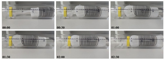
Figure 6.
The intestinal soft robot performs moving and extracting tasks in a transparent rigid tube. (The number represents the running time of the soft robot).
The inflation times of the radial actuator and axial actuator were set as 1.25 s and 2.2 s, respectively, and the holding times were 1.6 s and 1.5 s, respectively, in this experiment. After entering the pipe, the intestinal soft robot moved forward until the target location; then, the gripper was bent and grabbed the object; then, the intestinal soft robot moved backward with the grabbed object and left the pipe. As shown in Figure 6, the intestinal soft robot successfully moved to the front 10 cm and extracted the target, and then returned to the initial position within 3 min. This experiment preliminarily verified that the robot can move controllably in the rigid pipe and extract objects at a fixed point.
Then, the performances of the intestinal soft robot were analyzed and validated by different experiments. At first, the influence of the diameter of the central axial actuator on the maximum moving velocity of the intestinal soft robot was tested. Three intestinal soft robots with different diameters of central axial actuators were manufactured, respectively. Moreover, the diameters are 35 mm, 44 mm and 52 mm, respectively. After extracting the same object with a weight of 9.9 g and a volume of 14 mm × 14 mm × 56 mm, the maximum moving velocity were 6.0, 7.1 and 12.0 cm/min, respectively, as shown in Figure 7a. The result shows that the larger diameters of the central axial actuator produce higher moving speeds.
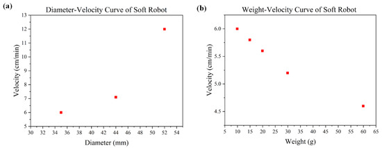
Figure 7.
The moving speeds with different influencing factors. (a) Moving speeds when the diameters of the central axial actuator are set to 35 mm, 44 mm and 52 mm, respectively. (b) Moving speeds when the weight of the object to be extracted ranging from 9.9 g to 59.9 g.
Then, the effect of load on the moving speed was studied. The diameter of the central axial actuator was 35 mm. The weights of objects were set as 9.9, 14.9, 19.9, 29.9 and 59.9 g, respectively, with the same volume of 14 mm × 14 mm × 56 mm. Then, the corresponding velocities were 6.0, 5.8, 5.6, 5.2 and 4.6 cm/min, respectively, also shown in Figure 7b. The result illustrates that increasing the load reduces the movement speed of the intestinal soft robot. In addition, the ultimate weight that the intestinal soft robot can extract was also measured with a tension scale, and that was 220 g.
4.3. Experiment with a Flexible Pipe
The intestine is essentially a flexible tube. Therefore, the performance of the intestinal soft robot was further tested by the experiment in a flexible pipe. The inner diameter of the pipe is 65 mm, and the diameter of the central axial actuator is 52 mm. The weight of the object is 9.9 g. After entering the pipe, the intestinal soft robot moved forward until it reached the target location. Then the gripper was bent and grabbed the object; then, the intestinal soft robot moved backward with the grabbed object and left the pipe. The entire movement process is shown in Figure 8. Moreover, the maximum moving speed was 10.5 cm/min. Although the moving speed was slightly lower in the flexible pipe than that in the rigid pipe, the experiment also proves that the intestinal soft robot has the capability of moving controllably and extracting objects at a fixed point in flexible pipes.
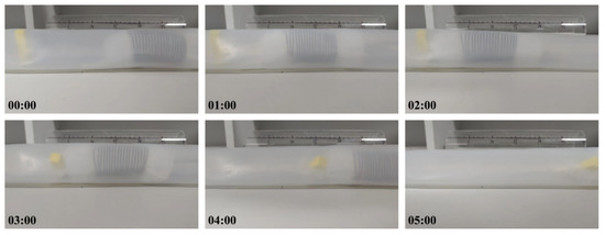
Figure 8.
The intestinal soft robot performs moving and extracting tasks in a flexible tube. (The number represents the running time of the soft robot.)
In addition, the performance of the intestinal soft robot in different pipes was investigated; that is, the intestinal soft robot moved from a flexible pipe to a rigid pipe, and the results are shown in Figure 9. The result shows that the intestinal soft robot can move freely in different types of pipes.
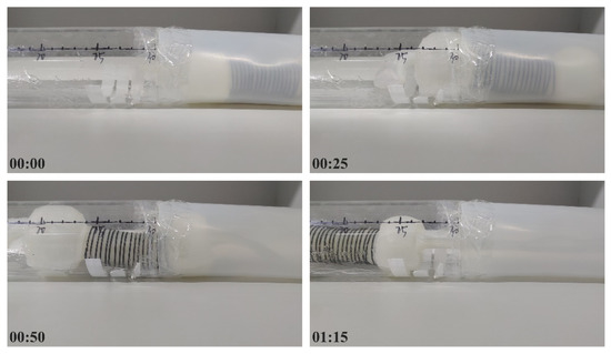
Figure 9.
The intestinal soft robot moves from a flexible pipe to a rigid pipe. (The number represents the running time of the soft robot.)
4.4. Experiment in a Mucus-Containing Pipe
To further test the performance of the intestinal soft robot, another experiment was performed in a special transparent pipe, where a certain amount of “mucus” (Liquid silica gel, Laponite RD, 2% concentration) was poured into the pipe. There is a large amount of mucus on the actual intestinal surface, and the mucus added here can better simulate the intestinal surface environment. However, the mucus reduces the friction force between the intestinal soft robot and the intestinal surface. It prolongs the anchoring process and makes the anchored actuators slide easily, and it also inevitably reduces the load capacity of the intestinal soft robot, which makes the functions performance of the intestinal soft robot more difficult. The experiment repeats the moving and grasping of an object at a fixed point, and the state at several moments during the movements is shown in Figure 10. The result shows that the intestinal soft robot still moves freely and extracts the object successfully in the mucus-containing pipe, and the speed is up to 14 cm/min, which is faster than that in the pipe without mucus, because, in other words, the reduction of the friction force results in a reduction of the shrinkage time of the central axial actuator.
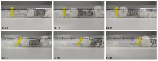
Figure 10.
The intestinal soft robot moves inside a mucus-containing pipe. (The number represents the running time of the soft robot.)
5. Conclusions
In order to overcome the shortcomings of the traditional endoscope, this work provides a pneumatic soft robot equipped with a soft gripper for potential application in intestinal surgery. This intestinal soft robot successfully completed the tasks of crawling and extracting objects at a fixed point in rigid pipe, flexible pipe and mucus-containing pipe, respectively, which prove the possibility of its applications in intestinal examination and treatment. The ultimate weight that the intestinal soft robot can extract was up to 220 g, and the maximum moving speed was 12.0 cm/min when the load was 9.9 g. This work provides a potential and patient-friendly approach to the examination and treatment of the intestinal diseases. In the future, we will further optimize the structure of the intestinal soft robot to make it easier to enter human intestines and also optimize the gripper so that it can bend in different directions.
Supplementary Materials
The following supporting information can be downloaded at: https://www.mdpi.com/article/10.3390/machines10111057/s1, Figure S1: Electropneumatic diagram of the system; Figure S2: Circuit diagram of the system.
Author Contributions
Conceptualization, G.L. and W.Q.; methodology, M.W.; software, W.Q.; validation, G.L., W.Q. and H.W.; formal analysis, M.W.; investigation, H.W.; resources, G.L.; data curation, W.Q.; writing—original draft preparation, W.Q.; writing—review and editing, G.L. and W.Q.; visualization, G.L. and W.Q.; supervision, G.L. and F.L.; project administration, F.L.; funding acquisition, G.L. and F.L. All authors have read and agreed to the published version of the manuscript.
Funding
This research was funded by the National Natural Science Foundation of China, grant number 61903157 and number 61833007, and the Joint Open Fund of the State Key Laboratory of Robotics, grant number 2021- KF-22-04.
Data Availability Statement
Not applicable.
Conflicts of Interest
The authors declare no conflict of interest.
References
- Roberts, J.A.; Cumberland, P.; Sockett, P.N.; Wheeler, J.; Rodrigues, L.C.; Sethi, D.; Roderick, P.J.; on behalf of the IID Study Executive. The study of infectious intestinal disease in England: Socio-economic impact. Epidemiol. Infect. 2003, 130, 1–11. [Google Scholar] [CrossRef] [PubMed]
- German, A.J.; Hall, E.J.; Day, M.J. Chronic intestinal inflammation and intestinal disease in dogs. J. Vet. Intern. Med. 2003, 17, 8–20. [Google Scholar] [CrossRef] [PubMed]
- ASGE Technology Committee; Chauhan, S.S.; Manfredi, M.A.; Dayyeh, B.K.A.; Enestvedt, B.K.; Fujii-Lau, L.L.; Komanduri, S.; Konda, V.; Maple, J.T.; Murad, F.M.; et al. Enteroscopy. Gastrointest. Endosc. 2015, 82, 975–990. [Google Scholar] [CrossRef] [PubMed]
- Akyuz, U.; Akyuz, F. Diagnostic and therapeutic capability of double-balloon enteroscopy in clinical practice. Clin. Endosc. 2016, 49, 157–160. [Google Scholar] [CrossRef] [PubMed]
- Lee, C.; Kim, M.; Kim, Y.J.; Hong, N.; Ryu, S.; Kim, H.J.; Kim, S. Soft robot review. Int. J. Control. Autom. 2017, 15, 3–15. [Google Scholar] [CrossRef]
- Firouzeh, A.; Paik, J. Grasp mode and compliance control of an under-actuated origami gripper using adjustable stiffness joints. IEEE-ASME T. Mech. 2017, 22, 2165–2173. [Google Scholar] [CrossRef]
- Almubarak, Y.; Tadesse, Y. Twisted and coiled polymer (TCP) muscles embedded in silicone elastomer for use in soft robot. Int. J. Intell. Robot. 2017, 1, 352–368. [Google Scholar] [CrossRef]
- Rus, D.; Tolley, M.T. Design, fabrication and control of soft robots. Nature 2015, 521, 467–475. [Google Scholar] [CrossRef] [PubMed]
- Bruder, D.; Remy, C.D.; Vasudevan, R. Nonlinear system identification of soft robot dynamics using koopman operator theory. In Proceedings of the 2019 International Conference on Robotics and Automation (ICRA), Montreal, QC, Canada, 20–24 May 2019; pp. 6244–6250. [Google Scholar] [CrossRef]
- Renda, F.; Cacucciolo, V.; Dias, J.; Seneviratne, L. Discrete cosserat approach for soft robot dynamics: A new piece-wise constant strain model with torsion and shears. In Proceedings of the 2016 IEEE/RSJ International Conference on Intelligent Robots and Systems (IROS), Daejeon, Korea, 9–14 October 2016; pp. 5495–5502. [Google Scholar] [CrossRef]
- Walsh, C. Human-in-the-loop development of soft wearable robots. Nat. Rev. Mater. 2018, 3, 78–80. [Google Scholar] [CrossRef]
- Majidi, C. Soft robotics: A perspectivecurrent trends and prospects for the future. Soft Robot. 2014, 1, 5–11. [Google Scholar] [CrossRef]
- Chan, J.; Pan, F.T.; Li, Z. Design and motion control of biomimetic soft crawling robot for GI tract inspection. In Proceedings of the 2018 13th World Congress on Intelligent Control and Automation (WCICA), Changsha, China, 4–8 July 2018; pp. 1366–1369. [Google Scholar] [CrossRef]
- Heung, H.; Chiu, P.W.Y.; Li, Z. Design and prototyping of a soft earthworm-like robot targeted for GI tract inspection. In Proceedings of the 2016 IEEE International Conference on Robotics and Biomimetics (ROBIO), Qingdao, China, 3–7 December 2016; pp. 497–502. [Google Scholar] [CrossRef]
- Manfredi, L.; Capoccia, E.; Ciuti, G.; Cuschieri, A. A soft pneumatic inchworm double balloon (SPID) for colonoscopy. Sci. Rep. 2019, 9, 11109. [Google Scholar] [CrossRef] [PubMed]
- Yan, G.; Ye, D.; Zan, P.; Wang, K.; Ma, G. Micro-robot for endoscope based on wireless power transfer. In Proceedings of the 2007 International Conference on Mechatronics and Automation, Harbin, China, 5–8 August 2007; pp. 3577–3581. [Google Scholar] [CrossRef]
- Calderón, A.; Ugalde, J.C.; Zagal, J.C.; Pérez-Arancibia, N.O. Design, fabrication and control of a multi-material-multi-actuator soft robot inspired by burrowing worms. In Proceedings of the 2016 IEEE International Conference on Robotics and Biomimetics (ROBIO), Qingdao, China, 3–7 December 2016; pp. 31–38. [Google Scholar] [CrossRef]
- Tang, Z.; Lu, J.; Wang, Z.; Ma, G.; Chen, W.; Feng, H. Development of a new multi-cavity pneumatic-driven earthworm-like soft robot. Robotica 2020, 38, 2290–2304. [Google Scholar] [CrossRef]
- Qi, Q.; Teng, Y.; Li, X. Design and characteristic study of a pneumatically actuated earthworm-like soft robot. In Proceedings of the 2015 International Conference on Fluid Power and Mechatronics (FPM), Harbin, China, 5–7 August 2015; pp. 435–439. [Google Scholar] [CrossRef]
- Yan, J.; Dong, H.; Zhang, X.; Zhao, J. A three-chambed soft actuator module with omnidirectional bending motion. In Proceedings of the 2016 IEEE International Conference on Real-time Computing and Robotics (RCAR), Angkor Wat, Cambodia, 6–10 June 2016; pp. 505–510. [Google Scholar] [CrossRef]
- Da Veiga, T.; Chandler, J.H.; Pittiglio, G.; Lloyd, P.; Holdar, M.; Onaizah, O.; Alazmani, A.; Valdastri, P. Material characterization for magnetic soft robots. In Proceedings of the 2021 IEEE 4th International Conference on Soft Robotics (RoboSoft), New Haven, CT, USA, 12–16 April 2021; pp. 335–342. [Google Scholar] [CrossRef]
Publisher’s Note: MDPI stays neutral with regard to jurisdictional claims in published maps and institutional affiliations. |
© 2022 by the authors. Licensee MDPI, Basel, Switzerland. This article is an open access article distributed under the terms and conditions of the Creative Commons Attribution (CC BY) license (https://creativecommons.org/licenses/by/4.0/).