1. Introduction
Although micro-mobility devices such as bicycles, scooters, and skateboards provide an alternative solution for metropolitan transportation, damages from related accidents have been rapidly increasing [
1,
2,
3,
4]. The National Electronic Injury Surveillance System (NEISS) shows that the number of e-scooter injuries increased by 365 percent between 2014 and 2018, and they were mostly head injuries [
5]. For this reason, helmets are perhaps the most important protective equipment when using micro-mobility devices. Joseph et al. [
6] assessed the relationship between helmet and Traumatic Brain Injury (TBI) severity after bicycle accidents. According to this study, helmets reduced the risk of severe TBI and death by 51% and 44% respectively. Outside of the challenges confronting the shared micro-mobility industry, society faces other impending challenges. Climate change may be the most serious of them all, because the creation, manufacturing, and implementation of goods and services all have a direct impact on the world, necessitating a rapid shift to more environmentally friendly socio-technical systems [
7]. The United Nations’ 2030 Agenda for Sustainable Development arose from this need, and the main goals are priorities in sustainable industrialization, consumption, and production patterns [
8,
9].
Cork is a natural material derived from the bark of cork oak (
Quercus suber L.) tree, which is removed without harming the tree regularly, usually every 9–12 years [
10,
11]. As the world seeks environmentally friendly materials, cork harvesting is a natural, regenerative process that reduces subsequent carbon footprints [
12]. Cork composites, based on the byproducts of stopper production in agglomerated form, exhibit excellent properties under impact and damping conditions because of their cellular microstructure that is highly effective in energy dissipation [
13]. Varela et al. [
9] evaluated the impact performance of agglomerated cork by comparing three different commercial headbands constructed with synthetic foams. They found that cork gives equivalent, or even better, results than synthetic ones. Several studies have been conducted regarding the impact resistance properties of cork materials [
14,
15,
16] and while having anti-impact properties [
17,
18], it also has excellent energy-absorbing and Vibro-damping capacity to use in structures that are exposed to destructive external forces [
19,
20,
21,
22]. Agglomerated cork displays the compressive behavior of cellular materials, which is illustrated by three zones on the stress-strain curve [
23,
24]. Under light strain, the cellular material shows elastic behavior. Since face membranes flex, cell edges in cellular solids with closed-cell display both bending and stretching/contracting, increasing axial stiffness. As the strain increases, the stress-strain curve plateaus, and, as with elastomeric foams, the plateau area is regulated by cell collapse caused by elastic buckling of the cell walls. For closed-cell cellular solids, the compression of the gas inside the cells and the stretching of the face membranes generates a gradual rise in stiffness [
25]. Agglomerated cork may nearly completely regain its former shape after compression. This capacity is related to the high recoverable strain induced by buckling of the elastic cell wall. Previous research [
24,
26] has demonstrated that agglomerated cork may absorb energy under a range of situations. This gives agglomerated cork an edge over stiff and semi-rigid synthetic foams, where the absorbed energy is unrecoverable after the elastic zone is exceeded due to plastic dissipation and brittle breakage. In addition, all cork components can be recycled, collecting CO
2 fixed by the cork tree over its lifespan, delaying its release into the environment and they are a “carbon neutral” substance. It should be noted that producing 1000 cork stoppers produces 1.5 kg of CO
2 whereas producing the same number of plastic stoppers and screw caps produces 14 and 37 kg of CO
2, respectively [
12,
27,
28,
29].
In multi-layer structures, cork presents higher energy absorbing capacities compared to high-performance foams, but shows large deformations at the same time. Inserting some unique materials such as WKSF, less deformation is observed in the multi-layer structures when exposed to impact loadings. WKSFs are advanced 3D fabrics produced by v-bed weft knitted machines and their structure is made up of three layers, the top layer, the spacer layer, and the bottom layer. These structures play an important role in safeguarding applications by absorbing excessive impact forces due to their variable thickness and distinctive three-dimensional structures [
30,
31,
32,
33]. 3D spacer textiles go above and beyond to meet the needs of a wide range of applications. Spacer fabrics are novel materials that are breathable, cushioned, and durable that is, they retain their form while remaining pleasant to the touch. Spacer textiles are a more environmentally friendly alternative to foam since they are more durable, preserve their cushioning capabilities, are energy absorbent, and are recyclable. Spacer yarns within WKSFs play a determining role in the deformation behavior of the structures. Impact resistance enhances as the number of spacer yarns increases in the textile. Moreover, thick spacer connections provide higher stiffness for the structures [
33,
34].
The use and design of drop-weight impact devices for use in low-velocity impact tests have been widely used due to their standardization and sufficient accuracy, availability, dependability, and reproducibility. Impact tests are the most typical method for evaluating energy absorption. There are several drop towers that are commercially available, however, they are quite expensive and frequently not suited for evaluating designed materials due to their range of drop energy. Therefore, designing an effective and low-cost drop-tower system can be important for engineering applications. The model developed in this study, based on the sensitive dynamometer of Kistler company, has resulted in obtaining acceptable data for measuring the reaction forces and finally calculating the energy absorption of the designed samples. In the present study, cork and WKSF-based multi-layer composites were designed as eco-friendly, protective structures for micro-mobility devices. Protective properties were evaluated based on the impact force and energy absorption data that were obtained from low velocity drop tests. In the drop tests, a hemispherical impactor loaded with 1.1 kg was dropped from different heights (0.25, 0.50, and 1.00 m) on the specimens. Eight different multi-layer configurations were created. To compare the primary design configurations (3 to 8), Configs-1 and 2, which are full-cork and full-WKSF, were included. After the test, the results of maximum reaction force, energy absorption, and specific energy absorption are discussed separately. One of the goals of this study is to observe whether the combination of WKSF and cork, which are materials with high energy absorption properties, can further improve their energy-absorbing properties. The positioning of layers in multi-layered structures, which can have a significant effect on protective performance, was investigated. In addition to anti-impact behavior, eco-friendly properties were investigated by conducting LCA for each configuration. Human Health Impacts (HHI), Ecosystem Quality Impacts (EQI), and Resource Impacts (RI) metrics were considered in the LCA results.
2. Experimental Details
2.1. Drop-Weight Impact Machine
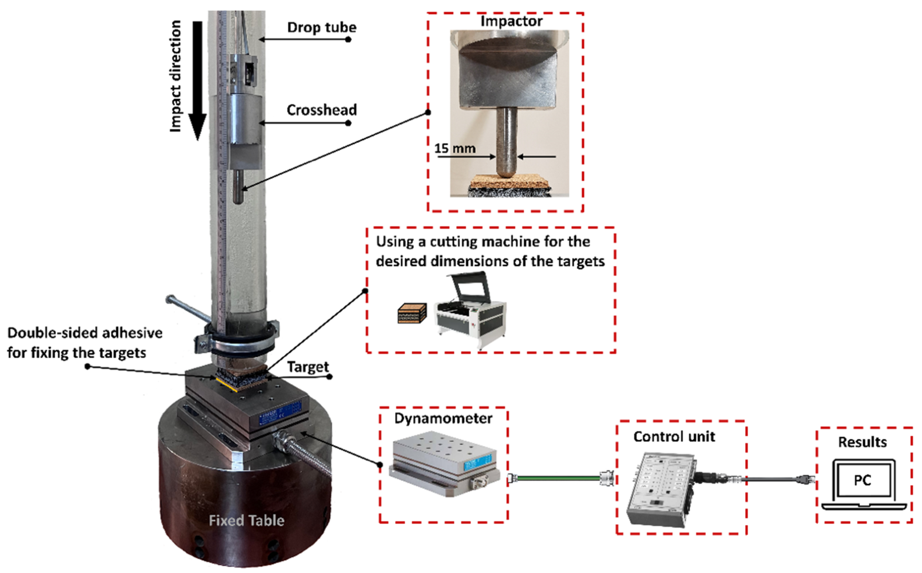
The drop-weight testing machine (
Figure 1), which can eliminate numerous impacts, was used to conduct the low-velocity impact tests. A wide range of impact energies are possible thanks to the impactor’s variable mass and drop height. Multi-layer composites were impacted by dropping a hemispherical impactor with a diameter of 15 mm. The impactor was loaded by 1.1 kg and dropped from 0.25, 0.50, and 1.00 m which corresponds 2.69, 5.39, and 10.79 J of impact energy, respectively. A 9257B-quartz 3-component dynamometer, which is an intelligent grid tool used to determine the force being applied to the unit being tested at the desired moment, was placed under the specimens for measuring the reaction force of targets. We can measure the three axes of the force vector, Fx, Fy, and Fz, thanks to the dynamometer setup. This dynamometer has a measurement range of −5 to 10 kN of force in the direction of Fz, up to a frequency range of 3.5 kHz. In this study, we measured the reaction forces following the collision impact on the targets using the Fz axis. Also, the device is able to calculate the moment Mx, My, and Mz based on the force applied and the position of the sensors in the dynamometer. Dynamometers are the preferred solution for demanding and highly dynamic testing applications and for complicated and extremely dynamic testing applications, they are the ideal choice. Depending on a dynamometer, the usage of piezoelectric technology allows for incredibly wide measuring ranges. It is possible to measure small forces and impacts, such as the one caused by the screw falling, thanks to the response of eigenfrequencies. These frequencies are achieved by the very rigid design with the base plate and a top plate combination with very rigid piezoelectric force sensors. The force sensors are placed between the plates and preloaded such that these characteristics are achieved. The dynamometer used in this study is based on four piezoelectric triax force sensors. Apart from the dynamometer’s size, there are differences in the materials used in dynamometers, which are typically ceramic, stainless steel or aluminum top plates. As a result, the useable frequency range can be greatly expanded. Dynamometers with ceramic top plates are mainly used in micro-vibration applications, for example for the dynamic characterization which goes into space with the aim of minimizing vibrations. So, size and material are two important factors. A third distinguishing feature is the direction of the preloading of the four piezoelectric force sensors. However, it has a greater influence on the behavior of the dynamometer if the temperature changes during the test. In the dynamometer used in this study, the four force sensors are located and preloaded between the base plate, at the bottom, and at the top plate on top like a sandwich. Since the preloading direction is vertical, using a vertically preloaded dynamometer is acceptable for many applications. Dimensions of the test object, expanded force level, thermal impacts, and specific conditions are considerations to make before choosing a dynamometer. The dynamometer includes a 3-channel charge amplifier. As a result, the dynamometer’s output signal has a low impedance. The integrated cable is connected to the Type 5233A1 control unit. The four measuring ranges can be divided into two groups by the control unit. The control unit is simple to use and includes a power supply, a keyboard with status displays, and a signal input connector. The output voltages are proportional to the applied impact forces. The control unit has an output signal of ±5 V and a frequency range of 200 Hz.
Figure 1 depicts the drop tower impact machine.
2.2. Preparation of Targets
Multi-layer composites were assembled by using two main components. Cork layers were provided by Ducork Inc. (Istanbul, Turkey), whereas WKSF layers were provided by Ames Europe Inc. (Enschede, The Netherlands).
Table 1 gives the details of the components based on the manufacturers’ specifications. In the preparation of the composites, each layer was sized into 50 mm × 50 mm, and was cut by a laser cutting machine and stacked to assemble the multi-layer structures. Multi-layers were designed in 8 different configurations. Configs-1 and 2, which are full-cork and full-WKSF, were added to compare the main design configurations (3 to 8). The weight of Config-1 is 9 g, Config-2 is 14 g, and Configs 3 to 8 are 11.5 g.
Figure 2 shows the multi-layer composite configurations used in this work.
2.3. Life Cycle Assessment
The impact assessment method selected was the ReCiPe V1.11 Hierarchist Method, was created by RIVM, CML, Pré Consultants, Radboud Universiteit Nijmegen, and CE Delft. This method refers to the normalization values of Europe with the weighting set belonging to the hierarchic perspective. The impact categories, and endpoints, are Human Health Impacts (HHI), Ecosystem Quality Impacts (EQI), and Resource Impacts (RI). HHIs, in DALY (Disability Adjustable Life Year), and are the sum of the following midpoints: climate change, ozone depletion, human toxicity, photochemical oxidant formation, particulate matter formation, and ionizing radiation. EQIs, in species.yr, are the sum of the following midpoints: climate change, terrestrial acidification, freshwater eutrophication, ecotoxicity (on terrestrial, freshwater, and marine), occupations (agricultural and urban lands), natural land transformation. Finally, RI, in USD, consists of the fossil depletion midpoint.
The software tool Sima Pro 7.2 was used to determine all impacts. Mainly, the weight data of eight different types of configurations were used. Furthermore, the Ecoinvent v2.0 database was used to complete the life cycle assessment. The LCA methodology allows the identification of environmental impacts from the processes, products, and systems under consideration. In the current study, primarily different materials are determined, and the following initial hypothesis conditions are defined for the calculations:
3. Results and Discussion
3.1. Anti-Impact Properties of the Composites
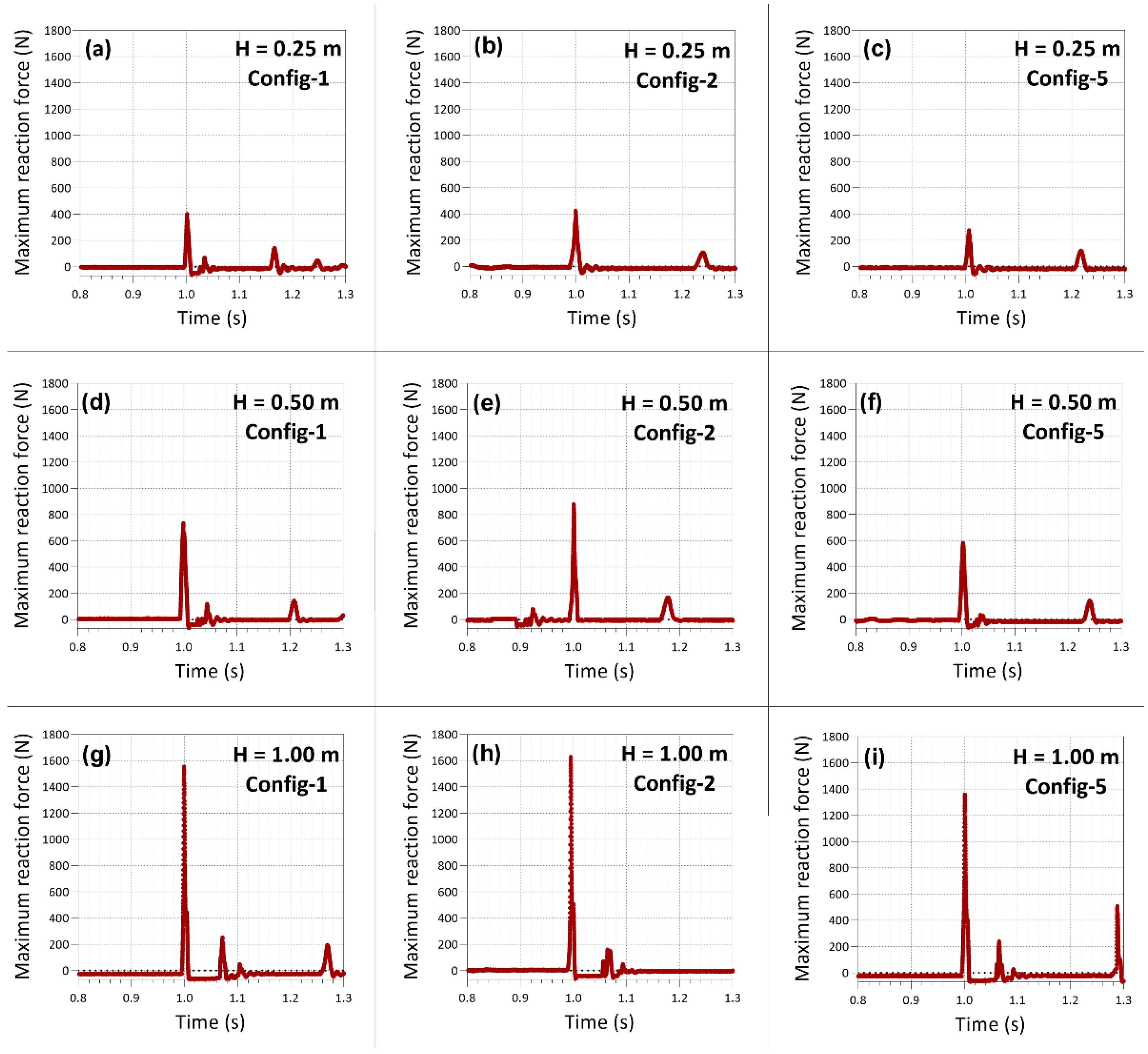
The impact response curves for Config-1, Config-2, and Config-5 are shown in
Figure 3. The large peaks at about 1 s correspond to the main impact forces on the back face of the composites at the impact instants. Following the main peaks, smaller peaks show the responses caused by the rebounding impactor. For ease of evaluation, the main peaks were considered and plotted for each configuration in
Figure 4. Maximum reaction force is critical for evaluating the protective behavior of structures, and it is recommended that it is maintained low, to reduce damage to the back face. Instead of transmitting the impact force in the impact direction, it should be spread in-plane directions. According to the maximum reaction forces, the full-cork structure (Config-1) leads to lower peaks in comparison to the full-WKSF structure (Config-2) for each drop height. However, WKSF incorporation in the cork layers provides further reduction in reaction forces, depending on the sequence of the layers. Considering the reaction force results, composites having cork at the top layers (Configs 3, 5, 7) are better at lowering the impact forces than the full-cork structure (Config-1). However, configurations with the top layer of WKSF (Configs 4, 6, 8) are not effective in reducing the impact forces. The WKSF layer is flexible and shows local compression type deformation under point contact loading. On the other hand, the cork layer is stiff and thereby shows whole-body motion rather than local deformation under point loading. For this reason, point loading in impact conditions is distributed over a larger area at the top cork layer. This mechanism reveals the efficiency of WKSF under the cork layers. The whole-body motion of top cork layers provides a distributed loading for the below WKSF layers and therefore, WKSF is elastically compressed to a large extent by absorbing a large amount of loading [
35,
36]. From the results, Config-3 shows the lowest reaction forces for each drop height, since the core WKSF layers are effectively compressed between the top and bottom cork layers in compliance with the aforementioned mechanism.
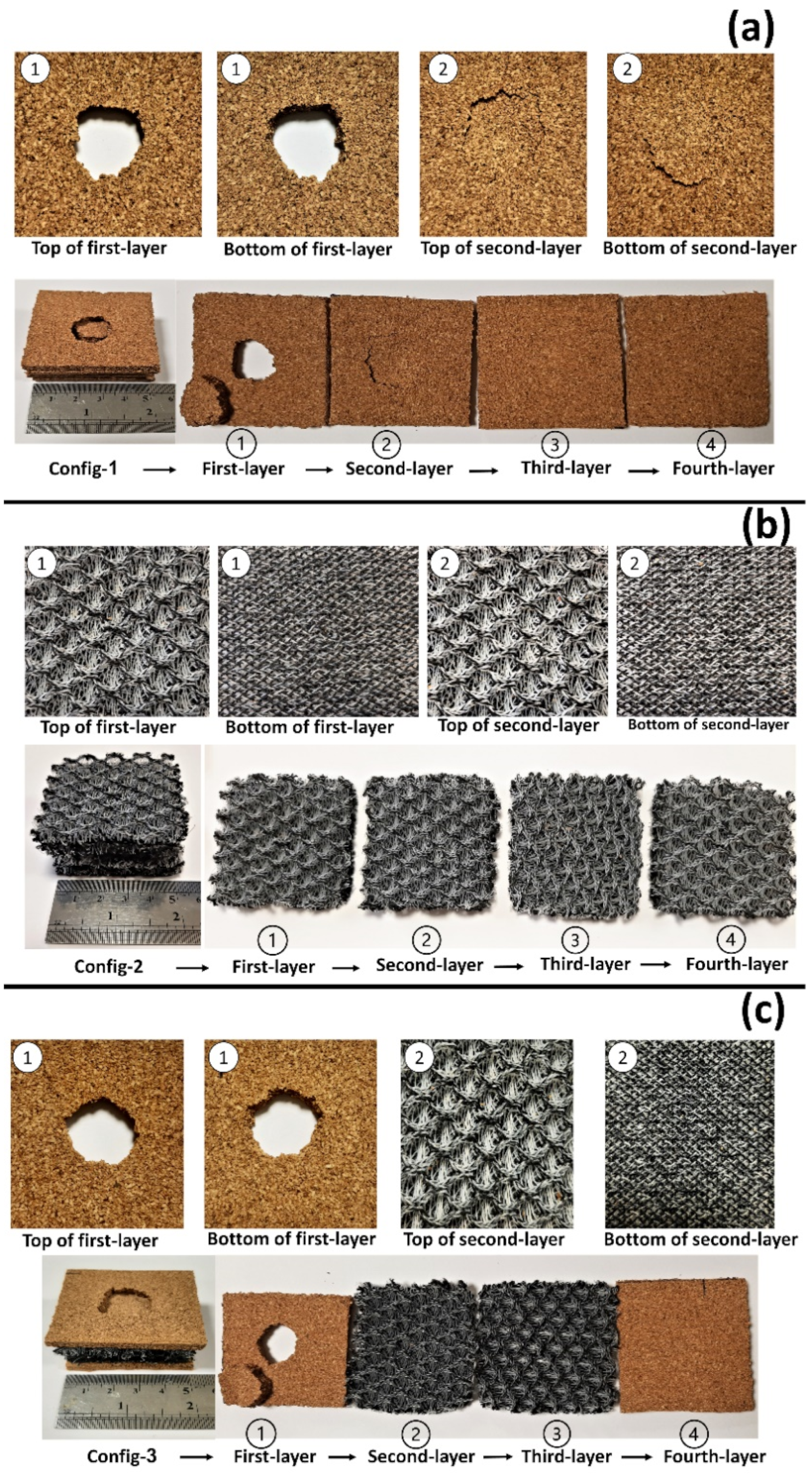
Figure 5 shows the energy absorbing capacities for each configuration. Considering Config-1 and Config-2, which are the reference designs, we can discuss their general anti-shock behavior. In Config-1, the cork absorbs more energy in the first and second layers, and the lower layers (third and fourth) feel less energy, so ultimately no deformation occurs (see
Figure 6). In Config-2, due to the flexible and durable three-dimensional structure of WKSF, impact energy is applied to all its layers and acts as an integrated mechanism. The first layers cannot dump as much energy in the first collision as cork can, but since deformation does not occur in the upper layers, the energy reaches the lower layers as well and the lower layers (third and fourth) of this configuration play a better role relative to the lower layers of Config-1.
Like the maximum reaction force results, energy absorbing capacities point out that Config-3 is the best design in energy attenuation. For the drop heights of 0.25, 0.50, and 1.00 m, Config-3 has the energy absorbing capacity of 2.46, 4.75, and 9.91 J respectively. This target is made up of a cork layer on top, two WKSF layers in the middle, and a cork layer on the bottom. The cork panels distribute impact energy in lateral directions. The lower layers of WKSF are subjected to whole-body compression rather than being distorted locally at the impact point because of the distributed energy at the top layer. As a result, the entire structure, including the far fields from the impact point, contributes to the energy-absorbing process.
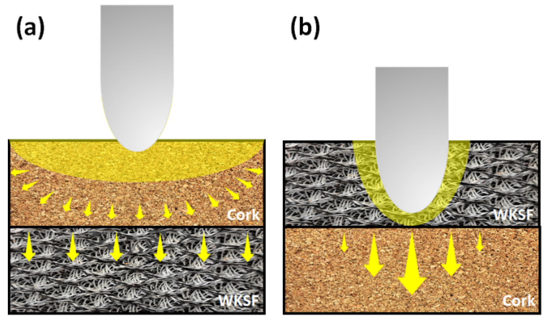
A similar effect is visible in Config-5 and Config-7, which follow the targets of Config-3 in energy-absorbing capacities. The position of WKSF layers emerges as a common key feature. At this point, it is possible to state that cork layers are more efficient than WKSF layers at the top layers. Configs 4, 6, and 8 have poor energy-absorbing capabilities due to the WKSF position at the top layers. In these designs, drop energy is accumulated on the impact point at the top WKSF layers instead of being distributed energy over the structures. This can be associated with the flexible texture of the WKSF layers that show local deformation at the impact point, and hardly receive the contribution of far-fields. This phenomenon is illustrated in
Figure 7. As shown in the sketch, the cork at the top layer can distribute the impact energy to the far fields and compress the lower WKSF layer. By this means, an entire body of the WKSF layer contributes to the energy absorption in addition to the contribution by the whole body of the cork layer. On the other hand, WKSF at the top layer conducts a large part of the impact energy to the lower layers. For this reason, far-fields of WKSF at top layers cannot be used efficiently to suppress the impact energy.
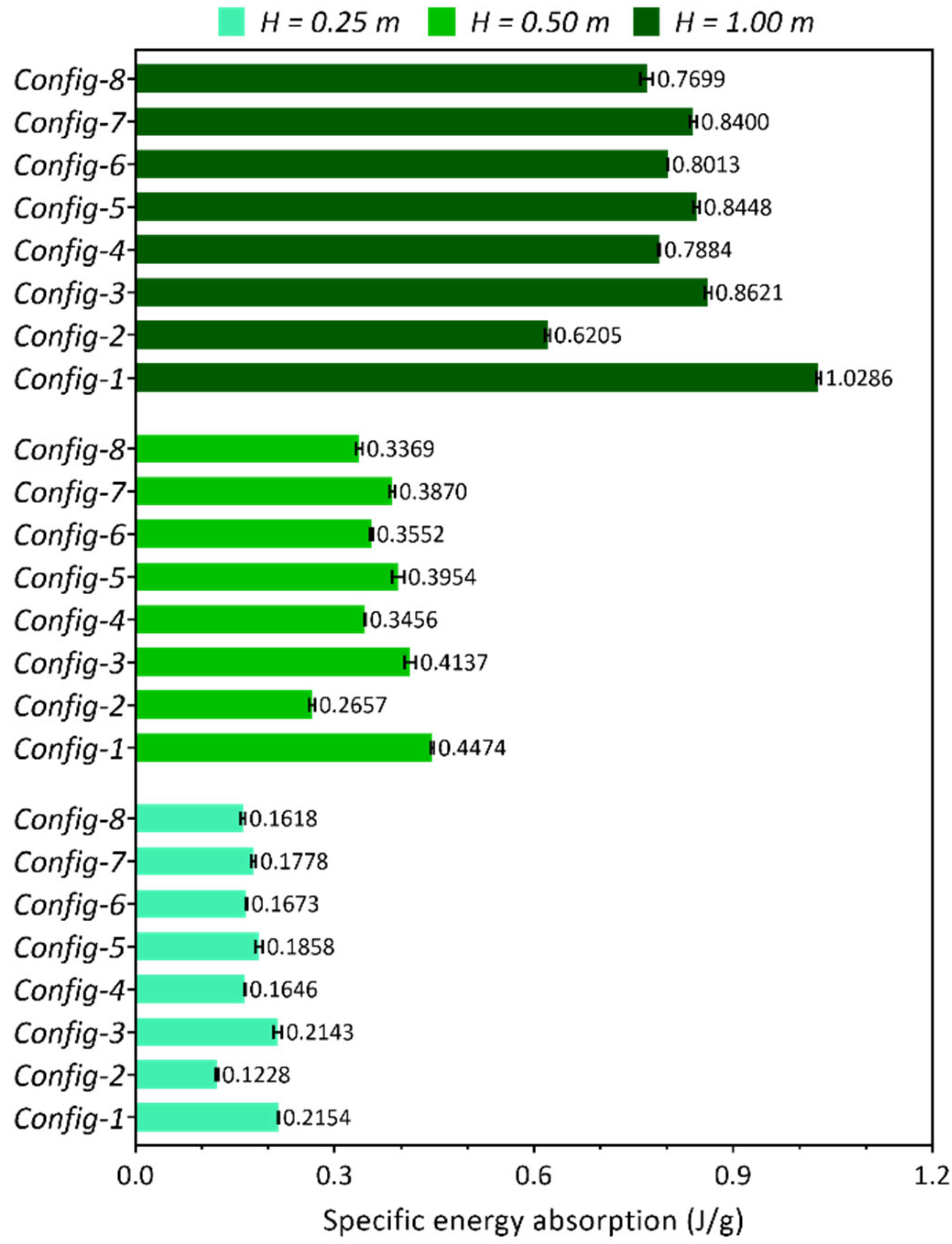
To consider the mass effect in target designs, specific energy absorbing capacities were calculated for each configuration. In this calculation, energy-absorbing capacities were divided by the target masses. Hence, energy absorption per unit mass was obtained for each target as shown in
Figure 8. As mentioned before, Configs 1 and 2 were added to the design of this study to compare with the main design Configs (3 to 8) which are a combination of cork and WKSF. According to the results, the full-cork target (Config-1) comes to the fore due to the fairly low density of cork layers, despite its lower energy absorbing capacity in comparison to Configs 3, 5 and 7. Although Configs 3, 5, and 7 are the most efficient targets in energy absorption, the WKSF layers included in these designs lead to a mass gain to the targets. Hence, these targets have a loss of performance in terms of specific energy-absorbing capacity. On the other hand, the full-WKSF design (Config-2) exhibits the lowest performance among the targets. Since Config-2 consists full of WKSF layers, it is the heaviest target among all the configurations. In addition to its low mass score, Config-2 shows the lowest energy absorbing performance recalling
Figure 5. For this reason, this target significantly falls behind the other configurations in terms of the energy absorbing results. A similar effect is shown in Configs 4, 6, and 8. These targets already have moderate energy absorbing performance, and thereby drop behind in energy absorbing per unit mass due to the WKSF layer contents.
Considering maximum reaction forces, energy absorbing, and specific energy absorbing capacities, it can be mentioned that WKSF is an important component in suppressing the impact forces and impact energies. However, the position of WKSF in multi-layer structures should be carefully decided. If the mass of the structure is not a priority in the application, WKSF can be effectively used in multi-layer systems. However, this component should be located under a cork layer to benefit from the stiffer structure of the cork. On the other hand, if the mass of the structure is an issue in the application, the full-cork configuration provides better performance for the users.
3.2. Life Cycle Assessment of the Composites
As described in the modeling section, we divided the specimens into three groups based on their contents. Config-1 is manufactured by a full-cork layer, and its components are agglomerated cork and polyurethane. Config-2 was manufactured with a full-WKSF layer, and its main material is polyester. Configs-3 to 8 were manufactured with a combination of cork and WKSF layers. According to LCI and the amount of the contributions, the impacts are given in
Table 2.
While the highest HHI was calculated as 1.46 DALY for Config-2, the lowest HHI was found as 2.88 × 10
−6 DALY for Config-1. The highest HHI values, around 80% of the total impact, were observed in the climate change midpoint. Among the configurations, the highest EQI was found as 0.0083 species.yr in Config-2. Such results in HHI have not been observed in the EQI. Only in Config-2 and Configs-3 to 8, the highest value was seen at the climate change midpoint, while in Config-1 it was in agricultural use areas. The highest EQI values for Config-1, Config-2, and Configs-3 to 8 were calculated as 0.0026, 0.0083, and 0.0049 species.yr, respectively. In addition, the lowest EQI value was found to be 2.66 × 10
−8 (in Marine ecotoxicity midpoint) in Config-1. Finally, the RI values for Config-1, Config-2, and Configs-3 to 8 were calculated as
$3.60,
$89.70, and
$46.70, respectively. The RI value was highest in Config-2 and lowest in Config-1. The total values of HHI, EQI, and RI are shown in
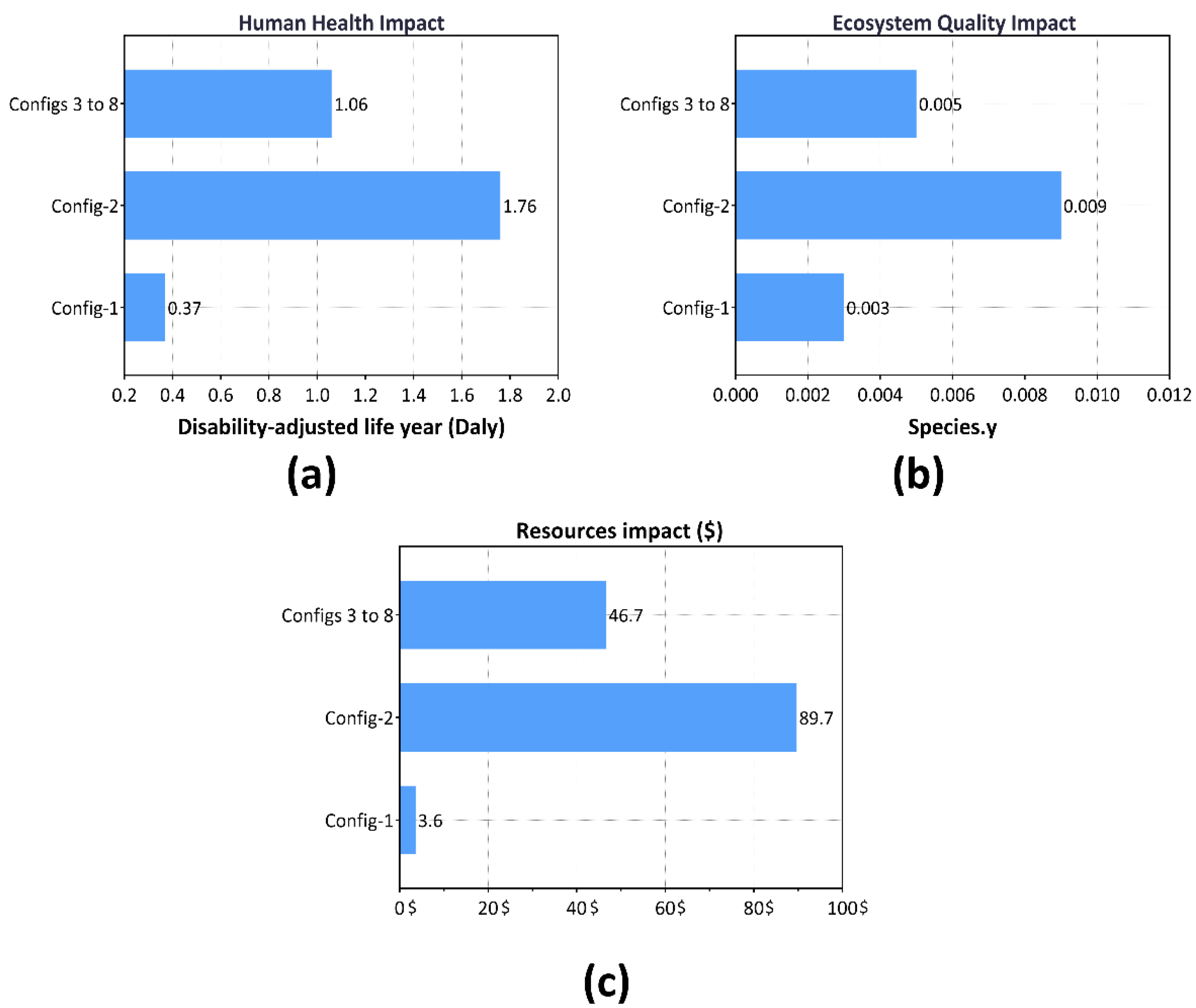
Figure 9.
The HHI values for Config-1, Config-2, and Configs-3 to 8 are 0.36, 1.76, and 1.06 DALY respectively. Config-1 has 4.8 times less HHI than Config-2 and 2.9 times less HHI than Configs-3 to 8. The EQI values for Config-1, Config-2 and Config-3 to 8 are 0.0028, 0.0086 and 0.0052 species.yr respectively. Config-1 has 3 times less EQI than Config-2 and 1.8 times less EQI than Configs-3 to 8. Finally, the RI values for Config-1, Config-2, and Configs-3 to 8 are $3.6, $89.7, and $46.7, respectively. Config-1 has 24.9 times less RI than Config-2 and 13.97 times less RI than Configs-3 to 8. Config-1 appears to be beneficial for reducing impacts on human health, ecosystem quality, and resources. The reason why the lowest values were obtained in Config-1 can be understood as the use of recycled materials (cork) instead of natural resources. The cork is manually harvested from the forests, and then motor-manual processed for thinning and final cutting of the trees. For this reason, specific to the case, Config-1 has been found to affect agricultural land use more than the other configurations.


