1. Introduction
Recently, issues, such as air pollution and global warming, have become more serious due to the increased consumption of fossil fuels. As a result, much research has been done on the effectiveness of natural energy production systems in dealing with these issues. Small wind power generation system is one of the most useful natural power generation technologies. Wind power generation systems use permanent magnet synchronous generators (PMSG), doubly-fed induction generators (DFIG), and induction generators. However, the induction generator has low efficiency but is durable and requires less maintenance. With the recent technological development and industry breakthrough, the switched reluctance generator (SRG) can be presented as an important candidate for the application of wind turbines with maximum power point tracking (MPPT) systems [
1,
2,
3,
4,
5].
The SRG has grown in popularity, importance, and interest among researchers. It is a strong candidate machine for clean power generation and its applications due to the many advantages that present this kind of system, such as its sturdy structure, which withstands high temperature and high torque. In contrast, it has some disadvantages, such as high torque ripple and high acoustic noise level due to the non-linear physical properties of the SRG and the lack of windings or magnets in the rotor simultaneously. The switching machines have a very robust design. These important properties make the SRG a viable alternative for aerospace and automotive applications where system reliability is critical. Magnetic independence between motor phases is due to the prominent pole arrangement. In another way, it is also responsible for torque ripples, especially, at high speeds and during phase shifts. Nevertheless, if an appropriate control method is used, smooth operation can be achieved. In order to reduce torque ripple, several research papers have been presented with the goal of improving SRG performance through improved control solutions [
6,
7,
8,
9,
10,
11,
12,
13].
The switched reluctance machine has two functional modes: motor mode and/or generator mode. For performance, the SRG relies on ferromagnetic linear actuators that optimize torque and power generation. Of these SRG performance improvement techniques, some are based on direct torque control (DTC), which is an independent process of controlling the torque for each phase except it is a complex mechanism. However, the direct instantaneous torque control (DITC) approach is efficient and has a simple algorithm that uses a hysteresis controller to process the required instantaneous torque. Several authors collaborated on the development of this kind of technique [
14,
15]. These researchers propose a four-quarter DITC process and compare it to the current conventional hysteresis control current (HCC). Indirect torque control (ITC), as described in references [
15,
16], is considered the subject of recent research. The advanced version of the ITC uses the current engagement feature to obtain the necessary torque.
The use of SRG with wind turbines, through a common shaft, converts mechanical into electrical energy thanks to its ability to work at various speeds. For these advantages, the system can be a powerful generator for small wind turbine generating systems and are increasingly popular for use in isolated and remote areas, such as mountains, islands, or skyscrapers [
4].
Several control strategies, to improve SRG performance in wind turbine applications, have been proposed, including various wind speeds and wind strengths. MPPT turbine power optimization was used to obtain optimal torque [
17,
18], and the torque ripple reduction algorithm was treated in many works [
15,
16,
19,
20,
21]. The importance of this work focuses on the association of the ITC control of the SRG with the MPPT of the wind turbine by considering the different effects of the system. The proposed system is more distinct in many details, which have been taken into account, whether in the control or in the used model, which is presented by applying the strategy on a nonlinear model of SRG 12/8 to obtain results closer to reality.
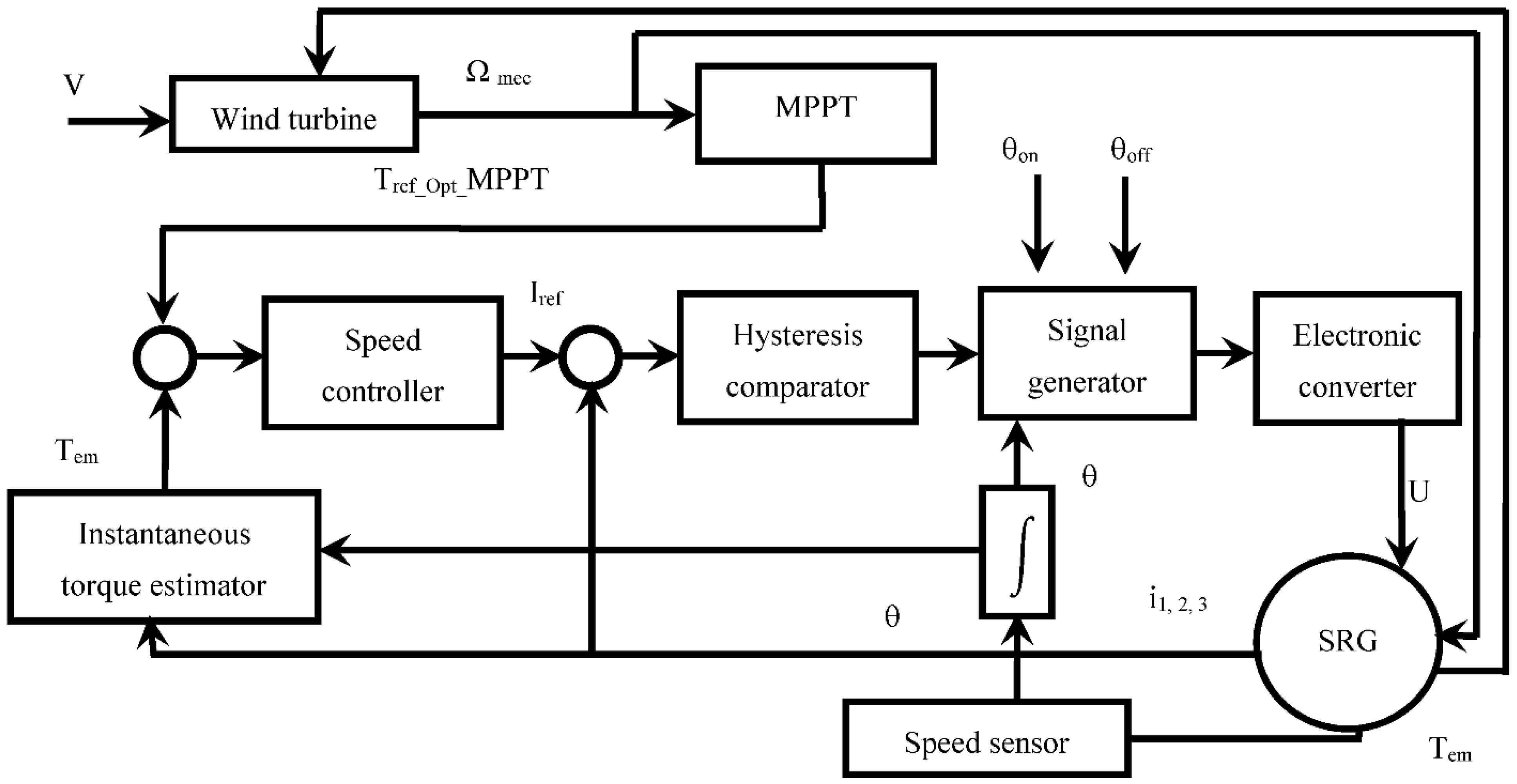
In this paper, machine modeling and wind turbine simulation, using the generator forbidden variables, are proposed. Then, the maximum power point tracking diagram technology of the turbine associated with the SRG control is treated; in the presence of the torque control loop and by the use of the ITC technique (
Figure 1).
Finally, we will present simulation results to check the performance of the SRG control coupled with the MPPT technique, as well as the effect of changing the switching angles θon and θoff.
2. SRG-Based Wind Turbine Design and Modeling
SRG is an ordinary machine, but the inherent nonlinearity makes it difficult to study and model. To overcome these difficulties, some of its properties will be determined by applying the FEM. This method permits to model and to extract the nonlinear magnetic properties of the SRG.
2.1. Switched Reluctance Generator Geometries
The physical operation of switched reluctance generator (SRG) is based on the principle of magnetic flux difference. In fact, their operation depends on the difference in magnetic flux. Any type of variable reluctance machine is made up of two parts in relative motion, one electrically active (the stator) and the other passive (the rotor). The first element consists of a toothed magnetic circuit with a coil. The second element consists of a ferromagnetic circuit, also toothed, but without conductors or permanent magnets. In the current study, the SRG 12/8 was chosen and the subject of an initial design is presented. The corresponding characteristics of the used SRG are given in
Table 1 [
22].
2.2. SRG Operating Modes
The principle of functioning in the SRG is essentially based on changing the magnetic reluctance to generate torque. Due to the variation of the air gap and magnetization of the magnetic circuit, the SRM presents a non-linear behavior. This phenomenon means that the SRG has a protrusion in the stator as well as in the rotor. Multiple SRG configurations can be created based on the number of rotor and stator poles, so the nonlinear permittivity coefficient is adopted under these assumptions.
The single-phase of SRG governs the following basic electromagnetic equation [
15,
22,
23,
24,
25,
26]:
where
is the inductance, i is the total current, and R is the resistance per phase. θ
m represents the relative position of the rotor-stator teeth. Ψ
is the totalized flux and Ω is the rotation angular speed.
The expression of the electromagnetic force (EMF) is presented as follows:
When each stationary pole is excited, the rotating pole closest to it is tilted to the lowest resistance position.
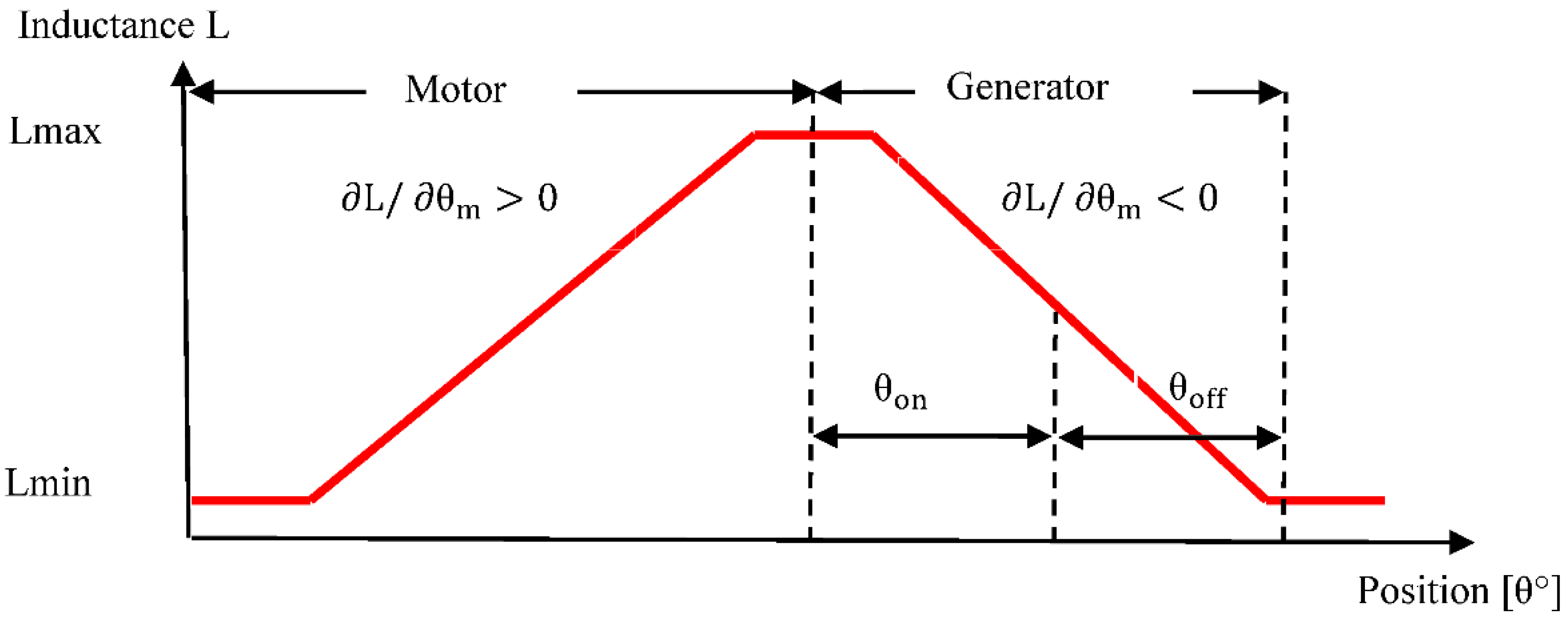
Figure 2 depicts an ideal inductance coil influenced by the single-phase currents in the motor and generation modes. Pushing the phase during the positive slope of the induction coil produces positive torque (motor mode) while pushing the phase during the negative slope produces negative torque (generation mode). Operation of the SR machine in motor and generator modes necessitates the use of a transformer topology to excite the phases at time with the position of the rotor, and the initial torque can be expressed as a change in combined force as a function of rotor position and current. In phase j, the torque equation is written as follows:
Powering the machine during the increasing or decreasing of the inductance phase will give the desired operating speed (
Figure 2):
Motor mode (Te > 0) on the increasing phase of the inductance (∂L/∂θm > 0),
Generator mode (Te < 0) on the decreasing phase of the inductance (∂L/∂θm < 0).
2.3. Finite Element Modeling Results
The finite element method is a powerful tool for the electromagnetic problem, especially in cases of complex geometry and high physical non-linearity, such as in the switched reluctance machine. Thus, by using the ANSYS software and by implementing the geometric parameters and the APDL program according to the selected studied SRG (12/8), we get high-performance results from the finite element modeling.
Figure 3 gives graphical and numerical results for the flux density of the SRM 12/8, where the rotor position is at the extreme (unaligned and aligned positions), for a current equal to 12 A.
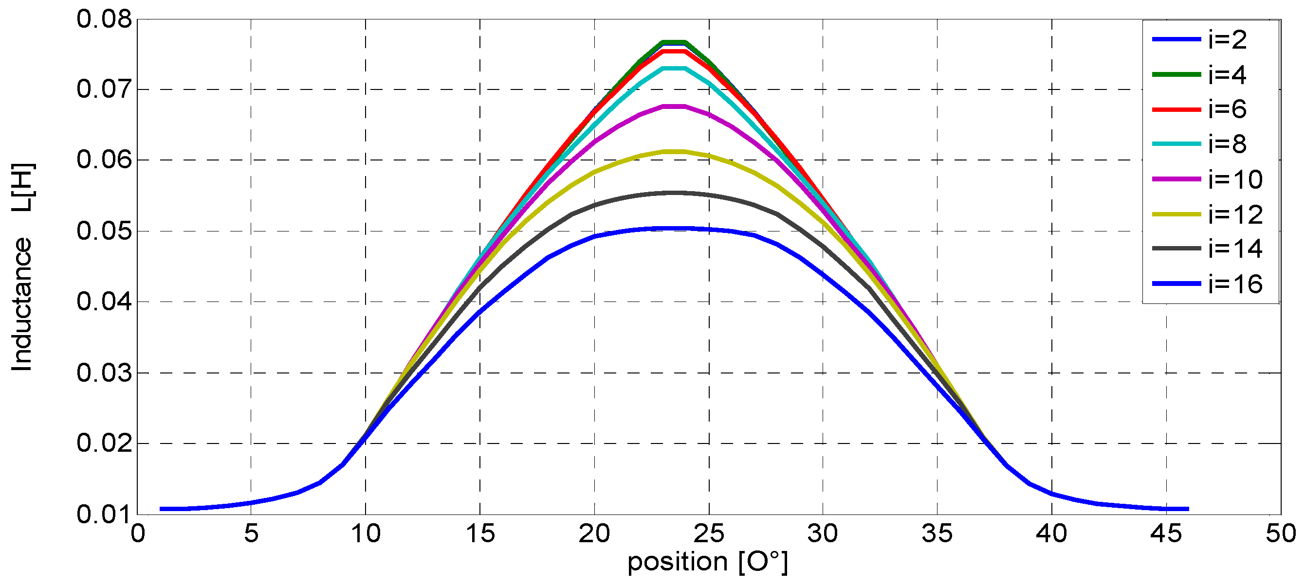
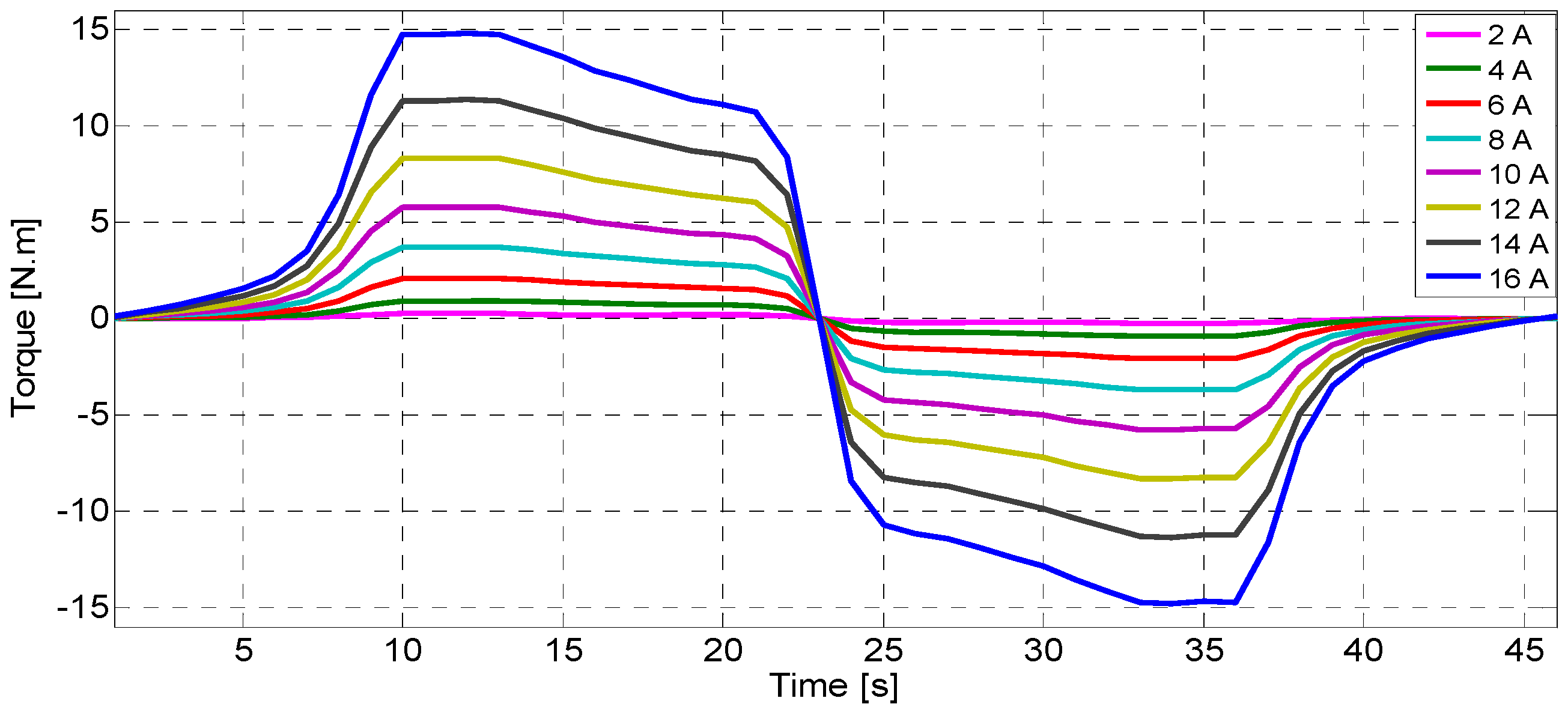
Figure 4 and
Figure 5 respectively show the numerical characteristics of the inductance and the static torque as functions of the rotor position from aligned to non-aligned, then, from non-aligned to aligned position. We note that the result is given for currents ranging from 2 to 16 A.
3. Wind Turbine
In order to study the wind energy process according to wind speed variation, it is necessary to describe the system under study when testing the MPPT control algorithm. This system consists of a wind turbine that produces the optimal torque of the SRG.
3.1. Modeling of the Wind Turbine
The wind power mathematical equation is given as follows:
The tip speed ratio λ is defined as:
where
is the radius of the blades of the wind turbine and
is the speed of the rotation of the wind turbine.
The aerodynamic torque T
t and the power coefficient C
p are defined as follows:
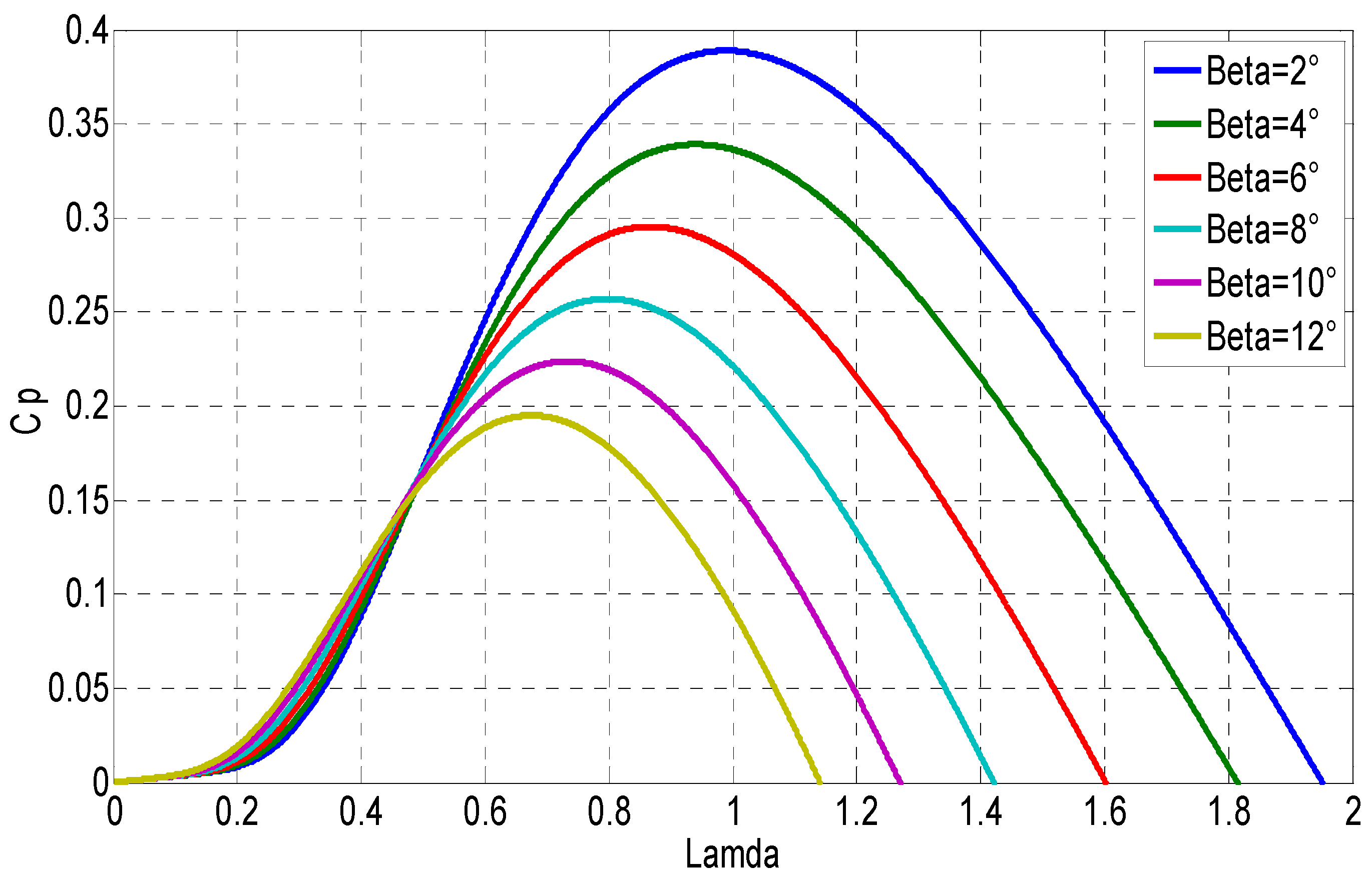
The theoretical maximum possible value of the power coefficient C
p, called the Betz limit, is equal to 16/27 ≅ 0.593 [
1,
24] (
Figure 6).
3.2. Model of the Gearbox
The gearbox ensures the adaptation of the slow speed of the turbine to the generator speed. It is mathematically modeled by a speed gain G such as:
3.3. Mechanical Shaft Modeling
The dynamic equation can be used to determine the mechanical transmission modeling. The following equation describes the mechanical system:
where
is the multiplier torque,
is the electromagnetic torque,
is the total inertia, and
is the coefficient of viscous friction.
3.4. Maximum Power Point Tracking
The concept of finding the maximum power point refers to the optimization of the generator speed relative to the wind speed, whereby the maximum mechanical power can be obtained. Many scholars have written on this subject and have proposed algorithms to describe the corresponding strategy.
Many MPPT strategies for wind turbines have been proposed in the literature [
17]. MPPT strategies designed in previous works use the parameters, such as the tip speed ratio, the optimal torque for optimal efficiency, or the relationship between turbine rotational speed and power.
The major forms of MPPT strategies include direct power control (DPC) and indirect power control (IPC) [
18,
27], as well as more sophisticated techniques utilizing neural networks (NN) and fuzzy logic controllers (FLC) [
28,
29].
The MPPT techniques based on indirect power control (IPC) can be categorized as the tip speed ratio, power signal feedback, and optimal torque [
30,
31,
32,
33].
The tip speed ratio method for the turbine is to generate the most power [
34]. The desired speed for the rotor and wind turbine is produced by estimation. The tip speed ratio method approach estimates the optimal power extraction by taking into account the system parameters. There are two methods, depending on the wind’s obtained speed. The first method relies on the mechanical sensor in use, whereas the second relies on an estimate of the wind’s speed [
35].
The power signal feedback method of the wind turbine is based on extracting the optimum power data or characteristic C
p = f(λ) by experimental test or by simulation. Then, using the look-up tables can generate power optimal in this strategy [
18]. The use of the characteristic C
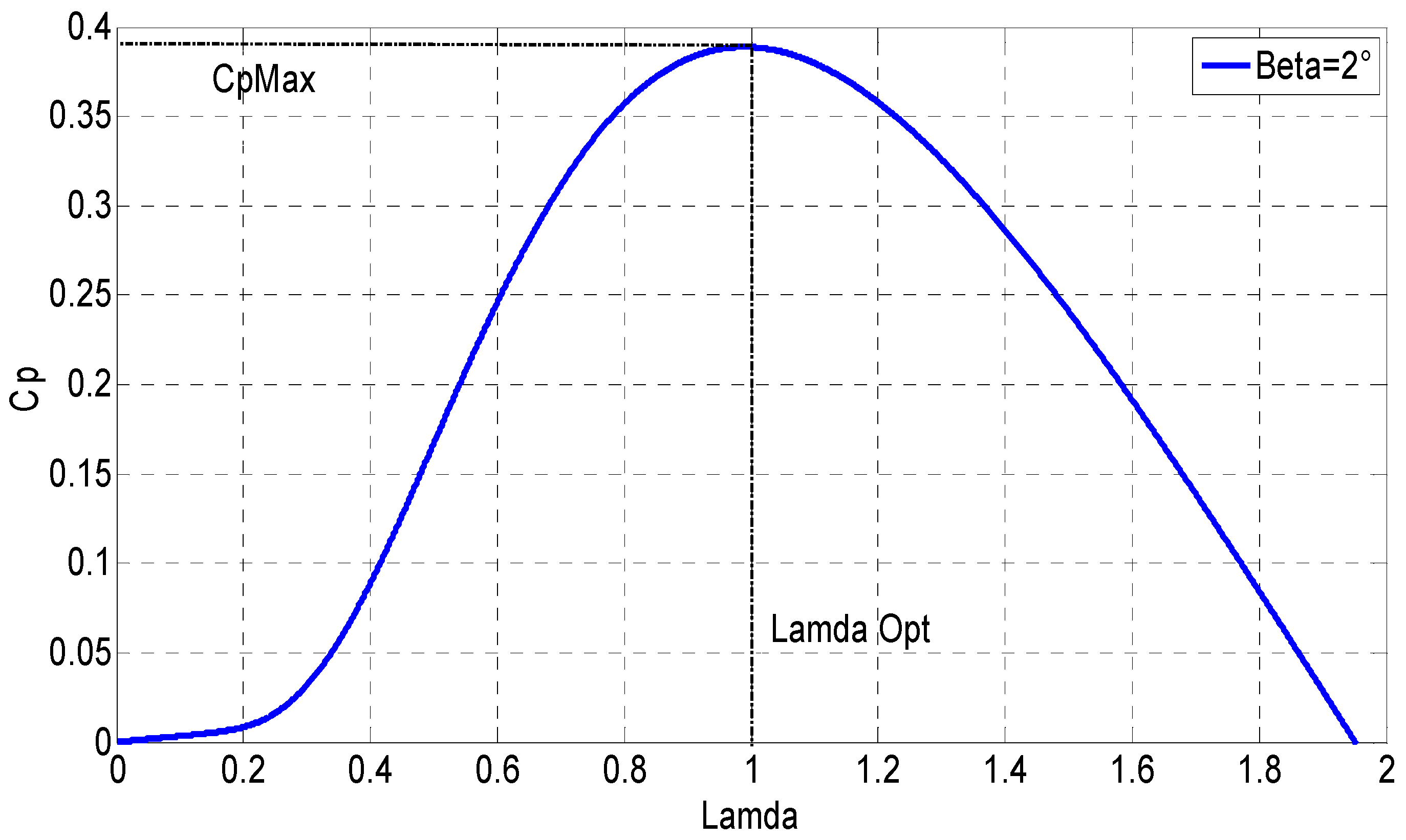
p = f (λ), as shown in
Figure 7, suffices to follow the optimal power curve
. So, the wind turbine is in the optimal conditions where λ = λ
opt and T
em =
.
In this work, the optimal torque-based MPPT was used as it is suitable for coupling with the torque control strategy of the SRG. The less conventional consider that the characteristic Cp = f (λ) is unknown. In this case, the MPPT estimates the optimal torque from the inverse model of the wind turbine.
The optimum value of the power coefficient is obtained for = 1 and Cp = 0.39.
As shown in
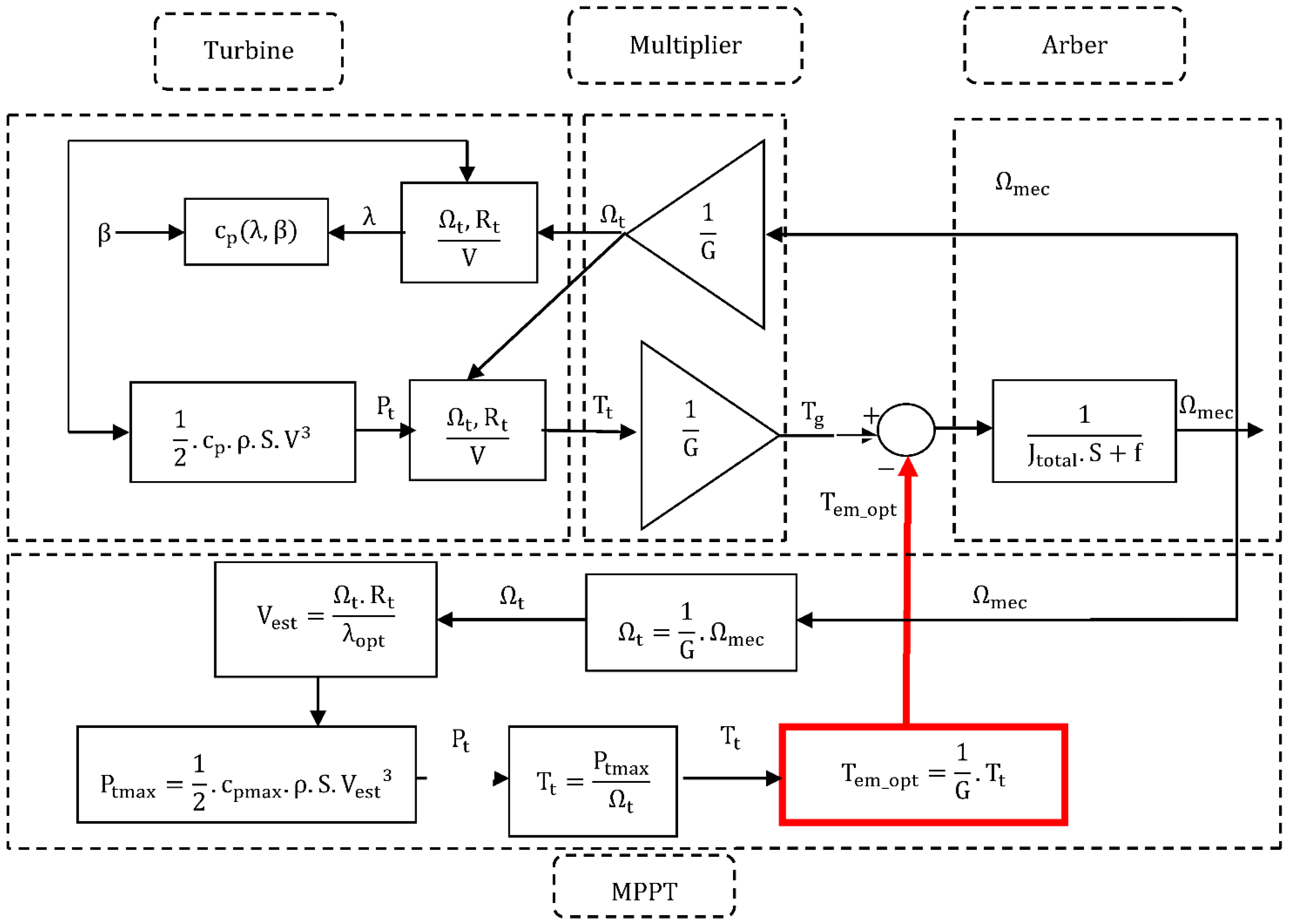
Figure 8, the MPPT control system must extract the maximum power
from the turbine; which is equivalent to finding the optimum rotation speed V
opt for wind speed; based on
and
and for maximum efficiency
. In the end, the optimal torque that has been found must be applied to the turbine to have the MPPT point [
24].
We note that the optimum value of the power coefficient is obtained for and Cp, equal, respectively, to 1 and 0.39.
Figure 8 depicts the manner of using the MPPT control system in order to obtain the maximum torque value, starting with Equations (5) and (8) to determine the optimum wind speed:
After determining the optimal value of the power factor C
p in conjunction with the optimal wind’s speed V
est, we obtain the maximum power for the turbine P
tmax and the aerodynamic torque:
After obtaining the turbine torque using Equation (14), the optimum torque T
g can be calculated and compared with the reference torque of the turbine; to get the optimum mechanical speed:
4. Overall Control Strategy
Most applications use an unbalanced bridge to control current within the hysteresis range. The asymmetric bridge allows three voltage states: +
, 0 and −
. So, depending on the control method, all these states are used to control the variable reluctance generator [
23,
36,
37]. Each state is independently controlled using a hysteresis or a PWM controller.
When switches T1 and T2 are closed, corresponding to the magnetization of the SRG (
Figure 9a), the voltage applied to phase 1 is the DC bus one (V = +
). When these switches are opened and diodes D1 and D2 are conducting, the applied voltage is reversed and becomes V = −
, which corresponds to the SRG generation (
Figure 9c). There is an intermediate supposedly freewheel sequence where switches T1 and diode D1 (or switches T2 and diode D2) are closed, leading to phase 1 short-circuit (V = 0,
Figure 9b).
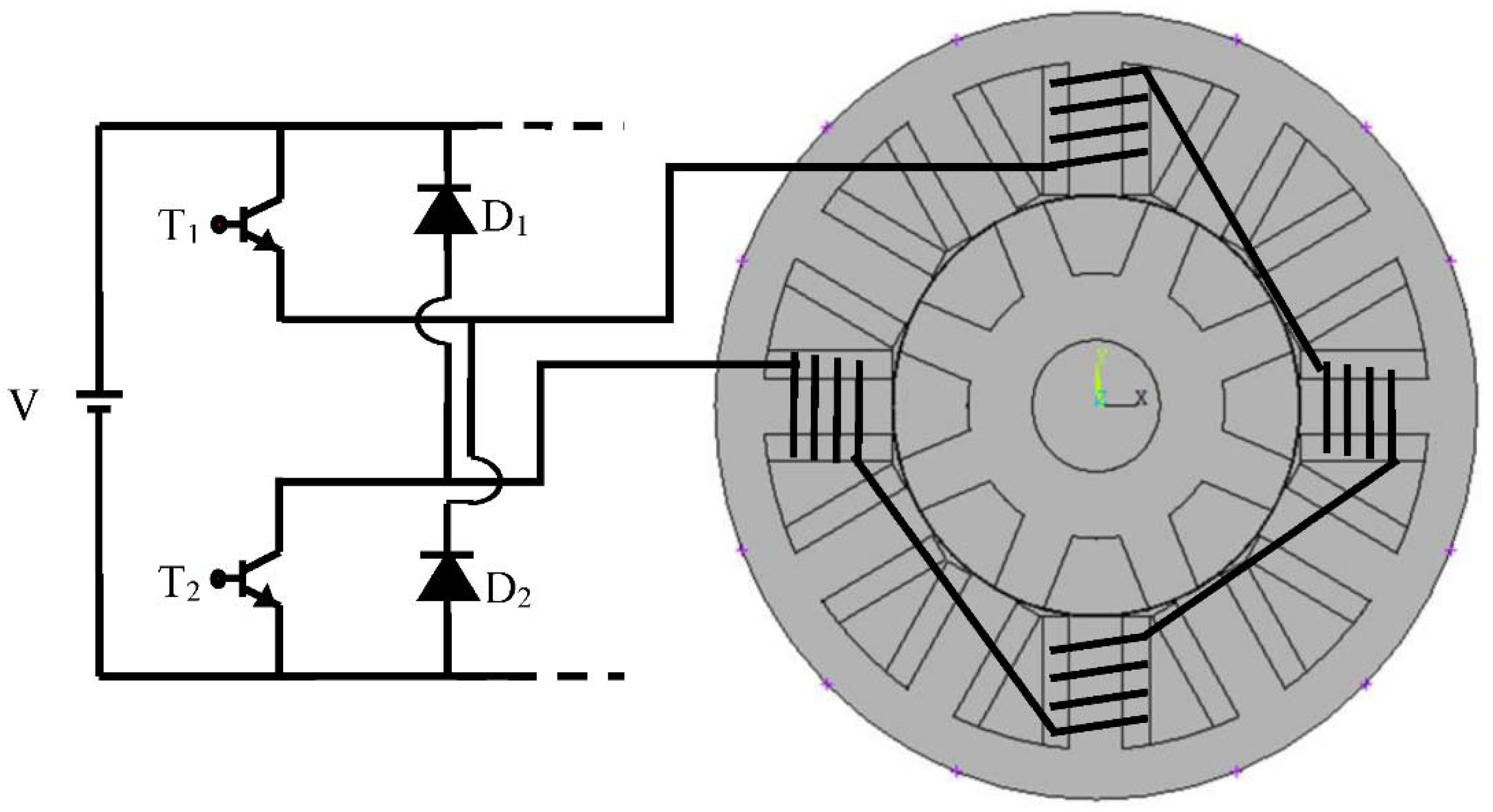
Figure 10 depicts the synoptic schema of the associated asymmetric bridge converter and our studied machine in order to explain the 12/8 SRM modeling steps.
The generator mode introduces a problem that does not exist in motor operation due to the back EMF (L < 0). Indeed, if the back EMF is greater than the DC bus voltage , then, the current is increasing when diodes D1 and D2 are conducting and there is no longer a configuration where the current is decreasing. As a result, the current increases without any control of the converter.
In order to generate current with an SRG, it is necessary to supply its phases when the inductance decreases. Indeed, in this region that the EMF is negative and will allow the generation of electric power. The increase in the speed Ω also works in favor of the flow possibilities, since it occurs in the previous expression of E (Equation (2)).
However, if we impose a square wave voltage across each phase, without chopping, we cannot control the current waveform. The only way to act on the latter is therefore to go through the two control angles: and .
Figure 10 shows the principle of operation in generator mode being fairly simple; its complexity lies in the control of the associated converter. In fact, the switching on (
) and the switching off (
) sequences must be well synchronized with the relative positions of the rotor-stator teeth (need for a position sensor) during the excitation phases and generation [
23,
37].
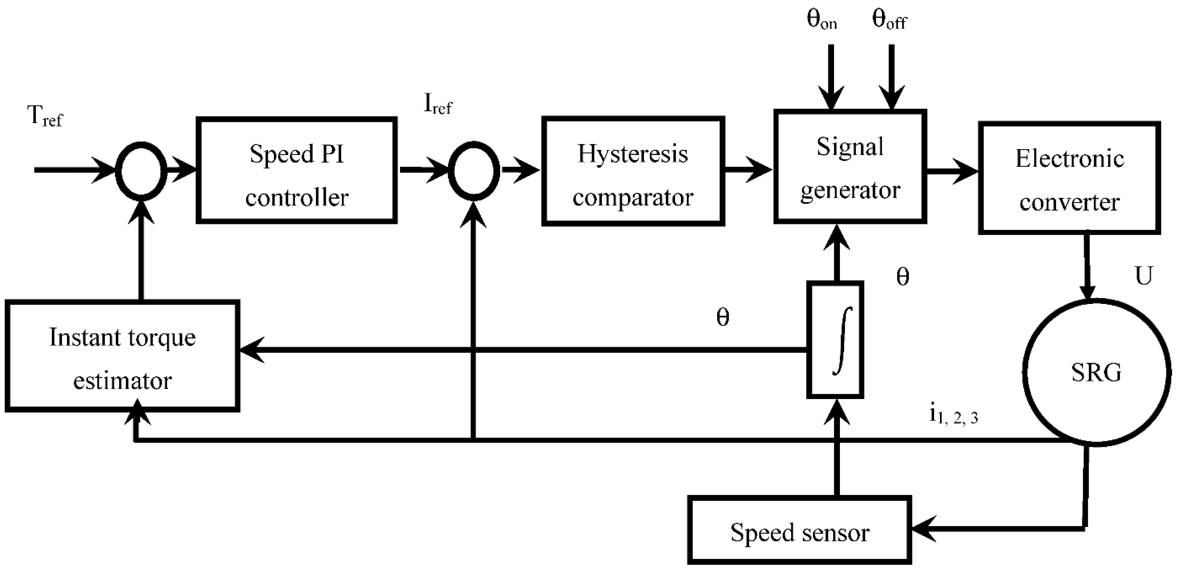
Each phase is independently controlled by a hysteresis control. The comparison between the desired torque and the measured one provides the reference current value thanks to a classic PI controller. The hysteresis control current HCC generates signals through the hysteresis comparator to have the measured current as reference current. The current must be controlled between the limits of the hysteresis band using a hard, soft, or hybrid switching strategy and between the limits of the switching angles:
and
. In the proposed control shown in
Figure 11, hard switching has been adopted.
5. Coupled HCC and Wind Turbine MPPT
Figure 12 shows a flowchart illustrating how to realize the combination of HCC-based indirect torque control with MPPT optimal torque IPC.
From the previous flowchart, the closed-loop torque control of the HCC while developing its association with the MPPT turbine and with the SRG was constructed as shown in
Figure 13.
In this control method, the MPPT generates a reference torque signal that represents the optimal torque for maximum power. The estimated torque signal is compared to the processing reference torque using a PI controller.
The speed controller generates the current value necessary to ensure equality between the measured torque and the reference one. So, the speed will not be controlled.
The required current is taken as a reference for the HCC control loop. In this loop, the amount of current, in the generator phase coil, is directly measured and compared to the reference current in order to determine the fault. The current error is compensated by the switching strategy used by the hysteresis comparison. As a result, the hysteresis current comparator generates status signals for all activation phases based on the current error. The signal generator is combined with phase switch boxes that depend on the switching angles for phase on, phase off, and demagnetization.
To control the switching signals: (, ), they are routed to the electronic transformer.
The mechanism of the HCC control system gives logical steps to have a reference torque by controlling the electric current. Namely, without speed control. This is due to the importance in this operation of the electromagnetic torque for maximum power, whereas the speed will be generated automatically according to the mechanical equation.
6. Simulation Results
The hysteresis control current control is one of the effective techniques to reduce the desired torque in the SRG. The HCC control techniques are implemented for SRG 12/8 under different operating conditions. It is realized taking into account the importance of the control parameters, which are the switching angles for a speed corresponding to 1000 rpm.
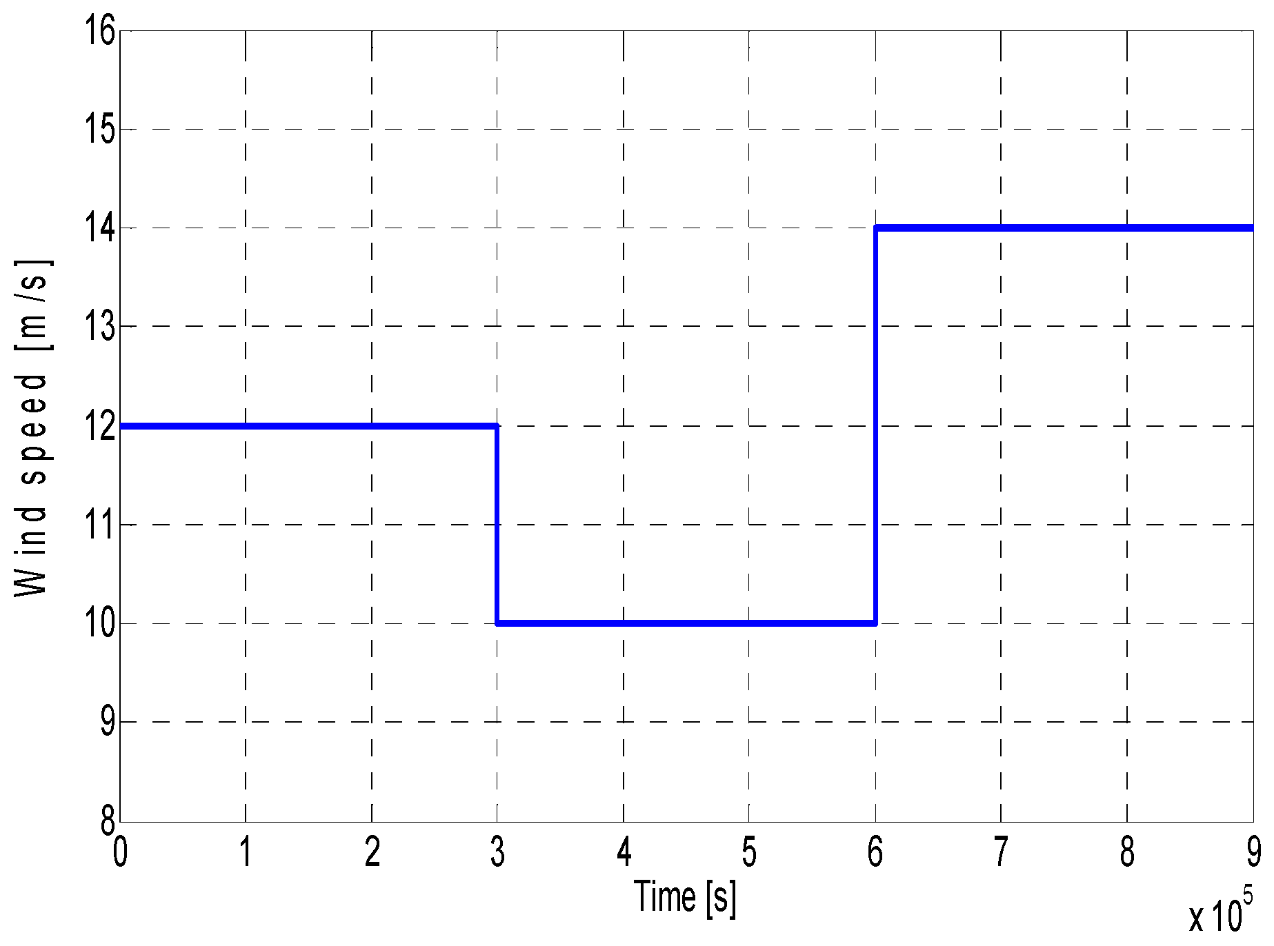
For the SRG-based wind turbine simulation, the turbine speed was considered to vary according to three levels as illustrated in
Figure 14. In this context, an uncontrolled simulation of the wind turbine is performed to study the system dynamic regime response using variable wind speed. In this test, the wind speed generator provides a wind speed of 12 m/s for a period from 0 to 3 s, 10 m/s for the period from 3 to 6 s, and a wind speed of 14 m/s for the period from 6 to 9 s (
Figure 14).
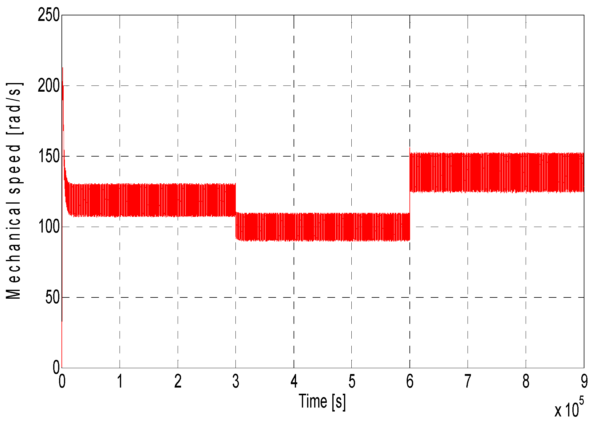
Figure 15 shows the SRG mechanical speed, where the increase in speed is obviously related to the increase in wind speed, resulting in an increase in generated power.
In what follows, the results will be treated with the variation of the switching angles: ( = 19°, = 38°) and ( = 22°, = 35°).
In
Figure 16 and
Figure 17, the supply voltage is obtained from the excitation battery and the electronic converter (the asymmetric bridge). Here, we have to realize a voltage adjustment according to the variation of the speed in order to ensure that the reference current matches the optimum reference torque so as to generate the maximum power from the turbine.
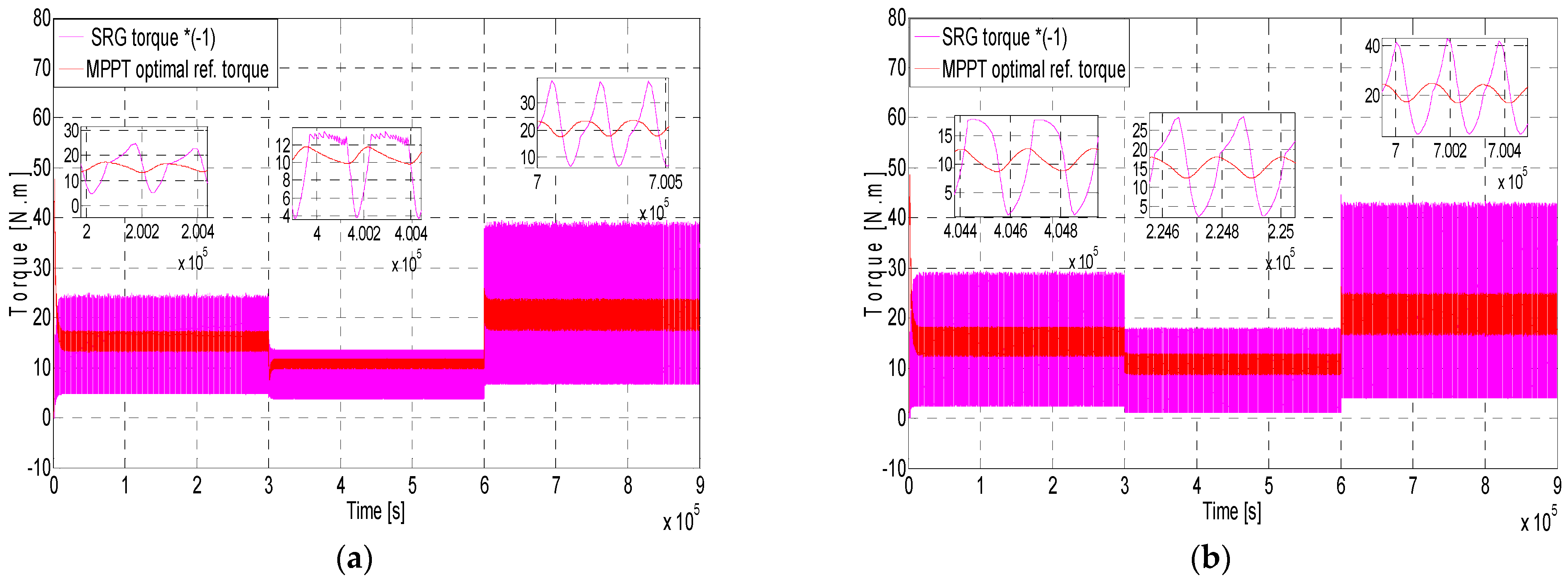
Figure 17 presents the SRG instantaneous torque response; according to the MPPT optimal reference torque for two cases of switching angles. Torque ripples present in
Figure 17b are less than those shown in
Figure 17a. It becomes clear that it is important to choose the appropriate switching angles, in order to achieve better performance. In addition, ripples reduction offers benefits in terms of improved noise and vibration performance, and increases the useful life of the generator.
Figure 18 shows the wind turbine power coefficient curves. Although the average efficiency of such a wind turbine is normally between 20% and 40%, it varies greatly with wind speed. The mechanical efficiency of the wind turbine is the highest (39% in this case) according to the profile given in
Figure 14. Here, the control system we propose is realized with the aim of maximizing the efficiency of the wind turbine system independently of the wind speed.
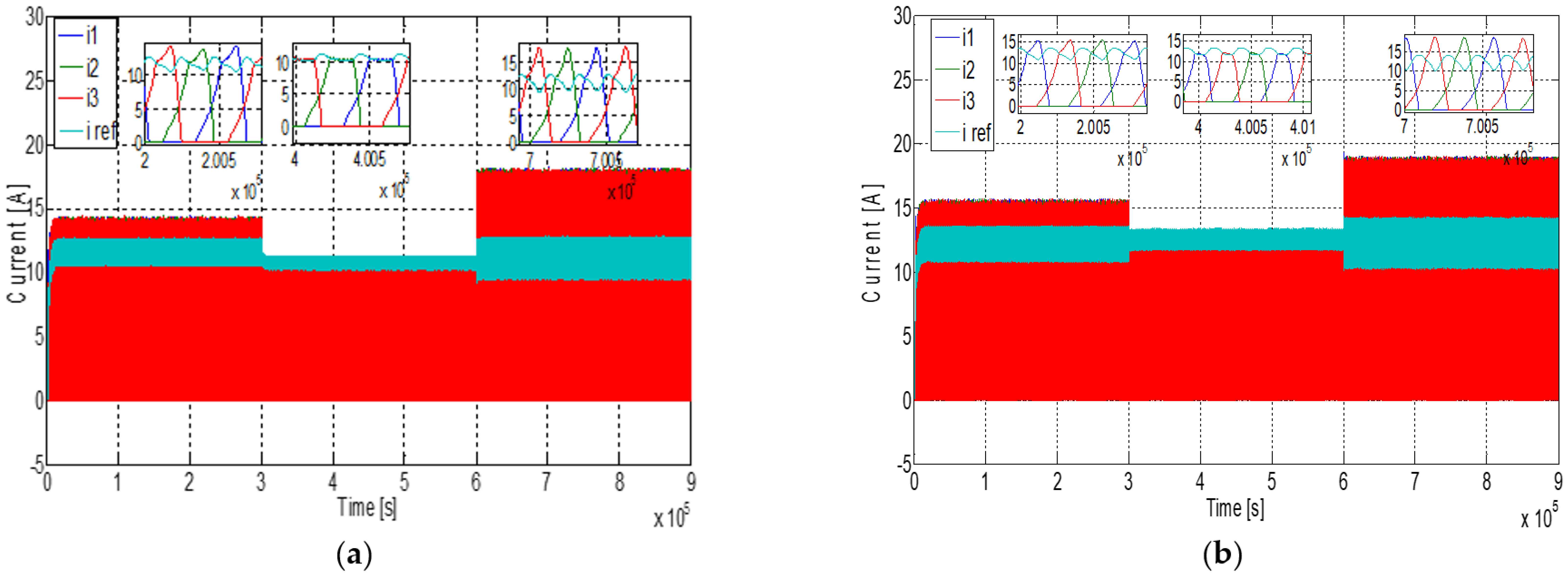
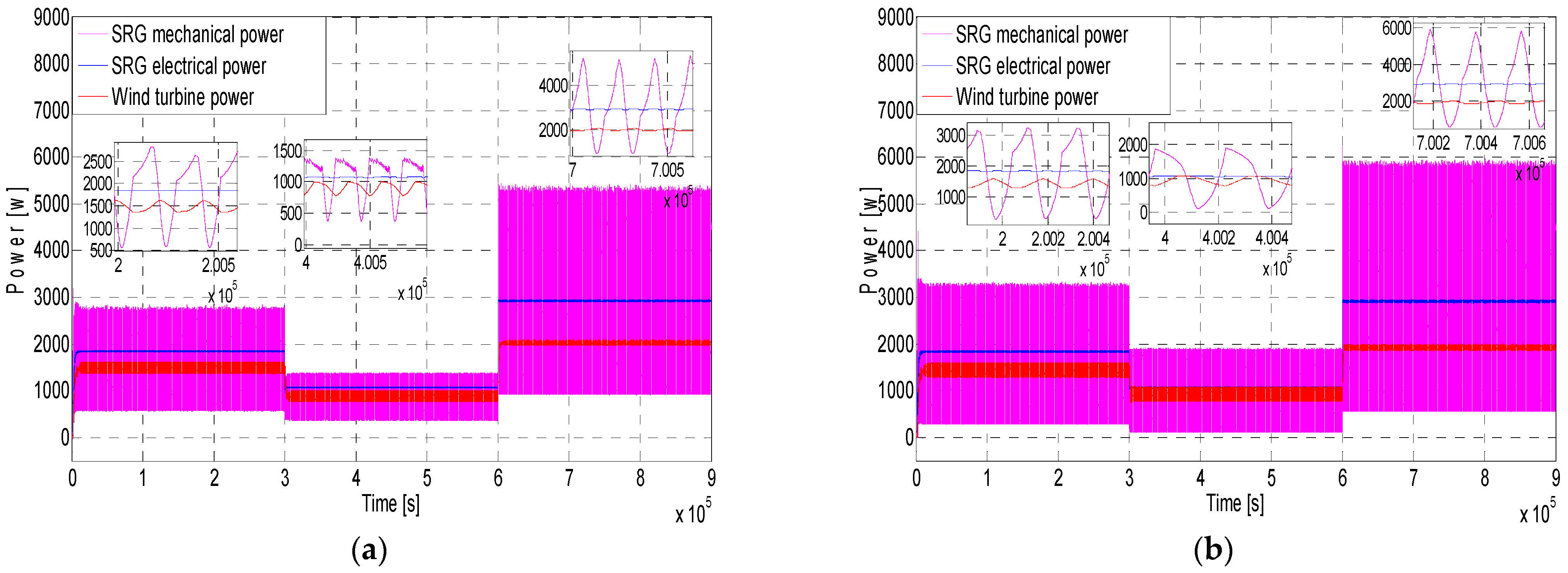
Figure 19 and
Figure 20 show, respectively, the hysteresis-controlled current and the different output powers curves for different wind speeds and switching angles: (
= 19°,
= 38°) and (
= 22°,
= 35°). The impact of changing switching angles on torque performance, current, energy efficiency and power quality have been clearly shown. In addition, MPPT importance has been also highlighted. Indeed, comparing cases of switching angles (
= 19°,
= 38) and (
= 22,
= 35°), as shown in
Figure 17 and
Figure 18, we can observe that power coefficient C
p oscillations or torque ripples are clearly decreased in the case where (
= 19°,
= 38°) compared to the case where (
= 22°,
= 35°). Accordingly, it becomes necessary to search for appropriate algorithms to determine the correct control parameters in real time for optimal performance.
7. Conclusions
This paper has proposed an indirect torque control and a maximum power point tracking technique for a 12/8 switched reluctance generator-based wind turbine in order to optimize the overall performance.
The MPPT IPC, based on the optimal torque using the wind turbine models, was used for its ability to be combined with the SRG torque control. The SRG model is based on the finite element method. The hysteresis control current strategy of the switched reluctance generator was used to control the instantaneous torque indirectly using an asymmetric bridge converter. The technique of combining the indirect torque control of 12/8 SRG by HCC with the MPPT IPC, based on the optimum torque, was used as a reference in the ITC in order to give the optimum power coefficient performance of the wind turbine.
Extensive simulations were carried out simultaneously considering the MPPT technique and different physical conditions, such as wind speed and the switching angles () variations. The achieved results clearly highlight the SRG-based wind turbine control performance while illustrating the important impact of the switching angles on the operational performance and the quality of the produced energy by the switched reluctance generator.
In terms of perspectives, future research should be directed towards the development of appropriate algorithms to determine the correct control parameters in real time for optimal performance. For experimental validation purposes, a lab-scale testbed is being developed.
Author Contributions
Conceptualization, M.Z., A.C. and C.L.; methodology, M.Z., A.C., C.L., M.I., K.S. and M.B.; software, M.Z., A.C. and C.L.; validation, M.Z., A.C., C.L., M.I., K.S. and M.B.; formal analysis, M.Z., A.C., C.L., M.I., K.S. and M.B.; investigation, M.Z., A.C. and C.L.; writing—original draft preparation, M.Z.; writing—review and editing, M.Z., A.C., C.L., M.I., K.S. and M.B. All authors have read and agreed to the published version of the manuscript.
Funding
This research received no external funding.
Institutional Review Board Statement
Not applicable.
Informed Consent Statement
Not applicable.
Data Availability Statement
Not applicable.
Conflicts of Interest
The authors declare no conflict of interest.
References
- Rahmanian, E.; Akbari, H.; Sheisi, G.H. Maximum power point tracking in grid connected wind plant by using intelligent controller and switched reluctance generator. IEEE Trans. Sustain. Energy 2017, 8, 1313–1320. [Google Scholar] [CrossRef]
- Dos Santos Barros, T.A.; dos Santos Neto, P.J.; Nascimento Filho, P.S.; Moreira, A.B.; Ruppert Filho, E. An approach for switched reluctance generator in a wind generation system with a wide range of operation speed. IEEE Trans. Power Electron. 2017, 32, 8277–8292. [Google Scholar] [CrossRef]
- García-Tabarés, L.; Laos, M.; Blanco, M.; Torres, J.; Orators, D.; Nájera, J.; Sánchez, A. New type of linear switched reluctance generator for wave energy applications. IEEE Trans. Appl. Supercond. 2020, 30, 1–5. [Google Scholar] [CrossRef]
- Chen, H.; Xu, D.; Deng, X. Control for power converter of small-scale switched reluctance wind power generator. IEEE Trans. Ind. Electron. 2021, 68, 3148–3158. [Google Scholar] [CrossRef]
- Sun, X.; Wan, B.; Lei, G.; Tian, X.; Guo, Y.; Zhu, J. Multiobjective and multiphysics design optimization of a switched reluctance motor for electric vehicle applications. IEEE Trans. Energy Convers. 2021, 36, 3294–3304. [Google Scholar] [CrossRef]
- Kushwaha, A.; Kanagaraj, R. Peak-current estimation using simplified current-rise model of switched reluctance generator operating in single-pulse mode. Int. J. Electr. Power Energy Syst. 2020, 120, 105971. [Google Scholar] [CrossRef]
- Omac, Z.; Cevahir, C. Control of switched reluctance generator in wind power system application for variable speeds. Ain Shams Eng. J. 2021, 12, 2665–2672. [Google Scholar] [CrossRef]
- Dranca, M.A.; Radulescu, M.M.; Petreus, D. Design and Control of a Direct-Driven Three-Phase Switched Reluctance Generator for Micro-Wind Power Applications. In Proceedings of the 12th International Symposium on Advanced Topics in Electrical Engineering (ATEE), Bucharest, Romania, 12 May 2021. [Google Scholar]
- Gameiro, N.S.; Cardoso, A.J.M. A new method for power converter fault diagnosis in SRM drives. IEEE Trans. Ind. Appl. 2011, 48, 653–662. [Google Scholar] [CrossRef]
- Nakamura, K.; Ichinokura, O. Super-multipolar permanent magnet reluctance generator designed for small-scale wind-turbine generation. IEEE Trans. Magn. 2012, 48, 3311–3314. [Google Scholar] [CrossRef]
- Cheng, H.; Wang, L.; Xu, L.; Ge, X.; Yang, S. An integrated electrified powertrain topology with SRG and SRM for plug-in hybrid electrical vehicle. IEEE Trans. Ind. Electron. 2019, 67, 8231–8241. [Google Scholar] [CrossRef]
- Diao, K.; Sun, X.; Lei, G.; Guo, Y.; Zhu, J. Multimode optimization of switched reluctance machines in hybrid electric vehicles. IEEE Trans. Energy Convers. 2020, 36, 2217–2226. [Google Scholar] [CrossRef]
- Han, S.; Cui, S.; Song, L.; Chan, C.C. Electromagnetic Analysis and Design of Switched Reluctance Double-Rotor Machine for Hybrid Electric Vehicles. Energies 2014, 7, 6665–6688. [Google Scholar] [CrossRef]
- Klein-Hessling, A.; Hofmann, A.; De Doncker, R.W. Direct instantaneous torque and force control: A novel control approach for switched reluctance machines. In Proceedings of the IEEE International Electric Machines & Drives Conference (IEMDC), Coeur d’Alene, ID, USA, 10–13 May 2015. [Google Scholar]
- Labiod, C.; Srairi, K.; Mahdad, B.; Benchouia, M.T.; Benbouzid, M.E.H. Speed control of 8/6 switched reluctance motor with torque ripple reduction taking into account magnetic saturation effects. Energy Procedia 2015, 74, 112–121. [Google Scholar] [CrossRef][Green Version]
- Labiod, C.; Srairi, K.; Mahdad, B.; Benbouzid, M.E.H. A novel control technique for torque ripple minimization in switched reluctance motor through destructive interference. Electr. Eng. Jpn. 2018, 100, 481–490. [Google Scholar] [CrossRef]
- Pande, J.; Nasikkar, P.; Kotecha, K.; Varadarajan, V. A review of maximum power point tracking algorithms for wind energy conversion systems. J. Mater. Sci. Eng. 2021, 9, 1187. [Google Scholar] [CrossRef]
- Kumar, D.; Chatterjee, K. A review of conventional and advanced MPPT algorithms for wind energy systems. Renew. Sustain. Energy Rev. 2016, 55, 957–970. [Google Scholar] [CrossRef]
- Labiod, C.; Srairi, K.; Mahdad, B.; Dib, A.; Benchouia, M.T.; Benbouzid, M.E.H. Optimum performances for non-linear finite elements model of 8/6 switched reluctance motor based on intelligent routing algorithms. Adv. Electr. Electron. Eng. 2017, 15, 1–11. [Google Scholar] [CrossRef]
- Lan, Y.; Benomar, Y.; Deepak, K.; Aksoz, A.; Baghdadi, M.E.; Bostanci, E.; Hegazy, O. Switched reluctance motors and drive systems for electric vehicle powertrains: State of the art analysis and future trends. Energies 2021, 14, 2079. [Google Scholar] [CrossRef]
- Valencia, D.F.; Tarvirdilu-Asl, R.; Garcia, C.; Rodriguez, J.; Emadi, A. A review of predictive control techniques for switched reluctance machine drives. Part I: Fundamentals and current control. IEEE Trans. Energy Convers. 2020, 36, 1313–1322. [Google Scholar] [CrossRef]
- Reis, M.R.; Calixto, W.P.; Araújo, W.R.; Matias, C.A. Increasing efficiency of the switched reluctance generator using parametric regression and optimization methods. In Proceedings of the 18th International Scientific Conference on Electric Power Engineering (EPE), Kouty nad Desnou, Czech Republic, 17–19 May 2017. [Google Scholar]
- Sarr, A.; Bahri, I.; Berthelot, E.; Kebe, A.; Diallo, D. Switched Reluctance Generator for Low Voltage DC Micro-grid Operation: Experimental Validation. Energies 2020, 12, 3032. [Google Scholar] [CrossRef]
- Sunan, E.; Kucuk, F.; Raza, K.S.; Goto, H.; Guo, H.; Ichinokura, O. Torque ripple minimization and maximum power point tracking of a permanent magnet reluctance generator for wind energy conversion system. J. Renew. Sustain. Energy 2013, 5, 013114. [Google Scholar] [CrossRef]
- Ye, J.; Bilgin, B.; Emadi, A. An extended-speed low-ripple torque control of switched reluctance motor drives. IEEE Trans. Power Electron. 2014, 30, 1457–1470. [Google Scholar] [CrossRef]
- Labiod, C.; Bahri, M.; Srairi, K.; Mahdad, B.; Benchouia, M.T.; Benbouzid, M.E.H. Static and dynamic analysis of non-linear magnetic characteristics in switched reluctance motors based on circuit-coupled time stepping finite element method. Int. J. Syst. Assur. Eng. Manag. 2017, 8, 47–55. [Google Scholar] [CrossRef]
- Kazmi, S.M.R.; Goto, H.; Guo, H.J.; Ichinokura, O. A novel algorithm for fast and efficient speed-sensorless maximum power point tracking in wind energy conversion systems. IEEE Trans. Ind. Electron. 2011, 58, 29–36. [Google Scholar] [CrossRef]
- Tan, K.; Islam, S. Optimum control strategies in energy conversion of PMSG wind turbine system without mechanical sensors. IEEE Trans. Energy Convers. 2004, 19, 392–399. [Google Scholar] [CrossRef]
- Zhu, Y.; Cheng, M.; Hua, W.; Wang, W. A novel maximum power point tracking control for permanent magnet direct drive wind energy conversion systems. Energies 2012, 5, 1398–1412. [Google Scholar] [CrossRef]
- Koutroulis, E.; Kalaitzakis, K. Design of a maximum power tracking system for wind-energy-conversion applications. IEEE Trans. Ind. Electron. 2006, 53, 486–494. [Google Scholar] [CrossRef]
- Errami, Y.; Ouassaid, M.; Maaroufi, M. Optimal power control strategy of maximizing wind energy tracking and different operating conditions for permanent magnet synchronous generator wind farm. Energy Procedia 2015, 74, 477–490. [Google Scholar] [CrossRef]
- Castelló, J.; Espí, J.M.; García-Gil, R. Development details and performance assessment of a Wind Turbine Emulator. Renew. Energy 2016, 86, 848–857. [Google Scholar] [CrossRef]
- Ghaffari, A.; Krsti´c, M.; Seshagiri, S. Power optimization and control in wind energy conversion systems using extremum seeking. IEEE Trans. Control Syst. Technol. 2014, 22, 1684–1695. [Google Scholar] [CrossRef]
- Balasundar, C.; Sudharshanan, S.; Elakkiyavendan, R. Design of an optimal tip speed ratio control MPPT algorithm for standalone WECS. Int. J. Res. Appl. Sci. Eng. Technol. 2015, 3, 5. [Google Scholar]
- Mousa, H.H.; Youssef, A.R.; Mohamed, E.E. Variable step size P&O MPPT algorithm for optimal power extraction of multi-phase PMSG based wind generation system. Int. J. Electr. Power Energy Syst. 2019, 108, 218–231. [Google Scholar]
- Han, S.; Diao, K.; Sun, X. Overview of multi-phase switched reluctance motor drives for electric vehicles. Adv. Mech. Eng. 2021, 13, 168781402110451. [Google Scholar] [CrossRef]
- Chen, H.C.; Wang, W.A.; Huang, B.W. Integrated driving/charging/discharging battery-powered four-phase switched reluctance motor drive with two current sensors. IEEE Trans. Power Electron. 2018, 34, 5019–5022. [Google Scholar] [CrossRef]
Figure 1.
SRG diagram and associated converter for a wind power application.
Figure 1.
SRG diagram and associated converter for a wind power application.
Figure 2.
SRM operation principle.
Figure 2.
SRM operation principle.
Figure 3.
Flux density of the 12/8 SRM in extreme position for a current equal to 12 A: (a) Unaligned position; (b) Aligned position.
Figure 3.
Flux density of the 12/8 SRM in extreme position for a current equal to 12 A: (a) Unaligned position; (b) Aligned position.
Figure 4.
Inductance characteristics as a function of the rotor position for currents ranging from 2 to 16 A.
Figure 4.
Inductance characteristics as a function of the rotor position for currents ranging from 2 to 16 A.
Figure 5.
Static torque characteristics as a function of the rotor position for currents ranging from 2 to 16 A.
Figure 5.
Static torque characteristics as a function of the rotor position for currents ranging from 2 to 16 A.
Figure 6.
Power coefficient Cp as a function of the tip speed ratio λ and the pitch angle β.
Figure 6.
Power coefficient Cp as a function of the tip speed ratio λ and the pitch angle β.
Figure 7.
Variation of the power coefficient Cp with respect to the tip speed ratio λ for β = 2°.
Figure 7.
Variation of the power coefficient Cp with respect to the tip speed ratio λ for β = 2°.
Figure 8.
Block diagram of the MPPT power maximization of the wind turbine.
Figure 8.
Block diagram of the MPPT power maximization of the wind turbine.
Figure 9.
Possible states of the supply voltage for a phase of the SRG: (a) unaligned position voltage positive +Vcc: two switches are closed; (b) Voltage zero “0”: one switch is open and the other is closed; (c) Voltage negative −Vcc: two switches are closed.
Figure 9.
Possible states of the supply voltage for a phase of the SRG: (a) unaligned position voltage positive +Vcc: two switches are closed; (b) Voltage zero “0”: one switch is open and the other is closed; (c) Voltage negative −Vcc: two switches are closed.
Figure 10.
Synoptic schema of the 12/8 SRG associated with an asymmetric bridge converter.
Figure 10.
Synoptic schema of the 12/8 SRG associated with an asymmetric bridge converter.
Figure 11.
Proposed hysteresis control current with torque control loop.
Figure 11.
Proposed hysteresis control current with torque control loop.
Figure 12.
Global flowchart of the proposed association technique.
Figure 12.
Global flowchart of the proposed association technique.
Figure 13.
The HCC of the SRG associated with the wind turbine MPPT.
Figure 13.
The HCC of the SRG associated with the wind turbine MPPT.
Figure 14.
Adopted wind speed for simulation purposes.
Figure 14.
Adopted wind speed for simulation purposes.
Figure 15.
SRG mechanical speed.
Figure 15.
SRG mechanical speed.
Figure 16.
Supply voltage and electric current of the switched reluctance generator: (a) For and ; (b) For and .
Figure 16.
Supply voltage and electric current of the switched reluctance generator: (a) For and ; (b) For and .
Figure 17.
Optimal reference torque of the MPPT and the switched reluctance generator: (a) For and ; (b) For and .
Figure 17.
Optimal reference torque of the MPPT and the switched reluctance generator: (a) For and ; (b) For and .
Figure 18.
MPPT power efficiency of the wind turbine associated with the SRG: (a) For and ; (b) For and .
Figure 18.
MPPT power efficiency of the wind turbine associated with the SRG: (a) For and ; (b) For and .
Figure 19.
Current controlled by the hysteresis comparator for the three phases of the 12/8 SRG: (a) For: and ; (b) For: and .
Figure 19.
Current controlled by the hysteresis comparator for the three phases of the 12/8 SRG: (a) For: and ; (b) For: and .
Figure 20.
12/8 SRG and turbine powers using HCC control and MPPT: (a) For and ; (b) For: and .
Figure 20.
12/8 SRG and turbine powers using HCC control and MPPT: (a) For and ; (b) For: and .
Table 1.
Switched reluctance motor characteristics.
Table 1.
Switched reluctance motor characteristics.
| Characteristics | Values |
|---|
| SRM Ns/Nr | 12/8 |
| Polar arc of the stator βs | 15.28° |
| Polar arc of the rotor βr | 15.48° |
| Stator outer radius | 69.5 mm |
| Inside radius of stator cylinder head | 57.5 mm |
| Inside radius of stator | 37.5 mm |
| Air gap | 0.5 mm |
| Rotor outer radius | 37 mm |
| Rotor cylinder head outer radius | 24.5 mm |
| Shaft radius | 12.5 mm |
| Active length | 110 mm |
| Number of turns per pole | 50 |
| Publisher’s Note: MDPI stays neutral with regard to jurisdictional claims in published maps and institutional affiliations. |
© 2022 by the authors. Licensee MDPI, Basel, Switzerland. This article is an open access article distributed under the terms and conditions of the Creative Commons Attribution (CC BY) license (https://creativecommons.org/licenses/by/4.0/).

