1. Introduction
Robot formation control research has attracted interest due to advantages such as flexibility, adaptability, robustness, and cost reduction found in the idea of multiple robots working together on applications in areas such as rescue, transportation, mine sweeping, geographic exploration, surveillance, agriculture, and more [
1,
2,
3,
4]. One of the objectives behind this kind of collaborative control is to imitate the work of some biological systems [
2,
3,
4,
5].
Multiple works have been reported in the literature mainly based on leader-follower, behavior-based, and virtual structure schemes [
1,
2,
5]. Moreover, robot formation can be implemented with centralized or decentralized control [
2,
5]. The authors of [
1] propose a leader-follower formation control of multiple robots and transforming the prescribed performance into an unconstrained one. In [
5], the control of nonholonomic mobile robots with a leader-follower scheme is presented with simulation results. The study [
5] is based on linear approximation, feedback linearization, and known position of the leader, and the collision algorithm is based on priorities. Study [
6] shows a behavior-based algorithm for forming patterns based on swarm intelligence. In [
7], a leader-follower approach and collision avoidance scheme based on a virtual leader is presented. In [
8], a distributed control law is used to achieve circular and non-circular formation for multiple robots.
The works mentioned above and our proposed scheme use the robot’s different sensors to access information such as the position of the robot, detection of obstacles, and communication. We encourage the reader to look for the references mentioned in those works.
On the other hand, a complex network can be defined as a system made of many single units which, from the perspective of dynamical systems, are systems on their own, interacting in such a way that the behavior of the whole system is not just the sum of the behaviors of the single units [
3,
4,
9]. Complex networks can be found in many fields, such as engineering, physics, technology, biology, and social sciences, to name a few.
Moreover, a complex network has characteristics such as a better representation of real-world complex systems with nontrivial structures. They are dynamic, and their nodes can be dynamic systems. Moreover, they can be structurally complex, among other things [
3,
4,
9].
In previous works [
10,
11], pinning control methodology was used to stabilize complex networks; this approach consists of controlling just some of the nodes in the network. The results of these previous works motivate the idea of pinning control for the formation of mobile robots. In this way, it is only necessary to design the position control for just one of the node robots of the network, meaning that only one knows the final position. This is an advantage when adding more nodes or if the position control strategy is thought to be changed in the future.
It is important to remark that the selected node is known as the pinned node; this is the reason why it is called pin control. It has a similar function as a leader in a leader-follower approach. However, it is not a leader; it may receive information from other nodes in the network, but in the leader-follower approach, the leader does not receive information from other nodes. The proposed formation control based on pin control of complex networks has the following characteristics: the formation is achieved through synchronizing the designed complex network, where a node is selected as the pinned control node, and the formation is achieved on a set point which is only known by a selected robot as a pinned node, and just a set number of the remaining robots are connected to it. Collison avoidance is assured against other robots and objects, not only between robots; a mounted LiDAR (light detection and ranging) sensor obtains the distances between a robot and any object. Simulation and experimental test results are included in this work using a different number of robots per test. Tests ended at the desired position in the desired formation. In contrast to previous works that use the robot’s known position to avoid a collision, this work uses the mounted LiDAR on the selected Turtlebot3® robots.
The remainder of this work is organized as follows.
Section 2 briefly introduces the complex network model and control methodology, along with the model of the mobile robots used in the implementation. In
Section 3, the proposed control scheme based on complex networks and pinning control is presented. The implementation of the proposal and the results of the tests are presented in
Section 4.
Section 5, the results discussion, gives a brief analysis of the obtained results and includes a comparison against other techniques. Finally, respective conclusions are given in
Section 6.
3. Proposed Scheme for Formation Control of Differential Robots
The objective of the control is to make formations with distinct sets of differential robots. For this, we define
as a sum of three terms, that is:
These terms will be defined as follows. First,
is:
where the terms are defined as in
Section 2.1. This has the form
which is the term describing the connections of the complex network model (1). After this, we can take the pinning control concept of complex networks and apply it here by adding the control term
defined in (2).
As seen in multiple works [
10,
11,
12,
13], with pinning control, all nodes synchronize to the same state; however, robots cannot physically be in the same space as another robot, so a translation of coordinates is necessary to simulate that they are synchronizing in the same state as the other robots, and
becomes
where
with
and
is the distance between robots
and
in the
and
axis, respectively, in a given final formation.
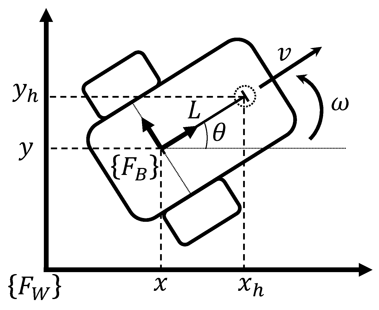
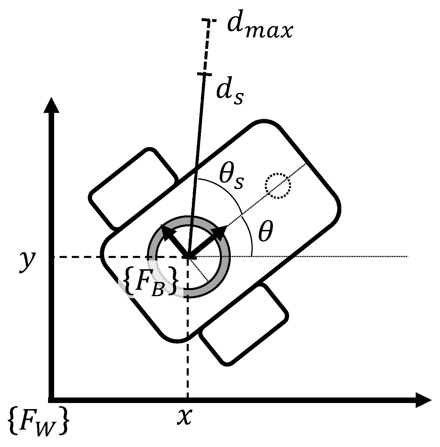
To avoid robot collisions, a LiDAR sensor is attached to the base frame
at the position
of each mobile robot as seen in
Figure 2. This sensor provides the current range data
at the angular position
, both measured from base frame
. Moreover,
is the maximum range value for detection. From these measurements, the repulsion term
is proposed as follows:
where
is a positive gain. The orientation
of robot
is considered to compute repulsion
relative to the world frame
.
Then, defining
we find
which is the complex network model of (1) with
and a coordinate translation in the connections.
4. Simulation and Physical Implementations
This section presents the details of implementing the proposed collaborative control scheme for mobile robots at the simulation and experimental levels using Gazebo software and Turtlebot3® Waffle Pi robots. Such implementation in both scenarios was held using Python and ROS (Robot Operating System) environments.
4.1. Experiment Description
To implement the proposed scheme, we used Turtlebot3® Waffle Pi robots. Among the hardware elements of a Turtlebot3® Waffle Pi robot, it has a Raspberry Pi 3, actuators XL430-W20, LiDAR sensor 360 laser Distance Sensor LDS-01, IMU with gyroscope 3 axis, and accelerometer 3 axis. The robot pose is calculated by the robot giving an odometry ROS message with its position and orientation. It is important to note that the accuracy of this measurement varies in function of the terrain conditions and wear of the robot equipment.
The LiDAR sensor is used to detect near objects. The LiDAR sensor obtains the necessary values to compute of Equation (13). This scheme was tested first in the Gazebo simulation environment using arrays of 4, 6, and 12 robots. Only one of the robots was a pinned node in all configurations, and all coordinates and distances are in meters.
4.1.1. Simulation Test: 4 Robots
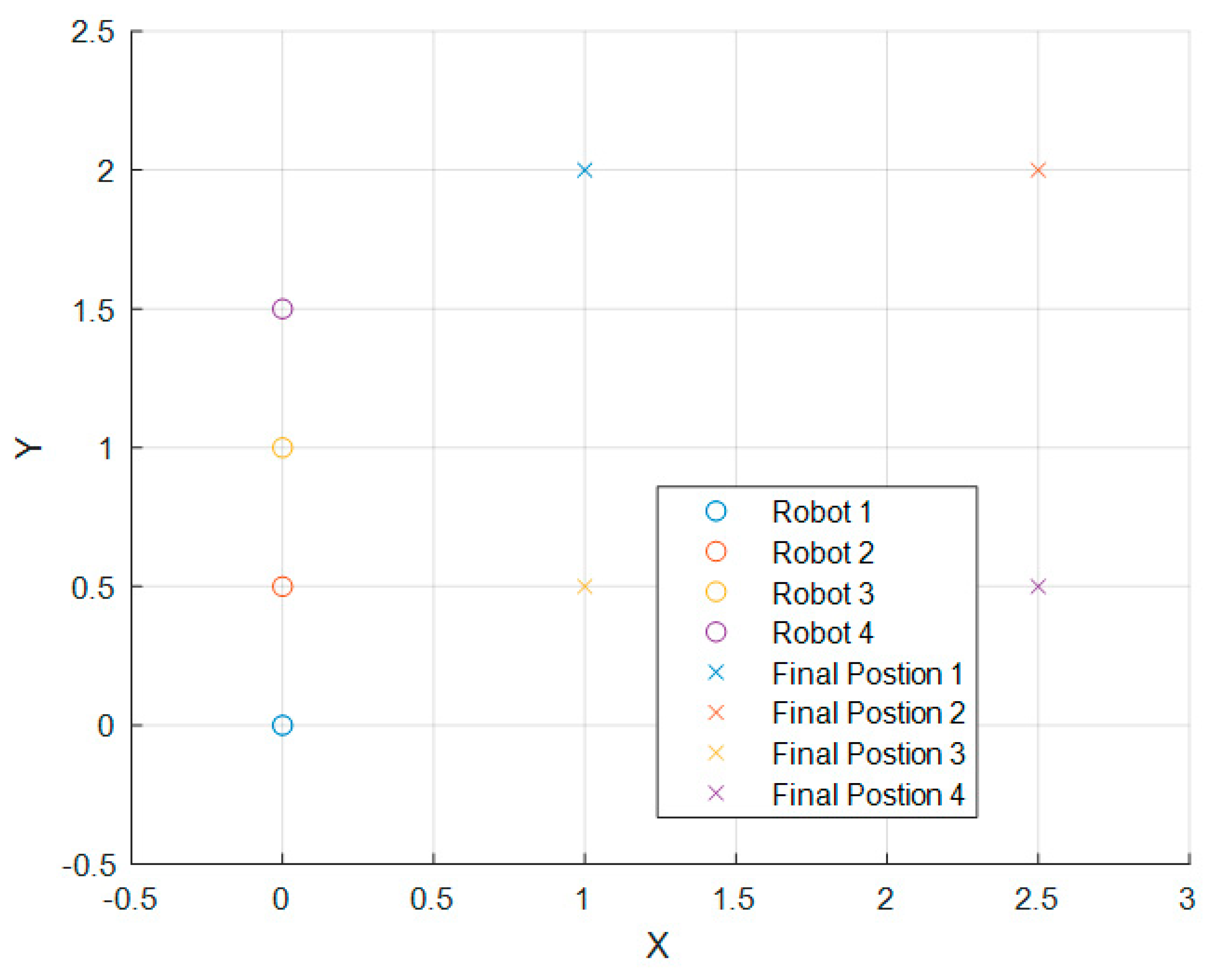
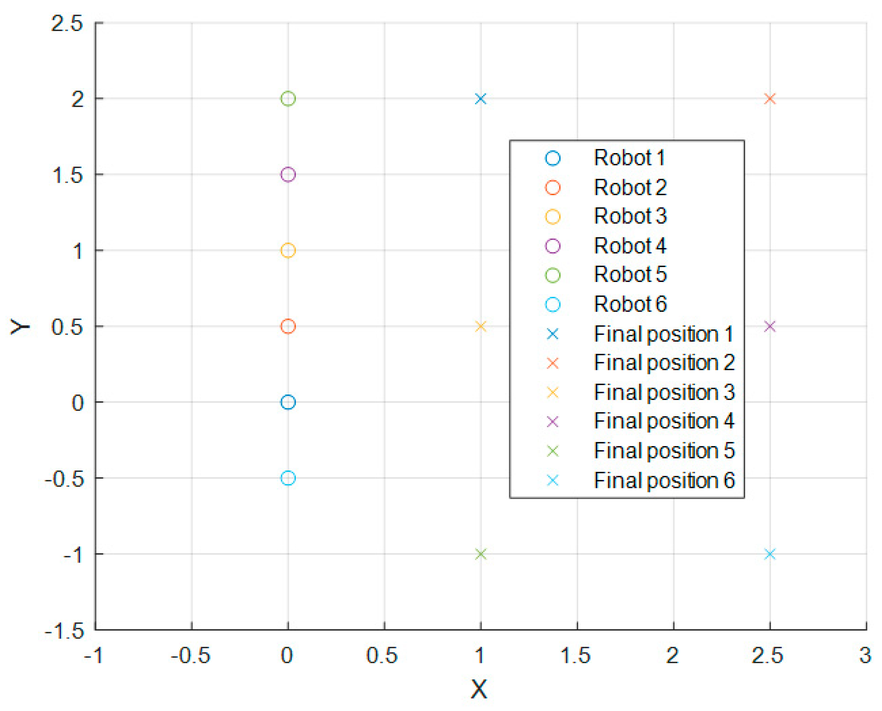
The initial positions in the 4-robot simulation and their objectives are illustrated in
Figure 3.
If we define
, then, in the 4-robot simulation,
can be obtained from the matrix:
where values were heuristically determined,
is an identity matrix, and
can be obtained from
Table 1, where
.
Using this, we can compute
, which will be scaled as
with
For
and for
,
and
. The
condition exists so that the control algorithm gives priority to evading obstacles. Finally, the computed
and
are scaled or saturated under certain conditions. Using a
, if computed that
then it is multiplied by a factor
; if by doing this
still exceeds
then we equate them. Similarly, with computed
, using a
and a factor
. This was done in order to not exceed the physical limitations of the robot and to not saturate the control signal of the robots all the time. The value of parameter
of Equation (7) was set as
.
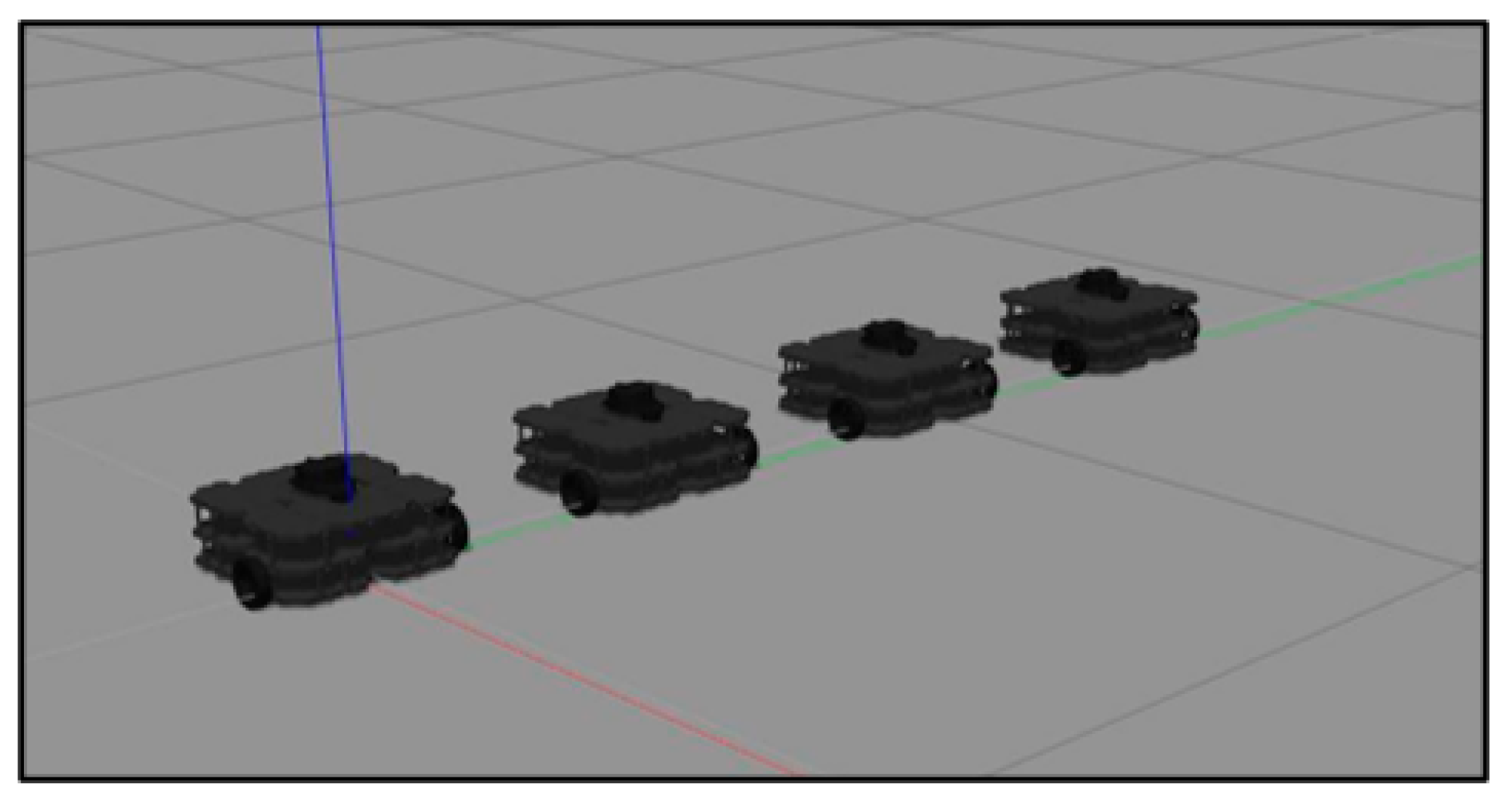
Figure 4 shows the Gazebo simulation environment and the robots’ initial position for the 4-robot simulation tests.
4.1.2. Simulation Test: 6 Robots
The initial positions for the 6-robot simulation and their objectives are illustrated in
Figure 5.
In this simulation,
is defined as follows for a six-robot configuration:
and
can be obtained from
Table 2.
Any other parameters stayed as in the previous simulation for 4 robots.
4.1.3. Simulation Test: 12 Robots
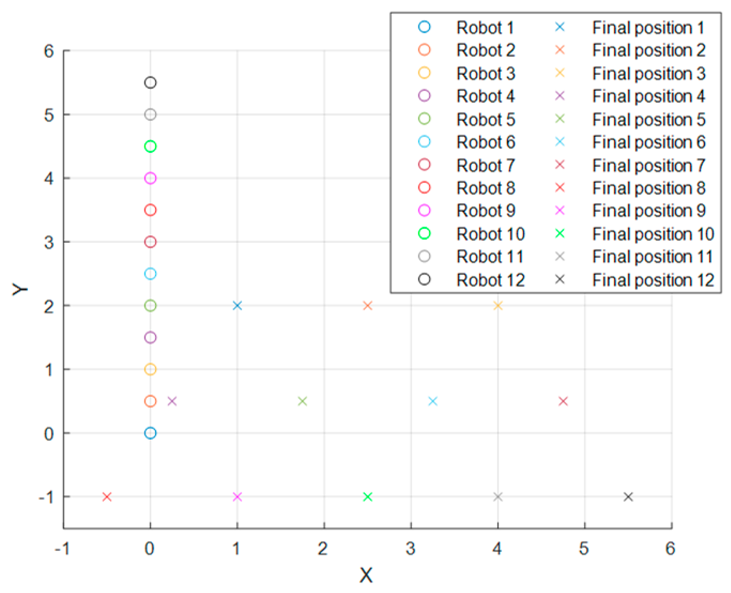
The initial positions for the 12-robot simulation and their objectives are illustrated in
Figure 6.
Any other parameters stayed as in the previous presented simulations.
Note that all the tables presented in this section are in accordance with the formation distances shown in
Figure 3,
Figure 5 and
Figure 6, respectively.
After simulations, the 4- and 6-robot arrays were tested with real equipment with the same set of parameters.
4.2. Experiment Results
This section shows the results of the simulation and experimental test using Turtlebot3® Waffle Pi robots. The results of tests with 4 and 6 robots are compared to the experimental implementation on the physical hardware. The results of the 12 robot tests were left at simulation level.
First, we present the data results of the Gazebo implementations.
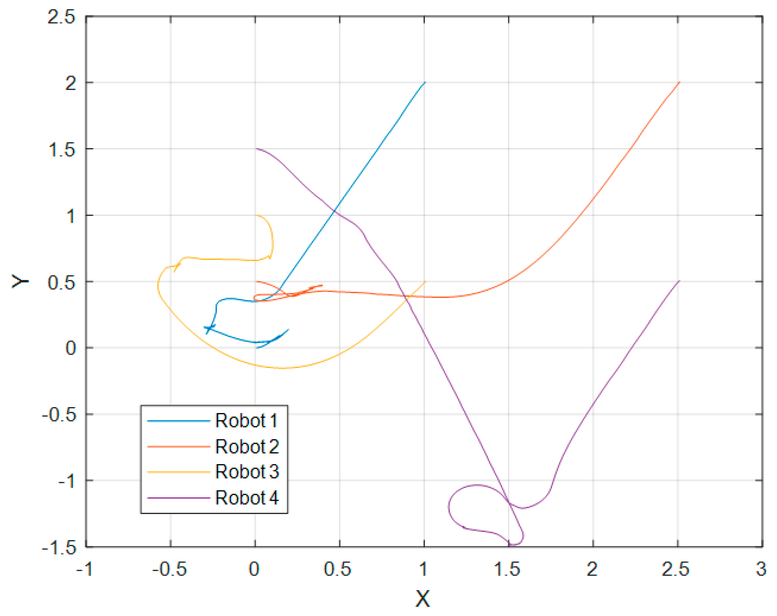
Figure 7 shows the trajectory followed by each robot on a 4-robot array in the Gazebo simulation test in the XY plane.
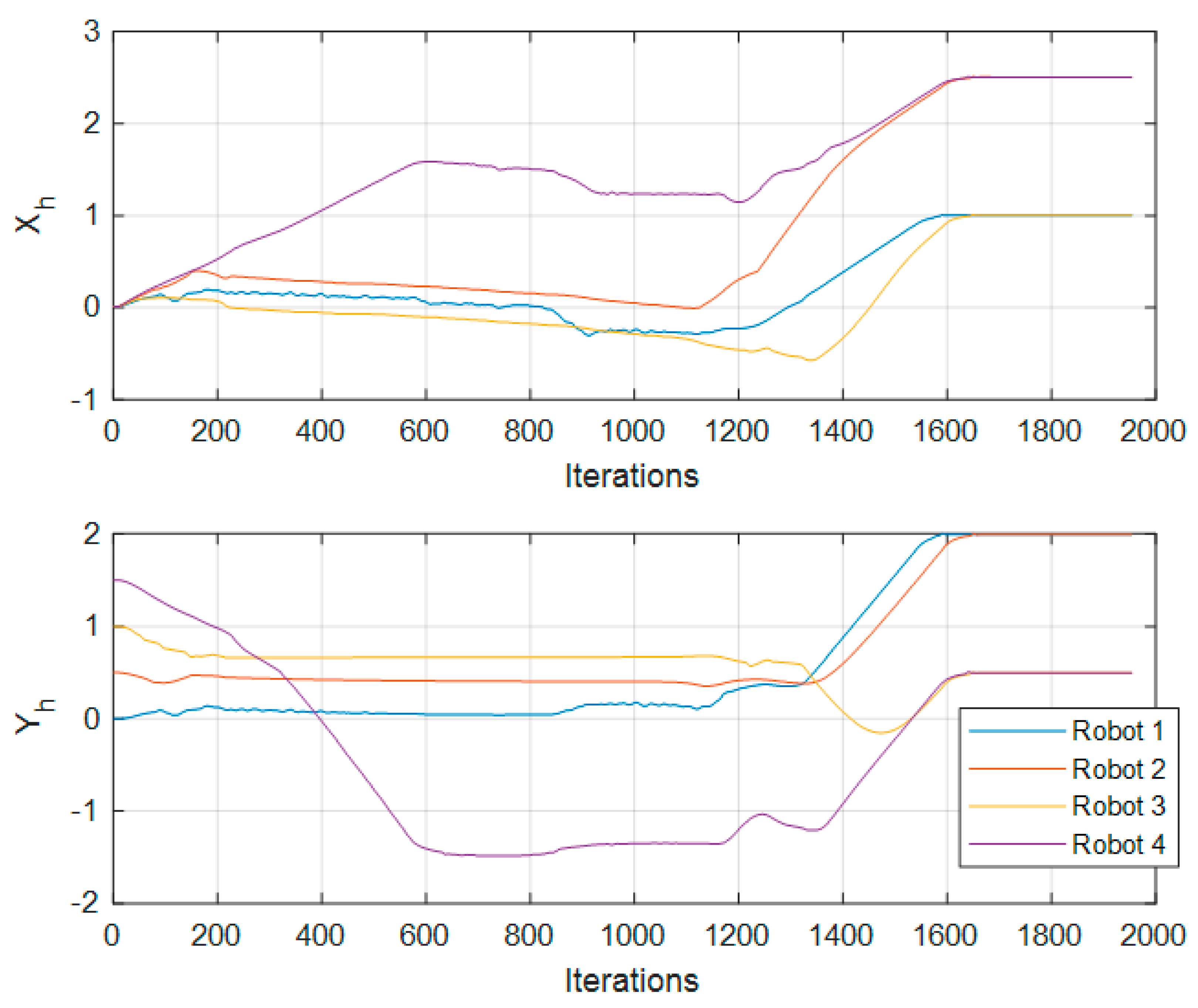
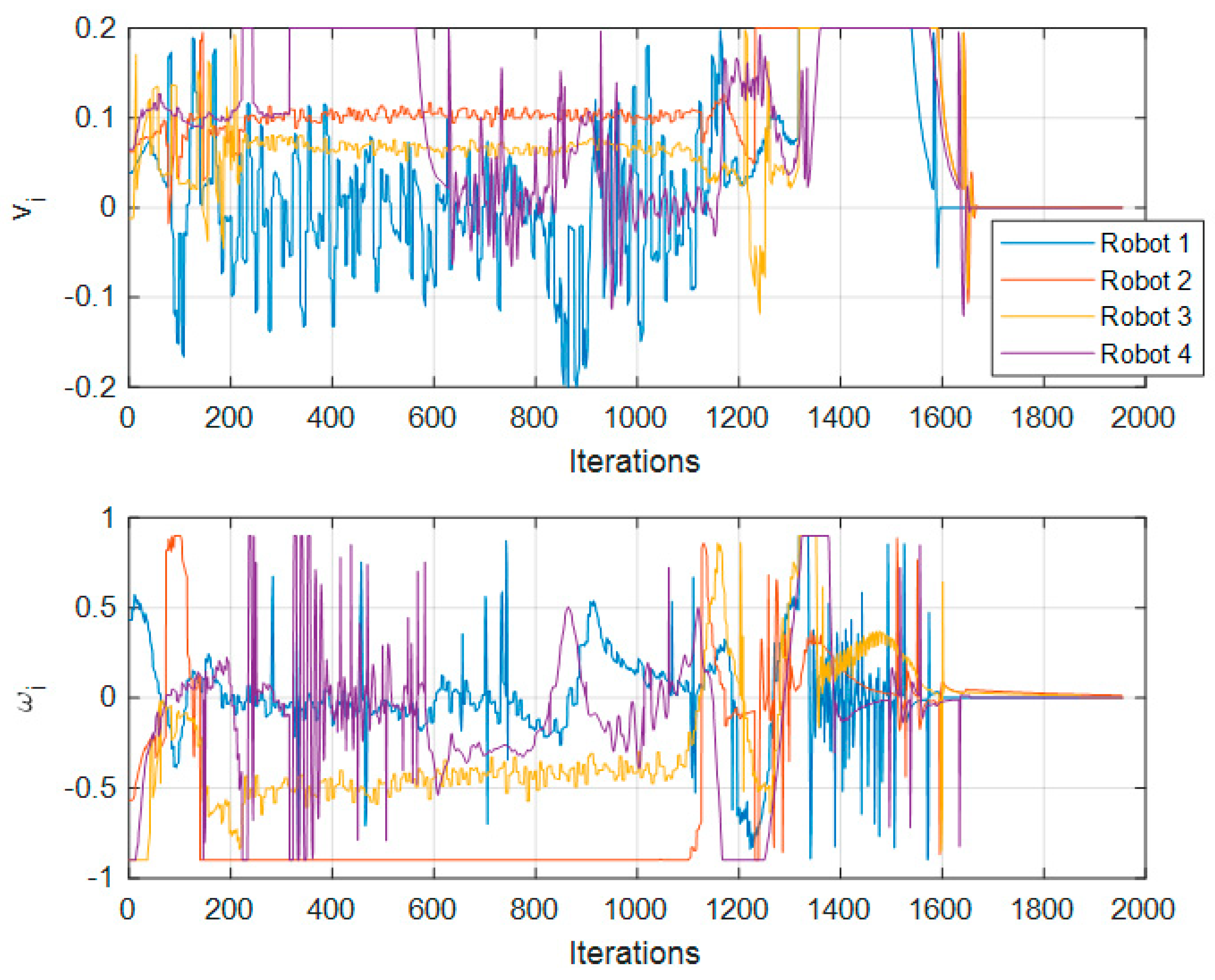
The values of
,
,
, and
through the iterations are plotted in
Figure 8 and
Figure 9.
In this test, 1000 iterations are roughly equivalent to 40 s with computer equipment with the following characteristics: Intel® Core™ i7-4770 CPU @3GHz under Ubuntu 16.04 operative system.
In
Figure 7 it is observed that the robots go to the desired position, trying to maintain the formation as they advance to the objective; that is why Robot 4 goes far down the
Y axis before positioning itself in its objective, as that is its place in respect to the other robots. We can also see a few oscillatory movements which are the result of the repulsion input term. In
Figure 8, we can observe no collision between robots. These observations can also be made in the corresponding Figures for each test.
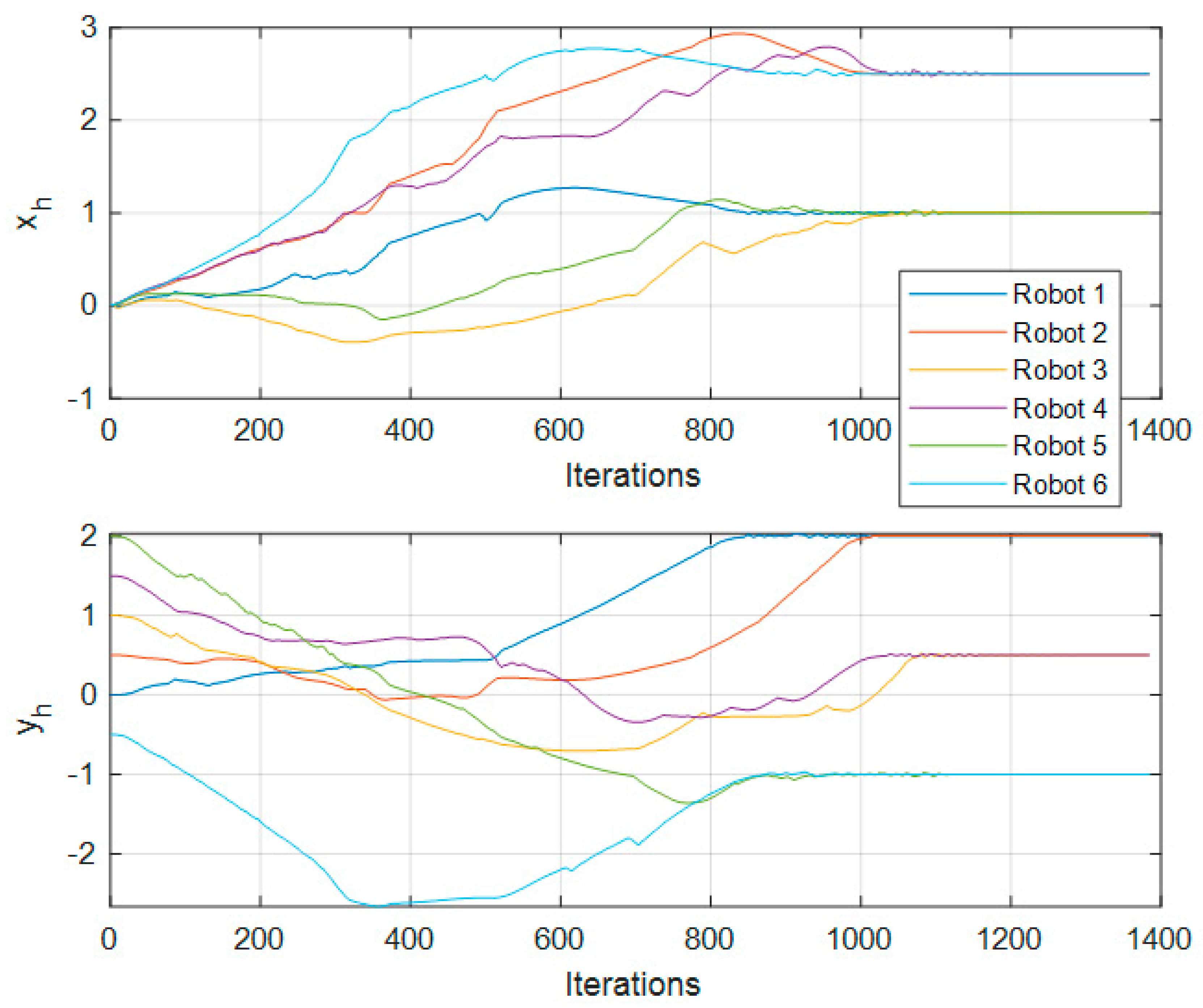
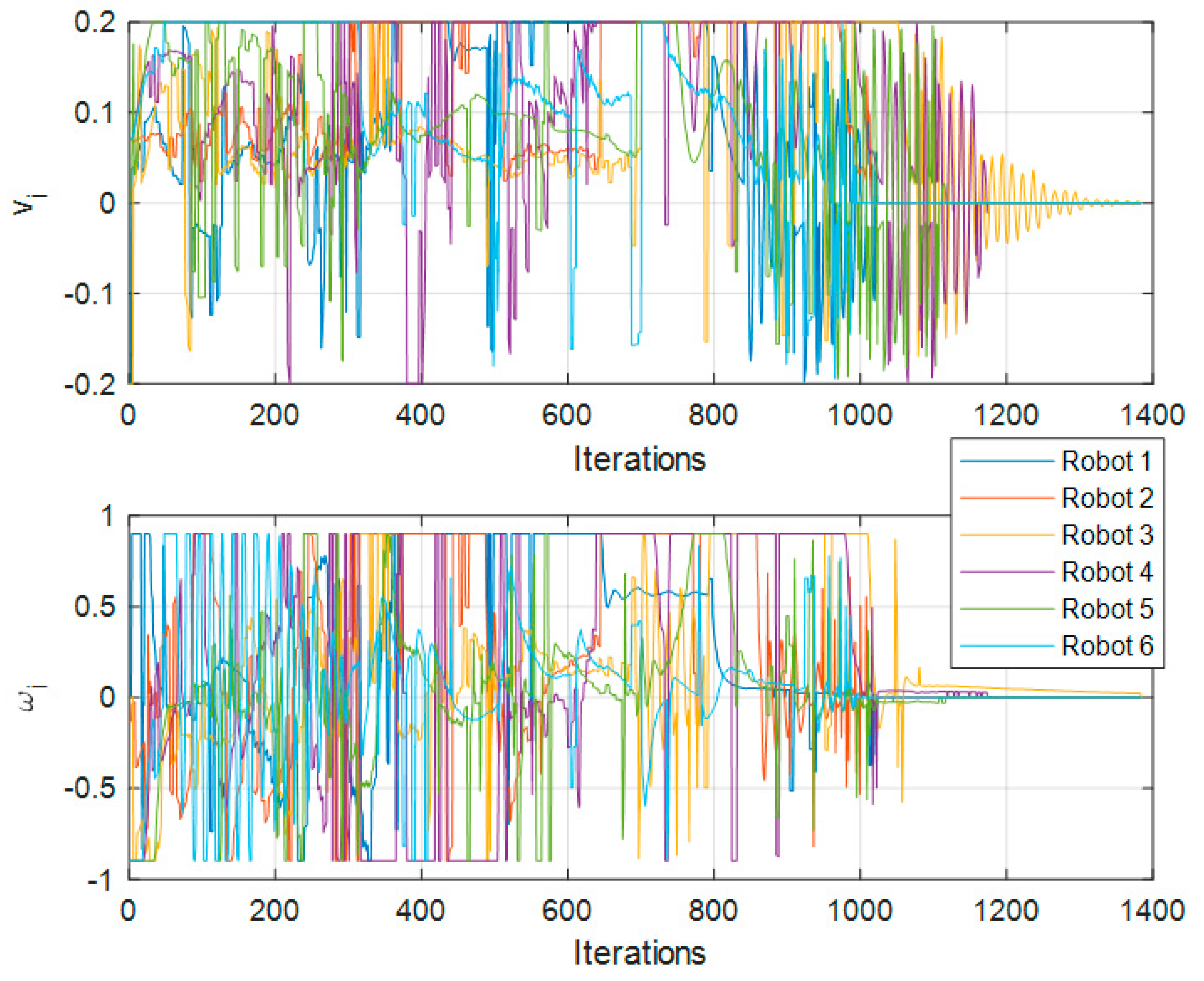
Next, for the 6-robot simulation,
Figure 10 shows the trajectory followed by the robots in the simulation environment.
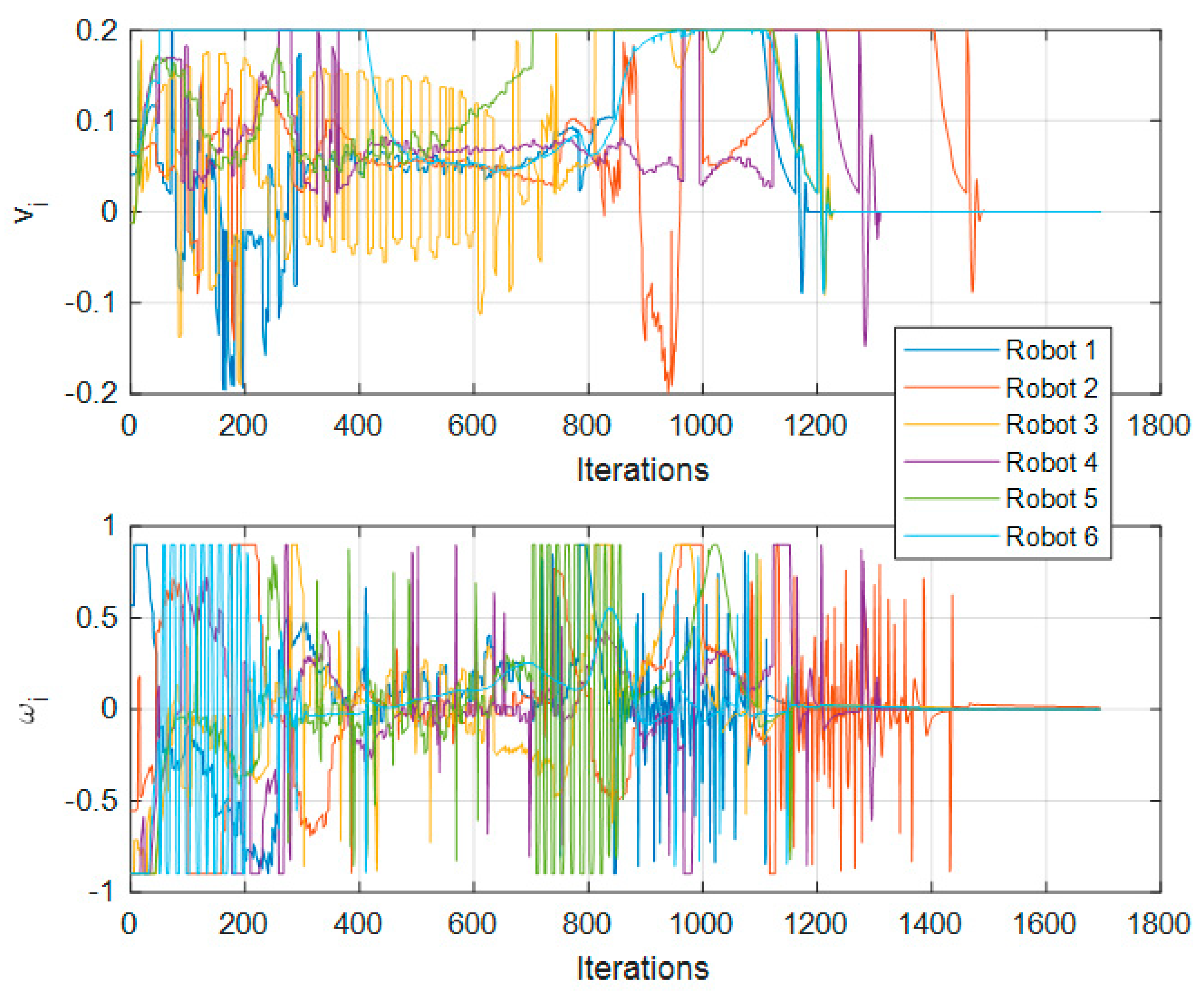
The values of
,
,
, and
for this test are plotted in
Figure 11 and
Figure 12.
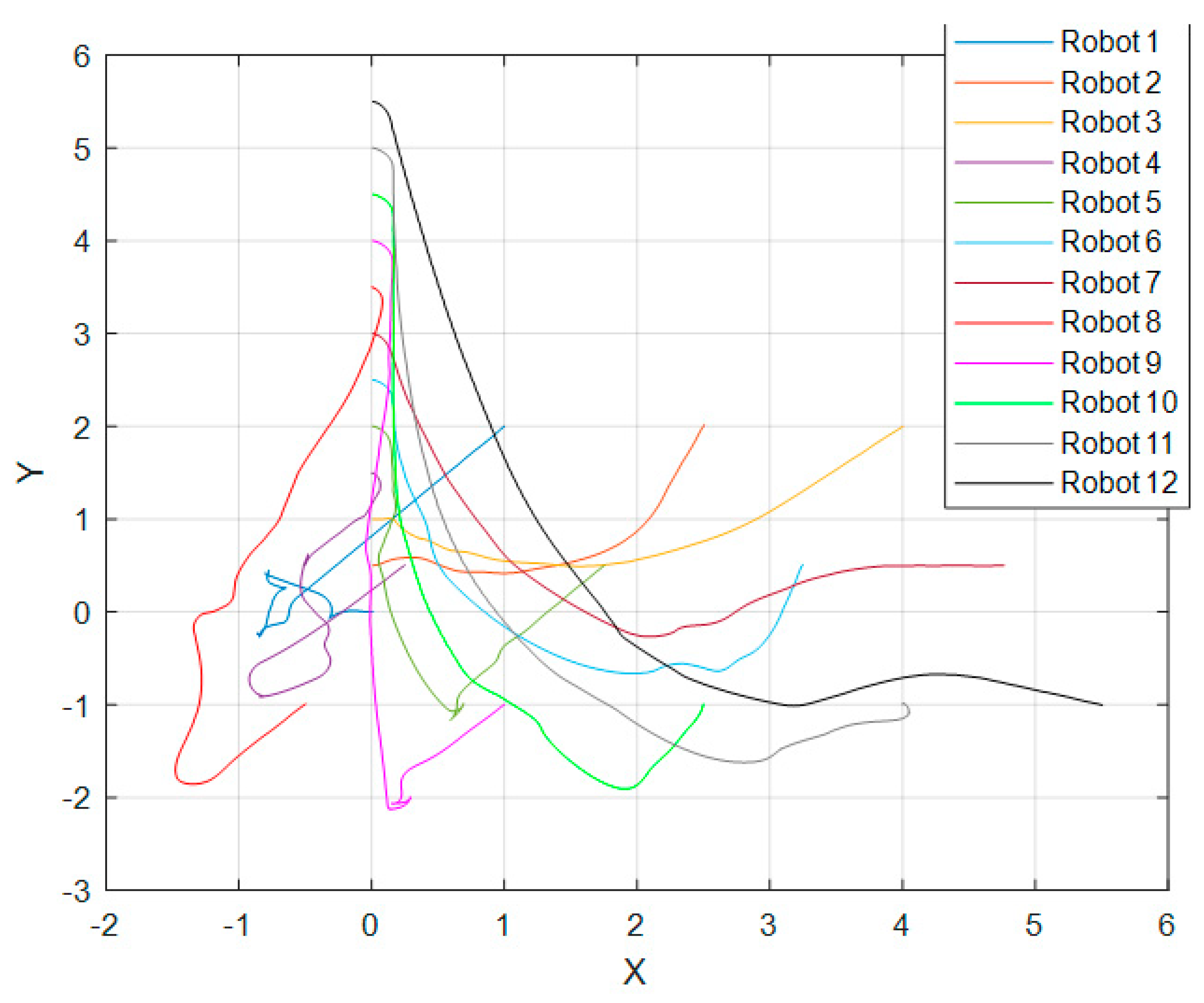
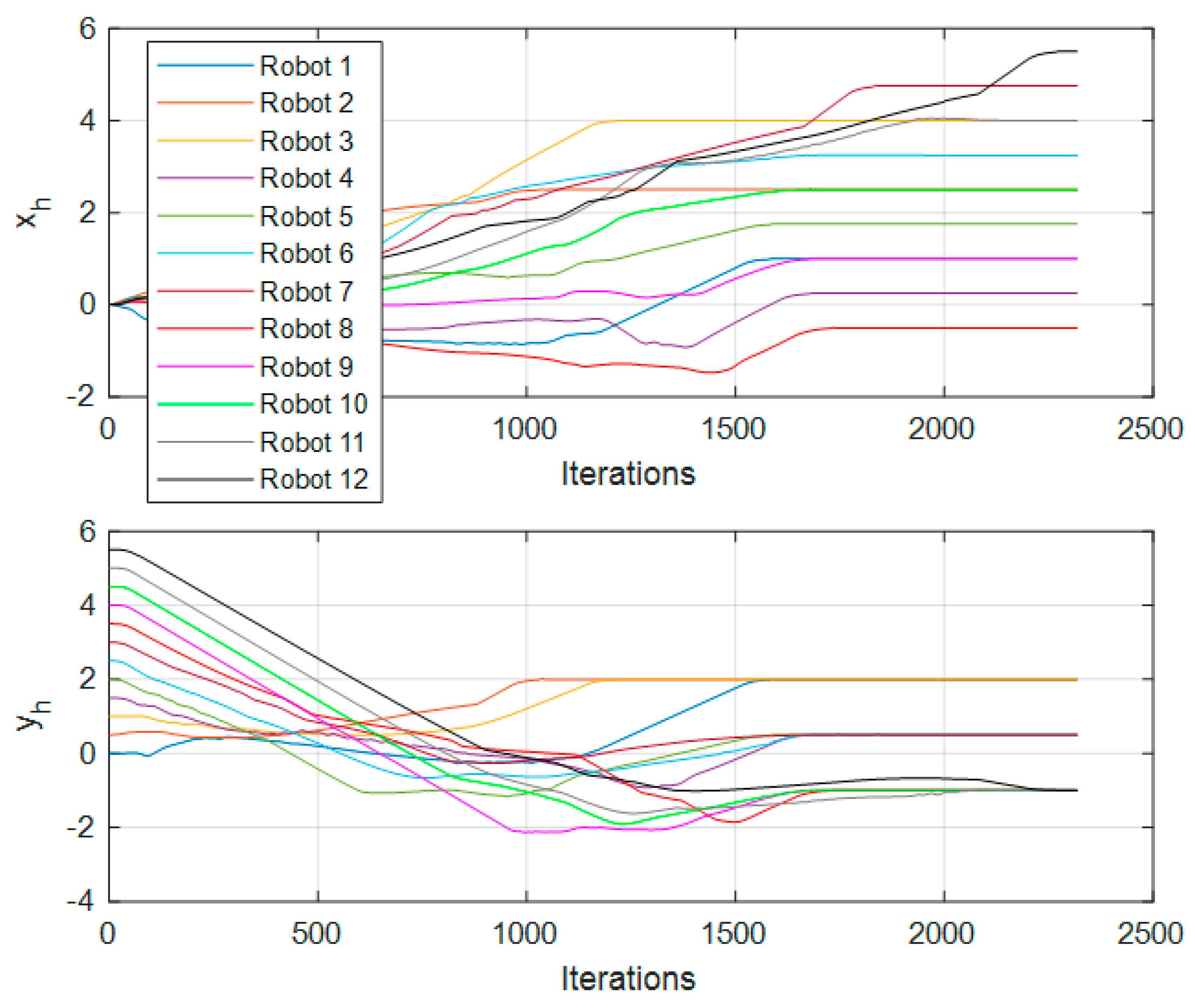
In respect of the 12-robot test,
Figure 13 shows the trajectory followed by the robots in the simulation environment.
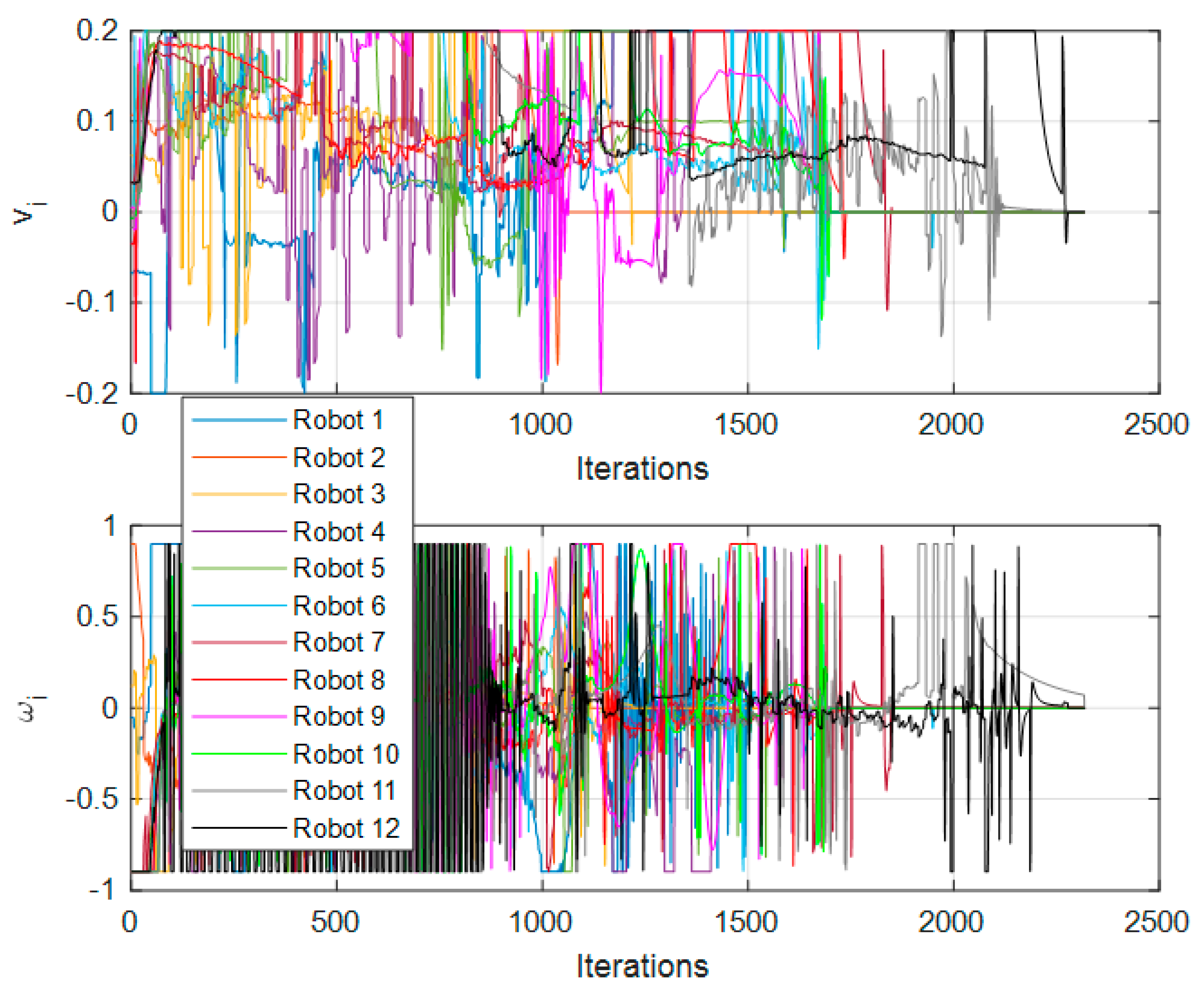
Figure 9,
Figure 12 and
Figure 15 show the control signals
and
of each of the nodes; these figures can be compared against
Figure 8,
Figure 11 and
Figure 14, respectively.
Figure 8,
Figure 11 and
Figure 14 show the nodes changing their position through time (iterations). In
Figure 9,
Figure 12 and
Figure 15, the saturation of signals is noticeable, resulting in a saturation imposed by us to protect the equipment; however, even with this saturation, the proposed approach achieved the desired reference point and formation.
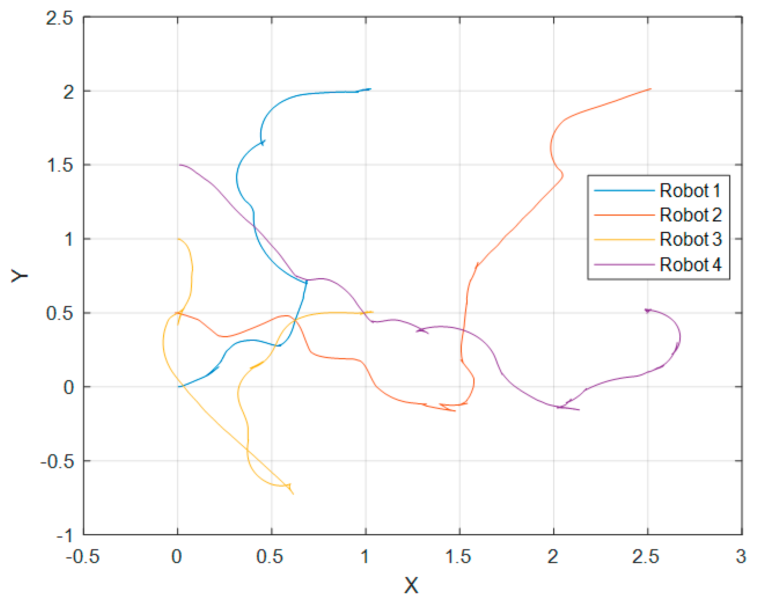
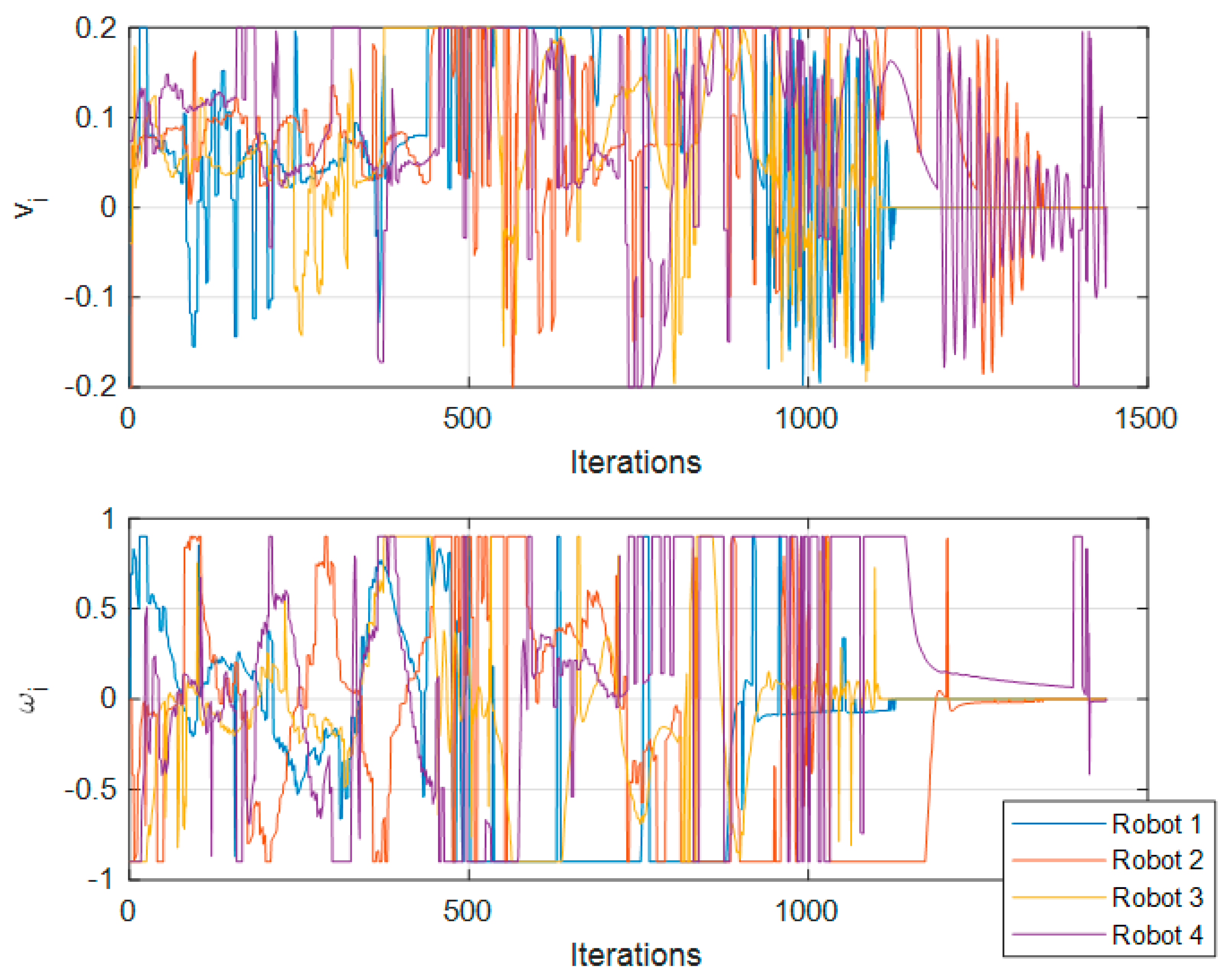
We continued with the experimental tests using the Turtlebot3
® Waffle Pi Robots. First, we present the results for the 4-robot test, where
Figure 16 shows the trajectory of the robots.
The values
,
,
, and
for this test are plotted in
Figure 17 and
Figure 18.
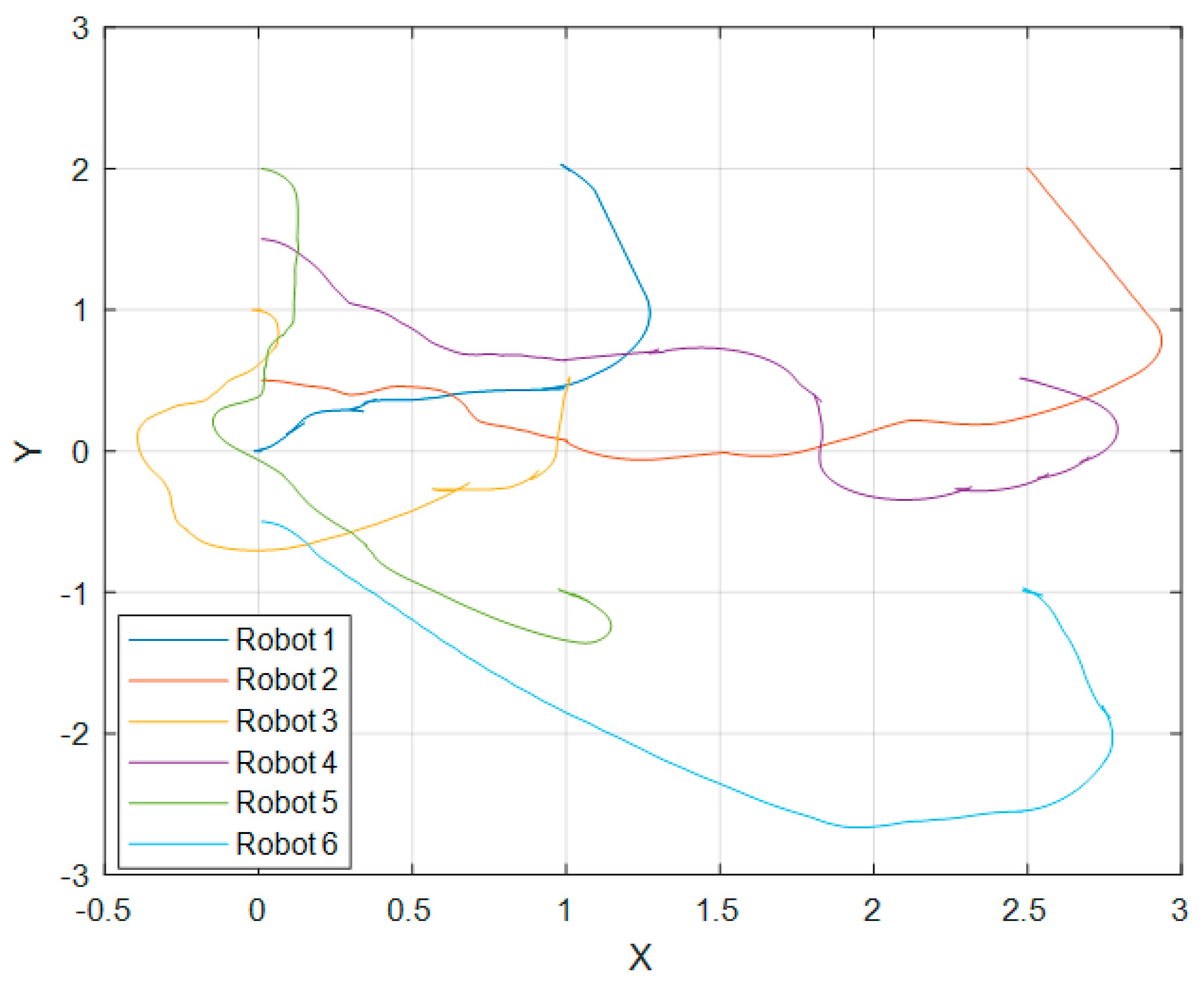
For the 6-robot real experimental test,
Figure 19 shows the trajectory followed by the 6 robots.
Even though pinning control is seen as a decentralized control in the complex network field, the implementation of the proposed scheme is presented as a centralized approach, considering that all computation is left to one computer; however, this can be changed by letting each robot carry out its own control computation, with the only requirement of having each other’s information. More than one robot can be selected for pinning control, and not necessarily all the robots need information from all others, not even from the leader, as seen in the 12-robot simulation.
5. Results Discussion
There are visible differences between the performance of simulation tests under the Gazebo environment and experimental tests with the actual hardware. Many motives explain these differences. Let us begin by discussing the Gazebo platform, a robot simulator environment used in industry and academia. Gazebo computes the robot’s physical and sensory responses in a scenario similar to a real-world one. Even if Gazebo does not consider some real-world factors, it gives results that give us a general idea of the performance of the robots and the algorithms in a real-world application.
Next, the main difference between our simulation and the real-world test results. Gazebo simulations were performed locally; all the ROS packages never left localhost. In the experimental test case, the package passes through a local network via Wi-Fi communications involving loss of packages and delays affecting the performance. Moreover, the scenario where the robots moved is not a perfect flat surface as in the simulation; it has irregularities. Furthermore, the simulation does not consider robot wear conditions and non-model dynamics.
Another important point to discuss is that all nodes in the proposed work are differential-drive robots. However, using complex networks, it would be possible to combine different kinds of robots, including, for example, unmanned aerial vehicles and omnidirectional robots. Let us consider the studies [
10,
11] where non-identical chaotic nodes were used in the same complex network. Judging by their results, we could expect similar results for the proposed control scheme using different robotic platforms. However, the relevant variables to each of the different robots must be first defined.
The results in the previous sections contrast with those presented in other related works, in that the desired formation was achieved on a previously set point on the plane; additionally, using the LiDAR sensor ensures the avoidance of collisions between robots and other nonrobotic elements. Furthermore, other works mainly present results at the simulation level and with fewer robots. For instance, in the study [
17], the authors proposed a formation control scheme that is not achieved on a specific point in space, collisions are only avoided between robots using the previously known positions of each other, and results were presented in simulation for nine robots. The study [
18] is similar to [
17], presenting simulation and experimental results, where a camera obtained the robot positions, and their experimental results used three robots. In [
19], formation control was achieved without a final position reference, using four robots for experimental results, and OptiTrack cameras obtained their position. Work [
20] shows the results of formation control only in simulation, and collision was avoided only between robots. In [
21], a group of robots arrived at a certain point, but the robots appeared to overlap in simulation, which is not physically possible. Work [
22] presents a cooperative control tracking scheme which, compared to our proposal, differs in that all the robots knew the position of each other to avoid collisions in that study, and it presents the use of a virtual point as a reference for the robots. In contrast, our proposal uses one robot as the reference point.
Comparative Analysis
This section presents comparative results between this work proposal and two different formation control schemes. First, we compare the proposed scheme of [
21], where there is no collision avoidance. Second, we compare the proposed scheme of [
17], where there is collision avoidance but no final reference set point.
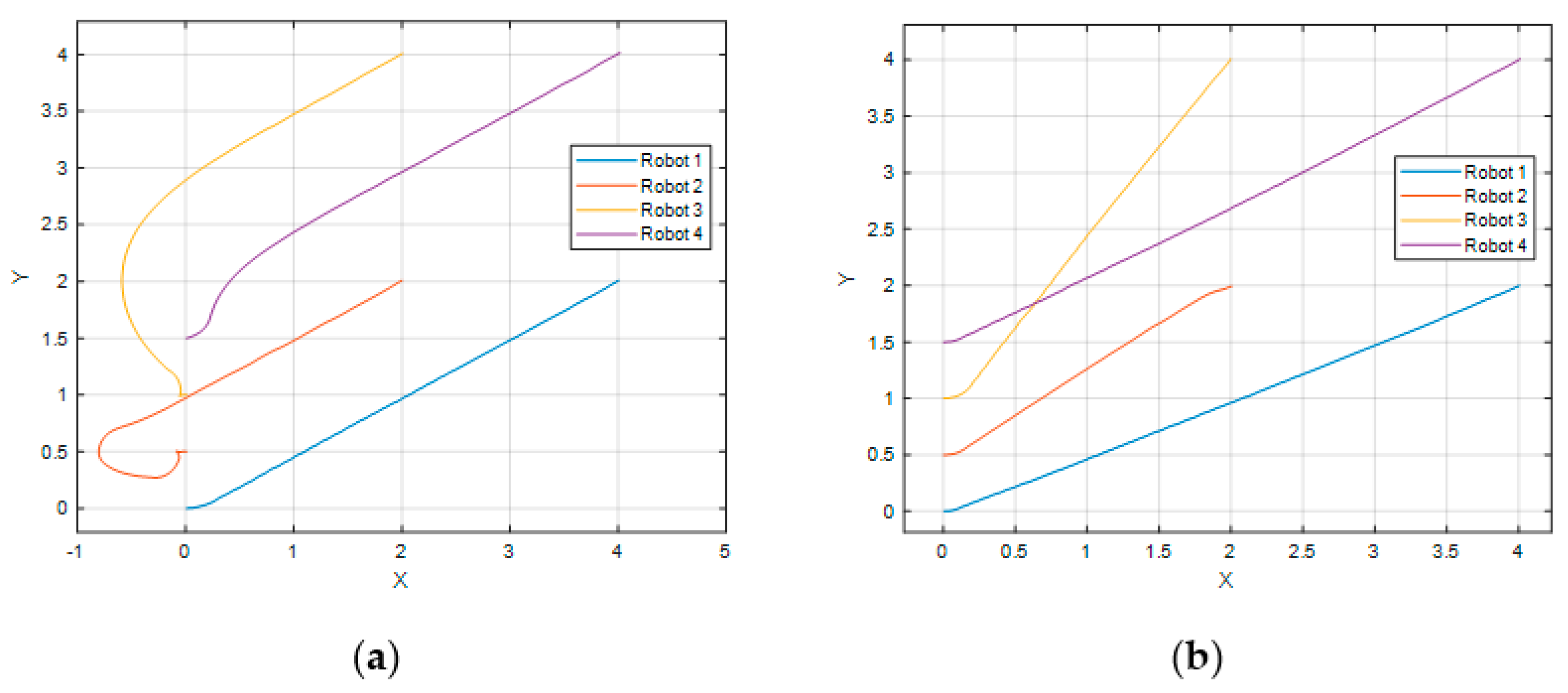
For the first comparison test,
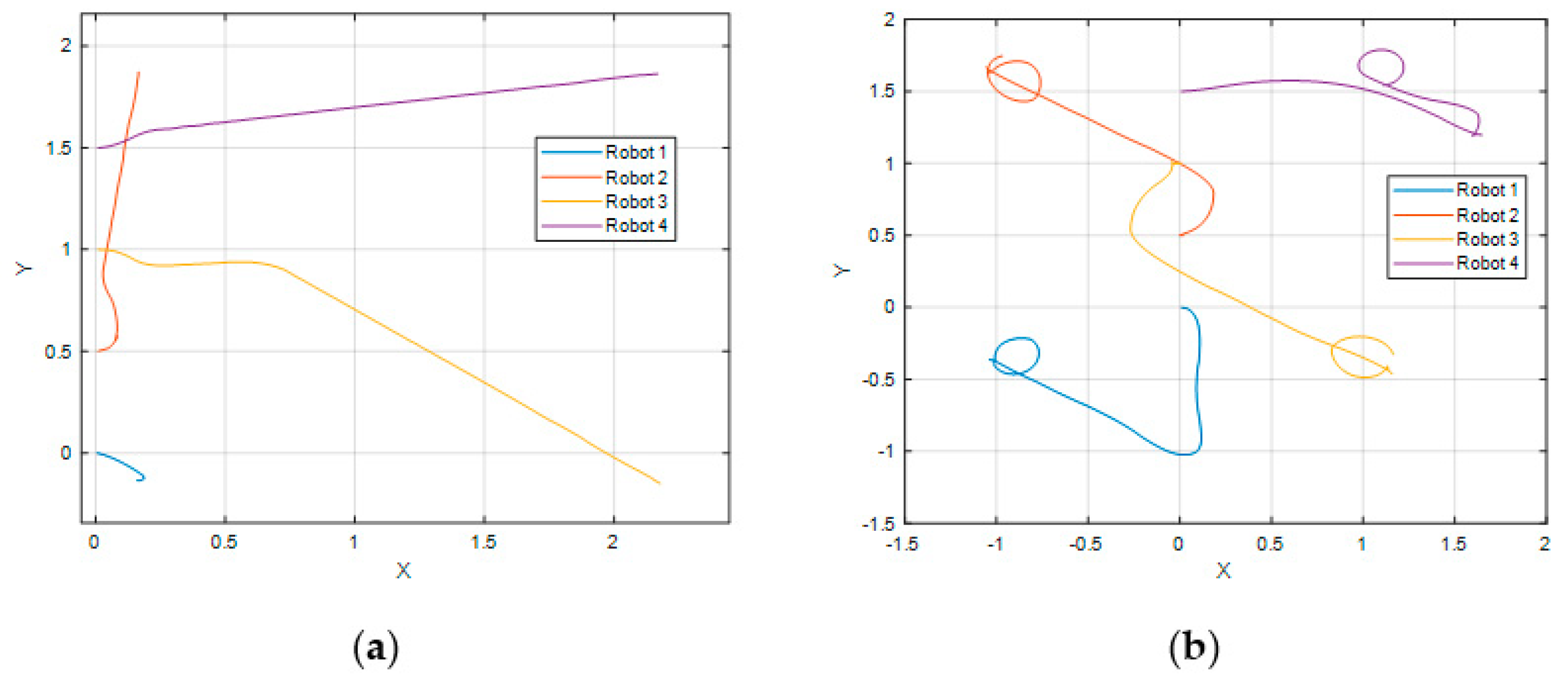
Figure 22 shows a visual comparison of our proposed scheme (
Figure 22a) and the scheme proposed in work [
21] (
Figure 22b). Both schemes reach the goal. It is important to note that in favor of the scheme of work [
21], a final formation and position where collisions would not be a problem was previously selected for this test. However, for most final formations and positions, it would be a task impossible to achieve by the scheme of [
22]. The lack of collision avoidance in a real scenario is not something to be left unattended. Moreover, in work [
22], every robot had a reference controller, which would get more challenging to design if a different, more complex controller is to be implemented in a future application, as it would be necessary to implement one for every robot.
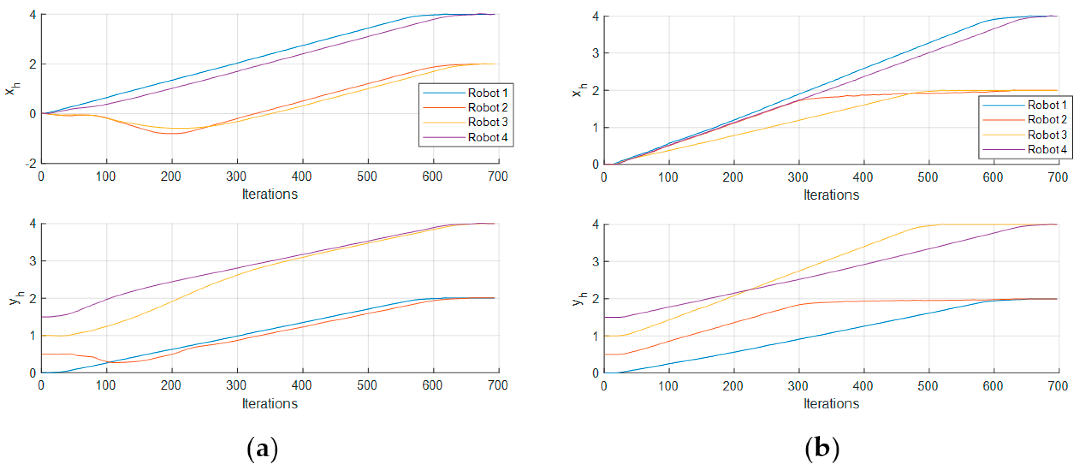
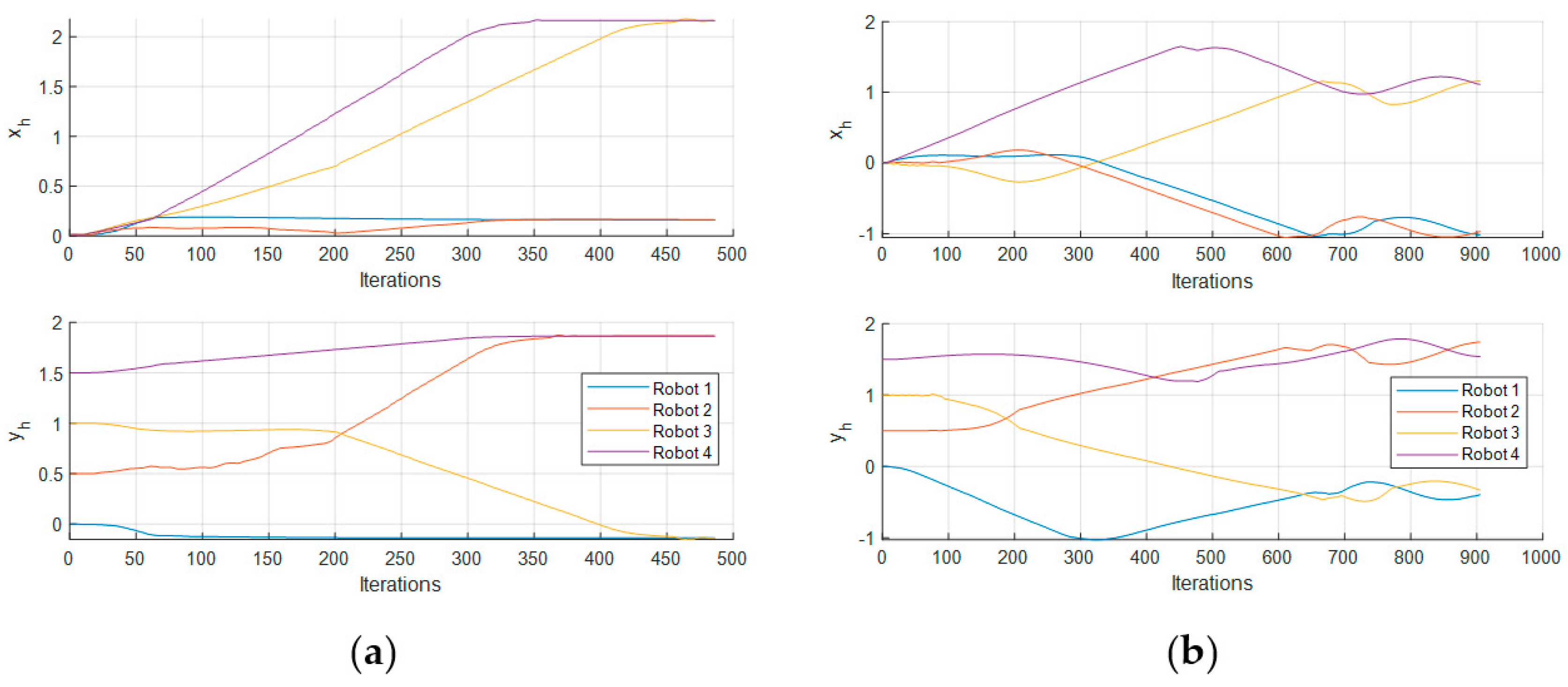
Figure 23 shows the trajectories of both schemes along the iterations, where it can be noted that there is not much difference in the final number of iterations for both schemes, meaning that they achieved the objective almost at the same time.
Now the results of the second tests against the scheme of work [
17] are presented.
Figure 24 shows the movement of the robots in both schemes, this study’s proposal (
Figure 24a) and the scheme of [
17] (
Figure 24b). Since the scheme of [
17] achieves the desired formation in a non-previous specified point, for our scheme, we omitted the final position term for just getting the desired formation.
Both schemes reach the goal; however, there is an oscillation when robots get near to achieving formation in the scheme of [
17]. Collision avoidance in [
17] is performed by following a particular counterclockwise turning movement. In contrast, the proposal presented in this paper follows a more natural path search in every direction as the LiDAR senses all of the surrounding environment, which makes it more practical for real applications.
Figure 25 shows the trajectories where the oscillation at the end can also be observed. It can also be seen that our proposal is slightly faster, judging by the number of iterations, even if we were to finish the test where oscillations begin.
6. Conclusions
The complex network approach allows us to see the pattern formation of the mobile robot’s objective as the couplings of synchronizing a complex network, and such synchronization is achieved using pinning control methodology. In the pinning control method, we only focus on one of the robots to set the desired final position of the formation, where not all the robots are necessarily connected to it, allowing us to combine different numbers of robots. Additionally, as mentioned in
Section 5, combining different kinds of robots would be possible based on previous works focusing on complex networks where non-identical chaotic nodes were used in the same complex network. Some extra work would be necessary, and this idea is left for future studies.
Moreover, using pinning control in combination with complex networks presents an advantage if the position control law is thought to be changed to a more complicated one, since it would only be necessary to worry about modifying the control law for one of the robots.
The results of the presented tests show that the control objective was achieved for different formations, different numbers of robots, and different desired final positions, which is presented in both the simulation and experimental results. Comparative results with other works show that the proposed scheme would be a better option for real applications.
Besides using different robots in the complex network, more future studies can be proposed, including trajectory tracking in formation and dynamic topology of the form complex networks.
