1. Introduction
Cloud manufacturing is a service-oriented manufacturing paradigm in which all of the distributed manufacturing resources involved in the whole life cycle of product production are encapsulated as various manufacturing services [
1]. It then provides on-demand manufacturing services for personalized manufacturing tasks submitted by consumers, so as to finally improve the response speed to meet the personalized requirements for customers and the utilization rate of manufacturing resources for manufacturers. At present, most researchers focus on these scientific issues, including virtualization and servitization encapsulation of manufacturing resources, manufacturing service selection, matching and combination. The successful implementation of service matching and composition needs to determine the current production capacity of manufacturing resources according to their real-time running status and load conditions, and then select and optimize the service combination based on this. However, the working state and workload of manufacturing resources can only be obtained by analyzing and processing the corresponding field operational data of manufacturing equipment. The operational and status data of manufacturing resources provide basic informational support for the industrial applications of the cloud platform (such as matching, selection and combination of manufacturing services, equipment fault diagnosis), and are used to drive the stable operation of business. That is to say, the efficient acquisition, transmission and integration of the working state data and related sensor data of distributed manufacturing resources have become the key research issue in cloud manufacturing. However, there is little research on how to upload and transmit the operational data and production status of distributed manufacturing resources to the cloud platform.
Up to now, the existing literature studies have fulfilled the cloud-based access operation of physical equipment data through supervisory control and data acquisition (SCADA), open platform communications unified architecture (OPC UA), ISA-95, etc. All the above methods are used to store, transmit and query the equipment data from the physical workshop to the cloud in a centralized process. It is not only difficult to guarantee the real-time data query requirements of cloud applications (i.e., order completion time prediction [
2] and equipment fault diagnosis [
3]), but also to avoid the serious overload of the cloud platform computing workload. This will lead to the slow response speeds of cloud applications in order to deal with unpredictable events, such as poor performance of task scheduling and difficulty in quickly rescheduling manufacturing resources when the pre-established service composition is abnormal. Therefore, the efficient and low-delay network transmission of field equipment data is the basic and key technology of all networked and service-oriented manufacturing systems.
With the continuous development of edge computing theory, the edge gateway [
4] has become a new tool to establish information communication and data transmission between physical manufacturing resources and the cloud platform. It undertakes a part of the computing workload of the cloud platform to ensure the real-time performance of data analysis applications. The edge gateway is a development platform that integrates the core capabilities of network, computing, storage, and application at the edge of the network close to the data source, and provides edge intelligence services to meet the key requirements of digital factories in agile connections, real-time business intelligence, data analysis, and intelligent decision making. With the help of the edge gateway, it is not necessary to upload all of the generated data of the workshop to the cloud directly. The edge gateway preprocesses the operational data and sensor data of physical manufacturing resources, and analyzes the local data to a certain extent. Then, the preprocessed data and key data are uploaded to the cloud, and the cloud platform mainly focuses on big data processing and the execution of industrial applications with large amounts of computation. To sum up, cloud–edge collaboration not only greatly improves the real-time response speed of cloud applications, but also reduces the computing load of the cloud platform, which shows great potential for the development and application of the cloud manufacturing system.
The structure of the paper is organized as follows: Firstly, the background for, and key issues of, cloud manufacturing and cloud–edge collaboration is presented in the “Introduction”. An overview of the relevant literature in terms of the service-oriented manufacturing paradigm and the Industrial Internet of Things is discussed in the “Literature Review”. The section entitled “Research Methodology” elaborates the framework of the cloud manufacturing system, service-oriented informatization model, data transmission and integration method and the cloud–edge collaboration mechanism for training the artificial intelligence (AI) model. A prototype cloud manufacturing system with the functions of distributed manufacturing resources for cloud access and AI model training is designed, and two types of experiments are applied to verify the effectiveness and superiority of the above-proposed method in the “Case study”. Finally, the “Conclusions” section summarizes the key technologies and achievements demonstrated in this paper.
3. Research Methodology
3.1. The Overall Framework of the Cloud Manufacturing System Based on Edge Intelligence
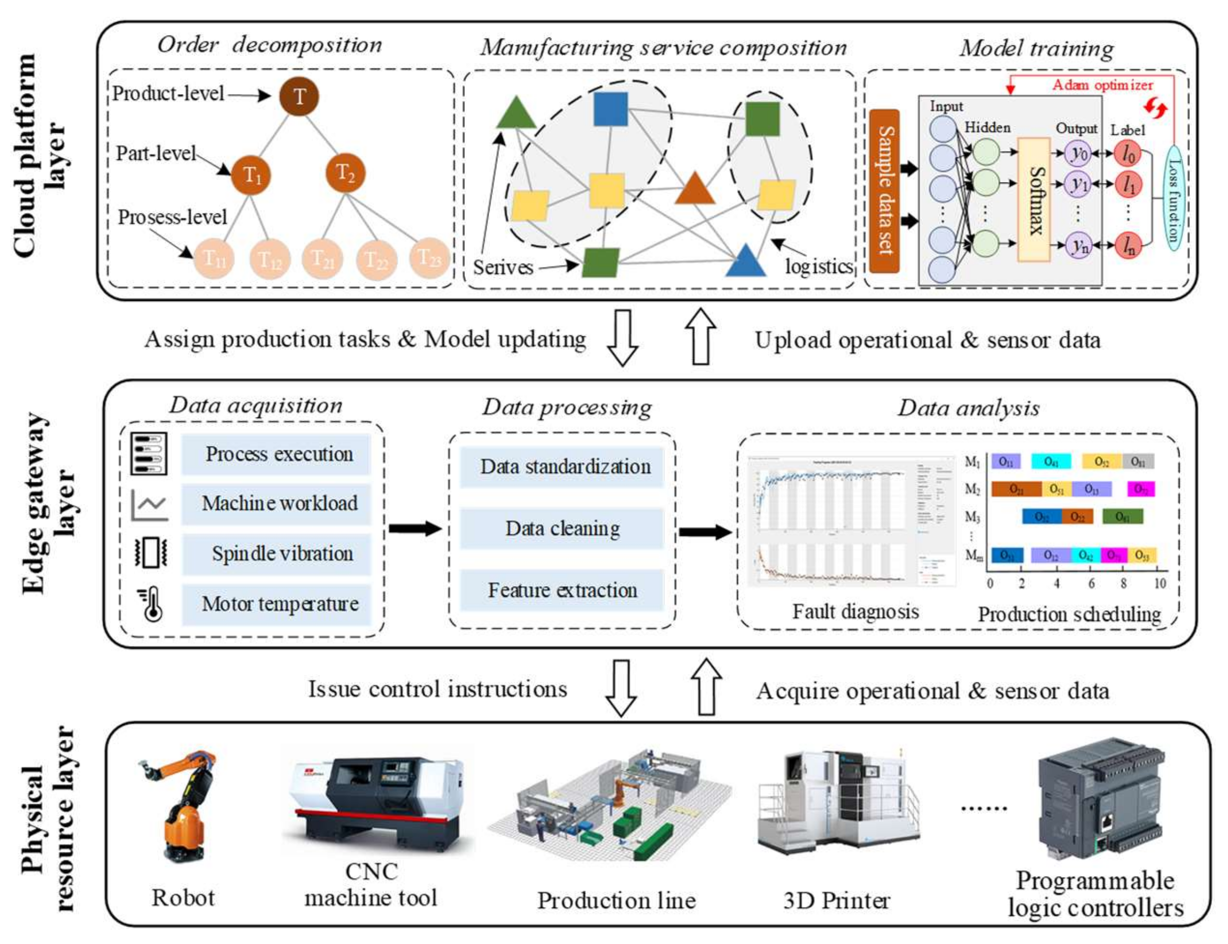
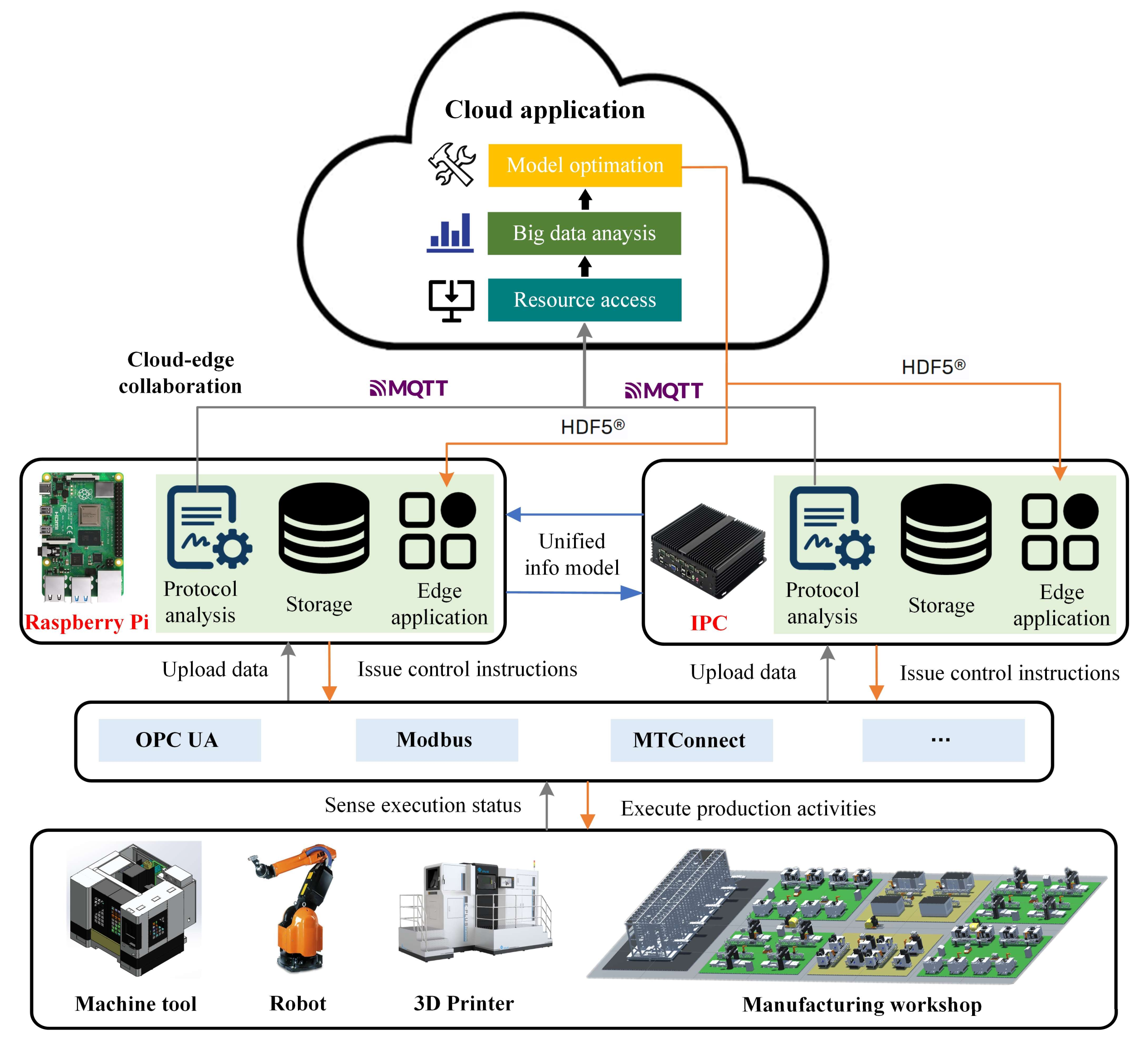
Inspired by the edge computing theory, a three-layer IoT framework (including physical resources, edge computing node, and the cloud platform) is developed to meet the requirements of real-time local data analysis and application, as well as the efficient training of AI models and big data analysis. The physical resources are the executors of production activities and the sources of mass manufacturing data. The edge computing node is responsible for real-time processing, analysis, and application of the collected local data. The cloud platform is responsible for analyzing the stored mass manufacturing data, driving the stable operation of industrial applications and the efficient training of the AI model.
The overall framework of the cloud manufacturing system consists of three parts: the cloud manufacturing platform layer, edge gateway layer, and physical resource layer. The cloud manufacturing platform is equipped with powerful computing, data storage, data processing, and data analysis capabilities. Industrial applications with various functional types are deployed and ran in the cloud platform, including task decomposition, service matching, selection and composition, model training and remote monitoring of workshop execution processes. Among them, service matching and composition are the key components, which organize and configure manufacturing services efficiently to meet changing product requirements. In addition, with the support of strong computing power, machine learning models, including the equipment fault diagnosis model, remaining life prediction model, order completion time prediction model, etc., could be trained and optimized periodically by the cloud platform so that the optimized machine learning model can be downloaded and deployed in the edge gateway. The concept of “Edge” refers to the physical workshop, which is composed of a great deal of manufacturing equipment, and has the ability to provide the part-level production services.
The edge gateway is a bridge for information communication and business cooperation between the physical manufacturing resources and the cloud platform. It is connected to the manufacturing resources through Ethernet, serial port, and radio frequency identification (RFID), and is connected to the cloud platform based on MQTT protocol. The edge gateway can not only capture equipment operational data and sensor data, but also send control instructions to equipment or workshop systems based on the data analysis results of its edge application. The physical resource layer refers to all manufacturing entities involved in the whole life cycle of product manufacturing, and is the core executor of production activities, which mainly include CNC machine tools, machining centers, 3D printers, robots, and logistics equipment, etc. In addition, programmable logic controllers (PLCs), as the most popular type of controller in the real-world industry, should also be placed in the physical resource layer.
The running logic of the cloud manufacturing system is shown in
Figure 1. Firstly, heterogeneous physical manufacturing resources are encapsulated into various manufacturing services according to their functions, characteristics, and performance parameters, and are shared and configured in the cloud platform. Secondly, the connection between the cloud platform and physical workshop is established through the edge gateway. The edge gateway captures the real-time data of equipment workload, spindle vibration, motor temperature, operational process, and workpiece processing progress from the physical equipment. The collected data are subsequently preprocessed, including data standardization, data cleaning and feature extraction. The preprocessed data are input into various edge applications for data analysis, such as equipment fault diagnosis and remaining life prediction based on spindle vibration information, and production scheduling based on the workload of equipment and process attributes of work in progress (WIP). Based on the data analysis results, control instructions will be released to physical manufacturing resources to guide them to complete the corresponding production actions.
In addition, the equipment-related, sensor-related, and product-related operational process data will be uploaded to the cloud platform after preprocessing, and stored in the cloud database. These data are distributed to various industrial application interfaces of the cloud platform in a publish–subscribe system. On the one hand, the collected industrial big data are analyzed and processed by the cloud platform, and are streamed to the industrial application data items they intend to stream to the cloud (i.e., remote monitoring, task scheduling, manufacturing service matching and composition). For example, the orders submitted by consumers are decomposed into the part-level manufacturing tasks, and then various manufacturing services are matched and combined based on the working status and performance indicators of shared manufacturing resources in the resource pool of the cloud platform to form a service scheduling scheme. Finally, part-level manufacturing tasks are distributed to the edge server of the corresponding workshop based on the scheduling scheme. On the other hand, the cloud intelligence application will periodically read and query the historical data of the execution process of the equipment/workshop stored in the database, which will be applied to train and optimize the parameters of the machine learning models deployed on the edge gateway (i.e., the equipment fault diagnosis model, the remaining completion time prediction model, and the production scheduling model). Finally, the updated machine learning model is deployed and downloaded to the edge gateway in a cloud–edge collaborative process. It is beneficial to enhance and upgrade the analysis ability of edge applications. Finally, the physical manufacturing resources carry out production activities according to the control instructions issued by the corresponding edge gateway.
3.2. Service-Oriented Informatization Model for Manufacturing Equipment
In the cloud platform, manufacturing resources (i.e., CNC machine tools, 3D printers, and robots) from different regions and different enterprises are encapsulated into various types of manufacturing services, aiming at providing service demanders with on-demand service compositions. How to describe heterogeneous manufacturing services has become a research issue. In this paper, a service-oriented manufacturing resource informatization model is established to describe manufacturing resources with different structures and functions in a unified way, and provide informational support for subsequent service matching, composition, and scheduling, and other applications.
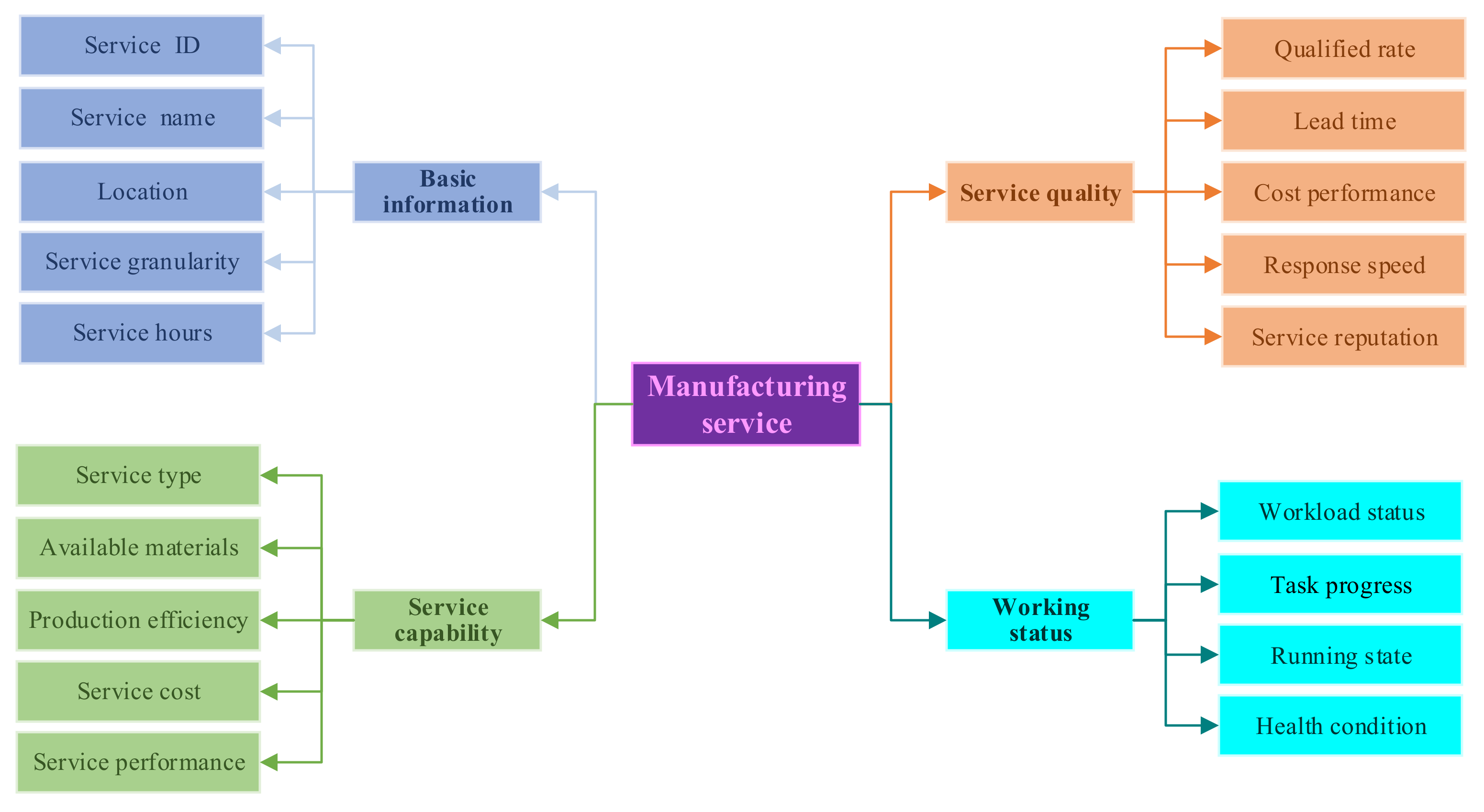
As shown in
Figure 2, the information model of manufacturing services consists of the following parts: basic information, service capability, service quality, and working status. The basic information shows the ID, name, geographical location, granularity, and working hours of manufacturing services. Service granularity is divided into three levels, the process-level, part-level, and product-level, which correspond to the granularity of manufacturing tasks when performing service matching operations. Geographical location refers to the geographical location of the manufacturing services, which is used to determine the logistics costs of products transferred between manufacturing resources when performing service composition operations. Working hours refers to the daily working hours of the manufacturing service, and the unit of its value is min/d. Service capabilities mainly describes the static function and dynamic performance of manufacturing resources, including service type, available material information, production efficiency, service cost per unit time, and service performance. Service types include machining, 3D printing, etc. The available material information indicates the materials that can be processed by the manufacturing service. Production efficiency refers to the speed at which manufacturing services complete each task, and the range of its values provided by service providers according to the experience of operators. In the case of machining service, the service performance indicates the machining size of the part, the machining accuracy of the process and the achievable surface roughness. In the case of 3D printing service, the service performance indicates the printing size, printing accuracy, and printing shape. Service quality is determined by the following aspects: product qualification rate, delivery cycle, cost performance, response speed, and service reputation. The qualification rate indicates the comprehensive qualification rate of the manufacturing service to complete all manufacturing tasks to date. The response speed indicates the time from receiving the task request sent by the platform to confirming the receipt of the manufacturing task. Service reputation reflects the evaluation of service demanders to service providers after the completion of manufacturing tasks, and is periodically maintained and updated by the platform manger. Service performance and service quality are used as indicators to guide the matching of manufacturing services with manufacturing tasks. Working status shows the current workload status, task progress, running state, and health condition of manufacturing services. Among them, workload status consists of idle, light load, and full load. Running state indicates the operation status of key components or the whole instrument, including surface temperature, vibration, working current, spindle speed, etc.
3.3. Data Transmission and Integration Method Based on Message Middleware
The operational data and sensor data of field-level manufacturing equipment are the bases supporting the stable operation of various industrial applications in the cloud platform. Therefore, how to acquire, transmit, and store the real-time data of massive and heterogeneous manufacturing equipment from different regions and different enterprises have become some of the key technological factors for the successful implementation of the cloud manufacturing system. Various types of manufacturing equipment are connected with edge gateways (i.e., Raspberry Pi and industrial personal computers) through Ethernet ports. The acquisition of operational data and the release of control instructions are realized with the support of the connection between the edge gateway and manufacturing equipment. The overall data transmission and integration process is shown in
Figure 3.
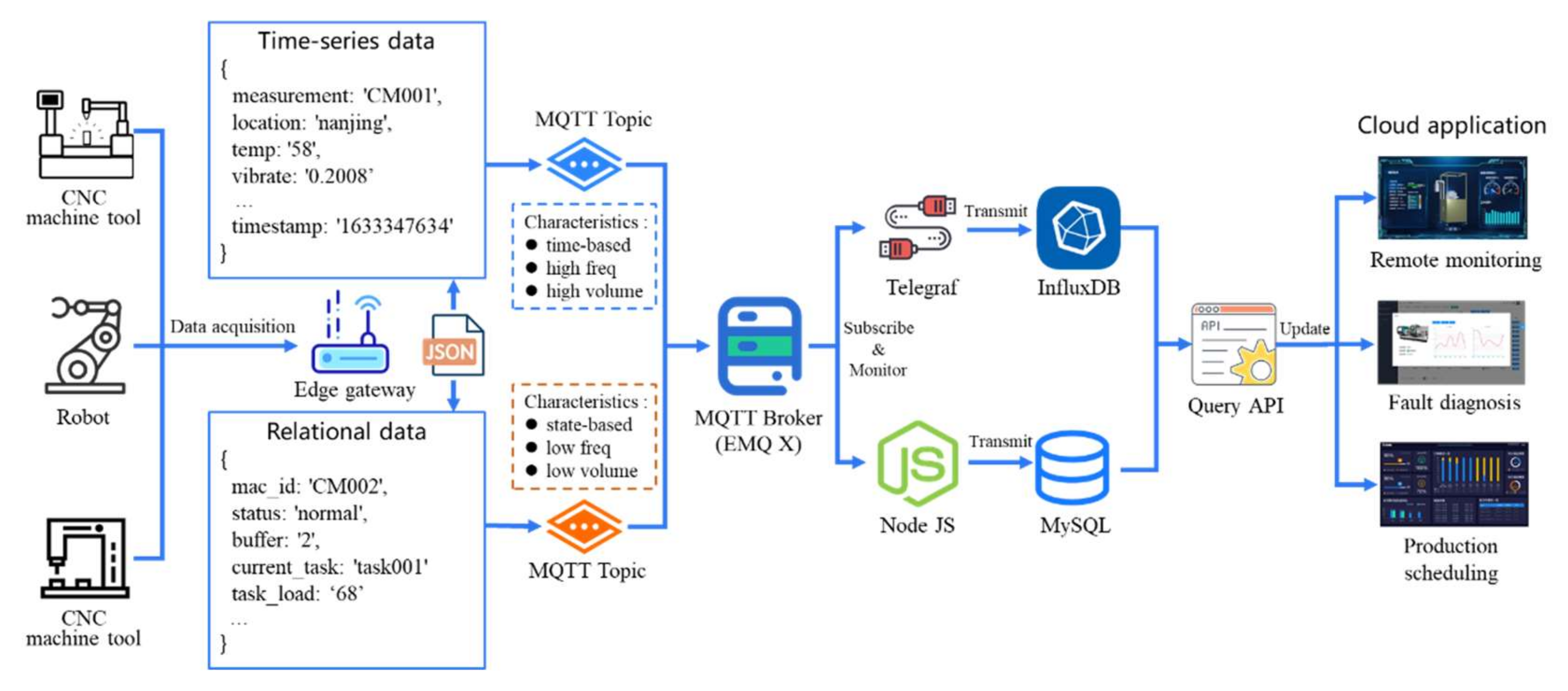
Firstly, the intelligent gateway deployed at the edge of the workshop is applied to acquire the operational data and sensor data of manufacturing equipment with different communication interfaces and industrial protocols (i.e., Modbus, Modbus TCP, OPC UA, and Focas) through its protocol analysis module. The acquired data mainly include the operational data related to manufacturing equipment (i.e., machining progress, working status, and remaining workload), the relevant sensor data (i.e., spindle vibration, motor temperature, and working current), and the execution process data of the workshop. The operational data of manufacturing equipment include spindle speed, operation status of machine, remaining tasks to be processed in the buffer, operation information of current jobs, machining progress of production tasks, total number of processed workpieces, working status, and alarm information. The execution process data of the workshop include job scheduling scheme, product qualification rate, machine utilization rate, and workload distribution of various machines. The sensor data mainly include the vibration signal and acoustic emission signal of the spindle motor, the working current of the equipment, and the surface temperature of its key components.
According to the characteristics of the data, the collected equipment data are divided into time series data and relational data. The time series data mainly refer to the sensor data collected from the equipment, and exhibit the characteristics of time dependence, high frequency, and high volume. The time series data are conducive to the deep learning model to evaluate the state and performance of manufacturing equipment. For example, the fault diagnosis model analyzes the fault cause of the machine tool based on the vibration data of the spindle motor. The relational data mainly refer to the working status of manufacturing equipment or workshop system, and possess the characteristics of state dependence, low frequency, and low volume. The relational data are used to assist the service matching and composition module application in the cloud platform to make the task allocation decisions and manufacturing resource configurations, and are also applied to support the model training application in the cloud platform to optimize the scheduling strategy of workshop production activities.
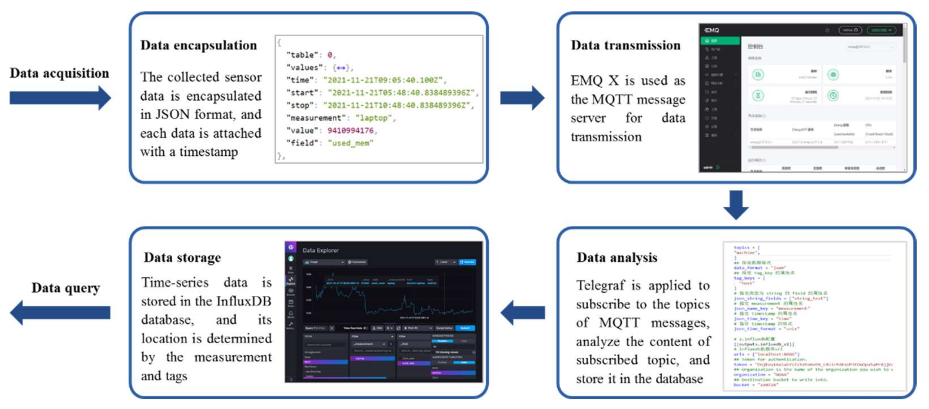
Secondly, both of the above two types of equipment data are encapsulated in a JavaScript Object Notation (JSON) format. The JSON format has the characteristics of simple structure, easy reading and writing capacity, low bandwidth occupation, and is compatible with various programming languages (i.e., Python, Java, and JavaScript). The JSON file format of time series data is shown in
Table 1, which consists of various necessary attributes such as measurement, tag, field, and timestamp. The measurement indicates the identification of the shared equipment. The tag data indicate the basic information of the shared equipment with index (i.e., ownership, location), and are stored in the form of key–value pairs. The field data indicate the real-time sensor data without indices (i.e., temperature, voltage, vibration, and spindle speed), and are stored in the form of key–value pairs. The timestamp indicates the time point of data collection. Among them, the attribute names of measurement, timestamp, and tag need to be specified in a data collector called Telegraf. However, it is not necessary to specify the attribute names of the field data. The JSON file of relational data contain attributes such as equipment identification, device working status, and task execution progress. The transmission and storage procedures of the time series data are shown in the
Figure 4.
The JSON-format data are then published via MQTT Broker (i.e., EMQ X) in the form of MQTT topics through MQTT client on the edge gateway. MQTT Broker is a message server oriented to MQTT protocol, which acts as a message middleware system, and is applied to transmit and distribute the collected data related to physical equipment instantly. Telegraf is a data collection tool for InfluxDB, developed by InfluxData Company. It is applied to monitor and subscribe the topics of MQTT messages, analyze the content of subscribed topics, and store these data corresponding to the topics in the time series database InfluxDB. The storage location of the data is determined by the measurement and tags in the JSON data schema. The topics of the relational data are subscribed to the message middleware through NodeJS service, and the corresponding data are stored in the relational database MySQL.
Finally, industrial applications (i.e., equipment status monitoring, predictive maintenance, service composition, and equipment fault diagnosis) exchange information with InfluxDB and MySQL databases through the predesigned query interfaces to obtain real-time running data of distributed equipment, thus establishing a technical foundation for driving the equipment remote monitoring module, real-time detection of processing progress, and fault diagnosis of high-end equipment.
3.4. Cloud–Edge Collaboration Mechanism
Edge intelligence is a new technical scheme combining edge computing with artificial intelligence. On the one hand, with the development of the Internet of Things, the generated data from physical manufacturing equipment need to be analyzed by intelligent algorithms to realize intelligent data application and provide higher data usability. The intelligent algorithms represented by deep learning can extract implicit and effective information from equipment data to improve the efficiency and accuracy of decision making. On the other hand, edge computing can provide more real-time data and application scenarios for intelligent algorithms. Generally speaking, artificial intelligence (AI) and big data analysis applications are deployed and ran in cloud servers and big data centers, while edge computing nodes can directly obtain massive operational data from physical equipment and realize intelligent calculation and analysis, which will strongly promote the further popularization and development of AI applications, especially IIoT-enabled applications. The proposed cloud–edge collaboration mechanism is shown in
Figure 5.
In the workshop, the edge gateway establishes communication connection with manufacturing equipment, robots, and logistics equipment. The functional modules of gateway are composed of protocol analysis, data storage, and edge application. The industrial protocols carried out by different equipment are inconsistent (i.e., OPC UA, OPC DA, Modbus, Modbus RTU, and MT Connect). The edge gateway carries out information extraction, data format conversion, and data preprocessing on real-time and heterogeneous equipment data collected from the bottom layer through the protocol analysis module. The preprocessed industrial process data are then stored in the edge server in a standardized format, and the data access interface is provided to the edge application. The edge gateway is responsible for the localized analysis and processing of real-time equipment data and workshop operational data, which improves the security of industrial process data analysis and real-time data processing. For example, the equipment fault diagnosis application deployed on the edge gateway can analyze and judge the fault causes of machine tools through the collected spindle vibration data and motor surface temperature. In addition, the production scheduling application schedules tasks and resources according to the working state of equipment, and the process attribute information of WIP. Based on the analysis results of edge applications, the edge gateway sends task requirements and control instructions to the corresponding equipment to guide them to complete the production activities. Information communication between gateways is based on a unified information model, which can realize task division, cooperation, and information sharing.
In addition, the artificial intelligence model of edge application is constantly being updated and optimized with the help of the cloud–edge collaboration mechanism. The resource access module in the cloud platform subscribes to related topics of messages through MQTT protocol, and receives the preprocessed industrial process data from the edge. These data will be stored and managed in the cloud database for other industrial applications to call. For example, the big data analysis module calls historical data about equipment operation or workshop operation, and extracts useful characteristic information behind the data. With the powerful computing performance of the cloud platform, the model optimization module trains and optimizes the artificial intelligence models (i.e., equipment fault diagnosis model, production scheduling model, logistics scheduling model) by feeding into the platform labeled historical sample data, the extracted feature information, and various optimizers (i.e., Adam, RMSProp, and SGD). Then, the neural network parameters of the trained artificial intelligence models are generated into Hierarchical Data Format Version 5 (HDF5) files. These HDF5 files are then transmitted, deployed, and updated at the edge gateway through TCP/IP protocols, which are applied to upgrade the parameters of machine learning models in edge applications.
The efficient training and flexible deployment mechanism of the artificial intelligence model based on cloud–edge collaboration will provide a large number of modular, plug-and-play, intelligent data analysis tools, and edge applications for manufacturers in the discrete manufacturing field, and continuously improve the intelligent manufacturing capacity of factories. At the same time, it takes advantage of the real-time performance of edge intelligence and the powerful computing and analysis capabilities of the cloud platform.
4. Case Study
4.1. Cloud Access and Remote Monitoring of Distributed Manufacturing Resources
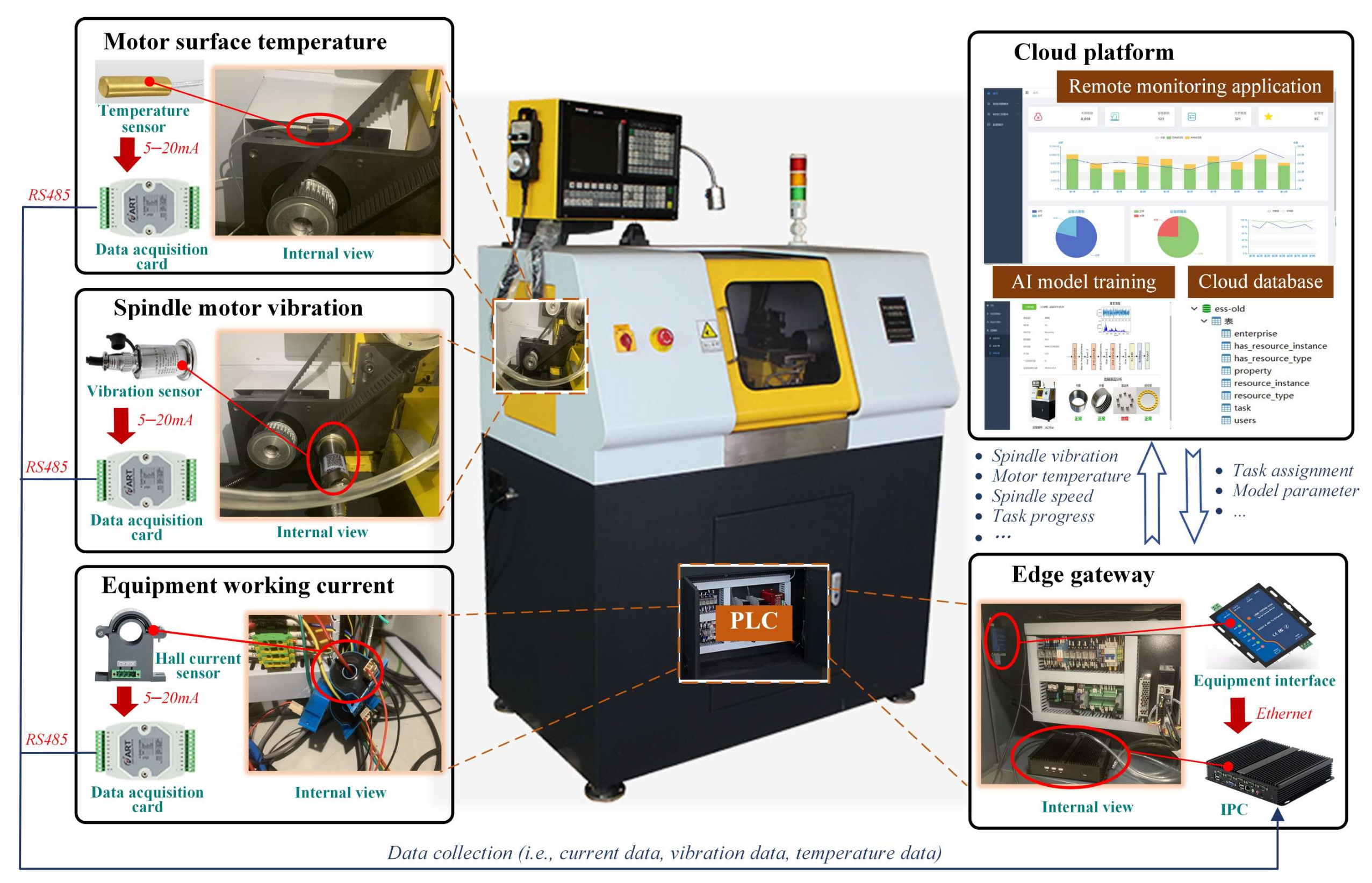
In this paper, the computer numerical control (CNC) lathe is selected as the experimental object to verify the effectiveness of the cloud access and remote monitoring methods proposed in this paper. As shown in
Figure 6, the temperature sensor, vibration sensor, and hall current sensor are installed to sense the surface temperature, motor vibration, and working current of the spindle motor of the CNC lathe. The data acquisition card is used to collect the output analog signals (i.e., 5–20 mA) of the sensors, and then convert them into digital signals (i.e., binary value). Then, the digital signal data are transmitted by the data acquisition card to the industrial personal computer (IPC) via RS485 protocol. The operational data of the equipment (i.e., task progress, cumulative workload, and job schedule) can be obtained from the equipment interface through Ethernet. The working status of PLC is acquired by the IPC through the equipment interface. The IPC is applied as the edge gateway to upload and transmit the collected operational data and sensor data of the CNC lathe. The uploaded data are stored in the cloud database and provide the query application program interfaces (APIs) for the usage of cloud applications.
Table 2 and
Table 3 show the relational data structure and time series data schema of the CNC lathe. In
Table 2, the basic information, manufacturing capacity, and service quality of the CNC lathe are elaborated in detail based on the service-oriented information model proposed in
Section 3.2. Among them, basic information and manufacturing capability information are mostly static data, which are stored in the system by manual input. Part of the information on manufacturing capability is in the form of dynamic data, which can be obtained from the edge gateway and CNC system. The service quality information is calculated by the cloud platform according to the historical operational data. In
Table 3, the basic information, working status, and task progress of the CNC lathe are elaborated in detail. Its basic information is in the form of static data, which is stored in the system by manual input. Work status and task progress information are dynamic data, which is mainly obtained from the data acquisition card and CNC system.
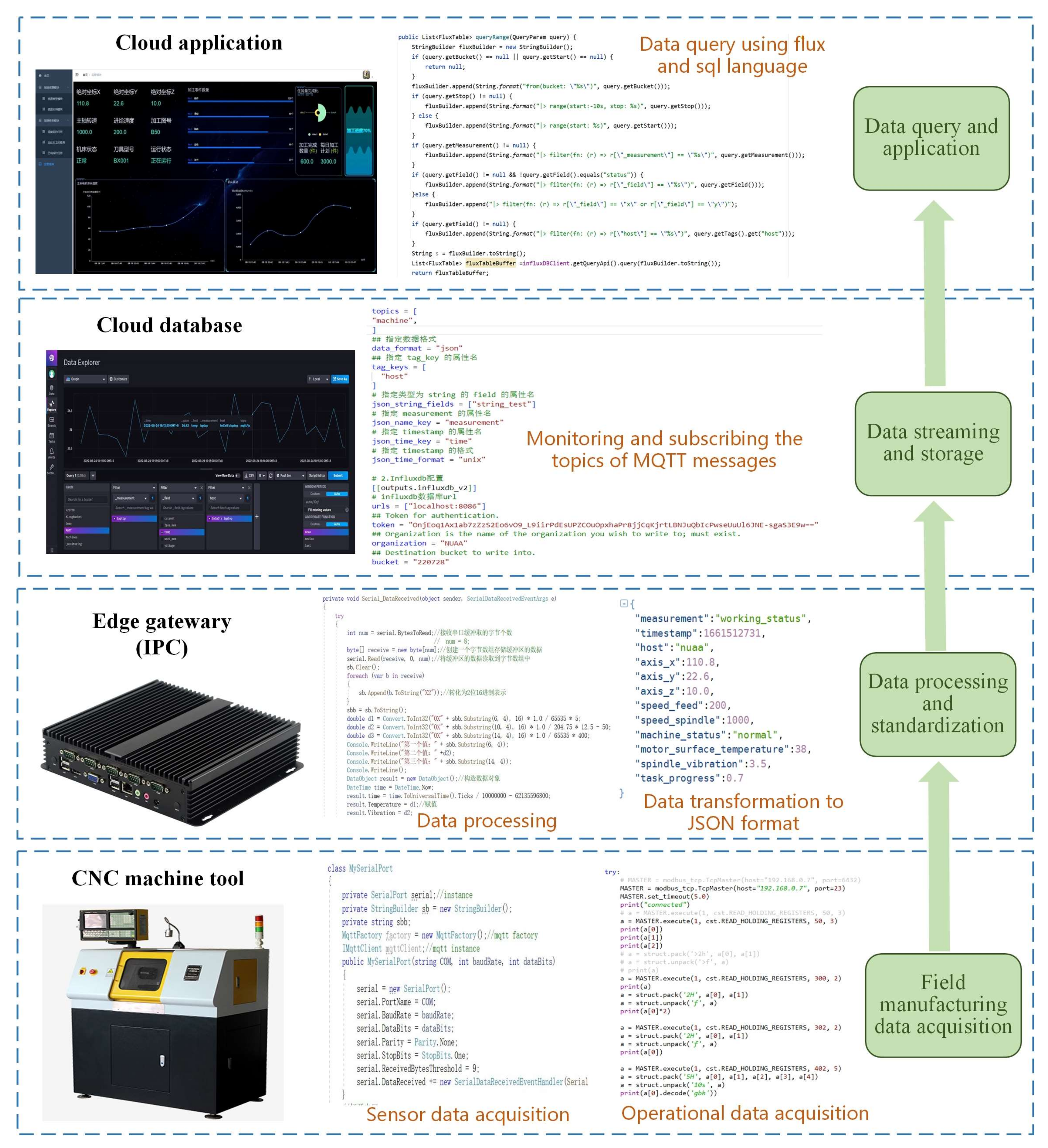
The process of data transmission and application is demonstrated in
Figure 7. Firstly, the field sensor data and operational data of CNC lathe are acquired and collected by RS485 and Modbus TCP. Secondly, the edge gateway preprocesses the collected data (i.e., outlier elimination and value conversion) and converts this data into JSON format, and the JSON files are sent to the message middleware through MQTT client. Then, the related MQTT topics are monitored and received by the cloud platform, and these data are stored in the cloud database. Finally, cloud applications use flux and SQL language to query data.
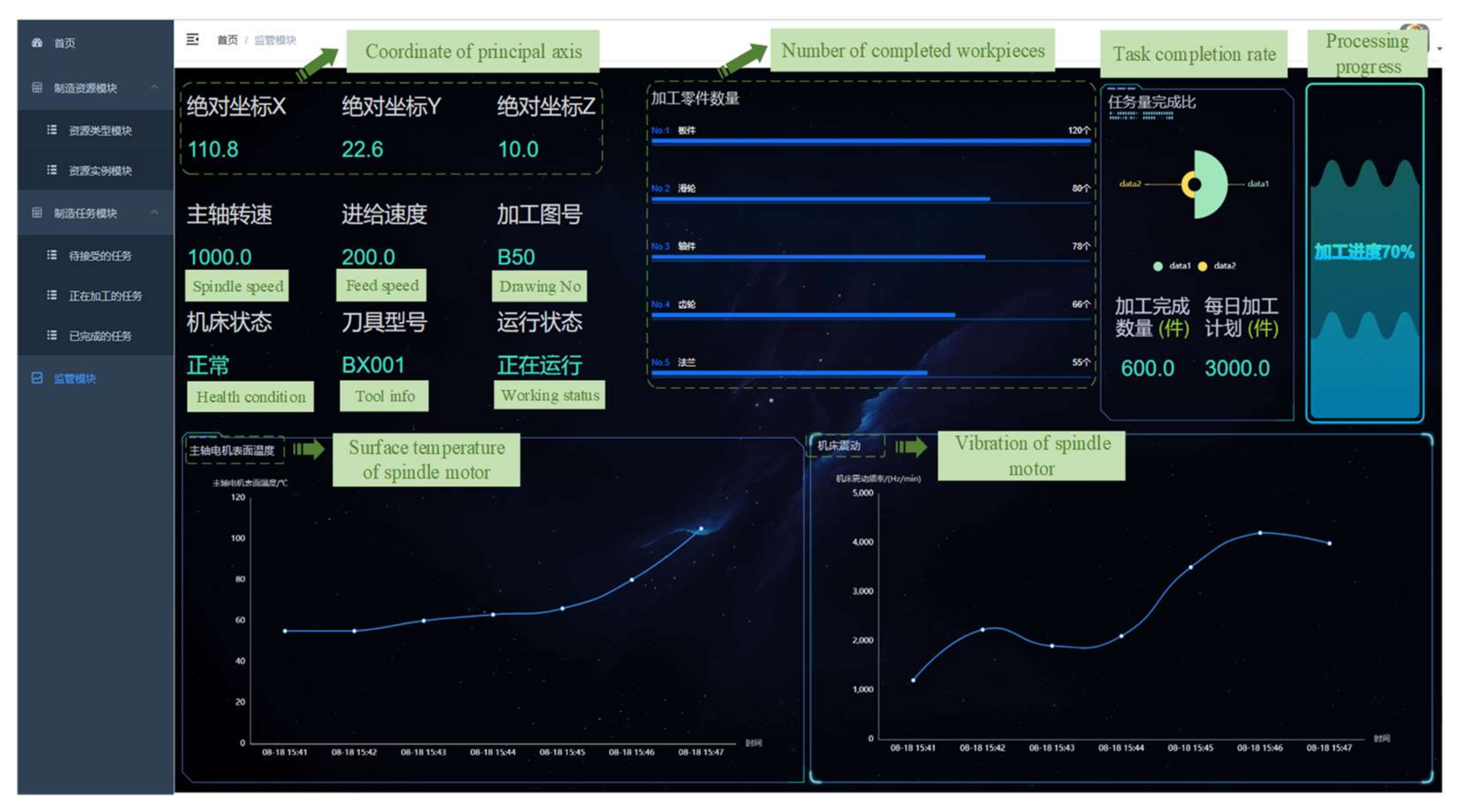
As shown in
Figure 8, the prototype system of the cloud platform is divided into homepage module, manufacturing resource module, manufacturing task module, equipment monitoring, and health management module. The manufacturing resource provider can log into the system and view the relevant information (i.e., name, type, and description) and current status (i.e., normal operation, idle, and fault) of the shared manufacturing resources in the cloud manufacturing system. In the homepage module, manufacturers can view the overall working status of manufacturing resources, including product qualification rate, number of tasks, revenue, enterprise reputation, equipment workload, and health status. The manufacturing resource provider submits the attribute information of the manufacturing resources to be shared in the manufacturing resource module, and checks the task progress and accepts new tasks in the manufacturing task module. The equipment monitoring and health management module queries the values of relevant parameters (i.e., spindle speed, task completion rate, processing progress, and motor surface temperature) by accessing the database API, and dynamically displays them on the monitoring page in the form of data curves and tables.
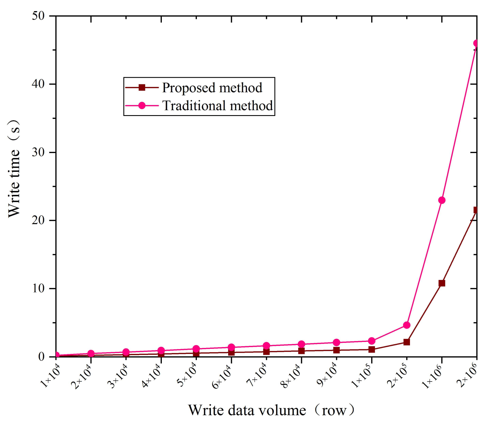
The traditional method of industrial data transmission and integration generally adopts the data storage scheme based on MySQL, while this paper proposes a hybrid data storage scheme based on InfluxDB and MySQL. In this scheme, MySQL is used to store relational data, and InfluxDB is used to store time series data. In order to verify the superiority of the proposed method, the above two schemes are used to write and store the collected data, and their performance is compared in terms of write time and storage space. The results of the data writing experiments of the two schemes are shown in
Figure 9. Under the condition that the proposed data storage method is limited by the hardware of the test computer, the data write speed can reach up to 90,000 row/s. If the hardware configuration of the test computer is upgraded, the write speed can be further improved. However, the writing speed of the traditional data storage method is maintained at about 40,000 row/s. The experiment result proves that the writing speed of the proposed method is more than twice that of the traditional method. The storage space experiment results of the two data integration schemes are shown in
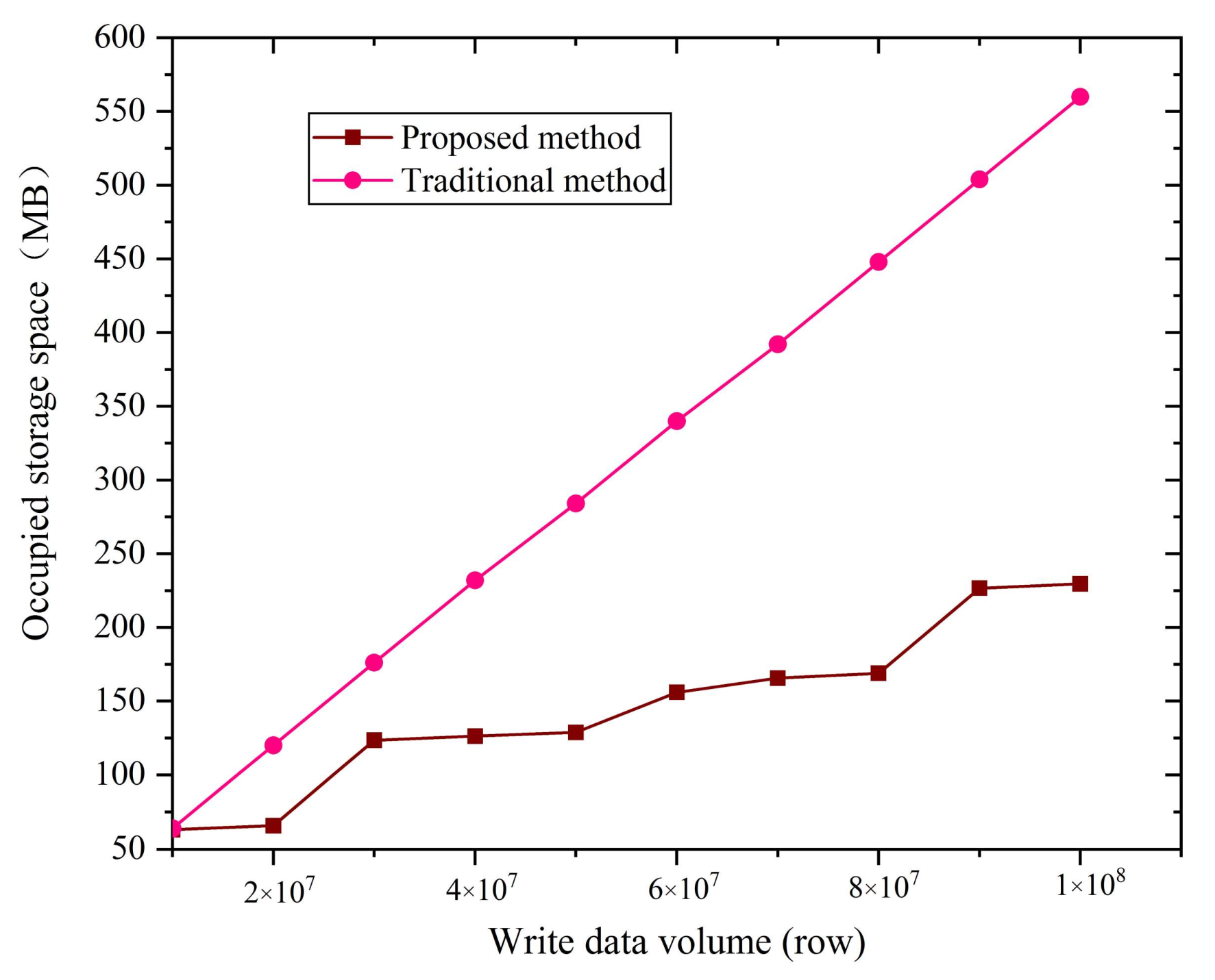
Figure 10. The proposed method can compress the collected time series data, but the traditional method cannot. When the amount of data transmitted is 1.0*108 rows, the storage space occupied by the proposed method is 235 MB, while the storage space occupied by the traditional method is 562 MB. In other words, the storage space occupied by the proposed method is obviously less than that of the traditional method, which is nearly two times larger. In summary, the proposed data acquisition and transmission method is significantly better than the traditional method in terms of writing speed and storage space.
4.2. Cloud–Edge Collaborative Updating of Artificial Intelligence Model
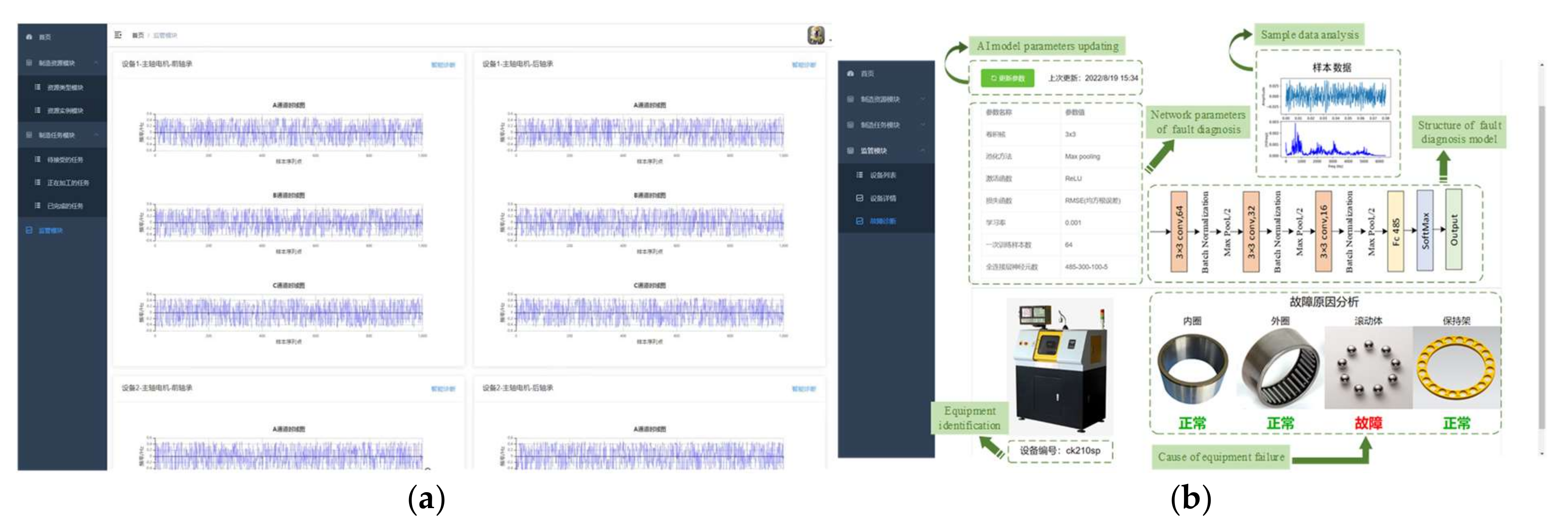
In
Figure 11, the user interface of the equipment monitoring and health management module in the cloud platform is shown in detail. For this interface, the results of the time–frequency domain analysis of vibration data are shown in
Figure 11a. The AI model updating, parameter settings, and structure of the convolutional neural network, equipment identification, and fault cause analysis are depicted in
Figure 11b.
The equipment monitoring and health management interface of the cloud platform adopts the frontend and backend separation development mode. The Springboot, Mybatis, and Springcloud frameworks are applied to develop the backend of the cloud platform. The InfluxDB and MySQL databases are used for the persistent operation of data storage. We also apply the progressive JavaScript framework (i.e., Vue) to design and build the view layer of the monitoring interface, and use an open-source JavaScript visualization library (i.e., Apache Echarts) to dynamically display temperature and vibration changes in the form of charts. The edge gateway is an industrial personal computer with 4G memory and i5-6200U CPU. The cloud platform is equipped with a cloud server with 16G memory and NVIDIA V100 GPU. Python 3.6 is used to write the code of the fault diagnosis model, and TensorFlow 1.14 is applied to build the neural network structure of fault diagnosis model.
The convolutional neural networks were applied to build the fault diagnosis model in this experiment, and this fault diagnosis model includes three convolution layers and three full connection layers. Among them, the first convolution layer adopts a convolution kernel with a size of 3 × 3, the moving step of the convolution kernel is 1, the shape of the input data is 64 × 64, the padding mode is the same, and maximum pooling is applied to compress the data. The second convolution layer adopts a convolution kernel with a size of 3 × 3, the moving step of the convolution kernel is 1, the shape of the input data is 32 × 32, the padding mode is the same, and maximum pooling is applied to compress the data. The third convolution layer adopts the same convolution kernel, moving step, padding mode, and pooling mode. The shape of its input data is 16 × 16. The fully connected layer is a three-layer neural network with 485,300,100 neurons in each layer, and the activation function is ReLU. Finally, the fault diagnosis model outputs the prediction results of five labels through the Softmax layer. The training parameters of the model are set as follows: learning rate is 0.001, batch size is 64, and the loss function is root mean square error (RMSE). The parameter updating of the fault diagnosis model will be completed after the button “model update” is clicked. The fault diagnosis model analyzes the vibration signal of the spindle motor to identify the cause of the equipment fault. In this paper, the factors leading to machine failure mainly include the inner race, outer race, ball, and holder.
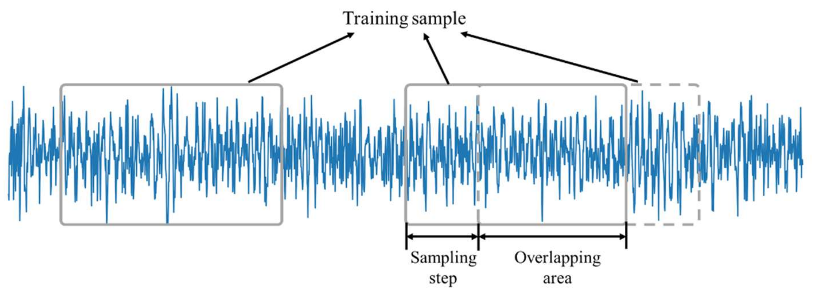
The underlying feature engineering process includes two parts: outlier elimination and data enhancement. In order to prevent abnormal data from causing error in the fault diagnosis results, the feature engineering process shall first eliminate abnormal data points. The standard deviation of the sample data is calculated, taking three times the standard deviation as the limit, and then the sample data points that exceed the limit are removed and classified as abnormal data. In the actual industry, the sample data of machine failures are very precious and rare. Therefore, data enhancement is often used to enrich the number of samples for machine failures. In this paper, the technique of overlapping sampling is applied to increase the number of samples for machine failures. As shown in
Figure 12, when the training samples are collected from the original signal, there is an overlapping area between a signal segment and the subsequent signal segment, and the sampling step is set to 1/3 of the sample length (i.e., 1024). Using this method, the number of training samples can be increased to nearly three times that of the original.
In order to better demonstrate the effectiveness of our findings, the proposed cloud–edge collaborative fault diagnosis method is compared with the edge-based method and cloud-based method in terms of three indicators (i.e., execution time, training time, and prediction accuracy). The edge-based fault diagnosis method processes and analyzes the acquired vibration data locally, and the training and updating of the fault diagnosis model are also carried out on the local server. The cloud-based fault diagnosis method uploads all of the collected vibration data to the cloud platform, then processes and analyzes these sample data through cloud applications, as well as conducts model training, and finally feeds back the prediction results of the sample data to the workshop. The proposed cloud–edge collaborative fault diagnosis method directly processes and analyzes the collected vibration data through edge applications, and uploads the preprocessed sample data to the cloud platform. The saved sample data are applied to train the fault diagnosis model and optimize the parameters by the model optimization application in the cloud platform. The parameters of the trained fault diagnosis model are periodically transmitted and sent to the edge gateway in the form of HDF5 files through the cloud–edge collaboration mechanism. The edge gateway updates and deploys the parameters of the fault diagnosis model based on HDF5 files. In this experiment, a total of 100 sample data points (including 20% fault samples and 80% normal samples) were tested for fault diagnosis, and the overall accuracies of the predicted results were taken as the evaluation indicator of model performance. In addition, the training time of the fault diagnosis model is used as another evaluation indicator.
The traditional AI model training method (i.e., edge-based) optimizes and updates the model through the terminal equipment at the edge, while the proposed method is to train the model on the cloud platform, and deploy and apply the trained model at the edge. The experimental results are shown in
Table 4. Due to the powerful GPU computing capability of the cloud platform, the proposed and cloud-based methods only take 11 min to complete the model training process. However, the traditional method (i.e., edge-based) is limited by the computing capacity of the edge server, and takes 56 min. In other words, the model training speed of the proposed and cloud-based methods is much faster than that of the traditional method. In addition, the fault prediction accuracy of the proposed method and the cloud-based method is 96%, while that of the traditional method is only 91%. The proposed and cloud-based methods only take a short time to complete the training of the AI model; therefore, the fault prediction accuracy of the AI model optimized by the proposed and cloud-based methods is higher than that of the traditional method in the same training period. The execution time represents the time consumed by the fault diagnosis model from data generation to fault prediction completion. The shorter the execution time, the better the real-time analysis performance of industrial applications. In
Table 4, the execution time of the edge-based or the proposed method is 0.8 s, while the cloud-based method consumes 4.6 s. The reason for this result is that the cloud-based method needs to transmit the generated vibration data from the equipment to the cloud platform, and then generate the prediction results through the cloud application system and feed them back to the workshop. This data transmission process consumes a lot of time.
5. Conclusions
In cloud manufacturing, the data acquisition, data transmission, and cloud access of distributed manufacturing resources are the crucial research factors that provide support for the stable operation of various machine control software and industrial applications (i.e., service matching and composition, AI model training, and remote monitoring) in the cloud platform.
With the support of the IIoT, this paper proposes a cloud–edge framework of the cloud manufacturing system, which realizes the cloud access of distributed manufacturing resources, the efficient acquisition of equipment data available at any time, and real-time data analysis and processing. Firstly, a service-oriented information model for heterogeneous manufacturing equipment is proposed, which can unify the collected heterogeneous equipment operational data and sensor data. Secondly, based on the message middleware, the running status data and related sensor data of physical equipment are transmitted and pushed from the workshop to the cloud platform, which realizes the efficient storage and ordered distribution of time series data and relational data. Finally, the training, upgrading, and deployment of the edge AI model is proposed based on cloud–edge collaboration mechanism. With the support of powerful computing ability of the cloud platform, the training speed of the AI model is greatly accelerated, and its prediction accuracy increases subsequently. With the help of the real-time data processing capability of multiple edge nodes, the response speed of the AI model deployed on the edge getaway is greatly improved. Taking a numerical control machine tool as an example, the experimental results verify the effectiveness of cloud access of distributed manufacturing resources proposed in this paper. Taking the updating of fault diagnosis AI model as an example, it is verified that the cloud–edge collaboration mechanism proposed in this paper realizes the high efficiency of the AI model training and updating methods.
In this paper, the management of edge applications lacks some flexibility, and it is impossible to directly download the complete industrial intelligence applications from the cloud, or uninstall edge applications. In the future research, the edge application management method based on microservices deserves more attention


