Article

Intramedullary Skeletal Distraction Robot: Novel Design and Optimization of Implantable Lengthening Nail

1
Department of Mechanical Engineering, Tsinghua University, Beijing 100084, China
2
State Key Laboratory of Tribology in Advanced Equipment, Beijing 100084, China
3
Beijing Key Laboratory of Precision/Ultra-Precision Manufacturing Equipments and Control, Tsinghua University, Beijing 100084, China
4
Jiangsu Key Laboratory of Special Robot Technology, Hohai University, Changzhou 213022, China
*
Author to whom correspondence should be addressed.
Machines 2022, 10(10), 843; https://doi.org/10.3390/machines10100843
Submission received: 23 August 2022 / Revised: 15 September 2022 / Accepted: 15 September 2022 / Published: 23 September 2022
(This article belongs to the Topic Advanced Electrical Machines and Drives Technologies)

Abstract

:
Leg Length Discrepancy (LLD) is a critical problem which not only impacts the quality of life but also causes other physical ailments such as limping and severe back pain. Most people had a non-negligible difference in the length of their two legs, and 0.1% of the population with differences of 20 mm or more are diagnosed as a difference in limb length. The Ilizarov external fixator is commonly used in treating LLD as conventional therapeutic equipment, but often causes serious complications that cannot be prevented. Therefore, intramedullary leg-lengthening treatment has become popular in distraction osteogenesis to eliminate extracorporeal surgery. This paper presents a study on the design and optimization of a novel electromagnetic-driven Intramedullary Skeletal Distraction Robot (ISDR) with robust mechanical stiffness and surplus electromagnetic driving force. Compared with PRECICE, the split structure of ISDR eases the optimal design and manufacturing difficulties to strengthen mechanical stiffness, and the electromagnetic configuration allows improving the distraction force by adjusting the Permanent Magnet Brushless Direct Current (PMBLDC) motor parameters. ISDR, which is implanted in the medullary cavity, has the Von-Mises stress of 952.15 MPa, and the first mode of natural frequency is 28.823 Hz indicating that it can withstand the load during the walking gait phases. On the other hand, the ISDR distraction force encounters resistance from muscle fibers, and an average driving torque of 9 Nmm ensures its distraction. Based on the results, ISDR is proven secure and reliable during and after leg-lengthening treatment, which can significantly reduce lifestyle disruption and medical complications.

1. Introduction

Leg Length Discrepancy (LLD), also known as anisomelia, is a condition of noticeably unequal length of the paired lower extremity limbs that is commonly caused by congenital, developmental, or posttraumatic conditions, such as trauma from birth, the malformed socket of the hip joint, and arthritis of the joints [1]. Abnormal growth, hip dysplasia, scoliosis, limping, back pain, and osteoarthritis have been deemed the complications of LLD [2]. Guichet et al. found that 0.1% of the population went for surgery when the difference in leg length exceeded 2 cm [3]. Generally, the methods frequently used in the clinical treatment of LLD include non-surgical treatment (wearing a shoe lift) and surgical treatment (shortening longer limbs or lengthening shorter limbs) [4]. However, limb shortening is disallowed in some instances since it leads to muscle weakening.
An orthopedic surgeon, Gavriil A. Ilizarov, proposed the theory of tensions, which has become the fundamental principle in limb lengthening and reshaping treatment. According to this theory, the Ilizarov external fixator was widely promoted in the 1980s and gradually became the primary treatment apparatus in this field, which showed revolutionary results [5]. However, the Ilizarov external fixator has accentuated the problem of inconvenience and discomfort that may cause certain complications such as pin site infection, axial deviation, joint stiffness, soft tissue incarceration, and delayed union of the docking site [6,7,8,9]. As a result, an implantable lengthening nail (ILN) [10] was invented to solve these issues.
The implantable lengthening nail is a kind of intramedullary distraction device that has been widely used in limb lengthening and replaced the mainstream therapy apparatus due to its effectiveness in treating LLD without complications. The first implantable lengthening nail, the Bliskunov intramedullary nail, was driven by a mechanical ratchet system and controlled via the rod bolted to the pelvis [5]. Baumgart et al. proposed a motorized implantable lengthening nail with a subcutaneous antenna, where the electric currents for powering the motor are generated via an induction method [11,12]. However, the wire between the antenna and the motor might fail to function due to daily routine or tissue fluid corrosion.
The Orthofix company designed an implantable lengthening nail, the Intramedullary Skeletal Kinetic Distractor (ISKD), which has a magnet encased within the tip of the threaded rod showing a new driving mechanism concept. However, the Food and Drug Administration (FDA) banned ISKD from the market because of its unstable and uncontrollable distraction rate [13,14,15,16,17]. A. Soubierian proposed an internal rotating magnet implantable lengthening nail (Phenix) driven by the circular motion of a hand-held magnet around the limb. Even though Phenix demonstrates outstanding clinical results, it is less known [18].
The NuVasive company designed an internal magnet implantable lengthening nail and two external magnets housed in a computer-controlled power assembly. PRECICE (P1), a welded-split structure implantable lengthening nail, was the first implantable lengthening nail marketed in the United States. However, P1 was unbearable for weight-bearing, resulting in a rift appearing at the welding part after implantation [16]. Therefore, an upgrade version of P1, PRECICE2 (P2), utilized a seamlessly connected structure, giving higher bending strength than P1 [10,17]. P2 achieved great accomplishment in LLD clinical treatment but still had some shortcomings, e.g., full weight-bearing before the consolidation phase is prohibited and temporarily decelerating or stopping distraction [19,20]. NuVasive’s latest and largest weight-bearing implantable lengthening nail, PRECICE STRYDE, allowed the patient to proceed with their daily routine quicker. Yet, its material was unendurable to tissue fluid, and its non-hermetically seal design corroded the internal and external of the implantable lengthening nail [21,22,23,24]. Despite its remarkable success, several problems still exist in PRECICE, such as insufficient rigidity, unreliable distraction rate, and material corrosion.
In this study, we propose an implantable lengthening nail based on an electromagnetic configuration, Intramedullary Skeletal Distractor Robot (ISDR). ISDR possesses a high reduction ratio (exceeding 150), large distraction force (exceeding 1000 N), and sturdy structure stiffness characteristics for treating LLD. The essay is organized in the following way. Section 2 describes the electromagnetic configuration synthesis in terms of the human lower extremity and presents the conceptual design of the ISDR. Next, Section 3 investigates the mechanical stiffness and distraction forces that commonly trouble the clinician during limb lengthening. Section 4 shows the simulation and experiment results of the designed ISDR, while Section 5 optimizes the electromagnetic properties. Finally, Section 6 concludes.

2. Configuration Synthesis of ISDR

In this section, the configuration synthesis of ISDR is investigated by setting its design guidelines based on lower extremity characteristics for conceptual design.

2.1. Design Guidelines for ISDR Based on Human Lower Extremity Characteristics

According to medical reports, the diameter of the femur in Asian men is 11.08 ± 1.9 mm, the length of the femur is 418 ± 20 mm, and the circumference of the thigh is 53.9 ± 6.3 cm [25,26]. Ji et al. showed that the frequency of men walking has a range of 1.77 ± 0.36 Hz [27]. The values of the lower extremity are chosen nearly to their extreme value for general purpose (listed in Table 1).
Generally, the human walking gait cycle is divided into six phases: heel strike (HS), foot-flat (FF), mid stance (MS), heel-off (HO), toe-off I (TO-I), and toe-off II (TO-II) [28] (shown in Figure 1). The maximal force occurs during the MS phase, around 40% to 60% of the stance phase [29]. Based on this, we estimate the forces acting on the femur in three directions (frontal force, lateral force, and axial force) among six phases, as listed in Table 2.
On the basis of these prerequisites, the priority of ISDR design guidelines is the body characteristics. After setting design guidelines, the driving method becomes our main concern. Although magnetic configurations achieve massive success in treating LLD, the limitation of external magnets is that their properties are unadjustable in various cases. Therefore, in this study, electromagnetic configurations are used in designing ISDR.

2.2. Conceptual Design of ISDR

The configuration of the intramedullary lengthening nail system includes two parts: an implantable lengthening nail implanted inside the medullary canal and an internal magnet driver placed outside the limb. The internal magnet driver generates rotating magnetic fields that spin the permanent magnet of the implantable lengthening nail to endow a force for bone distraction.
Clinicians make an incision near the hip joint and femoral shaft before implanting the implantable lengthening nail into the limb. Then, they use a cannulated drill to enlarge the medullary canal to facilitate implantation. After completing the enlargement procedure, they apply an osteotomy by using the osteotome, followed by the insertion of the implantable lengthening nail into the medullary canal and fixed tightly by bone screws at both the upper and lower ends. Once the clinicians complete implantation surgery, they can place the internal magnet driver near the limb to drive the implantable lengthening nail magnet for treating LLD.
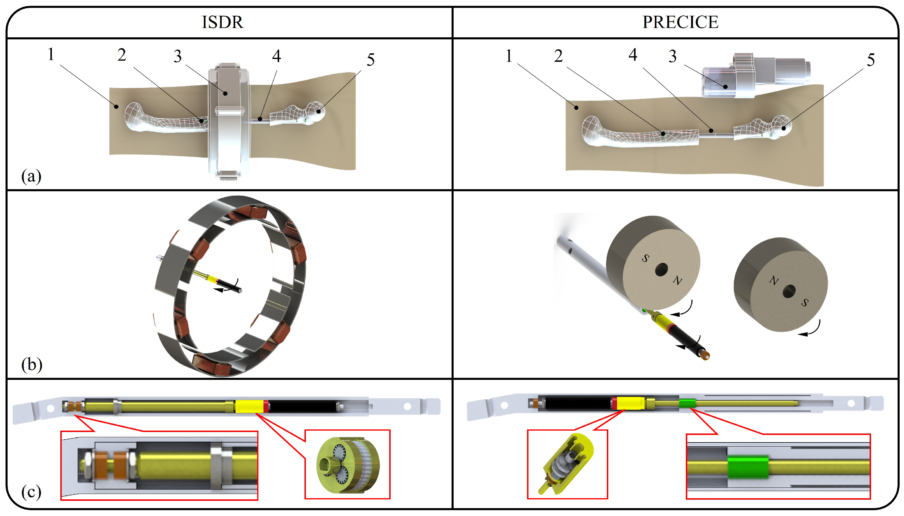
There are some differences between ISDR and PRECICE (Figure 2a–c). PRECICE places its permanent magnet near the proximal femoral shaft, while ISDR places its permanent magnet near the distal femoral shaft. This design signifies that the air gap between the permanent magnet and the driver is minor, revealing the driving torque for the bone distraction is much more stable and forceful. Moreover, the transmission component of ISDR has a longer lifespan compared to PRECICE because the transmission of the axial load from the distraction nail towards the thrust bearing and protective shell occurs without passing through the gearbox. Last but not least, the distraction force of ISDR is adjustable and controllable by tuning the electromagnetic driver parameters akin to the Permanent Magnet Brushless Direct Current (PMBLDC) motor model.

2.2.1. Implantable Lengthening Nail

Figure 3 illustrates that the proposed implantable lengthening nail distraction mechanism is well-protected by a protective shell. The mechanical stiffness of implantable lengthening nail is guaranteed by a titanium alloy with good bio-compatibility (non-toxic and high resistance to oxidization), lightweight, and rigid characteristics, which is commonly used in surgical transplants [30,31,32].
The implantable lengthening nail adopts a distraction structure design, where the distraction mechanism is placed within the distraction nail. The distraction mechanism consists of an internal permanent magnet, a gearbox that can be either a planetary gearbox or Rotate Vector (RV) gearbox, a lead screw, and its nut. The end of the lead screw is connected to the shafting system, which is fit or screwed tightly into the protective shell. This design provides a rotational degree of freedom for the lead screw, and its nut moves freely along with the distraction nail inside the protective shell since they are transition fit. The screw holes are designed in conventional patterns at both ends of the protective shell and distraction nail for fixation on the extremity medullary canal.
Once the electromagnetic driver is energized, the rotating magnetic field starts to drive the internal permanent magnet to rotate. The driving torque is amplified by the gearbox and transmitted to the lead screw. The thrust bearing is placed on the shafting tube so that the axial load acts directly on the protective shell without passing through the distraction mechanism. The distal bone begins to distract with the assistance of the distraction nail, meaning bone lengthening occurs as long as sufficient torque is provided.

2.2.2. Electromagnetic Driver

The electromagnetic driver acts as a PMBLDC motor stator group, providing the external rotating magnetic field required to drive the internal permanent magnet, as shown in Figure 4.
The electromagnetic driver mainly consists of a stator core, self-tapping screws, nylon protective layers, and copper wire coils. The electromagnetic driver is designed as a tuck-in design for the convenience of wearing. The stator core and middle nylon protective layer are attached firmly by screwing them together with the self-tapping screws. The function of the nylon protective layer is to prevent the sharp edges of silicon steel sheets from accidentally cutting the patient or current leakage. Copper wire coils wind around the stator core slot with a distributed half-coiled pattern. The upper and lower nylon protective layers are screwed after winding, forming a closed ring structure.

3. Mechanics and Dynamics Evaluation Index of ISDR

In this section, the mechanics and dynamics of ISDR are evaluated via mechanical stiffness and torques, and mechanistic indexes are quantitatively simulated by finite element analysis (FEA).

3.1. Mechanical Stiffness of the Lengthening Nail

Mechanical stiffness is determined by examining that the product stress value is lower than its material yield tensile strength. Therefore, the mechanical stiffness of implantable lengthening nails is verified via FEA, which is frequently used in computer-aided engineering (CAE) [33,34] to ensure its capability for withstanding forces under walking gait phases.
FEA is an approximating function (Interpolating functions/Shape functions) that expresses the unknown field variables by dividing the solution regions into small elements [35]. The Von-Mises stress obtained via FEA must not exceed the material yield tensile strength, which can be written as [36]:
σ [ σ ] ,
where σ is the Von-Mises stress, and [ σ ] is the yield tensile strength.
On the other hand, the dynamic behavior is determined via modal analysis in the patterns of damping factors, natural frequencies, and mode shapes [37]. Resonant damage must be avoided as it shortens the lifespan of implantable lengthening nails and thus endangering the patient. Hence, the walking frequency of the patient must keep away from the natural frequency range of implantable lengthening nails. With the aid of FEA, the natural frequency of implantable lengthening nails is also determined.

3.2. Torques of ISDR

3.2.1. Lifting Torque for Bone Distraction by Implantable Lengthening Nail

The distraction force of ISDR is a crucial indicator when the clinician is treating LLD. Based on the research work of Zhang et al. [38], the distraction rate in the range of 0.91 ± 0.41 mm/day is more effective for the treatment. On the other hand, the distraction period (days) relates logarithmically to the distraction force of body mass (N/kg) [39]. In other words, if the body mass is heavier or the distraction period is longer, surgery failure is more likely to happen due to insufficient distraction force.
Sufficient lifting torque is a must to achieve the distraction force required. The lifting torque T L for a lead screw can be written as follows [40]:
T L = F d m 2 l + π μ d m π d m μ l ,
where F is the distraction force, d m is the mean diameter, μ is the coefficient of friction for the thread, and l is the screw lead.
Due to the presence of the planetary gearbox, even with some efficiency loss in the planetary gearbox, the driving torque generated from the electromagnetic driver is much smaller than the required lifting torque. Therefore, the driving torque T D is obtained in terms of Equation (3) [41,42,43]:
T D = T L · 1 e 1 i 1 · 1 e 2 i 2 1 e n i n ,
where e is efficiency, i is reduction ratio, and n is the number of stages. The driving torque T D is rewritten as Equation (4) since the reduction ratio and efficiency of the planetary gearbox in each stage are equal. The relationship between lifting torque, driving torque and distraction force are illustrated in Figure 5 for better understanding.
T D = T L · 1 ( e i ) n .
Although reduction ratio and the number of stages are effective ways of improving the distraction force, the total weight of the implantable lengthening nail became heavier. Hence, raising the driving torque of the electromagnetic driver is an alternative method.

3.2.2. Driving Torque for Actuation by Electromagnetic Driver

The electromagnetic driver and internal permanent magnet combination are equivalent to PMBLDC motors since their rotors rotate synchronously when the stator provides a rotating magnetic field. Therefore, the equations for the PMBLDC motor are fully applicable to the electromagnetic driver [44]. The torque of the PMBLDC motor is described as:
T D = 2 P B g I s n s L R s i ,
where P is the number of poles, B g is the air gap flux density in the middle 120 of a pole, I s is the DC source current, n s is the number of turns per slot, L is the active length of the motor, and R s i is the stator inner radius. Based on Equation (5), source current and number of turns are the most productive way of driving the torque increment. Yet, these variables are insufficient to determine the geometric parameters of the electromagnetic driver, so their relations with torque are given by:
A s l o t = 1 2 ( w s t + w s b ) d s = n s K f i l l A C u ,
A C u = π d C u 2 4 ,
where A s l o t is the slot area, w s t is the top slot width, w s b is the bottom slot width, d s is the slot depth, K f i l l is the slot fill factor, A C u is the coil cross-sectional area, and d C u is the copper wire diameter. In the meantime, the remaining geometric parameters in the stator core are obtainable from the function of three geometric parameters in the slot area.
τ s l o t = 2 π R s i N s l o t ,
τ c = 2 π R s i + 1 2 d s 1 P ,
w s b = τ s l o t w t ,
d s = R s o R s i 1.5 w b i ,
w s t = 2 π ( R s i + d s ) N s l o t w t ,
where τ s l o t is the slot pitch, N s l o t is the number of slots, τ c is the coil pitch, w t is the tooth width, R s o is the stator outer radius, and w b i is the back iron length. These geometric parameters are presented in Figure 6.

4. Simulation and Experimental Validation

In this section, both mechanical stiffness and torques are analyzed and simulated while the driving torque is tested with the torque measurement system.

4.1. Analysis and Simulation of Mechanical Stiffness

Referring to the characteristics given in Table 1, the implantable lengthening nail is designed according to the parameters listed in Table 3.
The implantable lengthening nail starts to distract along with the distal bone after clinicians perform an osteotomy. In our case, the maximal allowable distraction length showed an 80 mm gap between the proximal and distal bone at the end of the distraction period and before the consolidation phase (shown in Figure 7). Three principal forces acting on the femur throughout six gait phases (shown in Table 2) are applied at the lateral and medial condyle, while fixed support is applied at the femoral head. FEA is used to examine the implantable lengthening nail maximal stress and minimal natural frequency.
According to the results of Table 4 and Figure 8, we noticed that the highest value of Von-Mises Stress occurs around the 80 mm gap, especially during the fifth phase of the walking gait cycle (around 952.15 MPa). The material has a slightly higher yield tensile strength (1100 MPa) than the maximal stress, so it is encouraged to use a crutch before the consolidation phase. Based on the boundary condition given for the static structure, the basis natural frequency is 28.823 Hz, a much larger value than the walking frequency (2 Hz), as shown in Table 5.

4.2. Analysis and Simulation of Torques

4.2.1. Lifting Torque of Implantable Lengthening Nail

The distraction rate commonly used by clinicians is 1 mm/day, and the distraction force of body mass is around 9.5 N/kg at the end of the distraction period (80 days) [39]. Therefore, we refer to the bodyweight in Table 1 and obtain the minimum distraction force required is 665 N. However, a safety factor should be considered since the distraction force of body mass might vary among the patients. So, the safety factor is set to 1.5, which gives the final distraction force of approximately 1000 N.
The geometric sizes of the M6 lead screw d m = 5.1 mm, l = 0.75 mm, and μ = 0.1 are substituted into Equation (2), giving us a value of lifting torque of 376.1 Nmm. Once the lifting torque is confirmed, we can compute the driving torque required for bone distraction via Equation (4). Generally, the efficiency of planetary gear per stage is e = 0.97 , giving us a driving torque of approximately 2.721 Nmm, which indicates the minimum value to guarantee the distraction.

4.2.2. Driving Torque of Electromagnetic Driver

According to the design guidelines set in Section 2, we design a three-phase six salient poles stator core to serve as the electromagnetic driver and two magnet poles to be used as the internal permanent magnet of the implantable lengthening nail. The design specifications of the electromagnetic driver components are listed in Table 6.
A microcontroller and, alternatively, analog or digital circuits can implement the commutation of PMBLDC motor current source even if it is a DC. The PMBLDC motor commutation order is one winding energized positive, one winding energized negative, and one winding non-energized. According to the wire gauge standard, an allowable current for a 1.725 mm diameter wire is 9.2 A. Based on safety and power consumption considerations, we restrict the electric current of the electromagnetic driver to around 7 A, which turned out to be sufficient to generate the driving torque.
Some parameters of the PMBLDC motor model shown in Equation (5), such as the active length of the motor and the inner radius of the stator core, are highly dependent on the lower extremity characteristic. Therefore, the DC source current and number of turns have become the key factors to adjust the driving torque. After trial and error in adjusting these parameters, the simulation showed that the average driving torque of the magnetic drive is 8.2 Nmm (shown in Figure 9) which is extremely large compared to the minimum lifting torque of 2.721 Nmm.

4.3. Experiment Validation of Driving Torque

A simple driving torque experiment is conducted, and the experimental setup is shown in Figure 10. A microcontroller unit is adopted to control the commutation order of the stator core while the power supply powers them. The permanent magnet is erected in the middle of the stator core. As soon as the external rotating magnetic field is generated, a torque measurement system is utilized to measure the driving torque, and the computer records the following data.
The maximum and minimum values of experimental driving torque data are around 9.8 Nmm, and 4.9 Nmm, respectively, and its average value is about 6 Nmm, as shown in Figure 11. The reasons that cause differences in both outcomes may be the frictional force in the permanent magnet shaft, the copper winding is winded manually, the permanent magnet is not in the center position, and the torque measuring system is handheld. The driving torque can be measured more accurately if the problem stated is completely solved.

5. Optimization of the Electromagnetic Driver Design

Although the driving torque is sufficient for bone distraction, there are sacrifices in the electromagnetic driver’s overall weight and power loss. Therefore, the genetic algorithm (GA) procedure is introduced to achieve the optimal value of driving torque.

5.1. Problem Formulation

The goal is to find the optimum geometric parameters by minimizing the objective function when the requirements are satisfied. The main emphasis of electromagnetic drivers is driving torque capability, followed by the apprehension of wearable design overall weight and the PMBLDC motor model power loss. In addition to these criteria, other objectives such as magnetic flux leakage and cogging torque minimization are also suitable for optimization.
Generally, the objectives are reorganized into a mathematical expression as a function of geometric parameters. As mentioned above, these objective variables are driving torque ( T D ), overall weight ( W t o t a l ), and power loss ( P t o t a l ). The driving torque of the electromagnetic driver is reconstructed as a relation with geometric parameters by referring to Equations (5)–(7):
T D = K m I s ( w s t + w s b ) d s A C u ,
where K m = P B g L R s i K f i l l . These geometric parameters are further replaced by back iron length ( w b i ), number of slots ( N s l o t ), and tooth width ( w t ) as is shown in Equations (8)–(12). Hence, these basic parameters and the copper wire diameter ( d C u ) are selected as the variables of driving torque, namely the genes in a chromosome for the GA procedure.
The overall weight of the electromagnetic driver is obtained by summing the mass of the stator core and the copper winding together, after multiplying steel density and copper density with their volume, respectively. Since the dimensions of the stator core and copper winding rely on the electromagnetic driver geometry, the following expression is written:
W = W F e + W C u = ρ F e V F e + ρ C u V C u ,
V F e = π ( R s o 2 R s i 2 ) L N s l o t A s l o t L ,
V C u = n s N s l o t A C u ( L + τ c ) ,
where W F e is the mass of silicon steel sheet, W C u is the mass of copper winding, ρ F e is the density of silicon steel sheet, and ρ C u is the density of copper. After that, the substitution of variables is conducted to achieve the identical variable as the driving torque.
On the other hand, power loss of the PMBLDC motor model is divided into three categories: electrical, magnetic, and mechanical [45]. Mechanical loss is negligible in the power loss since efficiency loss in the planetary gearbox and safety factors were previously considered in the lifting torque. Thus, electrical loss and magnetic loss are discussed here. Electrical loss originates from the resistance of copper winding as well as magnetic loss comes from hysteresis and eddy current losses, which vary nonlinearly with frequency and magnetic flux density [44]. The power loss is obtained through the summation of electrical loss and magnetic loss, as shown in the equation below.
P = P e l e c + P m a g ,
P e l e c = 3 I s 2 P n s ζ C u ( L + τ c ) A C u ,
P m a g = L ( f , B m a x ) W F e ,
and
I s = v r = v A C u N s l o t 12 ζ C u n s ( L + τ c ) ,
where P e l e c is the electrical loss, P m a g is the magnetic loss, ζ C u is the resistivity of copper, L ( f , B m a x ) is the core loss of silicon steel, v is the source voltage, and r is the resistance of each phase. The geometric parameters are changed to typical variables in driving torque.

5.2. Optimization Procedure

5.2.1. Objective Functions

The optimization variables that need to be optimally discovered are selected and represented as a vector of x. As the previous section mentioned, the basic parameters are chosen as the optimization variables, which can be written as follows:
x = [ w b i N s l o t w t d C u ] T .
The lower and upper bound values of each variable are set, which are denoted as x m i n and x m a x , respectively. The pattern of an objective function may vary according to the application and requirement of the PMBLDC motor. In this paper, the objective function comprises the overall weight, power loss, and inverse of the driving torque that are meant to be minimized. Both weighting factors and normalization are considered in the objective function to adjust the significance of each objective and scale their values to an equivalent order of magnitude.
min f ( x ) = λ 1 T d 0 T d ( x ) + λ 2 W ( x ) W 0 + λ 3 P ( x ) P 0 ,
where λ 1 , λ 2 and λ 3 are the weighting factors, T d 0 , W 0 and P 0 are the randomization values of driving torque, overall weight and power loss, respectively.
Apart from determining the objective function, constraints are added based on the PMBLDC motor limitations of heat, electrical and mechanical energy. Since the copper wire diameter is an optimization variable, the source current is set as an inequality constraint that satisfies the allowable current for a particular wire gauge. Hence, the following objective function is rewritten as [45]:
min f ( x ) = λ 1 T d 0 T d ( x ) + λ 2 W ( x ) W 0 + λ 3 P ( x ) P 0 + 1 ϵ f u ( 1 I a l l o w I s ) ,
where ϵ is a small constant, I a l l o w is the allowable current for a specific wire gauge, and
f u ( x ) = 1 1 + e σ x ,
where σ is a large constant. The penalty function is introduced in Equation (24) to override the multi-objective function result whenever I s exceeds I a l l o w giving larger values that deviate from the local or global optimum.

5.2.2. Genetic Algorithms

GA is an evolutionary algorithm that aims to find the optimal solution based on inspiration from a natural selection such as selection, crossover, and mutation, which are discovered in nature [46]. An individual represents the solution domain, and a fitness function evaluates the solution domain.
First, the values of the objective parameters are randomly selected within their limits to form the initial populations for minimizing the objective functions by examining the fitness value. If the fitness value satisfies the stopping criterion, the procedure ends immediately. On the contrary, new populations are formed by selection, crossover, and mutation in each generation and adopted in the upcoming iterations until the fitness value is optimally found or reaches the maximum number of iterations. The fittest parameters are utilized in the electromagnetic driver to promote its performance. The flowchart of a simple GA procedure is shown in Figure 12.

5.3. Optimization Result

Before solving the optimization problem, the constant parameters and optimization technical parameters needed for initialization of the objective function are listed in Table 7. The lower and upper bounds of the optimization variables are confirmed, which contributed to the optimum value, see Table 8. Other characteristics of the optimized stator core are listed in Table 9. The geometric parameters and variables from the GA procedure are utilized in the simulation and gave the results shown in Figure 13 and Table 10.
As attested by the results, the performance of the electromagnetic driver shows significant improvement in driving torque and power loss by adjusting the stator core slot area, the number of turns, and the copper wire diameter. Nevertheless, the total weight increases but is still in the acceptable range. Moreover, we notice that the start-up takes more time than the previous one, but it is not the primary concern. Overall, the electromagnetic driver becomes more efficient than before optimization.

6. Conclusions

In this paper, we proposed an inverted distraction structure design implantable lengthening nail where the internal permanent magnet is placed nearer to the distal femoral shaft, which enables it to receive the driving torque without effort. Furthermore, the magnetic configuration is substituted with an electromagnetic one for ease of controlling the driving torque required for bone distraction. To this end, we designed an implantable lengthening nail and its electromagnetic driver based on the human lower extremity. Then, the mechanical stiffness of the implantable lengthening nail is verified by simulating the human walking gait cycle granting us a value of nearly 950 MPa. Next, the lifting torque required for the implantable lengthening nail to conduct bone distraction is calculated, followed by analyzing and experimenting with the driving torque of the electromagnetic driver. Lastly, the parameters of the electromagnetic driver are adjusted via the genetic algorithm to improve its driving torque to 9 Nmm, which is increased by 8.89% compared with the trial and error method.
In conclusion, the proposed ISDR meets the requirements that clinicians are eager for, but a crutch is recommended to avoid unpredictable accidents. In future works, we will manufacture the prototype of ISDR and verify its capability. In addition, an animal experiment will be conducted to prove its effectiveness in treating LLD.

Author Contributions

Conceptualization, Z.N. and X.-j.L.; methodology, S.L. and Z.N.; formal analysis and validation, S.L. and K.H.; investigation, S.L. and Z.N.; resources, Z.N., F.X. and X.-j.L.; data curation, S.L., Z.N. and H.X.; experiment and validation, H.X. and H.L.; writing—original draft preparation, S.L.; writing—review and editing, Z.N. and H.X.; visualization, S.L.; supervision, Z.N., F.X. and X.-j.L.; project administration, Z.N. and X.-j.L.; funding acquisition, Z.N., F.X. and X.-j.L. All authors have read and agreed to the published version of the manuscript.

Funding

This work is supported by Zhongguancun (ZGC) open laboratory proof-of-concept (POC) projects under Grant 20210421084.

Data Availability Statement

Not applicable.

Conflicts of Interest

The authors declare no conflict of interest.

References

  1. Shi, B.; Shu, H. Research progress of fully implantable intramedullary lengthening nail. Chin. J. Orthop. 2019, 12, 58–64. [Google Scholar]
  2. Vogt, B.; Gosheger, G.; Wirth, T.; Horn, J.; Rödl, R. Leg length discrepancy—Treatment indications and strategies. Dtsch. Ärzteblatt Int. 2020, 117, 405–411. [Google Scholar] [CrossRef] [PubMed]
  3. Guichet, J.M.; Spivak, J.M.; Trouilloud, P.; Grammont, P.M. Lower limb-length discrepancy. An epidemiologic study. Clin. Orthop. Relat. Res. 1991, 272, 235–241. [Google Scholar] [CrossRef]
  4. Steen, H.; Terjesen, T.; Bjerkreim, I. Anisomelia. Clinical consequences and treatment. Tidsskr. Nor. Laegeforen. Tidsskr. Prakt. Med. Raekke 1997, 117, 1595–1600. [Google Scholar]
  5. Birch, J.G. A brief history of limb lengthening. J. Pediatr. Orthop. 2017, 37, S1–S8. [Google Scholar] [CrossRef]
  6. Fragomen, A.T.; Miller, A.O.; Brause, B.D.; Goldman, V.; Rozbruch, S.R. Prophylactic postoperative antibiotics may not reduce pin site infections after external fixation. HSS J. 2017, 13, 165–170. [Google Scholar] [CrossRef]
  7. Bhave, A.; Shabtai, L.; Woelber, E.; Apelyan, A.; Paley, D.; Herzenberg, J.E. Muscle strength and knee range of motion after femoral lengthening: 2-to 5-year follow-up. Acta Orthop. 2017, 88, 179–184. [Google Scholar] [CrossRef]
  8. Kazmers, N.H.; Fragomen, A.T.; Rozbruch, S.R. Prevention of pin site infection in external fixation: A review of the literature. Strateg. Trauma Limb Reconstr. 2016, 11, 75–85. [Google Scholar] [CrossRef]
  9. Liu, Y.; Yushan, M.; Liu, Z.; Liu, J.; Ma, C.; Yusufu, A. Complications of bone transport technique using the Ilizarov method in the lower extremity: A retrospective analysis of 282 consecutive cases over 10 years. BMC Musculoskelet. Disord. 2020, 21, 354. [Google Scholar] [CrossRef]
  10. Paley, D. PRECICE intramedullary limb lengthening system. Expert Rev. Med. Devices 2015, 12, 231–249. [Google Scholar] [CrossRef]
  11. Black, S.R.; Kwon, M.S.; Cherkashin, A.M.; Samchukov, M.L.; Birch, J.G.; Jo, C.H. Lengthening in congenital femoral deficiency: A comparison of circular external fixation and a motorized intramedullary nail. J. Bone Jt. Surgery. Am. Vol. 2015, 97, 1432–1440. [Google Scholar] [CrossRef]
  12. Accadbled, F.; Pailhé, R.; Cavaignac, E.; de Gauzy, J.S. Bone lengthening using the Fitbone® motorized intramedullary nail: The first experience in France. Orthop. Traumatol. Surg. Res. 2016, 102, 217–222. [Google Scholar] [CrossRef] [Green Version]
  13. Cole, J.D.; Justin, D.; Kasparis, T.; DeVlught, D.; Knobloch, C. The intramedullary skeletal kinetic distractor (ISKD): First clinical results of a new intramedullary nail for lengthening of the femur and tibia. Injury 2001, 32, 129–139. [Google Scholar] [CrossRef]
  14. Lee, D.H.; Ryu, K.J.; Song, H.R.; Han, S.H. Complications of the Intramedullary Skeletal Kinetic Distractor (ISKD) in distraction osteogenesis. Clin. Orthop. Relat. Res. 2014, 472, 3852–3859. [Google Scholar] [CrossRef]
  15. Mahboubian, S.; Seah, M.; Fragomen, A.T.; Rozbruch, S.R. Femoral lengthening with lengthening over a nail has fewer complications than intramedullary skeletal kinetic distraction. Clin. Orthop. Relat. Res. 2012, 470, 1221–1231. [Google Scholar] [CrossRef]
  16. Schiedel, F.M.; Vogt, B.; Tretow, H.L.; Schuhknecht, B.; Gosheger, G.; Horter, M.J.; Rödl, R. How precise is the PRECICE compared to the ISKD in intramedullary limb lengthening? Reliability and safety in 26 procedures. Acta Orthop. 2014, 85, 293–298. [Google Scholar] [CrossRef]
  17. Paley, D.; Harris, M.; Debiparshad, K.; Prince, D. Limb lengthening by implantable limb lengthening devices. Tech. Orthop. 2014, 29, 72–85. [Google Scholar] [CrossRef]
  18. Thaller, P.H.; Fürmetz, J.; Wolf, F.; Eilers, T.; Mutschler, W. Limb lengthening with fully implantable magnetically actuated mechanical nails (PHENIX®)—Preliminary results. Injury 2014, 45, S60–S65. [Google Scholar] [CrossRef]
  19. Nasto, L.A.; Coppa, V.; Riganti, S.; Ruzzini, L.; Manfrini, M.; Campanacci, L.; Palmacci, O.; Boero, S. Clinical results and complication rates of lower limb lengthening in paediatric patients using the PRECICE 2 intramedullary magnetic nail: A multicentre study. J. Pediatr. Orthop. B 2020, 29, 611–617. [Google Scholar] [CrossRef]
  20. Iliadis, A.D.; Palloni, V.; Wright, J.; Goodier, D.; Calder, P. Pediatric lower limb lengthening using the PRECICE nail: Our experience with 50 cases. J. Pediatr. Orthop. 2021, 41, e44–e49. [Google Scholar] [CrossRef]
  21. Galal, S.; Shin, J.; Principe, P.; Khabyeh-Hasbani, N.; Mehta, R.; Hamilton, A.; Rozbruch, S.R.; Fragomen, A.T. STRYDE versus PRECICE magnetic internal lengthening nail for femur lengthening. Arch. Orthop. Trauma Surg. 2021. [Google Scholar] [CrossRef]
  22. Jellesen, M.S.; Lomholt, T.N.; Hansen, R.Q.; Mathiesen, T.; Gundlach, C.; Kold, S.; Nygaard, T.; Mikuzis, M.; Olesen, U.K.; Rölfing, J.D. The STRYDE limb lengthening nail is susceptible to mechanically assisted crevice corrosion: An analysis of 23 retrieved implants. Acta Orthop. 2021, 92, 621–627. [Google Scholar] [CrossRef]
  23. Hothi, H.; Bergiers, S.; Henckel, J.; Iliadis, A.D.; Goodier, W.D.; Wright, J.; Skinner, J.; Calder, P.; Hart, A.J. Analysis of retrieved STRYDE nails. Bone Jt. Open 2021, 2, 599–610. [Google Scholar] [CrossRef]
  24. Frommer, A.; Roedl, R.; Gosheger, G.; Hasselmann, J.; Fuest, C.; Toporowski, G.; Laufer, A.; Tretow, H.; Schulze, M.; Vogt, B. Focal osteolysis and corrosion at the junction of Precice Stryde intramedullary lengthening device: Preliminary clinical, radiological, and metallurgic analysis of 57 lengthened segments. Bone Jt. Res. 2021, 10, 425–436. [Google Scholar] [CrossRef]
  25. Xu, W.; Wang, M.; Jiang, C.M.; Zhang, Y.M. Anthropometric equation for estimation of appendicular skeletal muscle mass in Chinese adults. Asia Pac. J. Clin. Nutr. 2011, 20, 551–556. [Google Scholar]
  26. Thiesen, D.M.; Ntalos, D.; Korthaus, A.; Petersik, A.; Frosch, K.H.; Hartel, M.J. A comparison between Asians and Caucasians in the dimensions of the femoral isthmus based on a 3D-CT analysis of 1189 adult femurs. Eur. J. Trauma Emerg. Surg. 2021, 48, 2379–2386. [Google Scholar] [CrossRef]
  27. Ji, T.; Pachi, A. Frequency and velocity of people walking. Struct. Eng. 2005, 84, 36–40. [Google Scholar]
  28. Song, M.; Guo, S.; Oliveira, A.S.; Wang, X.; Qu, H. Design method and verification of a hybrid prosthetic mechanism with energy-damper clutchable device for transfemoral amputees. Front. Mech. Eng. 2021, 16, 747–764. [Google Scholar] [CrossRef]
  29. Duda, G.N.; Schneider, E.; Chao, E.Y. Internal forces and moments in the femur during walking. J. Biomech. 1997, 30, 933–941. [Google Scholar] [CrossRef]
  30. Hansen, D.C. Metal corrosion in the human body: The ultimate bio-corrosion scenario. Electrochem. Soc. Interface 2008, 17, 31. [Google Scholar] [CrossRef]
  31. Manam, N.S.; Harun, W.S.W.; Shri, D.N.A.; Ghani, S.A.C.; Kurniawan, T.; Ismail, M.H.; Ibrahim, M.H.I. Study of corrosion in biocompatible metals for implants: A review. J. Alloy. Compd. 2017, 701, 698–715. [Google Scholar] [CrossRef]
  32. Hermawan, H.; Ramdan, D.; Djuansjah, J.R. Metals for biomedical applications. Biomed. Eng.-Theory Appl. 2011, 1, 411–430. [Google Scholar]
  33. Nie, Z.; Wang, G.; Wang, L.; Rong, Y. A coupled thermomechanical modeling method for predicting grinding residual stress based on randomly distributed abrasive grains. J. Manuf. Sci. Eng. 2019, 141, 081005. [Google Scholar] [CrossRef]
  34. Nie, Z.; Jung, S.; Kara, L.B.; Whitefoot, K.S. Optimization of part consolidation for minimum production costs and time using additive manufacturing. J. Mech. Des. 2020, 142, 072001. [Google Scholar] [CrossRef]
  35. Bhavikatti, S.S. Finite Element Analysis; New Age International: New Delhi, India, 2005; pp. 1–4. [Google Scholar]
  36. Hou, X.; Liu, Z.; Wang, B.; Lv, W.; Liang, X.; Hua, Y. Stress-strain curves and modified material constitutive model for Ti-6Al-4V over the wide ranges of strain rate and temperature. Materials 2018, 11, 938. [Google Scholar] [CrossRef] [PubMed] [Green Version]
  37. Fu, Z.F.; He, J. Modal Analysis; Elsevier: Oxford, UK, 2001; pp. 1–11. [Google Scholar]
  38. Zhang, J.; Zhang, Y.; Wang, C.; Qin, S. Research progress of intramedullary lengthening nail technology. Chin. J. Reparative Reconstr. Surg. 2021, 35, 642–647. [Google Scholar] [CrossRef]
  39. Lauterburg, M.T.; Exner, G.U.; Jacob, H.A. Forces involved in lower limb lengthening: An in vivo biomechanical study. J. Orthop. Res. 2006, 24, 1815–1822. [Google Scholar] [CrossRef]
  40. Budynas, R.G.; Nisbett, J.K. Shigley’s Mechanical Engineering Design; Tata McGraw-Hill: New York, NY, USA, 2011; Volume 9, pp. 400–408. [Google Scholar]
  41. Uicker, J.J.; Pennock, G.R.; Shigley, J.E.; Mccarthy, J.M. Theory of Machines and Mechanisms; Oxford University Press: New York, NY, USA, 2003; pp. 188–201. [Google Scholar]
  42. Pawar, P.V.; Kulkarni, P.R. Design of two stage planetary gear train for high reduction ratio. Int. J. Res. Eng. Technol. 2015, 4, 150–157. [Google Scholar]
  43. Levai, Z. Structure and analysis of planetary gear trains. J. Mech. 1968, 3, 131–148. [Google Scholar] [CrossRef]
  44. Carunaiselvane, C.; Jeevananthan, S. Generalized procedure for BLDC motor design and substantiation in MagNet 7.1.1 software. In Proceedings of the International Conference on Computing, Electronics and Electrical Technologies (ICCEET 2012), Kumaracoil, India, 21–22 March 2012; pp. 18–25. [Google Scholar]
  45. Rahideh, A.; Korakianitis, T.; Ruiz, P.; Keeble, T.; Rothman, M.T. Optimal brushless DC motor design using genetic algorithms. J. Magn. Magn. Mater. 2010, 322, 3680–3687. [Google Scholar] [CrossRef]
  46. Mitchell, M. An Introduction to Genetic Algorithms; MIT Press: Cambridge, MA, USA, 1998; pp. 1–16. [Google Scholar]
Figure 1. Six phases of the human walking gait cycle.
Machines 10 00843 g001
Figure 2. The comparison figure between ISDR and PRECICE. (a) The schematics of intramedullary lengthening nail system between ISDR and PRECICE. 1—thigh, 2—bone screws, 3—internal magnet driver, 4—implantable lengthening nail, 5—femur; (b) the schematics of driving method between ISDR and PRECICE; (c) the schematics of intramedullary lengthening nail between ISDR and PRECICE.
Machines 10 00843 g002
Figure 3. Prototype of ISDR implantable lengthening nail. 1—protective shell, 2—distraction nail, 3—thrust bearing, 4—lead screw nut, 5—lead screw, 6—gearbox, 7—internal permanent magnet, 8—shafting tube. (a) The schematics of implantable lengthening nail; (b) cross-section of implantable lengthening nail; (c) axial load acts on the shafting system in the implantable lengthening nail; (d) cross-section of planetary gearbox and RV gearbox.
Machines 10 00843 g003
Figure 4. Prototype of electromagnetic driver. 1—nylon protective layer, 2—stator core, 3—copper wire, 4—self-tapping screws.
Machines 10 00843 g004
Figure 5. The schematic of the relationship between T L , T D , and F.
Machines 10 00843 g005
Figure 6. Geometric parameters of the electromagnetic driver stator core.
Machines 10 00843 g006
Figure 7. Boundary condition applied in FEA. 1—femoral head, 2—bone screw, 3—implantable lengthening nail, 4—medial condyle, 5—lateral condyle.
Machines 10 00843 g007
Figure 8. Result of static structural analysis based on walking gait cycle.
Machines 10 00843 g008
Figure 9. Torque generated by PMBLDC motor model under 6.7 A DC current source.
Machines 10 00843 g009
Figure 10. Experiment setup to test permanent magnet driving torque. 1—power supply, 2—torque measurement system, 3—computer, 4—stator core, 5—permanent magnet, 6—microcontroller unit.
Machines 10 00843 g010
Figure 11. The experimental results of permanent magnet driving torque.
Machines 10 00843 g011
Figure 12. GA procedure flowchart.
Machines 10 00843 g012
Figure 13. The driving torque of electromagnetic driver before and after optimization.
Machines 10 00843 g013
Table 1. Lower extremity of the subject.
CategoryRepresentValue
Human bodyWeight70 Kg
Isthmus diameter10 mm
CharacteristicsFemur length400 mm
Thigh circumference60 cm
MotionWalking frequency2 Hz
Table 2. Average frontal, lateral, and axial forces acting on the femur within six gait phases.
Gait PhasesFrontal Force (N)Lateral Force (N)Axial Force (N)
HS83.79−64.26349.66
FF83.79−139.23598.38
MS83.79−64.26789.87
HO83.79−64.26557.45
TO-I251.3700
TO-II83.790359.03
Table 3. Implantable lengthening nail and its components’ design specifications.
Product/ComponentRepresentValue/Parameter
Implantable lengthening nailMaterialTi-6Al-4V
Diameter10 mm
Total length (before distraction)245 mm
Maximum allowable distraction length80 mm
Internal permanent magnetMaterialNdFeB
Inner diameter2.5 mm
Outer diameter7.5 mm
Coating materialRaw Epoxy (BE)
Length40 mm
Planetary gearboxReduction ratio per stage5.33
Lead screwScrew specificationM6
Table 4. The maximum and average stress on implantable lengthening nail during walking gait cycle.
Gait PhasesStress Max. (MPa)Stress Avg. (MPa)
HS773.9968.363
FF936.2493.788
MS838.3676.365
HO780.2772.147
TO-I952.15145.6
TO-II538.5953.641
Table 5. The first 6 modes of implantable lengthening nail’s natural frequencies.
ModeFrequency (Hz)
128.823
229.467
3345.79
4365.75
5402.24
61111.3
Table 6. Electromagnetic driver‘s components design specifications.
Product/ComponentRepresentValue/Parameter
Stator coreMaterialM27_26G
Inner radius ( R s i )95 mm
Outer radius ( R s o )127.5 mm
Length (L)40 mm
Top slot width ( w s t )100 mm
Bottom slot width ( w s b )75 mm
Slot depth ( d s )13 mm
Number of slots ( N s l o t )6
Tooth width ( w t )29.72 mm
Back iron width ( w b i )10 mm
Copper wire coilsWire diameter ( d C u )1.725 mm
Number of turns in slot ( n s )75
Number of strands1
Slot fill factor ( K f i l l )0.16
Winding methodDistributed half-coiled
Table 7. List of constant parameters and their values.
ParameterValueParameterValue
R s i 95 mm K f i l l 0.16
R s o 127.5 mm B g 2 mT
R r i 2.5 mm ρ F e 7650 kgm 3
R r o 7.5 mm ρ C u 8960 kgm 3
L40 mm ζ C u 1.72 × 10 8 Ω m
P2 L ( f , B m a x ) 3.76 Wkg 1
λ 1 1.0V24 V
λ 2 0.1 ϵ 0.2
λ 3 0.1 σ 1000
Table 8. Optimum, lower, and upper bounds of the optimization variables.
VariablesMin.Max.Optimum
w b i 10 mm19.5 mm10 mm
N s l o t 6306
w t 10 mm19.5 mm10.5 mm
D c 0.75 mm2 mm1.45 mm
Table 9. Characteristics of the optimized stator core using GA.
CharacteristicsValuesCharacteristicsValues
w s t 107.5 mm A s l o t 1719.375 mm 2
w s b 89 mm A C u 1.651 mm 2
d s 17.5 mm τ s l o t 99.5 mm
n s 175 τ c 325.94 mm
Table 10. Objective functions before and after optimization.
Obj. Functions (Bef.)ValuesObj. Functions (Aft.)Values
T d 8.2 Nmm T d 9 Nmm
W8.24 kgW9.455 kg
P71.624 WP66.045 W
Publisher’s Note: MDPI stays neutral with regard to jurisdictional claims in published maps and institutional affiliations.

