Article

Effect of Blade Thickness on Internal Flow and Performance of a Plastic Centrifugal Pump

1
Research Center of Fluid Machinery Engineering and Technology, Jiangsu University, Zhenjiang 212013, China
2
School of Mechanical Engineering, Anhui Polytechnic University, Wuhu 241000, China
*
Author to whom correspondence should be addressed.
Machines 2022, 10(1), 61; https://doi.org/10.3390/machines10010061
Submission received: 11 December 2021 / Revised: 9 January 2022 / Accepted: 11 January 2022 / Published: 14 January 2022

Abstract

:
Blade thickness is an essential parameter of the impeller, which has significant effects on the pump performance. The plastic pump generally adopts thick blade due to low strength of plastic. The effects of blade thickness on the internal flow and performance of a plastic centrifugal pump were discussed based on the numerical methods. Two kinds of blade profile, the constant thickness blade (CTB) and the variable thickness blade (VTB), were investigated. The results indicated that, for the CTB, when the blade thickness was less than 6 mm, the pump performance did not change significantly. When the blade thickness exceeded 6 mm, the pump head and efficiency decreased rapidly. The pump head and efficiency of CTB 10 decreased by 42.2% and 30% compared with CTB 4, respectively. For the VTB, with blade thickness in a certain range (6 mm–14 mm), the pump performance changed slightly with the increased of trailing edge thickness. The minimum blade thickness of the plastic centrifugal pump should be 4 mm based on the finite element analysis. A variable thickness blade (VTB 4-8-4) with the maximum thickness located at 60% chord length was proposed to improve the pump performance, and its efficiency was 1.67% higher than that of the CTB 4 impeller.

1. Introduction

The plastic centrifugal pump is made of corrosion-resistant plastic lining or full plastic, which is widely used in petrochemical and other fields to transport strongly corrosive medium [1,2]. The structure of the plastic centrifugal pump is similar to the metal pump, and its design method is also the same as of the metal pump. Due to low strength of plastic, the thickness of the plastic pump impeller is larger than that of the metal pump [3]. The geometric parameters of the impeller determine the performance of the pump [4,5,6], and some scholars conduct the optimization of the impeller parameters [7,8,9]. Blade thickness is one of the main parameters of the impeller, which has a significant effect on the performance of the pump and other vane-type fluid machinery [10,11,12,13].
Plenty of scholars have carried out research work on blade thickness. Hao et al. [14] have compared the pressure fluctuation and hydraulic characteristics of the blades with different thickness distributions. They report that the blade with thickness distribution of 3-6-6 from inlet to the outlet is superior to the other blades obviously. The effects of blade thickness on the performance and cavitation characteristics of a mixed flow pump have been studied by Kim et al. [15]. At the rated flow rate, the pump head decreases as the blade thickness increases. Meanwhile, the suction performance is improved, but the amount of vapor increases. Nazeryan and E. Lakzian [16] employ the CFD method to investigate entropy generation of a Wells turbine with CTB and VTB. Chao et al. [17] have analyzed the influence of thickness distribution of diffuser vane on the performance of a centrifugal compressor. The results show that, compared with the original type, the efficiencies of the compressor with the maximum vane thickness at 75% and 50% chord length are improved by 2.3% and 1.4%, respectively. Chuan et al. [18] have analyzed the effect of geometric parameters on the performance of a stainless-steel stamping multistage pump. The results indicate that, when the pump operates at rated flow rate, the pump efficiency and head decrease with the increase in impeller blade thickness, and the low flow condition is just the opposite. Sha [19] studied the effects of blade thickness on the performance of an axial flow pump. The results show that pump performance with the thin blade is better than the thick blade. The situations of flow separation, backflow, and secondary flow are more serious for the thick blades, which are the main reasons for the low efficiency of the pump. Yang et al. [20] investigated the influence of the blade thickness and distribution on hydraulic performance of a mixed-flow nuclear main pump. The results show that when the thickest blade position is located about one-third of the chord length, the values of impeller hydraulic efficiency are the highest. As the thickest blade’s location moves from leading edge to trailing edge, the highest efficiency point is offset to the large flow rate. Zhao et al. [21] have studied the effects of blade thickness on the performance of a low-specific-speed centrifugal pump, and five different blade thicknesses were compared. The results show that when the blade thickness increases in a certain range, the best efficiency point of the pump moves to the low flow rate, and the efficiency increases slightly. Qian et al. [22] have studied the influence of blade thickness on hydro-induced vibration. The vibration performances of three impellers are compared. The result shows that the hydro-induced vibration is reduced via optimize the thickness distribution of the centrifugal impeller blade. Tao et al. [23,24,25] have studied the effects of the blade thickness on the performance and impeller wear in a ceramic centrifugal slurry pump. Slurry pumps quickly fail due to severe wear of the components. Hence, the impellers of the ceramic centrifugal pumps usually have a larger thickness. The blade thickness in their work is from 15 mm to 28 mm. Furthermore, plenty of the literature studies the impact of blade thickness on pump performance, but they are mainly focused on metal pumps. There are few reports on the blade thickness of plastic centrifugal pumps.
The structure of plastic centrifugal pumps is similar to that of metal pumps, and the shape of plastic impellers is the same as that of metal impellers. However, because the strength index of plastics is not as good as that of metals, the blade thickness of the plastic centrifugal pump is usually greater than that of the metal pump. Moreover, the influence law of high thickness blades on the performance of centrifugal pump is not clear, and the design method is not mature. Hence, most practitioners design blade thickness of the plastic pump based on their own work experience, owing to the fact that there is no mature design method for the blade thickness of plastic pumps. To avoid strength failure, the blade thickness is usually conservative, which may lead to sacrificing the pump performance to ensure the blade strength demand. Therefore, it is necessary to study the effects of impeller blade thickness on the plastic centrifugal pump.
In this study, the numerical method was employed to investigate the effects of blade thickness on internal flow and performance of a plastic centrifugal pump. The impellers with two kinds of blade thickness (CTB and VTB) were investigated. A variable thickness blade with the maximum thickness in the middle of the blade was designed to improve the pump efficiency. The simulation results were verified by experiments.

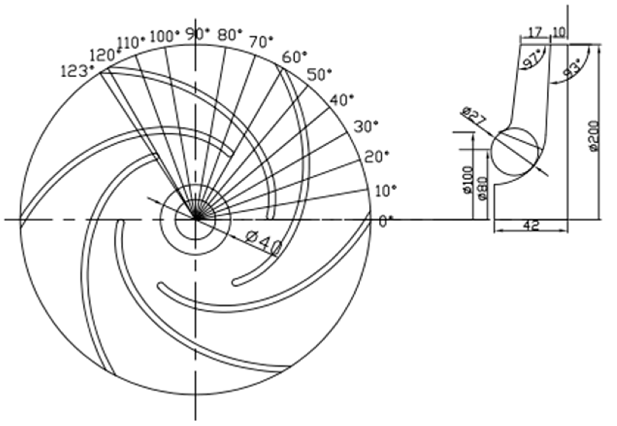
2. Geometry and Parameters

The investigated pump is a plastic centrifugal pump with a semi-open impeller. The basic parameters of the plastic pump are as follows: design flow rate is 50 m3/h, head is 10 m, rotational speed is 1450 rpm,and specific speed is 110.9. The main parameters of the impeller are listed in Table 1. A 2D sketch of an impeller is shown in Figure 1. The original impeller contains six cylindrical constant thickness blades, with a blade thickness of 4 mm. The impeller is whole made of plastic and has a semi open structure. The internal flow and performance of the pump with different blade thickness are studied.

3. Numerical Methods

3.1. Governing Equations

In the simulation, the fluid is assumed to be incompressible and homogeneous. The Navier–Stokes equation based on the Newtonian fluid are as follows [26]:
ρ t + x i ( ρ u i ) = 0
( ρ u i ) t + ( ρ u i u j ) x j = p x i + x j ( μ u i x j ) + τ i j x j
where u is the velocity, p is the pressure, ρ is the mixture density, μ is the viscosity, and τ i j = ρ u i u j ¯ is the Reynolds stress.
Considering the rotating flow inside the pump, the RNG k-ε model was chosen to enclose the equations. The RNG k-ε model can be described as [27]:
( ρ k ) t + ( ρ k u i ) x i = x j [ ( μ + μ t σ k ) k x j ] + G k + ρ ε
( ρ ε ) t + ( ρ ε u i ) x i = x j [ ( μ + μ t σ k ) k x j ] + C 1 ε k G k C 2 ρ ε 2 k
where k denotes the turbulent energy, ε is the turbulent dissipation rate, and the model constants are chosen from [27].

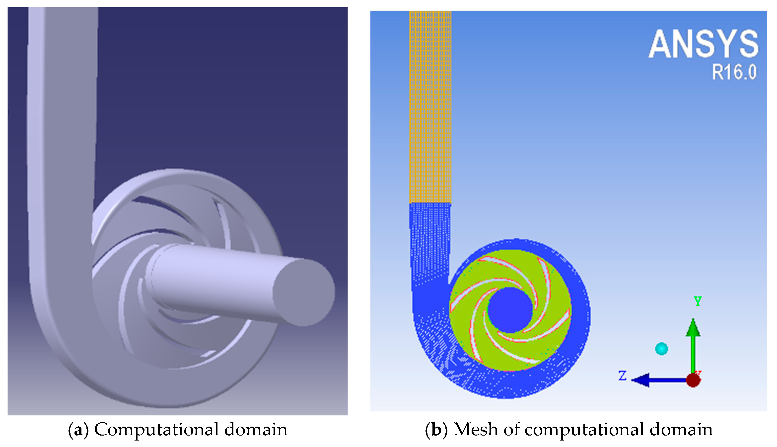
3.2. Numerical Setup and Mesh Generation

According to the structural parameters of the pump, the three-dimensional model of the computation domain was established. In order to keep the inlet and outlet flow stable, the inlet and outlet pipe were extended [28]. The whole computational domain was divided into four parts. The inlet pipe section, impeller, volute, and outlet pipe section are shown in Figure 2. The computational domain was meshed by ICEM-CFD software. All computational domains adopted hexahedral structured grids. The grid independence verification results are shown in Table 2. When the number of grid cells of the computational domain is greater than 750,000, the pump head deviation between the two schemes is less than 0.3% [29]. Therefore, the total number of grid elements adopted for calculation is 895,874, and the grid elements number and mesh details in each computational domain are shown in Table 3.
The boundary condition at the inlet was set as total pressure with 1 atm, and turbulence intensity was 5%. The outlet specified the mass flow rate with 13.89 kg/s. The impeller domain was specified as a rotating domain, whereas the other domains were set as stationary. Moreover, all physical surfaces were set as no-slip wall.

4. Test Setup

The performance experiments of the plastic centrifugal pump were carried out on the closed-loop pump test rig, which was composed of a water tank, pipelines, valves, sensors, and control cabinet, as shown in Figure 3. The pump volute adopted the existing transparent plastic volute in the laboratory, and different impellers were replaced for the test. Moreover, the test medium was water.
The instruments of the test rig and the uncertainty value for each instrument are described at Table 4. The flow rate was adjusted by the outlet valve and measured by an electromagnetic flowmeter, and the measurement accuracy was ±0.5%. The pump head was calculated by measuring the inlet and outlet pressure of the pump. The ranges of pressure transducers were –0.1 MPa to 0.1 MPa at inlet and 0 MPa to 1.6 MPa at outlet, the measurement accuracy was ±0.5%, and the rotational speed of the pump was measured by a photoelectric tachometer with an error of ±0.1%.

5. Results and Discussions

The blade thickness of the metal pump is generally 2~4 mm, and the value of the large pump is even larger [3]. When designing plastic pumps, to ensure the strength of the blades meets the requirements, the blade thickness is generally increased. However, there is no mature method for the design of blade thickness of plastic pumps. The designers usually appropriately increase the blade thickness based on the metal pump according to their experience.
In order to analyze the effects of blade thickness on plastic pump performance, two kinds of blade profiles were investigated: the constant thickness blade (CTB) and the variable thickness blade (VTB), and the other geometric parameters of the impeller were invariable. The thickness of the VTB increased linearly from leading edge to trailing edge, while that of the CTB was constant from leading edge to trailing edge. All the impeller models with different blade thicknesses were simulated, and the flow information and pump performance of different models were obtained.

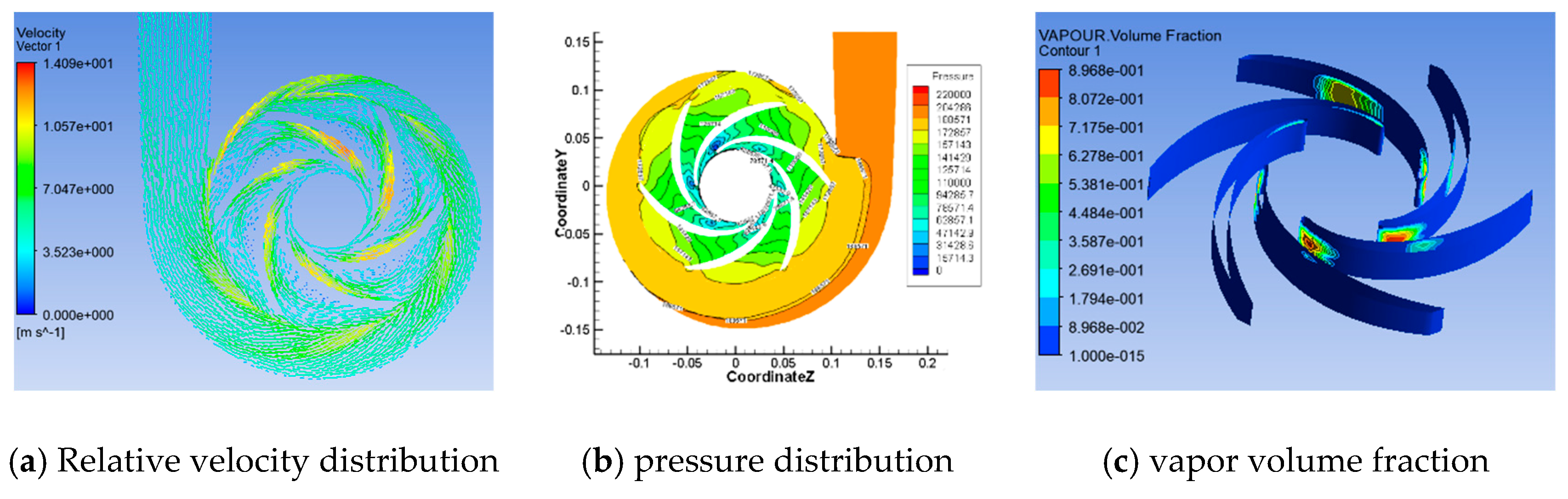
5.1. Flow Field Analysis of CTB

In this study, six impellers with the CTB were established, with blade thickness ranging from 3 mm to 10 mm. The impeller model is named corresponding to the blade thickness; for example, CTB 4 represents CTB with a thickness of 4 mm. The flow information of the impeller with different blade thickness are discussed as follows.

5.1.1. Discussion of the CTB’s Pressure Distribution

The pressure distribution of CTB with different blade thickness is illustrated in Figure 4. For all the six impeller models, the low-pressure zone appears near the impeller inlet, the blade inlet has negative pressure, and the maximum pressure in the pump appears at the volute outlet. The pressure on the pressure surface of blade is greater than that on the suction surface. These results are consistent with Hao’s conclusion [14].
Comparing the pressure distribution of blades with different thicknesses, it is found that the static pressure at the volute outlet of 3 mm, 4 mm, 5 mm, 6 mm, 8 mm, and 10 mm is 207199 Pa, 205822 Pa, 203270 Pa, 204821 Pa, 186152 Pa, and 161190 Pa, respectively. It is observed that when the blade thickness is less than 6 mm, the pressure in the pump does not decrease significantly with the increase in blade thickness. When the blade thickness exceeds 6 mm, with the increase in blade thickness, the pressure in blade channel and volute decreases rapidly, and the negative pressure region at blade inlet also increases significantly.

5.1.2. Discussion of the CTB’s Velocity Distribution

Figure 5 shows the velocity distribution of CTB: the maximum relative velocity of 3 mm, 4 mm, 5 mm, 6 mm, 8 mm, and 10 mm is 13.59 m/s, 13.77 m/s, 15.52 m/s, 16.75 m/s, 17.08 m/s, and 22.3 m/s, respectively. According to Figure 5, the maximum relative velocity in the pump appears in the middle of the blade suction surface. When the blade thickness is less than 6 mm, the relative velocity distribution in the pump cavity is relatively smooth. When the blade thickness exceeds 6 mm, the relative velocity in the blade channel increases rapidly due to the reduction in the blade channel width. Excessive local speed leads to increased flow loss and decreased pump efficiency. In addition, when the blade thickness is less than 5 mm, there are apparent axial vortices in the outlet areas of the blade channel, and the static pressure contour in the channel is also in disorder. This phenomenon gradually disappears when the thickness exceeds 6 mm.

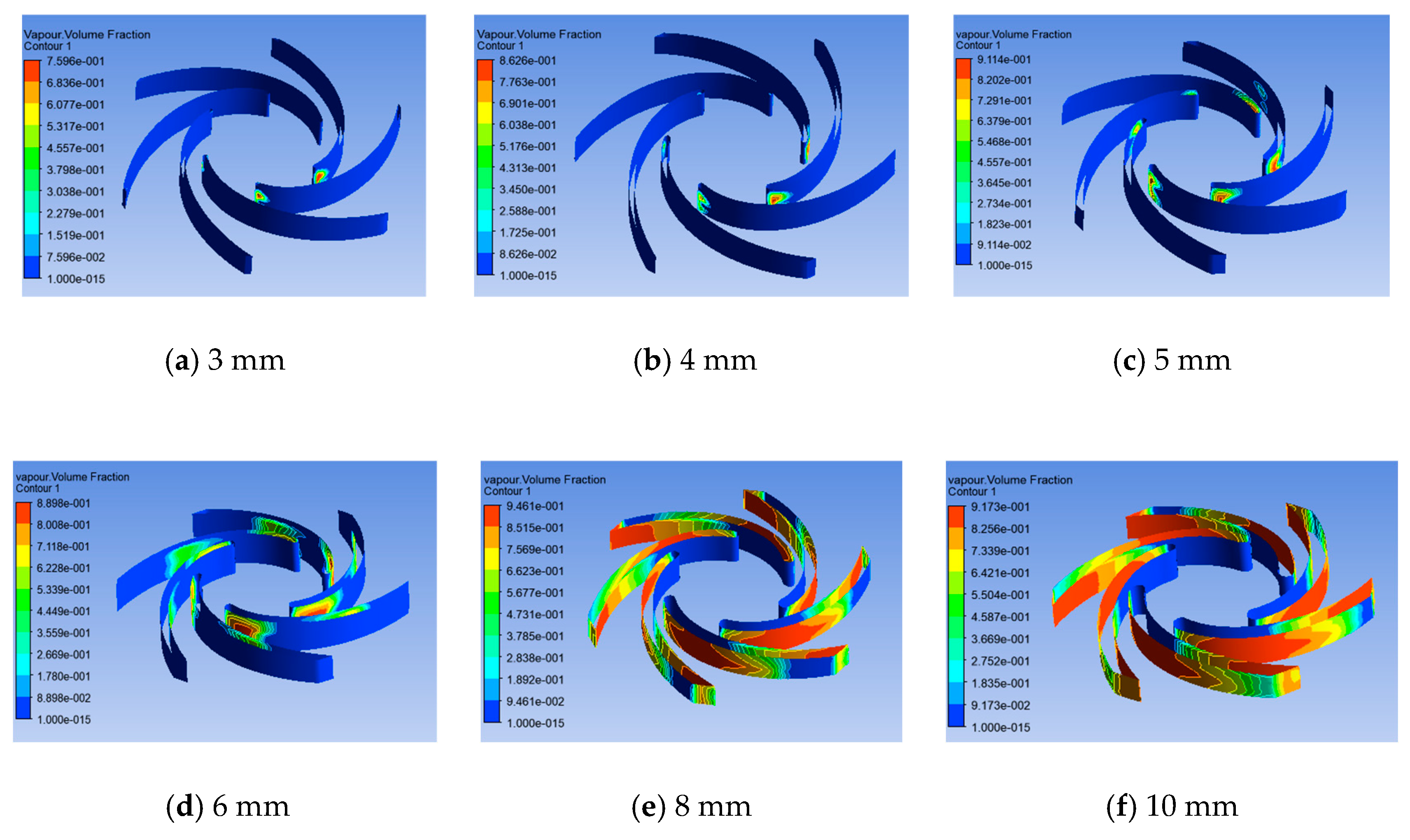
5.1.3. Discussion of the CTB’s Vapor Volume Fraction

In the simulation, the cavitation performance of the pump is studied by reducing the pump inlet pressure. The vapor volume fraction on the blade surface is obtained to compare the cavitation performance of CTB with different thicknesses. Figure 6 demonstrates the vapor volume fraction of CTB when the net positive suction head (NPSH) is 4.8 m. When the blade thickness is less than 5 mm, only a tiny amount of vapor exists at the blade leading edge, while the vapor volume fraction in other areas of the blade is 0. When the blade thickness exceeds 6 mm, the negative pressure zone in the blade channel increases, the vapor gradually diffuses to the trailing edge, and the vapor volume fraction increases with the increase in blade thickness. Therefore, the blade thickness shall be taken as small as possible to improve the anti-cavitation performance of the pump.

5.1.4. Effects of CTB on Pump Performance

The pump performance under rated flow rate of CTB with different blade thickness is demonstrated in Figure 7. The pump efficiency and head change slightly at rated flow when impeller blade thickness changes from 3 mm to 6 mm. If blade thickness exceeds 6 mm, with the increase in blade thickness, the pump efficiency and head decrease rapidly. When the blade thickness is 4 mm, the pump head is 10.79 m, while only 6.24 m of 10 mm with 42.2% decreased. Moreover, when the blade thickness is 4 mm, the pump efficiency is 76.47%. when the blade thickness is 10 mm, the efficiency drops to 46.5%. The blade thickness discussed in other literatures [14,20,21] are less than 6mm, and they did not find that the pump head and efficiency will decrease so obviously with the increase in blade thickness. This result indicates that the thickness should be limited within a reasonable range.

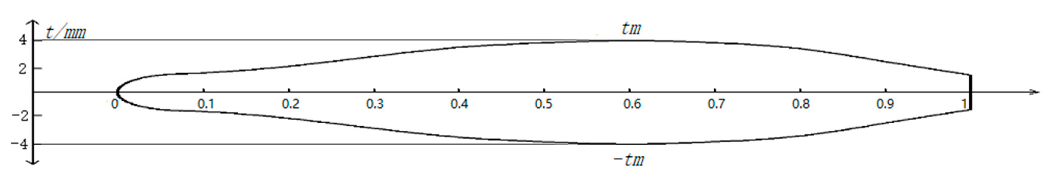
5.2. Discussion of the Minimum Blade Thickness

According to the above analysis, the thin blade is used to improve the performance of the pump. However, due to the particularity of the plastic pump, the blade may break due to insufficient strength during the operation, resulting in pump’s working failure. Therefore, it is necessary to analyze the minimum blade thickness required to ensure the blade’s strength. Finite element analysis is considered an effective strength calculation method [30]. In this study, ANSYS Workbench was used for impeller strength analysis to make sure the blade can meet the strength requirements during the rotation of the impeller.
The finite element analysis of the CTB 3, CTB 4, and CTB 5 were investigated. The strain and stress distributions of impellers with different blade thicknesses under design conditions are shown in Figure 8 and Figure 9.
From the blade strain distribution in Figure 8, it can be observed that the blade strain increases with the decrease in blade thickness. The yield limit of the materials for the investigated plastic pump is about 20 MPa. According to Figure 9, the maximum stress on CTB 3 is exceeded the bearing limit of impeller material. The maximum stresses of CTB 4 and CTB 5 are 13 MPa and 10 MPa, respectively, meeting the strength requirements. Therefore, the minimum blade thickness of the impeller can be 4 mm.

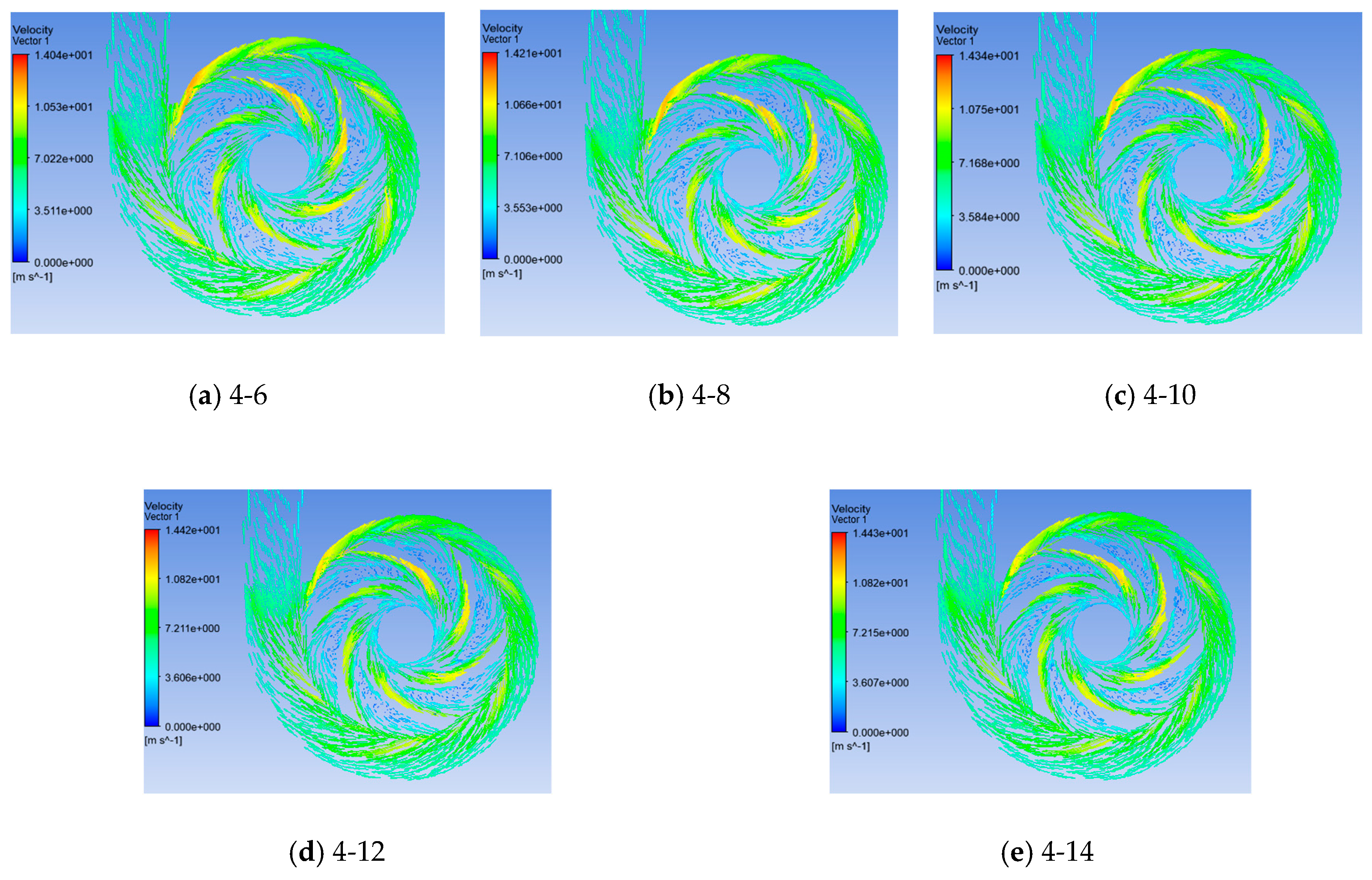
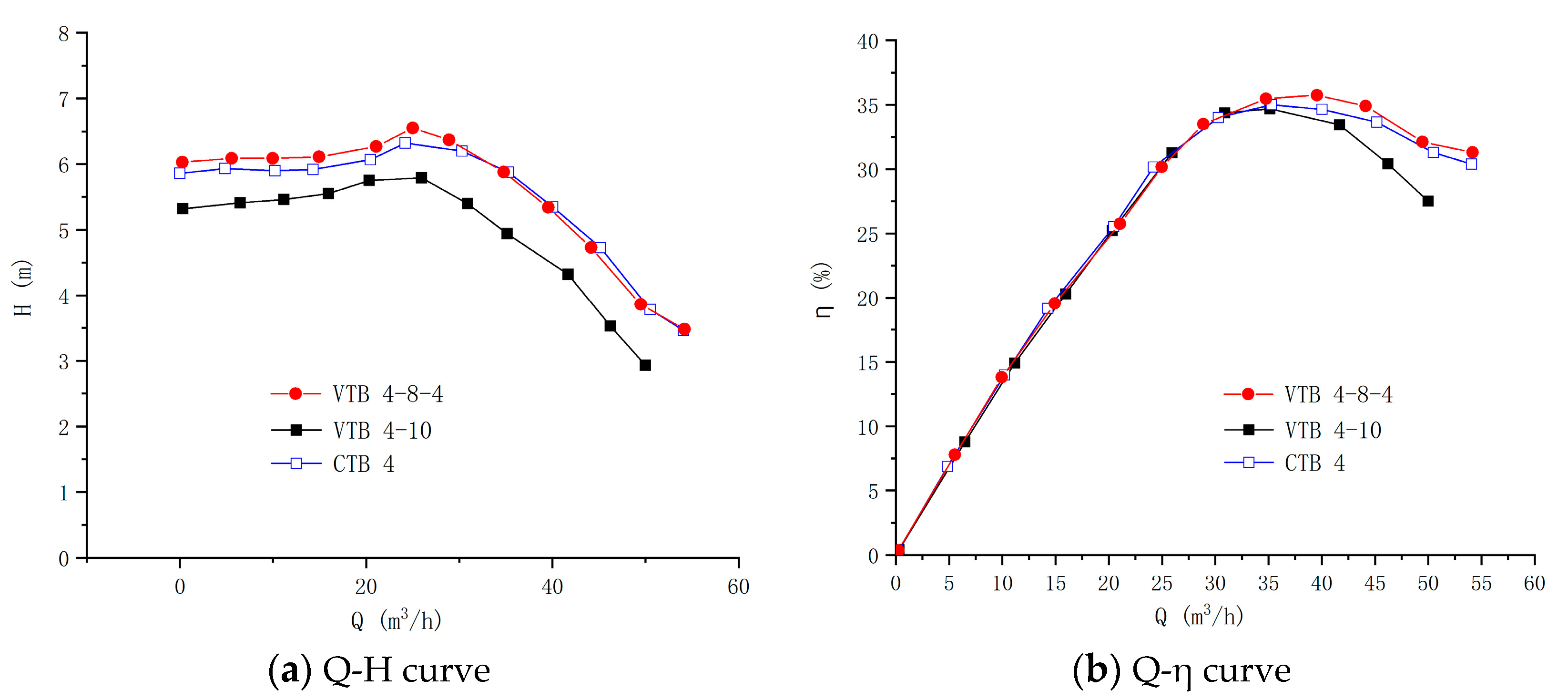
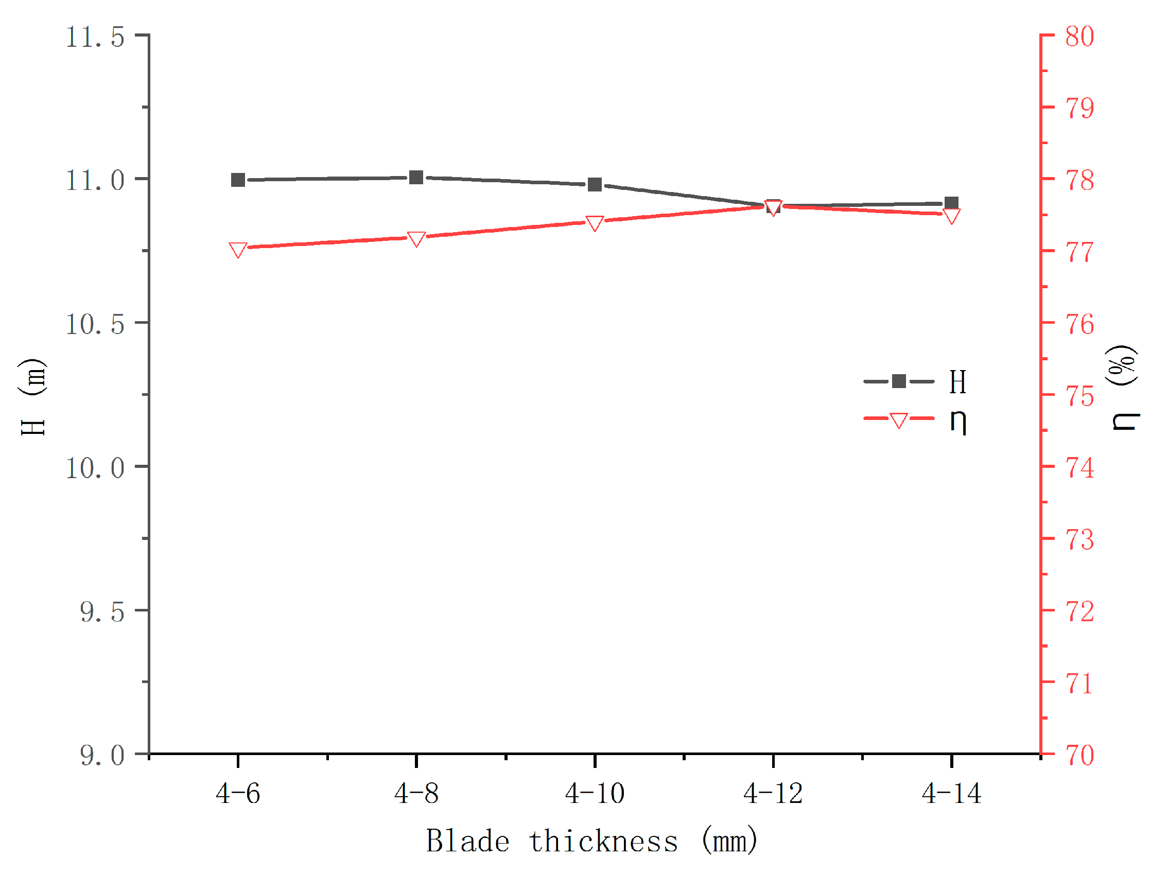
5.3. Effects of VTB on Pump Performance

A centrifugal pump impeller often adopts VTB [15] for improving the abrasion resistance and service life of the impeller [23,24]. Five kinds of VTB impellers were simulated to analyze the effects of blade thickness on the performance of the plastic pump. The thickness at the leading edge of all VTB impeller models was 4 mm to meet the requirement of strength, while the thickness at the trailing edge variated from 6 mm to 14 mm. The VTB impeller design schemes are shown in Table 5.
Figure 10 shows the pressure distribution of the pump with the VTB. It can be found that the pressure at the outlet of different VTB impeller is approximately the same. With the increase in the trailing edge thickness, the pressure difference between the inlet and the outlet of the impeller gradually increases, and the low-pressure zone at the inlet of the impeller becomes larger. Compared with CTB, the pressure contour gradually tends to circular distribution with the increase in trailing edge thickness.
Figure 11 illustrates the velocity distribution of the pump with VTB. As shown in Figure 11, with the increase in trailing edge thickness, the axial vortex in the blade channel gradually decreases. The hydraulic loss caused by flow separation will also reduce. In addition, the velocity at the impeller outlet increases gradually with the increase in trailing edge thickness, and the flow loss here will also increase. The hydraulic loss of the impeller under low flow rate is smaller than that under large flow rate. Therefore, the best efficiency point of the pump will shift to the direction of low flow rate [18,23]. In addition, the cavitation performance of centrifugal pumps mainly depends on the leading edge [3]. The leading edge thickness of the VTB discussed in this study was 4 mm, and its cavitation performance was similar to CTB 4.
The pump performance of the VTB is shown in Figure 12. With the increase in trailing edge thickness, the pump performance changes are not obvious. When the trailing edge thickness increases from 6 mm to 14 mm, the pump head decreases by only 0.1 m, and the pump efficiency increases by 0.4% with the increase in trailing edge thickness.

5.4. Optimization of the Blade Profile

According to Figure 5, for CTB, when the blade thickness less than 6 mm, there are axial vortexes that exist in the blade channel, which lead to increase in hydraulic loss. In addition, as shown in Figure 11, the flow field in the blade channel becomes smoother with the trailing edge thickness increase for VTB. However, with the increase in the trailing edge thickness, the jet wake phenomenon at the impeller outlet will be more pronounced, resulting in a decrease in pump efficiency [3]. According to the literature results, offset the maximum thickness of the VTB toward the leading edge of the blade is conducive to reducing hydro-induced vibration [22] and enhancing the performance of the pump [20]. These conclusions make it possible to improve pump performance by optimizing blade thickness distribution. So, inspired by these results and based on the previous work, a new VTB with the maximum thickness at the middle of the blade was proposed to reduce the hydraulic loss and enhance pump efficiency. The new blade profile is shown in Figure 13.
The new plastic pump blade profile was designed by referring to the airfoil structure, and the blade was designed to be streamlined, with thin leading edge and trailing edge and thick middle. To reduce the jet wake and strengthen the constraint on the fluid in the blade flow channel, the maximum thickness of the new VTB was moved forward from the trailing edge to the middle of the blade so as to improve the flow field in the pump and improve the pump performance. In order to accurately design the blade profile, the blade profile was assumed as a quartic polynomial of the relative chord length k, as shown in Equation (5). Then, the boundary conditions were given according to the structural characteristics of the blade, and the polynomial coefficients were solved to obtain the profile equation of the blade.
t = ± 1 2 t m [ a k + b k + c k 2 + d k 3 + e k 4 ] + f
where t is the blade thickness, tm is the maximum blade thickness, k is the relative chord length (0 ≤ k ≤ 1), and the rest are coefficients. The first derivative of the thickness t with respect to the relative chord length k is as follows:
t k = t m 2 [ a 2 k + b + 2 c k + 3 d k 2 + 4 e k 3 ]
According to the conclusions of Yang et al. [20], the hydraulic efficiency of the pump is the highest when the thickest blade position is located at 33% of the chord length. However, Yang et al. did not consider the influence of leading edge thickness on the cavitation performance of the pump. In the present study, in order to comprehensively optimize the pump efficiency and cavitation performance, the maximum blade thickness is located at 60% of the chord length. The thickness of leading edge and trailing edge is set at a minimum thickness of 4 mm to meet the strength requirements of the impeller, and the maximum blade thickness is specified as 8 mm. In addition, the leading edge of the blade is designed as an ellipse to improve the cavitation performance of the pump. Therefore, it can be obtained the boundary conditions of the blade profile, as shown in Equation (7). Then, the boundary conditions are brought into Equation (5) and Equation (6) to obtain Equation (8).
{ k = 1 , t = 4 k = 0.6 , t = 8 k = 0.04 , t = 4 k = 0.04 , t k = 0.0524 k = 0.6 , t k = 0
{ t m 2 [ a 0.04 + 0.04 b + c ( 0.04 ) 2 + d ( 0.04 ) 3 + e ( 0.04 ) 4 ] + 2 = 2 t m 2 [ a 0.6 + 0.6 b + c ( 0.6 ) 2 + d ( 0.6 ) 3 + e ( 0.6 ) 4 ] + 2 = 4 t m 2 [ a + b + c + d + e ] + 2 = 2 t m 2 [ a 2 0.04 + b + 0.04 c + 3 × ( 0.04 ) 2 d + 4 × ( 0.04 ) 3 e ] = 0.0524 t m 2 [ a 2 0.6 + b + 2 × 0.6 c + 3 × ( 0.6 ) 2 d + 4 × ( 0.6 ) 3 e ] = 0
According to Equation (8), the blade profile can be obtained by specifying the maximum thickness of the blade. Comparing the simulation results of different maximum blade thicknesses, it is found that the pump performance is the best when the maximum thickness of the blade is 8 mm, and the corresponding coefficients a, b, c, e, and f are 0.088, –0.73, 7.7, –11.428, and 4.371, respectively. Then, the blade profile equation of the plastic centrifugal pump is:
t = ± 1 2 t m [ 0.088 k 0.73 k + 7.67 k 2 11.428 k 3 + 4.371 k 4 ] + 2
The impeller with the new profile was defined as VTB 4–8–4, which was simulated to obtain the flow field information in the pump, as shown in Figure 14. The axial vortex in the blade channel disappeared, and the flow separation of fluid in the impeller is weakened. The pressure distribution in the blade channel is reasonable. The vapor volume fraction on the blade surface increases slightly compared with CTB 4. In addition, the pump head and efficiency of VTB 4–8–4 is 10.76 m and 78.12%, respectively. Compared with CTB 4, the pump efficiency increased by 1.65%.

5.5. Test

According to the previous simulation analysis results, three impeller models of CTB 4, VTB 4-6 and VTB 4-8-4 were manufactured by the 3D printing method, as shown in Figure 15. Performance tests of the three models were carried out, respectively, and the test results are shown in Figure 16. Under the design flow rate, the performance of the VTB 4-8-4 model is the best, and VTB 4-10 impeller is the worst. The efficiency of the VTB 4-8-4 model is 32.11%, 1.67% higher than that of the VTB 4 model and 4.6% higher than that of VTB 4-10. The difference between the three impeller models is close to the simulation results.
Comparing the test and simulation results of the pump, it is clear that there is a significant gap in the values, and the test values are significantly lower than the simulation results. The reasons of the low-test head and efficiency of the pump mainly came from two aspects. The first was the excessive clearance between the impeller and the volute. An existing pump case in the laboratory was used for the test, and the test models were semi-open impeller. The inlet diameter and width of the volute were too large, resulting in excessive clearance between the impeller and the volute. When the pump was tested, there was backflow in the pump cavity, and then the pump efficiency and head decreased. The second was that there was a small amount of leakage at the outlet flange during the test. The pump volute used in the test was a plastic pump volute. When assembling with the metal flange at the outlet, the preload of bolts cannot be too large. There was a small amount of leakage at the outlet flange due to insufficient sealing pressure. However, the above two factors had the same impact on the three test impellers. Therefore, it was feasible to compare the performance of different impellers with the test results.

6. Conclusions

In the present work, the influence of blade thickness of plastic centrifugal pump impeller on pump performance is studied. The flow field and performance difference of plastic centrifugal pump with different blade thickness (CTB and VTB) are analyzed in detail. The minimum blade thickness needed to meet the strength requirements of the impeller is discussed. A new variable thickness blade is proposed to improve the performance of the pump. The following conclusions can be drawn from the analysis of the results:
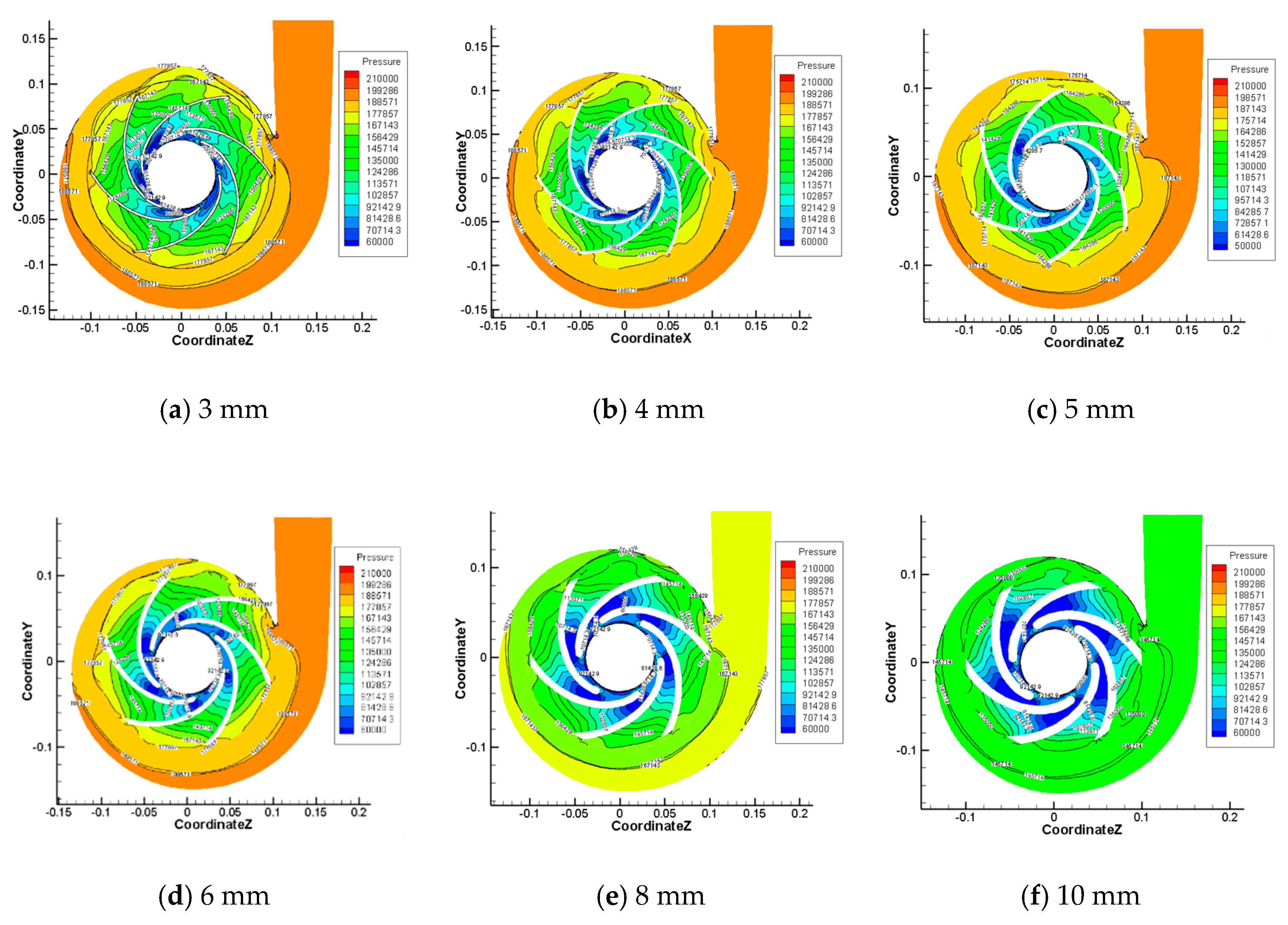
  • The blade thickness had a significant impact on the performance of the plastic pump. For CTB, the pump performance changed a little when the thickness was 3 mm to 5 mm. When the blade thickness exceeded 6mm, the performance parameters of the pump decreased rapidly. The head and efficiency CTB 10 decreased by 42.2% and 30%, respectively, compared with CTB 4.
  • Based on the finite element analysis, the minimum blade thickness of the researched pump should be 4 mm in order to meet the requirement of blade strength.
  • The head and efficiency of the pump did not change significantly, when the trailing edge thickness of the VTB changed within a certain range (6 mm to 14 mm).
  • The thickness distribution of VTB was optimized, and the maximum thickness was changed from the trailing edge to 60% chord length. The efficiency of the optimized impeller VTB 4-8-4 was 1.67% higher than that of CTB 4.
The current work on VTB is not enough. In future research, it is necessary to explore further effects of the blade thickness distribution on the pump performance. Moreover, the vapor volume fraction around the blades is used to compare the cavitation performance of the pump in this work. Further research can directly compare the NPSHa of the pump with different blade thickness. In addition, in future research, it is essential to improve the test conditions and improve the test accuracy.

Author Contributions

Conceptualization, Z.X.; Methodology, Z.X.; Software, M.L.; Validation, M.L. Formal Analysis, L.T.; Investigation, J.W.; Resources, L.T.; Data Curation, Z.X.; Writing—Original Draft Preparation, Z.X.; Writing—Review and Editing, Z.X.; Supervision, J.W.; Project Administration, F.K.; Funding Acquisition, N.Q. All authors have read and agreed to the published version of the manuscript.

Funding

This work is supported by National Natural Science Foundation of China (No. 51806082) and Jiangsu Province’s Key Research and Development Program of China (No. BE2018085), the authors express their gratitude for their support.

Data Availability Statement

Data is contained within the article.

Conflicts of Interest

The authors declare no conflict of interest.

References

  1. Li, J.; Tang, L.; Zhang, Y. The Influence of Blade Angle on the Performance of Plastic Centrifugal Pump. Adv. Mater. Sci. Eng. 2020, 6, 1–20. [Google Scholar] [CrossRef]
  2. Tang, L.; Liu, M.; Ma, F. Thermosetting Coupling Analysis and Parameter Optimization of the Plastic Lining Pump Structure. Adv. Mater. Sci. Eng. 2019, 6, 1–15. [Google Scholar] [CrossRef] [Green Version]
  3. Guan, X. Modern Pumps Theory and Design; Astronautic Publishing House: Beijing, China, 2011. [Google Scholar]
  4. Luo, X.; Zhang, Y.; Peng, J.; Xu, H.; Yu, W. Impeller inlet geometry effect on performance improvement for centrifugal pumps. J. Mech. Sci. Technol. 2008, 22, 1971–1976. [Google Scholar] [CrossRef]
  5. Tan, L.; Zhu, B.; Cao, S.; Bing, H.; Wang, Y. Influence of Blade Wrap Angle on Centrifugal Pump Performance by Numerical and Experimental Study. Chin. J. Mech. Eng. 2014, 27, 171–177. [Google Scholar] [CrossRef]
  6. Zhang, H.; Tang, L.; Zhao, Y. Influence of Blade Profiles on Plastic Centrifugal Pump Performance. Adv. Mater. Sci. Eng. 2020, 2020, 6665520. [Google Scholar] [CrossRef]
  7. Suh, J.W.; Kim, J.W.; Choi, Y.S.; Kim, J.H.; Joo, W.G.; Lee, K.Y. Multi-Objective Optimization of the Hydrodynamic Performance of the Second Stage of a Multi-Phase Pump. Energies 2017, 10, 1334. [Google Scholar] [CrossRef] [Green Version]
  8. Wang, W.; Pei, J.; Yuan, S.; Zhang, J.; Yuan, J.; Xu, C. Application of different surrogate models on the optimization of centrifugal pump. J. Mech. Sci. Technol. 2016, 30, 567–574. [Google Scholar] [CrossRef]
  9. Liu, H.; Kai, W.; Yuan, S.; Tan, M.; Liang, D. Multicondition Optimization and Experimental Measurements of a Double-Blade Centrifugal Pump Impeller. J. Fluids Eng. 2013, 135, 111031. [Google Scholar] [CrossRef] [Green Version]
  10. Kumar, P.M.; Seo, J.; Seok, W.; Rhee, S.H.; Samad, A. Multi-fidelity optimization of blade thickness parameters for a horizontal axis tidal stream turbine. Renew. Energy 2019, 135, 277–287. [Google Scholar] [CrossRef]
  11. Sjka, B.; Ysca, B.; Yong, C.C.; Jwc, C.; Jhka, B. Effect of blade thickness on the hydraulic performance of a Francis hydro turbine model. Renew. Energy 2019, 134, 807–817. [Google Scholar]
  12. Yang, S.S.; Wang, C.; Chen, K.; Yuan, X. Research on Blade Thickness Influencing Pump as Turbine. Adv. Mech. Eng. 2014, 6, 1–8. [Google Scholar] [CrossRef]
  13. Qiu, N.; Zhou, W.; Che, B.; Wu, D.; Zhu, H. Effects of microvortex generators on cavitation erosion by changing periodic shedding into new structures. Phys. Fluids. 2020, 32, 104108. [Google Scholar] [CrossRef]
  14. Chang, H.; Li, W.; Shi, W.; Liu, J. Effect of blade profile with different thickness distribution on the pressure characteristics of novel self-priming pump. J. Braz. Soc. Mech. Sci. Eng. 2018, 40, 518. [Google Scholar] [CrossRef]
  15. Kim, Y.I.; Kim, S.; Yang, H.; Lee, K.Y.; Choi, Y.S. Analysis of internal flow and cavitation characteristics for a mixed-flow pump with various blade thickness effects. J. Mech. Sci. Technol. 2019, 33, 3333–3344. [Google Scholar] [CrossRef]
  16. Nazeryan, M.; Lakzian, E. Detailed entropy generation analysis of a Wells turbine using the variation of the blade thickness. Energy 2017, 143, 385–405. [Google Scholar] [CrossRef]
  17. Ma, C.; Li, W.; Wang, H.; Chen, H. Influence of Thickness Distribution of Diffuser Vane on Performance of Centrifugal Compressor. J. Eng. Therm. Energy Power 2018, 33, 52–57. [Google Scholar]
  18. Wang, C.; Shi, W.; Zhou, L.; Lu, W. Effect Analysis of Geometric Parameters on Stainless Steel Stamping Multistage Pump by Experimental Test and Numerical Calculation. Adv. Mech. Eng. 2015, 5, 1–8. [Google Scholar] [CrossRef]
  19. Ha, Y.; Hou, L. Effects of blade thickness on performance of axial flow pump and analysis of internal flow field. Trans. Chin. Soc. Agric. Eng. 2012, 28, 75–81. [Google Scholar]
  20. Yang, M.G.; Sheng, L.U.; Gao, B.; Wang, D.; Wang, J. Influence of Blade Thickness on Energy Performance of Mixed Flow Nuclear Main Pump. Fluid Mach. 2015, 43, 28–32. [Google Scholar]
  21. Zhao, W.; Liu, M.; Liu, Y.; Sheng, J.; Song, Q. Effects of blade thickness on performance of low-specific-speed centrifugal pump. J. Drain. Irrig. Mach. Eng. 2015, 33, 1033–1037. [Google Scholar]
  22. Qian, B.; Wu, P.; Huang, B.; Zhang, K.; Wu, D. Optimization of a Centrifugal Impeller on Blade Thickness Distribution to Reduce Hydro-induced Vibration. J. Fluids Eng. 2019, 142, 021202. [Google Scholar] [CrossRef]
  23. Tao, Y.; Yuan, S.; Liu, J.; Zhang, F.; Tao, J. The influence of the blade thickness on the pressure pulsations in a ceramic centrifugal slurry pump with annular volute. Proc. Inst. Mech. Eng. Part A J. Power Energy 2017, 231, 415–431. [Google Scholar] [CrossRef]
  24. Tao, Y.; Bai, Y.; Wu, Y. Influence of Blade Thickness on Solid–Liquid Two-Phase Flow and Impeller Wear in a Ceramic Centrifugal Slurry Pump. Processes 2021, 9, 1259. [Google Scholar] [CrossRef]
  25. Tao, Y.; Yuan, S.; Liu, J.; Zhang, F.; Tao, J. Influence of Blade Thickness on Transient Flow Characteristics of Centrifugal Slurry Pump with Semi-open Impeller. Chin. J. Mech. Eng. 2016, 29, 1209–1217. [Google Scholar] [CrossRef]
  26. Xu, Z.; Kong, F.; Zhang, H.; Zhang, K.; Wang, J.; Qiu, N. Research on Visualization of Inducer Cavitation of High-Speed Centrifugal Pump in Low Flow Conditions. J. Mar. Sci. Eng. 2021, 9, 1240. [Google Scholar] [CrossRef]
  27. Versteeg, H.K.; Malalasekera, W. An Introduction to Computational Fluid Dynamics; Addison-Wesley-Longman: Boston, MA, USA, 1995. [Google Scholar]
  28. Zhang, D.; Shi, W.; Pan, D.; Dubuisson, M. Numerical and experimental investigation of tip leakage vortex cavitation patterns and mechanisms in an axial flow pump. J. Fluids Eng. 2015, 137, 121103. [Google Scholar] [CrossRef]
  29. Al-Obaidi, A.R. Investigation of the influence of various numbers of impeller blades on internal flow field analysis and the pressure pulsation of an axial pump based on transient flow behavior. Heat Transfer. 2020, 49, 2000–2024. [Google Scholar] [CrossRef]
  30. Strait, D.S.; Qian, W.; Dechow, P.C.; Ross, C.F.; Richmond, B.G.; Spencer, M.A. Modeling elastic properties in finite-element analysis: How much precision is needed to produce an accurate model? Anat. Rec. Part A Discov. Mol. Cell. Evol. Biol. 2010, 283A, 275–287. [Google Scholar] [CrossRef]
Figure 1. 2D sketch of the original impeller.
Machines 10 00061 g001
Figure 2. Computational domain model and mesh of pump.
Machines 10 00061 g002
Figure 3. Test rig.
Figure 3. Test rig.
Machines 10 00061 g003
Figure 4. Pressure distribution of CTB.
Machines 10 00061 g004
Figure 5. Velocity distribution of CTB.
Machines 10 00061 g005
Figure 6. Vapor volume fraction on blade surface of CTB (NPSH = 4.8 m).
Machines 10 00061 g006
Figure 7. Pump performance of CTB.
Machines 10 00061 g007
Figure 8. Strain distribution of impeller.
Machines 10 00061 g008
Figure 9. Stress distribution of impeller.
Machines 10 00061 g009
Figure 10. Pressure distribution of VTB.
Machines 10 00061 g010
Figure 11. Velocity distribution of VTB.
Machines 10 00061 g011
Figure 12. Pump performance of VTB.
Machines 10 00061 g012
Figure 13. Blade profile.
Machines 10 00061 g013
Figure 14. Flow field information of VTB 4-8-4.
Machines 10 00061 g014
Figure 15. Test impelle.
Machines 10 00061 g015
Figure 16. Test results of plastic centrifugal pump.
Machines 10 00061 g016
Table 1. Main parameters of the original impeller.
VariablesValue
Inlet diameter (mm)80
Outlet diameter (mm)200
Inlet width (mm)27
Outlet width (mm)17
Inlet angle (°)19
Outlet angle (°)33
Wrap angle (°)123
Number of blades6
Table 2. Results of grid independence.
SchemeNo. of Mesh Cells (×104)Head (m)Deviation of Head (%)
1619.878
27510.422.3
38910.680.2
411410.690.3
514210.66-
Table 3. Mesh details in each domain.
Inlet SectionImpellerVoluteOutlet Section
No. of cells6792249848627816451302
Orthogonality0.77–10.271–10.251–10.758–1
Skewness0.63–10.214–10.236–10.589–1
Aspect ratio0.038–0.9890.015–0.980.015–0.9980.018–1
Min angle52.4818.2219.9450.52
Quality0.7320.3410.2840.742
Table 4. Instruments of the test rig.
InstrumentsUnitAccuracyUncertainty Value
Electromagnetic flowmeterm3/h±0.5%±0.05
Pressure transducer (inlet)MPa±0.5%±0.005
Pressure transducer (outlet)MPa±0.5%±0.0005
Tachometerrpm±0.1%±3
Table 5. VTB impeller design scheme.
SchemeThickness of Leading Edge (mm)Thickness of Trailing Edge (mm)
VTB 4–646
VTB 4–848
VTB 4–10410
VTB 4–12412
VTB 4–14414
Publisher’s Note: MDPI stays neutral with regard to jurisdictional claims in published maps and institutional affiliations.

