Communication

Operating Characteristic Analysis and Verification of Short-Stroke Linear Oscillating Actuators Considering Mechanical Load

1
Department of Electrical Engineering, Chungnam National University, Daejeon 34134, Korea
2
Department of Electrical & Electronics Engineering, Chungnam State University, Cheongyang 33303, Korea
3
Department of Power System Engineering, Chonnam National University, Yeosu 59626, Korea
*
Author to whom correspondence should be addressed.
Machines 2022, 10(1), 48; https://doi.org/10.3390/machines10010048
Submission received: 29 November 2021 / Revised: 3 January 2022 / Accepted: 6 January 2022 / Published: 9 January 2022
(This article belongs to the Special Issue Design and Manufacture of Advanced Machines)

Abstract

:
Linear oscillating machines are electric devices that reciprocate at a specific frequency and at a specific stroke. Because of their linear motion, they are used in special applications, such as refrigerators for home appliances and medical devices. In this paper, the structure and electromagnetic characteristics of these linear oscillating machines are investigated, and the stroke is calculated according to voltage and motion equations. In addition, static and transient behavior analysis is performed, considering mechanical systems such as springs, damping systems, and mover mass. Furthermore, in this study, the magnetic force is analyzed, experiments are conducted according to the input power, and the current magnitude and stroke characteristics are analyzed according to the input frequency. Finally, the study confirmed that the most efficient operation is possible when the electrical resonance frequency matches the resonance frequency of the linear oscillating machines.

1. Introduction

Linear oscillating machines (LOMs) are electric devices that reciprocate at a specific frequency and at a specific stroke. Because of their linear motion, they are used in special applications, such as refrigerators for home appliances, and medical devices. LOMs can be classified according to the movement type as the moving-core-type, moving-coil-type, and moving-magnet-type LOMs. The moving-core-type LOM has the advantage of being able to easily increase the permanent magnet usage and the output; however, the price of such LOMs increases with the increase in magnet usage. The moving-coil-type LOM has the highest output density compared to the other two types, but it is difficult to manufacture. Most LOMs used in practical applications are of the moving-magnet type, in which the mover is light and suitable for high-speed operation; this is the most efficient method of increasing LOM output [1,2,3,4,5]. A novel design of a single-phase short-stroke LOM has been developed for application in refrigeration compressors and other similar equipment because of its advantages such as high transmission efficiency and simple structure [6,7,8,9]. However, the evaluation of the LOM performance is difficult because of its reciprocating linear motion. Additionally, unlike rotating machines, measuring the magnetic force of LOMs can be complicated. Therefore, LOM analysis and performance evaluation are essential not only in terms of finite-element method (FEM) analysis but also experimental verification. Various researchers have conducted experimental studies on the electromagnetic force and output of LOMs [10,11,12]. In the current study, the structural and electromagnetic characteristics of a moving-magnet-type LOM were determined and verified through the analysis and experimental study of magnetic force based on the operating frequency and applied voltage. Because the operation of the LOM is the most efficient at the resonance frequency, the consideration of the operating frequency in the electromagnetic design is essential.
The software used for this study is ANSYS Maxwell 2021 R2. An implicit approach has been utilized, and quadratic type elements were used. All analysis results have a resolution of 100 per electrical cycle.

2. Analysis of LOAs

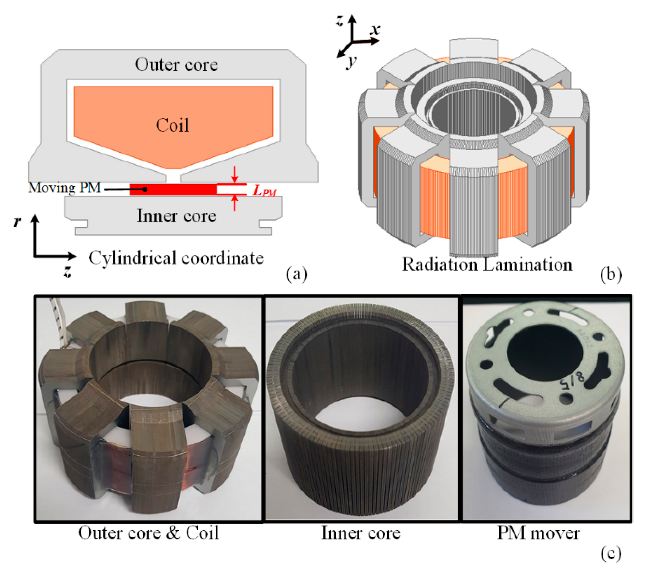
2.1. Topology and Features

Figure 1a illustrates the structure of the LOM, comprising an outer core, a coil, and an inner core, and possesses a structure in which the permanent magnet produces a linear reciprocating motion in the z-axis direction. Figure 1b shows the 3D shape of the LOM. The outer and inner cores are laminated in the radial direction to reduce the eddy current loss, and the outer core is made of several divided cores to increase the space utilization. Figure 1c shows the manufactured components of the LOM.

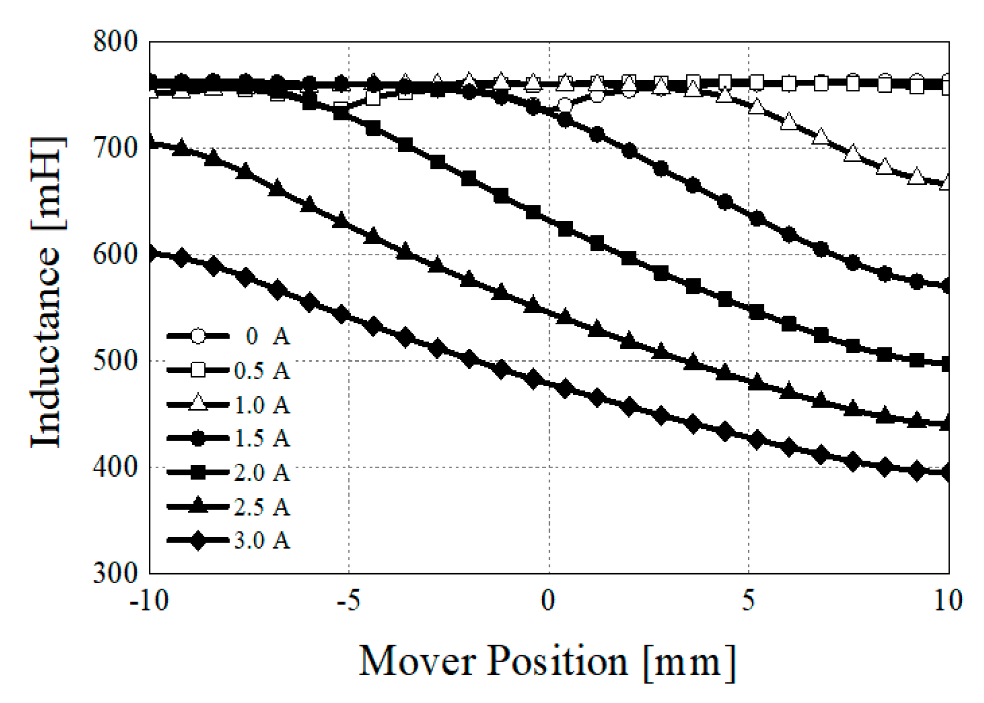
2.2. Electromagnetic Characteristic of LOM

Figure 2 depicts the flux path and flux density of our LOM. The permanent magnet makes a reciprocating motion in the z-axis direction and changes the direction of the main magnetic flux flowing in the outer core, thus generating a back electromotive force (back EMF), which can be calculated as follows:
E = N t u r n d ϕ d t = N t u r n v s d ϕ d z
where Nturn and vs are the coil turns and mover speed, respectively. The LOM should be designed to produce a constant stroke. The maximum magnetic stroke is determined by the length of the permanent magnet. The stroke can be identified from the magnetic force and back EMF as the mover moves at a unit speed (1 m/s). Figure 3 shows that the back EMF and magnetic force vary according to the mover’s position. In addition, the maximum stroke range can be deduced from the maximum and minimum values of the magnetic force, and the value of the back EMF in this region is confirmed to be constant. As the inductance varies with respect to the position of the mover and the magnitude of the current, the instantaneous inductance can be analyzed, as shown in Figure 4.

2.3. Electromagnetic Loss Characteristic of LOM
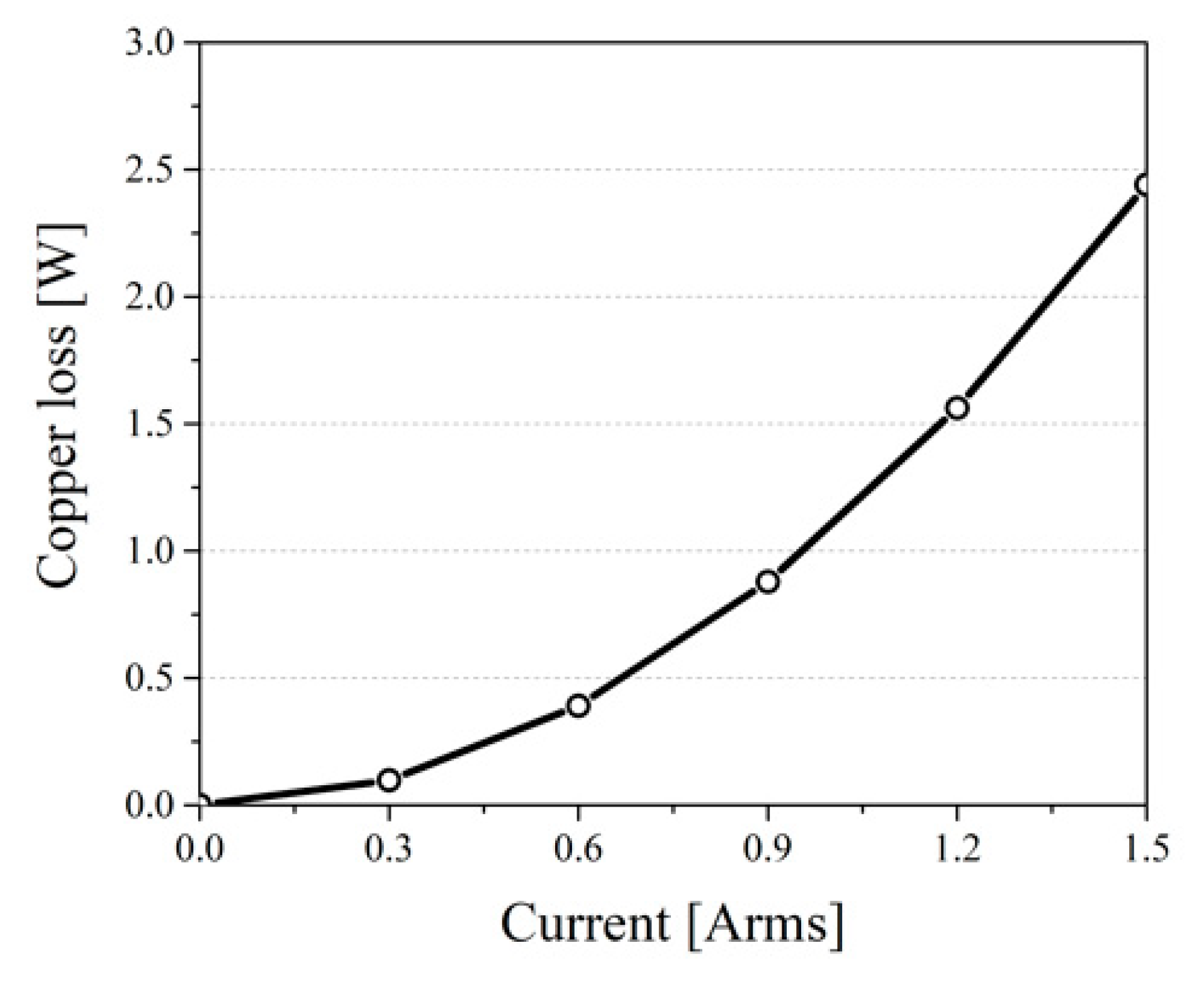
Electromagnetic loss of LOM consists of copper loss, permanent rotor magnet eddy current loss, and core loss. Since it is difficult to consider the mechanical loss in the design stage, it was ignored in this study.

2.3.1. Copper Loss

The copper loss of LOM consists of DC loss and AC loss. When the operating frequency is high, AC loss must be considered in order to consider the skin effect, but only DC loss is considered because the LOM of this study has a low operating frequency of 60 Hz. Since it is single-phase, the DC loss of copper loss is calculated as follows:
P c o p p e r = R p h I r m s 2
where Rph and Irms represent the single-phase winding resistance and rms values of the single-phase current, respectively. Figure 5 shows the copper loss according to the applied current magnitude.

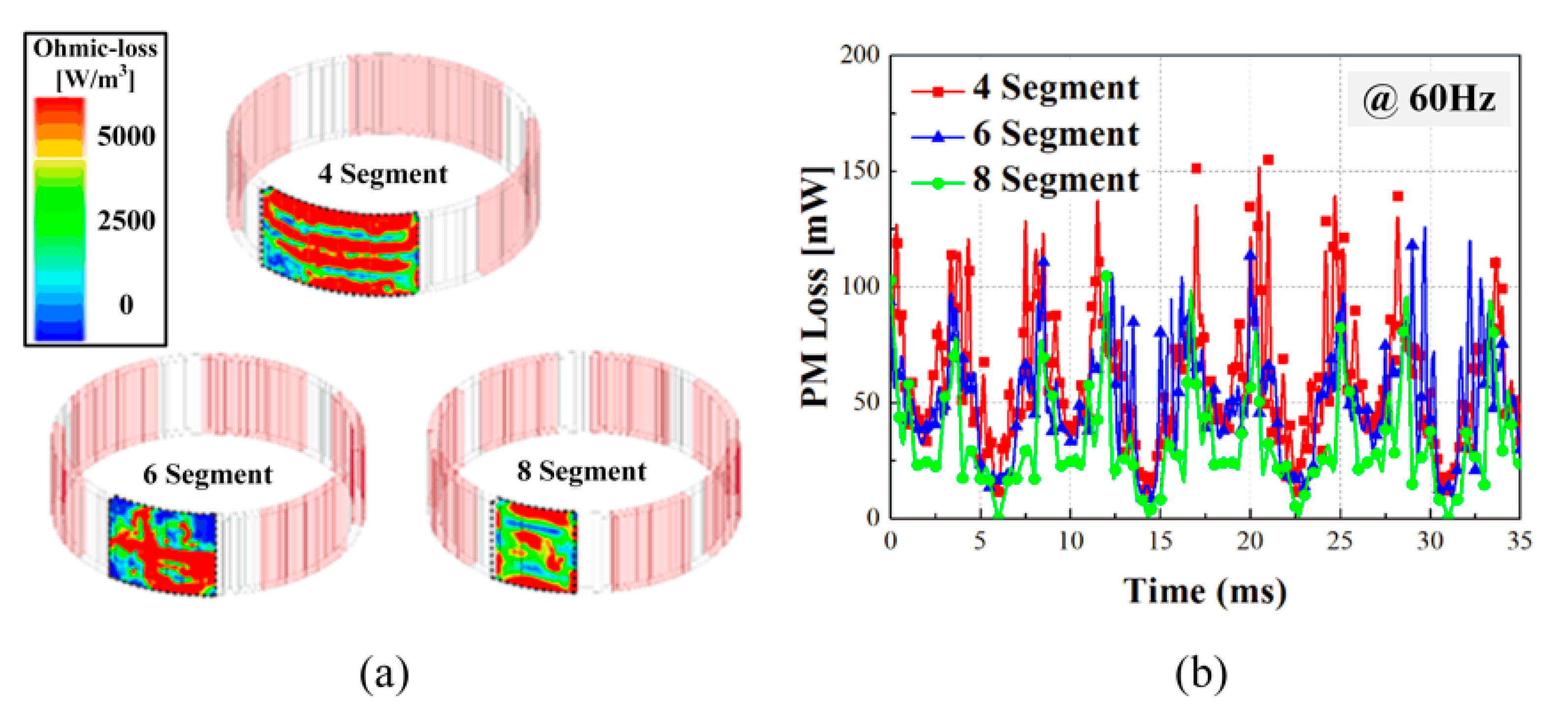
2.3.2. Eddy Current Loss
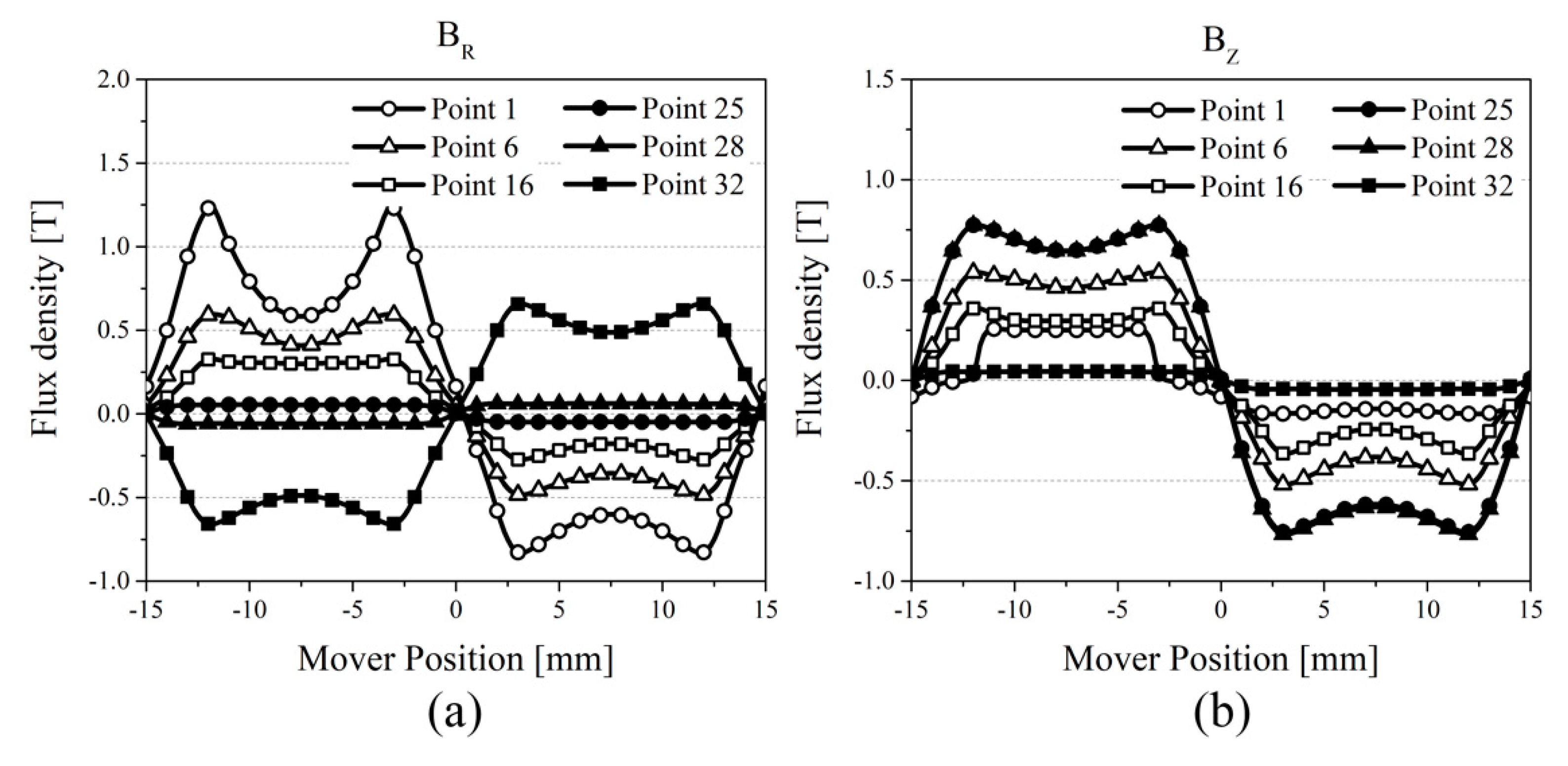
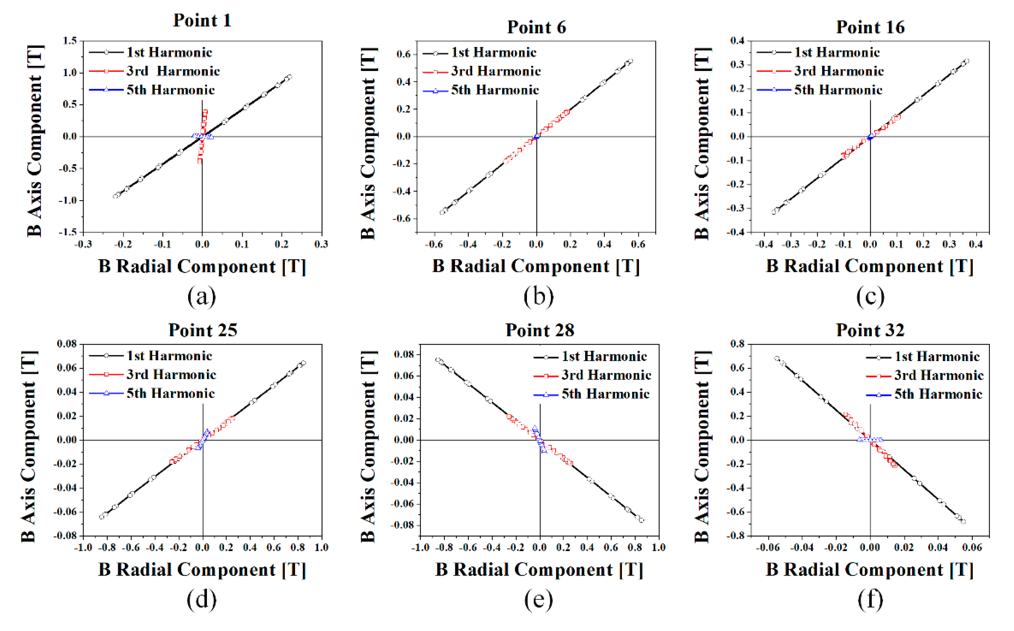
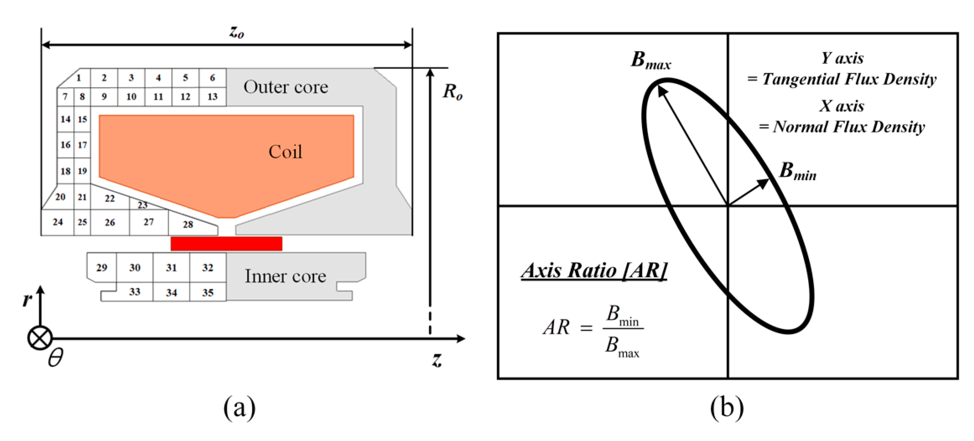
The eddy current loss occurring in the permanent magnet can be calculated as a function of the eddy current density and the permanent magnet volume, as shown in Equation (3) [13]:
P e d d y = n { V m | J e n 2 | σ m d V }
where Peddy, Jen, Vm, and σm represent the total eddy current loss in PM, the nth eddy current density harmonic of PM, the PM volume, and the PM conductivity, respectively. In order to reduce the eddy current in the permanent magnet, the LOM in this paper was designed with several magnet segments.
Figure 6a shows the permanent magnet loss distribution obtained by the three-dimensional finite element analysis method according to the number of permanent magnet segments. Figure 6b shows the eddy current loss analysis result according to the number of magnet segments. As shown, the eddy current loss decreases as the number of segments of the magnet increases. The LOM of this study has an eight-segment PM in consideration of the eddy current loss reduction.

2.3.3. Core Loss

In this study, core loss analysis was performed using the modified Steinmetz equation presented by Bertotti [14]. In particular, the magnetic flux density and magnetic field behavior of each region were analyzed by dividing the stator into regions [15]. Finally, core loss considering the rotating magnetic field and the alternating magnetic field was calculated. The modified Steinmetz equation considering magnetic behavior is as follows:
P c o r e = l = 1 , o d d α l ( k h l f l B l n s t + k e l f l 2 B l 2 + k a l f l 1.5 B l 1.5 ) , { α = 1 , alternating   field α = 2 , rotationg   field }
where kh, ke, and ka represent the hysteresis loss coefficient, the eddy current loss coefficient, and the excessive loss coefficient, respectively. The rotating magnetic field and the alternating magnetic field are distinguished by α.
Figure 7a shows the analysis models of the outer stator and the inner stator for core loss analysis. The outer stator is divided into 28 regions, and the inner stator is divided into 7 analysis regions. Figure 8 shows the magnetic flux density in each area of the stator according to the position of the mover. Figure 7b shows the conceptual diagram of the axial ratio. A rotating magnetic field and an alternating magnetic field are distinguished from the ratio of the maximum and minimum values of each component of the normal magnetic flux density and the tangential magnetic flux density. Figure 8a shows the radial magnetic flux density in regions 1, 6, 16, 25, 28, and 32, and Figure 8b shows the axial magnetic flux density. Figure 9 shows the magnetic field behavior analysis for the first harmonic component, third harmonic component, and fifth harmonic component of the magnetic flux density for each region. It can be seen that the magnetic field in most regions of a linear permanent magnet motor consists of an alternating magnetic field. The results of the core loss analysis considering the harmonics of magnetic flux density and magnetic field behavior are shown in Figure 10. It can be seen that the core loss increases as the magnitude of the current and the operating frequency increases. Table 1 shows the loss and efficiency characteristics of the LOM at rated load.

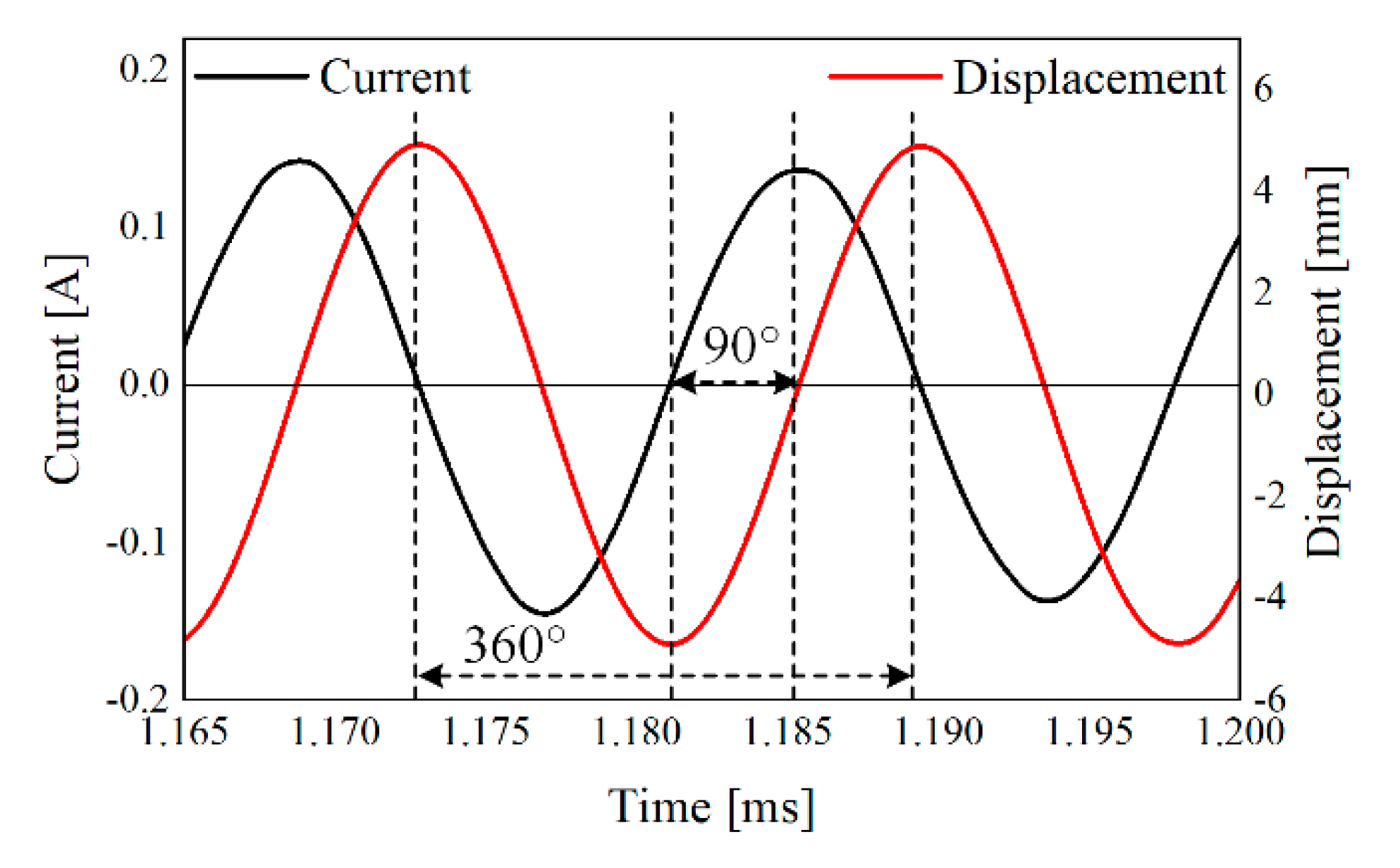
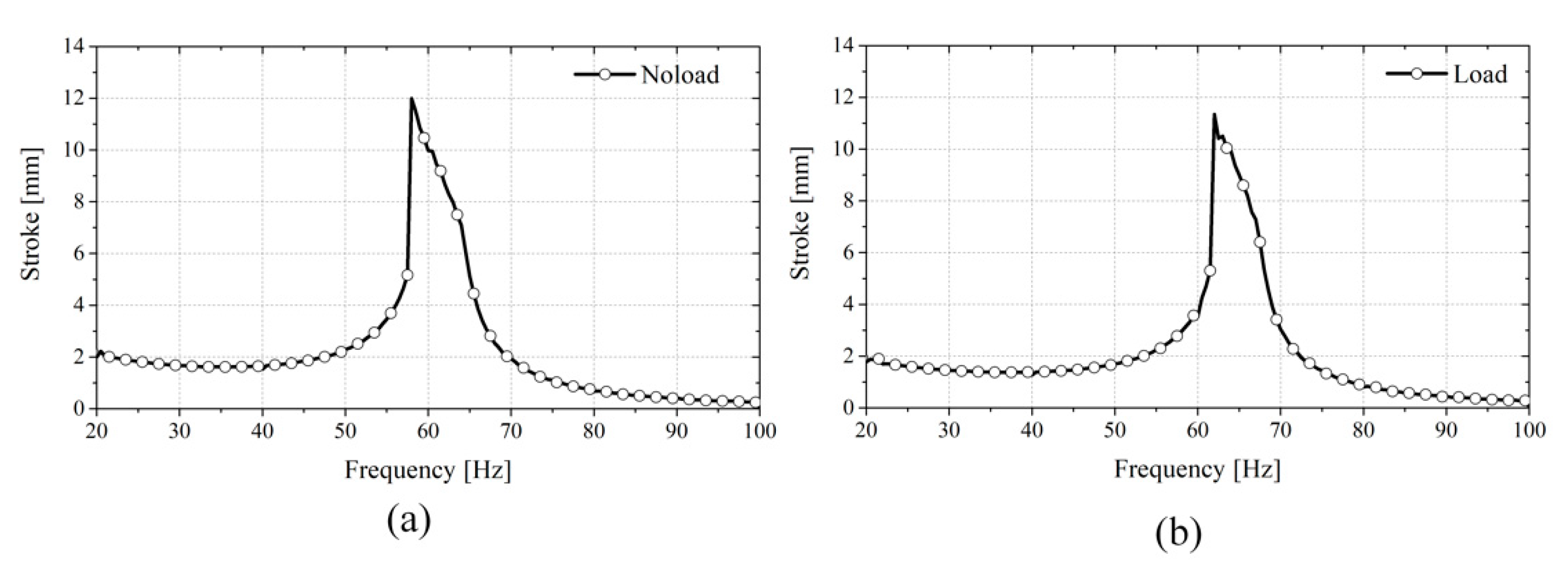
2.4. Dynamic Characteristic of LOM

Figure 11 shows the equivalent electrical circuit, including the mechanical system, which includes load force, spring coefficient, damping coefficient, and mover mass. The analysis of the dynamic characteristic of the LOM, considering the mechanical system, can be calculated from the equations of voltage and motion of the LOM. In the LOM, the back EMF is in series with the stator winding resistance and inductance and is proportional to the speed. The voltage equation of LOM is given by:
V t ( t ) = R p h i ( t ) + L s d i ( t ) d t + K e d x ( t ) d t
where Rph, Ls, Ke, and x are the phase resistance, inductance, back EMF coefficient, and displacement, respectively. Based on Equation (5), the displacement can be derived as:
x ( t ) = 1 K e ( V t R p h i L s d i d t ) d t = 1 K e E d t
Equation (6) shows that the stroke is calculated by integrating the back EMF. The motion equation of mechanical system is given by:
F ( t ) = K T i ( t ) = M d 2 x ( t ) d t 2 + K x ( t ) + C d d x ( t ) d t
where KT and Cd are the thrust and damping coefficients, respectively. The mover mass refers to the effective mass that includes the magnet weight and equivalent mass of the piston, and the damping coefficient refers to the viscous resistance between the piston and wall.
In addition, the spring coefficient is calculated as the sum of the mechanical spring coefficient and discharge pressure that changes depending on the load condition. In this study, only mechanical-spring-coefficient values were considered without considering load conditions. The thrust coefficient is assumed to be constant because although its value varies depending on the position of the mover, the effect is small. The mechanical system constants and resonance frequencies of this analysis model are shown in Table 2. Parameters of LOM are shown in Table 3. In Figure 12, it is possible to confirm the phase and magnitude of the current and displacement at the resonance frequency, and it confirms that a difference of 90 degrees occurs. In addition, Figure 13 shows that the resonant frequency changes according to the change of the machine coefficient under no-load and load conditions.

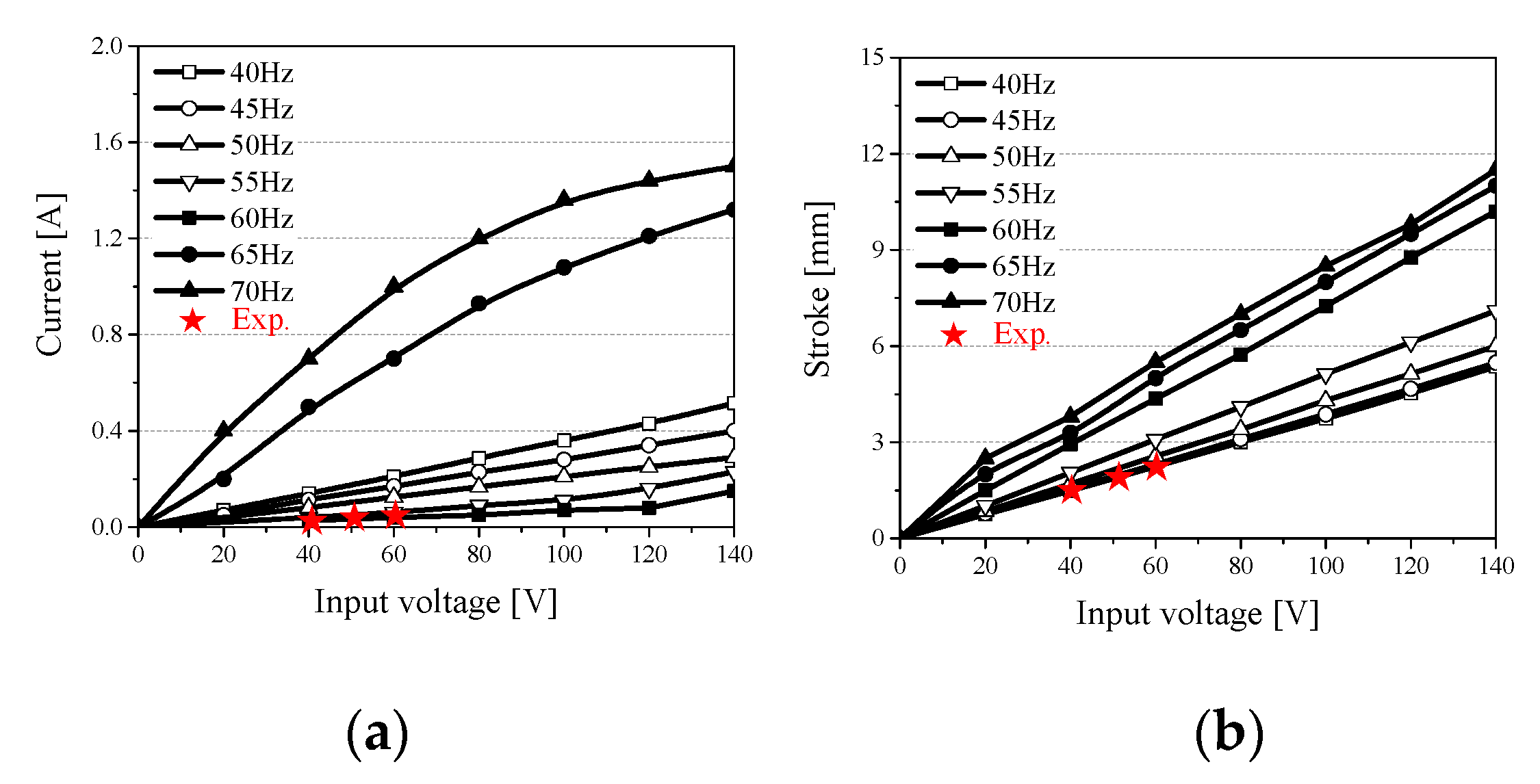
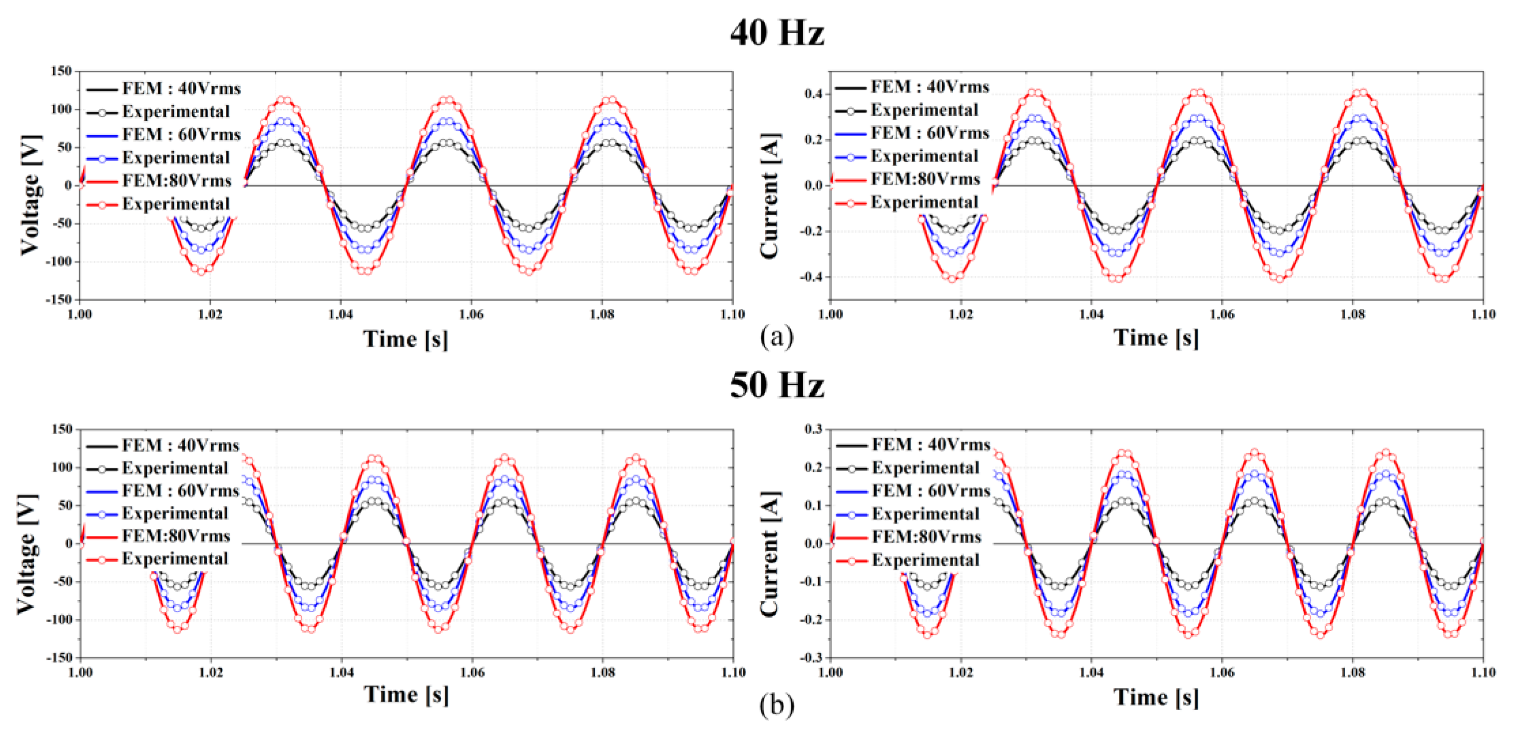
3. Experiment and Discussion

The LOM experiment confirmed the current and stroke of LOM with the applications of function generator and amplifier, respectively. Figure 14 shows the experimental setup consisting of the LOM, linear coupling, position sensor, and indicator. When AC power was applied to the LOM, the mover reciprocated according to the magnitude and direction of the current. Figure 15 shows the results of the transient-behavior analysis of the LOM according to the applied voltage and frequency. The results of the stroke analysis presented in Figure 15a display the current magnitude, where the smallest current is observed at the resonance frequency. Further, Figure 15b show that the largest stroke is produced at the resonance frequency. This is because when the resonance frequency and electrical resonance frequency are the same, the loss of components due to the mover mass and spring disappears so that the most efficient operation is possible. Figure 16 shows the analysis results and experimental results for the applied voltage and current waveform at 40 Hz and 50 Hz.

4. Conclusions

This paper introduced the structure and operating principle of the movable-magnet-type LOM with the most efficient and simple magnetic circuit. After moving the magnet at a constant speed to determine the magnetic stroke and inductance of the LOM, the driving characteristics were investigated according to the electrical resonance frequency. The LOM was manufactured. In addition, the transient behavior of the LOM was verified by applying an AC voltage. To analyze the transient-behavior characteristics, an analysis was conducted by considering the mechanical-system elements such as spring, damping coefficient, and mover mass. Finally, by using the analysis based on the input voltage and frequency, the authors confirmed that the most efficient operation is possible when the electrical resonance frequency and resonance frequency of the LOM match.

Author Contributions

J.-Y.C.: conceptualization, review and editing; W.-H.K.: original draft preparation, formal analysis, and validation; C.-W.K.: writing and formal analysis; H.-S.S.: validation and software; K.-H.S.: review and editing. All authors have read and agreed to the published version of the manuscript.

Funding

This research was supported by the Basic Science Research Program through the National Research Foundation of Korea (NRF-2020R1A4A2002021). This research was supported by Korea Electic Power Corporation (Grant number: R20XO02-38).

Data Availability Statement

Data sharing not applicable. Sharing of the results of this study is limited at the request of the company.

Conflicts of Interest

The authors declare no conflict of interest.

References

  1. Wang, J.; Howe, D.; Lin, Z. Design Optimization of Short-Stroke Single-Phase Tubular Permanent-Magnet Motor for Refriger-ation Applications. IEEE Trans. Ind. Electron. 2010, 57, 327–334. [Google Scholar] [CrossRef]
  2. Ibrahim, T.; Wang, J.; Howe, D. Analysis of a single phase, quasi-Halbach magnetised tubular permanent magnet motor with non-ferromagnetic supporting tube. In Proceedings of the 4th IET International Conference on Power Electronics, Machines and Drives (PEMD 2008), York, UK, 2–4 April 2008; pp. 762–766. [Google Scholar]
  3. Zhu, Z.; Chen, X.; Howe, D.; Iwasaki, S. Electromagnetic Modeling of a Novel Linear Oscillating Actuator. IEEE Trans. Magn. 2008, 44, 3855–3858. [Google Scholar] [CrossRef]
  4. Khalid, S.; Khan, F.; Ahmad, Z.; Ullah, B. Design and finite element analysis of modular C-Core stator tubular linear oscillating actuator for miniature compressor. World J. Eng. 2021, ahead-of-print. [Google Scholar] [CrossRef]
  5. Ahmad, Z.; Hassan, A.; Khan, F.; Ahmad, N.; Khan, B.; Ro, J.-S. Analysis and Design of a Novel Outer Mover Moving Magnet Linear Oscillating Actuator for a Refrigeration System. IEEE Access. 2021, 9, 121240–121252. [Google Scholar] [CrossRef]
  6. Chen, H.; Nie, R.; Yan, W. A Novel Structure Single-Phase Tubular Switched Reluctance Linear Motor. IEEE Trans. Magn. 2017, 53, 1–4. [Google Scholar] [CrossRef]
  7. Ahmad, Z.; Hassan, A.; Khan, F.; Lazoglu, I. Design of a high thrust density moving magnet linear actuator with magnetic flux bridge. IET Electr. Power Appl. 2020, 14, 1256–1262. [Google Scholar] [CrossRef]
  8. Xue, X.; Cheng, K.W.E.E.; Zhang, Z. Model, Analysis, and Application of Tubular Linear Switched Reluctance Actuator for Linear Compressors. IEEE Trans. Ind. Electron. 2018, 65, 9863–9872. [Google Scholar] [CrossRef]
  9. Asai, Y.; Ota, T.; Yamamoto, T.; Hirata, K. Proposed of Novel Linear Oscillating Actuator’s Structure Using Topology Optimi-zation. IEEE Trans. Magn. 2017, 53, 1–4. [Google Scholar] [CrossRef]
  10. Roemer, D.B.; Bech, M.M.; Johansen, P.; Pedersen, H.C. Optimum Design of a Moving Coil Actuator for Fast-Switching Valves in Digital Hydraulic Pumps and Motors. IEEE/ASME Trans. Mechatron. 2015, 20, 2761–2770. [Google Scholar] [CrossRef]
  11. Al-Otaibi, Z.S. Spring-less permanent magnet linear-resonant motor for compressor applications. In Proceedings of the 2012 IEEE International Conference on Power and Energy (PECon), Kota Kinabalu, Malaysia, 2–5 December 2012; pp. 420–423. [Google Scholar]
  12. Lee, K.-S.; Lee, S.-H.; Park, J.-H.; Choi, J.-Y.; Sim, K.-H. Design and Experimental Analysis of a 3 kW Single-Phase Linear Permanent Magnet Generator for Stirling Engines. IEEE Trans. Magn. 2018, 54, 1–5. [Google Scholar] [CrossRef]
  13. Atallah, K.; Howe, D.; Mellor, P.; Stone, D. Rotor loss in permanent magnet brushless AC machines. In Proceedings of the IEEE International Electric Machines and Drives Conference. IEMDC’99., Seattle, WA, USA, 9–12 May 1999; pp. 60–62. [Google Scholar] [CrossRef]
  14. Bertotti, G. General properties of power losses in soft ferromagnetic materials. IEEE Trans. Magn. 1988, 24, 621–630. [Google Scholar] [CrossRef]
  15. Nam, H.; Ha, K.-H.; Lee, J.-J.; Hong, J.-P.; Kang, G.-H. A study on iron loss analysis method considering the harmonics of the flux density waveform using iron loss curves tested on epstein samples. IEEE Trans. Magn. 2003, 39, 1472–1475. [Google Scholar] [CrossRef]
Figure 1. (a) Two-dimensional analysis model of LOM, (b) 3D analysis model of LOM, (c) manufactured components of linear oscillating machine.
Machines 10 00048 g001
Figure 2. Magnetic flux density and flow of the LOM.
Machines 10 00048 g002
Figure 3. Back EMF and magnetic force according to mover position.
Machines 10 00048 g003
Figure 4. Inductance of LOM according to mover position and input current.
Machines 10 00048 g004
Figure 5. Copper loss analysis result according to applied current.
Machines 10 00048 g005
Figure 6. (a) Loss comparison according to the number of permanent magnets; (b) Eddy current loss comparison according to the number of permanent magnet divisions.
Machines 10 00048 g006
Figure 7. (a) Stator analysis model for core loss analysis; (b) Conceptual diagram of axis ratio.
Machines 10 00048 g007
Figure 8. Flux density in each point of stator according to flux direction: (a) radial and (b) axial.
Machines 10 00048 g008
Figure 9. Magnetic field behavior according to stator region: (a) region 1, (b) region 6, (c) region 16, (d) region 25, (e) region 28, (f) region 32.
Machines 10 00048 g009
Figure 10. Core loss analysis result according to driving frequency.
Machines 10 00048 g010
Figure 11. Analysis model including mechanical system of LOA.
Machines 10 00048 g011
Figure 12. Current and displacement analysis results.
Machines 10 00048 g012
Figure 13. Current and displacement analysis results: (a) No load (b) Load.
Machines 10 00048 g013
Figure 14. Experiment set of the LOM.
Machines 10 00048 g014
Figure 15. Transient analysis results of the LOM: (a) current and (b) stroke.
Machines 10 00048 g015
Figure 16. Voltage and current and analysis results and experimental results: (a) 40 Hz (b) 50 Hz.
Machines 10 00048 g016
Table 1. LOM losses and efficiency @ rated load.
Copper LossCore LossSolid LossPowerEfficiency
1.18 W2.85 W0.04 W110 W96.4%
Table 2. Parameters for dynamic analysis of LOM.
ParameterValue
Spring Coefficient34,800 N/m
Damping Coefficient0.9 Ns/m
Mover Mass0.25 kg
Resonance Frequency60 Hz
Table 3. LOM parameters.
ParameterValue
Operating frequency60 Hz
Rated stroke±5 mm
Outer core radius59 mm
Stator typeOuter core
Mover typePM mover
Rated power100 W
Resistance1.11 Ω
Inductance792 mH
Publisher’s Note: MDPI stays neutral with regard to jurisdictional claims in published maps and institutional affiliations.

