Article

Refined Discontinuous Trigger Scheme for Event-Based Synchronization of Chaotic Neural Networks

1
College of Electrical Engineering and Automation, Shandong University of Science and Technology, Qingdao 266590, China
2
School of Science, Qingdao University of Technology, Qingdao 266520, China
*
Author to whom correspondence should be addressed.
Axioms 2025, 14(6), 403; https://doi.org/10.3390/axioms14060403
Submission received: 26 March 2025 / Revised: 20 May 2025 / Accepted: 21 May 2025 / Published: 26 May 2025
(This article belongs to the Section Mathematical Analysis)

Abstract

This paper is concerned with the event-based synchronization control for chaotic neural networks by using a refined discontinuous trigger scheme. To get rid of the Zeno phenomenon and decrease the triggering times, a refined discontinuous event-trigger (RDET) scheme is employed by designing a new threshold function. The proposed threshold function consists of two parts, i.e., quadratic term and exponential decay term, which makes the derivative of the Lyapunov function possibly not less than zero. On this basis, an important lemma is derived, which contributes to performing a stability analysis. Then, the corresponding closed-loop system model is established in the presence of a trigger scheme. Then, a time-dependent Lyapunov function (TLF) method is established based on the features of an RDET. In view of inequality estimation techniques and stability theory, some synchronization criteria are developed to guarantee that the synchronization of chaotic neural networks can be realized by using the novel discontinuous event-trigger schemes. Finally, a Hopfield neural network is displayed to demonstrate the advantages and effectiveness of the derived results.

1. Introduction

Neural networks (NNs) are derived from the operating principles of the biological nervous system [1,2,3,4]. They have the ability to handle vast amounts of complex data, learning patterns and features from the data, and making predictions or decisions. This has brought about innovation and efficiency improvements in various industries. Therefore, in the last decade or thereabouts, NNs have been widely used as a computational tool and, thus, are being applied in image processing, biological systems, fault diagnosis, etc. [5,6]. Complete synchronization means that the same trajectories can be achieved for the drive–response systems. It has important applications in communication security, information science, and so on [7]. In summary, to study the synchronization problem of chaotic neural networks is very important. Up to now, some classical control approaches have been developed in the control field, including adaptive and static control, etc. However, the common characteristic of these control methods is that they are all point-to-point control schemes. Nevertheless, these control schemes can cause a waste of limited information resources. With the rise of the internet technique, networked control has emerged as a result of its energy-saving, promising, and highly fault-tolerant advantages, which includes sampled-data [8], quantized [9], and event-triggered [10] controls.
This paper focuses on the synchronization of chaotic NNs in view of a refined DET scheme. The main contributions are as follows:
(1) An RDET scheme is proposed by designing a new threshold function, which includes a quadratic term and an exponential decay term. In the presence of the RDET scheme, the threshold function can be enlarged due to the introduction of the exponential decay term. Furthermore, the triggering interval is further expanded. This contributes to reducing the triggering times according to the essence of the event trigger. Therefore, the proposed RDET scheme can relieve communication burden in contrast with the proposed one in [10,11].
(2) By designing a switching TLF, two synchronization criteria are obtained based on the continuity of this function and inequality estimation techniques. The Lyapunov theory is applied to prove the effectiveness of the proposed method, that is,  | | ξ ( t ) | | p = 0 . It means that the synchronization of master–slave systems can be achieved. Also, two corollaries can be established by using the previous schemes [10,11]. In light of the derived synchronization results, through examples and applications, we observe that the RDET scheme, compared to traditional DET schemes, achieves synchronization in master–slave neural networks with fewer triggering instances.
The rest of this paper is organized as follows. In Section 2, the related works are presented. In Section 3, a refined trigger scheme is designed, and Section 4 presents the main results. The validity of the developed method is shown in Section 5. Section 6 presents the conclusions.
In addition, some useful notations are displayed in Table 1.

2. Related Works

As a classical networked control method, sampled-data control has the advantage of a low cost, and it is easy to be implemented. However, sampled-data control continues to transmit the sampling data information when stability has been achieved in a closed-loop system. This not only causes a waste of resources but also takes up CPU run-time. In contrast to the sampled-data control, continuous event-triggered control [12,13] allows for a signal transmission only when the error signals exceed pre-assigned threshold functions. As such, it effectively deals with the drawbacks of sampled-data control since event-triggered control provides a workable method for reducing triggering times and easing the transmission burden. For example, quasi-synchronization problems have been investigated for memristive NNs by designing static and dynamic continuous event-trigger schemes [13]. However, an important issue is that the Zeno phenomenon may exist under the framework of continuous event-triggered control. To get rid of the Zeno phenomenon directly, discrete event-triggered schemes [14,15] have been proposed. Nevertheless, this control method does not take advantage of the present state information. To this end, the DET scheme [10,11,16] was designed, which makes full use of state information. Also, the Zeno phenomenon can be avoided. Using the DET scheme, exponential stabilization issues have been discussed for switched NNs by considering mixed delays [10]. In addition, the problems of event-triggered H have been addressed for T-S fuzzy systems in view of the DET scheme [11]. Nonetheless, it should be mentioned that the threshold function just includes the quadratic term of the current state information. From the principle of the event-triggered scheme, we know that the goal of the design is to reduce the triggering times. Moreover, from the perspective of the operation mechanism of the event trigger, generally, a larger threshold function means smaller event-triggered times. However, from reading the literature [10,11], there is still much room for improvement in the design of the event-triggered scheme. As we know, there are few results on this problem. How to design a refined discontinuous event-trigger (RDET) scheme is the first motivation of this paper.
Notice that the other key question is how to analyze the synchronization issue for NNs under event-triggered control. So far, many Lyapunov functions have been proposed in the control community to analyze the corresponding stability. Among them, the traditional Lyapunov function has been used to analyze the exponential stability of linear systems [14,15]. However, it cannot reflect the main features of event-trigger-based systems [16]. Hence, to solve this problem, time-dependent Lyapunov function (TLF) methods were proposed [17], and these methods have been widely used in applications of event-triggered systems. For example, the switching TLF was proposed for the study of the switched systems stabilization issue [18]. Indeed, both theoretical and simulation results show that such functions can improve on previous results. Inspired by this, this paper builds a TLF to analyze the problem of complete synchronization of NNs based on a novel DET scheme. However, it is worth noting that when we introduce a novel trigger scheme, the previous analysis technique and functions may be not applied in this paper. It means that the stability analysis in this paper is a challenging problem. Up till now, there have been few results focused on these problems. Naturally, some challenging problems are proposed: how can one design an RDET scheme by designing a novel threshold function? What are the challenges encountered from stability analysis in the presence of the RDET scheme? Can the proposed novel trigger scheme improve on previous works? Solving these problems is the second motivation of this paper.

3. Preliminaries and Problem Formulation

For industrial applications, NNs can be combined with large-scale integrated circuits [1]. Thus, based on Kirchoff current law and voltage law, the NN model can be presented as follows:
F : ϵ ˙ ( t ) = E ϵ ( t ) + D h ( ϵ ( t ) ) ,
H : ζ ˙ ( t ) = E ζ ( t ) + D h ( ζ ( t ) ) + u ( t ) ,
where  F , H  denote the master–slave NNs, respectively.  E R n × n D R n × n  are known constant matrices.  ϵ ( t ) = col { ϵ 1 ( t ) , ϵ 2 ( t ) , , ϵ n ( t ) } R n ζ ( t ) = col { ζ 1 ( t ) , ζ 2 ( t ) , , ζ n ( t ) } R n  refer to the state vector,  h ( ϵ ( t ) ) = col { h 1 ( ϵ 1 ( t ) ) , h 2 ( ϵ 2 ( t ) ) , , h n ( ϵ n ( t ) ) } R n  represents the activation functions, and  u ( t ) R n  is the slave system control input.
Assumption: The activation function  h j ( · )  is monotonically non-decreasing and Lipschitz-continuous on  R , i.e., there exist constants  H j > 0 j = 1 , 2 , , n , such that
0 h j ( s 1 ) h j ( s 2 ) s 1 s 2 H j
for all  s 1 , s 2 R , s 1 s 2 .
Denote  ξ ( t ) = ζ ( t ) ϵ ( t )  as a synchronization error and one can derive the error system:
ξ ˙ ( t ) = E ξ ( t ) + D h ^ ( ξ ( t ) ) + u ( t )
where  h ^ ( ξ ( t ) ) = h ( ζ ( t ) ) h ( ϵ ( t ) ) .
In this paper, an RDET scheme is proposed as follows:
t k + 1 = min { t t k + h k | ( ξ ( t ) ξ ( t k ) ) T Ω ( ξ ( t ) ξ ( t k ) ) > γ ξ T ( t ) Ω ξ ( t ) + α ( t ) }
where  0 < h 1 h k h 2 γ 0 α ( t ) = ι e β t ι 0 β > 0 , and trigger matrix  Ω 0 .
The RDET scheme is designed to decrease the number of measurements. The working mode of the RDET scheme is as follows. An inner-trigger interval  [ t k , t k + 1 )  contains two parts, namely, sampling interval  [ t k , t k + h k )  and triggering interval  [ t k + h k , t k + 1 ) . When  t [ t k , t k + h k ) , the detection task of the judging conditions is stopped in the trigger scheme. When  t [ t k + h k , t k + 1 ) , the judgment condition gets to work until it is satisfied at  t k + 1 .
Remark 1.
To reduce network bandwidth usage, event-triggered control schemes [12,13] aiming to minimize the number of transmitted data packets have been proposed. However, the aforementioned continuous event-triggered control may result in the Zeno phenomenon, in which an infinite number of triggers occurs within a finite period. In such cases, complex mathematical proofs are required to eliminate the Zeno phenomenon. To directly eliminate the Zeno phenomenon, various solutions such as a discrete event-trigger [14,15] and a DET [10,11] have been proposed. The DET mechanism is as follows:
t k + 1 = min { t t k + h k | ( ξ ( t ) ξ ( t k ) ) T Ω ( ξ ( t ) ξ ( t k ) ) > γ ξ T ( t ) Ω ξ ( t ) } .
It is evident that the DET scheme can effectively utilize the current state information. Furthermore, in this paper, an RDET scheme (2) is proposed, with an exponential decay term introduced into the threshold function. Consequently, the prescribed threshold function is magnified. This is advantageous for further reducing the triggering frequency, minimizing unnecessary data packet transmission, and thereby conserving network resources.
Remark 2.
Notice that if  α ( t ) = 0 , the RDET will be degenerated to the traditional DET [10,11], with the triggering scheme given by (3). It should be mentioned that the trigger event is activated when  ( ξ ( t ) ξ ( t k ) ) T Ω ( ξ ( t ) ξ ( t k ) ) γ ξ T ( t ) Ω ξ ( t ) > 0 . Owing to the existence of  α ( t ) , it is clear that the threshold function can be enlarged. In this condition, the number of trigger events can be decreased based on the RDET (2). Specially, if  α ( t ) = 0 , the previous DET scheme is a special case in this paper.
Take the control inputs as follows:
u ( t ) = K ξ ( t k ) , t [ t k , t k + 1 )
where K stands for feedback gain matrix. Based on (4), system (1) is represented as
ξ ˙ ( t ) = E ξ ( t ) + D h ^ ( ξ ( t ) ) + K ξ ( t k ) , t [ t k , t k + 1 )
Before providing the main works, a novel lemma is established, which is important to prove the stability of system (5).
Lemma For system (5), denote a non-negative and continuous Lyapunov function  V ( t )  for which there exist constants  δ > 0 μ > 0 0 < υ 1 < υ 2 , and  0 < h 1 h k h 2  such that  υ 1 | ξ ( t ) | μ V ( t ) υ 2 | ξ ( t ) | μ , and
V ˙ ( t ) 2 δ V ( t ) , t [ t k , t k + h k ) ,
V ˙ ( t ) 2 δ V ( t ) + α ( t ) , t [ t k + h k , t k + 1 ) ,
where  α ( t ) = ι e β t ι 0 β > 0 ; then, the closed-loop system (5) is globally asymptotically stable.
Proof. 
If  t [ t k + h k , t k + 1 ) , from (6) and (7), we have
V ( t ) ( 7 ) e 2 δ ( t ( t k + h k ) ) V ( t k + h k ) + t k + h k t α ( s ) e 2 δ ( t s ) d s ( 6 ) e 2 δ ( t ( t k + h k ) ) e 2 δ ( t k + h k t k ) V ( t k ) + t k t α ( s ) e 2 δ ( t s ) d s ( 7 ) e 2 δ ( t t k ) ( e 2 δ ( t k ( t k 1 + h k 1 ) ) V ( t k 1 + h k 1 ) + t k 1 + h k 1 t k α ( s ) e 2 δ ( t k s ) d s ) + t k t α ( s ) e 2 δ ( t s ) d s ( 6 ) e 2 δ ( t t k 1 ) V ( t k 1 ) + t k 1 t α ( s ) e 2 δ ( t s ) d s ( 7 ) ( 6 ) e 2 δ t V ( 0 ) + 0 t α ( s ) e 2 δ ( t s ) d s
Also, if  t [ t k , t k + h k ) , one has
V ( t ) ( 6 ) e 2 δ ( t t k ) V ( t k ) ( 7 ) e 2 δ ( t t k ) ( e 2 δ ( t k ( t k 1 + h k 1 ) ) V ( t k 1 + h k 1 ) + t k 1 + h k 1 t k α ( s ) e 2 δ ( t k s ) d s ) ( 6 ) e 2 δ ( t t k 1 ) V ( t k 1 ) + t k 1 t α ( s ) e 2 δ ( t s ) d s ( 7 ) ( 6 ) e 2 δ t V ( 0 ) + 0 t α ( s ) e 2 δ ( t s ) d s
From the above analysis, for  t [ t k , t k + 1 ) , one has
V ( t ) e 2 δ t V ( 0 ) + 0 t α ( s ) e 2 δ ( t s ) d s = e 2 δ t V ( 0 ) + ι 0 t e β s e 2 δ ( t s ) d s = e 2 δ t V ( 0 ) + ι e 2 δ t 0 t e ( 2 δ β ) s d s .
Considering the term  2 δ β , when  2 δ β = 0 , in other words,  δ = β / 2 , one can obtain
V ( t ) e β t ( V ( 0 ) + ι t ) .
When  2 δ β 0 , it yields
V ( t ) e 2 δ t ( V ( 0 ) ι 2 δ β ) + ι e β t 2 δ β .
In short, when  δ > 0 ι 0 β > 0 , one has
lim t + V ( t ) = 0 .
Hence, system (5) is globally asymptotically stable. This completes the proof. □

4. Main Results

Theorem 1.
For given constants  0 < h 1 h 2 δ > 0 γ 0 , and an  n × n  feedback gain matrix K, if there exist  n × n  matrices  P > 0 ,   S > 0 ,   Ω 0 , an  n × n  diagonal matrix  Λ 1 > 0 , and any  n × n  matrices  U 1 , U 2 , U 3 , X , X 1 , Y 1 , Y 2  satisfying the following constraints for  h k { h 1 , h 2 } :
P + h k X + X T 2 h k ( X + X 1 ) * h k ( X 1 X 1 T + X + X T 2 ) > 0 ,
Φ ( h k ) 0 ,
Ψ ( h k ) 0 ,
Γ 0 ,
where  Φ 11 = X + X T 2 U 1 U 1 T Y 1 T E E T Y 1 + 2 δ P + 2 δ h k X + X T 2 Φ 12 = P Y 1 T U 2 E T Y 2 + h k X + X T 2 Φ 13 = X X 1 + U 1 T U 3 + Y 1 T K + 2 δ h k ( X + X 1 ) Φ 14 = L Λ 1 + Y 1 T D Φ 22 = Y 2 Y 2 T + h k S Φ 23 = U 2 T + Y 2 T K + h k ( X + X 1 ) Φ 24 = Y 2 T D Φ 33 = X 1 + X 1 T X + X T 2 + U 3 + U 3 T + 2 δ h k ( X 1 X 1 T + X + X T 2 ) Φ 44 = 2 Λ 1 Ψ 11 = X + X T 2 U 1 U 1 T Y 1 T E E T Y 1 + 2 δ P Ψ 12 = P Y 1 T U 2 E T Y 2 Ψ 13 = X X 1 + U 1 T U 3 + Y 1 T K Ψ 14 = h k U 1 T Ψ 15 = L Λ 1 + Y 1 T D Ψ 22 = Y 2 Y 2 T Ψ 23 = U 2 T + Y 2 T K Ψ 24 = h k U 2 T Ψ 25 = Y 2 T D Ψ 33 = X 1 + X 1 T X + X T 2 + U 3 + U 3 T Ψ 34 = h k U 3 T Ψ 44 = h k e 2 δ h 2 S Ψ 55 = 2 Λ 1 Γ 11 = Y 1 T E E T Y 1 + γ Ω Ω + 2 δ P Γ 12 = P Y 1 T E T Y 2 Γ 13 = Y 1 T K + Ω Γ 14 = Y 1 T D + L Λ 1 Γ 22 = Y 2 Y 2 T Γ 23 = Y 2 T K Γ 24 = Y 2 T D Γ 33 = Ω Γ 44 = 2 Λ 1 , then system (5) is globally asymptotically stable.
Proof. 
Choose the time-dependent Lyapunov function
V 1 ( t ) = ξ T ( t ) P ξ ( t ) ,
V 2 ( t ) = ( t k + h k t ) t k t e 2 δ ( s t ) ξ ˙ T ( s ) S ξ ˙ ( s ) d s ,
V 3 ( t ) = ( t k + h k t ) ξ ( t ) ξ ( t k ) T H ξ ( t ) ξ ( t k ) ,
where  H = X + X T 2 X + X 1 * X 1 X 1 T + X + X T 2 .
Differentiating  V i ( t ) i = 1 , 2 , 3 , one has
V ˙ 1 ( t ) = 2 ξ T ( t ) P ξ ˙ ( t ) ,
V ˙ 2 ( t ) = t k t e 2 δ ( s t ) ξ ˙ T ( s ) S ξ ˙ ( s ) d s + ( t k + h k t ) ξ ˙ T ( t ) S ξ ˙ ( t ) 2 δ V 2 ( t ) ,
V ˙ 3 ( t ) = ξ ( t ) ξ ( t k ) T H ξ ( t ) ξ ( t k ) + 2 ( t k + h k t ) ξ ( t ) ξ ( t k ) T H ξ ˙ ( t ) 0 .
Define
V π ( t ) = V π 1 ( t ) , t [ t k , t k + h k ) V π 2 ( t ) , t [ t k + h k , t k + 1 )
where  V π 1 ( t ) = V 1 ( t ) + V 2 ( t ) + V 3 ( t ) , V π 2 ( t ) = V 1 ( t ) .
Case I: When  t [ t k , t k + h k ) , based on Jensen inequality, it yields
t k t e 2 δ ( s t ) ξ ˙ T ( s ) S ξ ˙ ( s ) d s ( t t k ) e 2 δ h 2 v 1 T S v 1 ,
where  v 1 = 1 t t k t k t ξ ˙ ( s ) d s .
Under Assumption 1, for a diagonal matrix  Λ 1 > 0 , it yields
2 h ^ T ( ξ ( t ) ) Λ 1 L ξ ( t ) 2 h ^ T ( ξ ( t ) ) Λ 1 h ^ ( ξ ( t ) ) 0 ,
where  L = diag ( H 1 , , H n ) .
Meanwhile, by applying the Newton–Leibniz formula, for  n × n  matrices  U 1 , U 2 , U 3 , it holds that
0 = 2 [ ξ T ( t ) U 1 T + ξ ˙ T ( t ) U 2 T + ξ T ( t k ) U 3 T ] × [ ξ ( t ) + ξ ( t k ) + ( t t k ) v 1 ] .
Also, for any matrices  Y 1 , Y 2 R n × n , it can be derived that
0 = 2 [ ξ T ( t ) Y 1 T + ξ ˙ T ( t ) Y 2 T ] × [ ξ ˙ ( t ) E ξ ( t ) + D h ^ ( ξ ( t ) ) + K ξ ( t k ) ] ,
From (12)–(15), one can obtain
V ˙ π 1 ( t ) + 2 δ V π 1 t k + h k t h k χ 1 T Φ ( h k ) χ 1 + t t k h k χ 2 T Ψ ( h k ) χ 2 .
where  χ 1 ( t ) = col { ξ ( t ) , ξ ˙ ( t ) , ξ ( t k ) , h ^ ( ξ ( t ) ) } χ 2 ( t ) = col { ξ ( t ) , ξ ˙ ( t ) , ξ ( t k ) , v 1 , h ^ ( ξ ( t ) ) } .
Combined with the convex combination technique [17], (9), and (10), obviously, the conditions  Φ ( h 1 ) < 0 , Φ ( h 2 ) < 0 , Ψ ( h 1 ) < 0 , Ψ ( h 2 ) < 0  hold, which yields  Φ ( h k ) < 0 , Ψ ( h k ) < 0 h k [ h 1 , h 2 ] .
So, one can obtain
V ˙ π 1 ( t ) + 2 δ V π 1 0 .
Case II: When  t [ t k + h k , t k + 1 ) , from (2), one has
γ ξ T ( t ) Ω ξ ( t ) ( ξ ( t ) ξ ( t k ) ) T Ω ( ξ ( t ) ξ ( t k ) ) + α ( t ) 0 .
Based on (13), (15), and (17), one has
V ˙ π 2 ( t ) + 2 δ V π 2 χ 1 T Γ χ 1 + α ( t ) .
From (11), it yields
V ˙ π 2 ( t ) + 2 δ V π 2 α ( t ) .
Note that  V 2 ( t ) , V 3 ( t )  vanish at  t k  and  t k + h k . Hence,  V π ( t )  is continuous at time instants  t k  and  t k + h k . From (16) and (18), one can obtain
V ˙ π 1 ( t ) 2 δ V π 1 , t [ t k , t k + h k ) V ˙ π 2 ( t ) 2 δ V π 2 + α ( t ) , t [ t k + h k , t k + 1 )
It should be mentioned that  V π ( t ) = V π 1 ( t ) , t [ t k , t k + h k ) V π 2 ( t ) , t [ t k + h k , t k + 1 )  is positive and continuous. Then, based on Lemma 1, we can obtain
lim t + V π ( t ) = 0 .
Hence, system (5) is globally asymptotically stable. This completes the proof. □
Remark 3.
The first challenge in this paper is to establish stability criteria for the error system (5). As is well known, based on the traditional Lyapunov stability theory, if there exists a Lyapunov function  V ( t )  satisfying the conditions  V ( t ) > 0  and  V ˙ ( t ) < 0 , then the stability of the system can be ensured. In the sampling interval  [ t k , t k + h k ) , as shown in (6),  V ( t )  strictly decreases. However, in the triggering interval  [ t k + h k , t k + 1 ) V ( t )  may be greater than zero due to the introduction of the exponential decay term  α ( t ) . In other words, the conservatism of  V ˙ ( t )  is reduced and  V ˙ ( t ) 2 δ V ( t ) + α ( t )  with  α ( t ) > 0 . The traditional Lyapunov stability theory is no longer applicable. To address this, based on the continuity of non-negative Lyapunov functions, inequality estimation techniques, mathematical skills, and the designed exponential decay term  α ( t ) = ι e β t , the global asymptotic stability of the error system (5) can be achieved. In summary, the stability analysis in this paper consists of the following two steps. Firstly, an estimation is performed for  V ( t )  in  [ t k , t k + h k )  and  [ t k + h k , t k + 1 ) , respectively. Then, the stability of the error system (5) is analyzed in the inner-trigger interval  [ t k , t k + 1 ) .
Remark 4.
The second challenge in this paper is to design a suitable Lyapunov function and obtain feasible LMIs criteria under the RDET scheme. In [10,16], Lyapunov functions are constructed based on the characteristics of the triggering scheme, where [12,13] is based on continuous event-triggered control, [14,15] is based on discrete event-triggered control, and [10,11,16] is based on DET control. However, the aforementioned Lyapunov functions cannot be directly applied to RDET due to the introduction of the exponential decay term. Thus, to obtain sufficient conditions (6) and (7) for the asymptotic stability of the error system (5),  V 2 ( t )  is specifically constructed. It is worth noting that, in this paper, Lyapunov functions are constructed based on the current state information  ξ ( t )  in both the error system and the controller, as well as the state information  ξ ( t k )  at the previous triggering instant. Therefore, based on the constructed functionals, the LMI-based stability conditions with feasible solutions can be established. Additionally, to obtain some feasible LMIs, the convex combination technique is applied to transform (8)–(11) into linear LMIs. For instance, there exists a convex combination technique  ϱ k [ 0 , 1 ]  such that  h k = ϱ k h 1 + ( 1 ϱ k ) h 2 ; thus,  Φ ( h k ) = ( 1 ϱ k ) Φ ( h 2 ) + ϱ k Φ ( h 1 ) Φ ( h 1 ) 0 Φ ( h 2 ) 0  mean  Φ ( h k ) 0 .
Remark 5.
The prerequisite of choosing RDET parameters is that the LMIs conditions in Theorems 1 and 2 must be satisfied. On this basis, the synchronization can be achieved. That is to say, the choosing of RDET parameters is not arbitrary.
Remark 6.
Notice that the proposed  V π ( t )  is continuous. It can be seen that  V 2 ( t k ) = lim t ( t k ) + V 2 ( t ) = V 3 ( t ) = lim t ( t k ) + V 3 ( t ) = 0 lim t ( t k + h k ) V 2 ( t ) = lim t ( t k + h k ) V 3 ( t ) = 0 . Also,  V 2 ( t ) V 3 ( t )  vanish after  t k + h k . This yields  lim t ( t k ) V π ( t ) = lim t ( t k ) + V π ( t ) = V π ( t k ) = V 1 ( t k ) lim t ( t k + h k ) V π ( t ) = lim t ( t k + h k ) + V π ( t ) = V π ( t k + h k ) = V 1 ( t k + h k ) .
Next, the linear inequality conditions, based on Theorem 1, are derived to solve feedback control gain K.
Theorem 2.
For given constants  0 < h 1 h 2 l 1 > 0 l 2 > 0 δ > 0 γ 0 , if there exist  n × n  matrices  P ˜ > 0 S ˜ > 0 Ω ˜ 0 ; an  n × n  diagonal matrix  Λ > 0 ; and any  n × n  matrices  U ˜ 1 U ˜ 2 U ˜ 3 X ˜ X ˜ 1 , Y,  K ˜  satisfying the following constraints for any  h k { h 1 , h 2 } :
P ˜ + h k X ˜ + X ˜ T 2 h k ( X ˜ + X ˜ 1 ) * h k ( X ˜ 1 X ˜ 1 T + X ˜ + X ˜ T 2 ) > 0 ,
Φ ˜ ( h k ) 0 ,
Ψ ˜ ( h k ) 0 ,
Γ ˜ 0 ,
where  Φ ˜ 11 = X ˜ + X ˜ T 2 U ˜ 1 U ˜ 1 T l 1 E Y ˜ l 1 Y ˜ T E T + 2 δ P ˜ + 2 δ h k X ˜ + X ˜ T 2 Φ ˜ 12 = P ˜ l 1 Y ˜ U ˜ 2 l 2 Y ˜ T E T + h k X ˜ + X ˜ T 2 Φ ˜ 13 = X ˜ X ˜ 1 + U ˜ 1 T U ˜ 3 + l 1 K ˜ + 2 δ h k ( X ˜ + X ˜ 1 ) Φ ˜ 14 = Y ˜ T L + l 1 D Λ Φ ˜ 22 = l 2 Y ˜ l 2 Y ˜ T + h k S ˜ Φ ˜ 23 = U ˜ 2 T + l 2 K ˜ + h k ( X ˜ + X ˜ 1 ) Φ ˜ 24 = l 2 D Λ Φ ˜ 33 = X ˜ 1 + X ˜ 1 T X ˜ + X ˜ T 2 + U ˜ 3 + U ˜ 3 T + 2 δ h k ( X ˜ 1 X ˜ 1 T + X ˜ + X ˜ T 2 ) Φ ˜ 44 = 2 Λ T Ψ ˜ 11 = 2 δ P ˜ X ˜ + X ˜ T 2 U ˜ 1 U ˜ 1 T l 1 E Y ˜ l 1 Y ˜ T E T Ψ ˜ 12 = P ˜ l 1 Y ˜ U ˜ 2 l 2 Y ˜ T E T Ψ ˜ 13 = X ˜ X ˜ 1 + U ˜ 1 T U ˜ 3 + l 1 K ˜ Ψ ˜ 14 = h k U ˜ 1 T Ψ ˜ 15 = Y ˜ T L + l 1 D Λ Ψ ˜ 22 = l 2 Y ˜ l 2 Y ˜ T Ψ ˜ 23 = U ˜ 2 T + l 2 K ˜ Ψ ˜ 24 = h k U ˜ 2 T Ψ ˜ 25 = l 2 D Λ Ψ ˜ 33 = X ˜ 1 + X ˜ 1 T X ˜ + X ˜ T 2 + U ˜ 3 + U ˜ 3 T Ψ ˜ 34 = h k U ˜ 3 T Ψ ˜ 44 = h k e ˜ 2 δ h 2 S Ψ ˜ 55 = 2 Λ T Γ ˜ 11 = 2 δ P ˜ l 1 E Y ˜ l 1 Y ˜ T E T + γ Ω ˜ Ω ˜ Γ ˜ 12 = P ˜ l 1 Y ˜ l 2 Y ˜ T E T Γ ˜ 13 = l 1 K ˜ + Ω ˜ Γ ˜ 14 = l 1 D Λ + Y ˜ T L Γ ˜ 22 = l 2 Y ˜ l 2 Y ˜ T Γ ˜ 23 = l 2 K ˜ Γ ˜ 24 = l 2 D Λ Γ ˜ 33 = Ω ˜ Γ ˜ 44 = 2 Λ T ; in addition,  K = K ˜ Y ˜ 1 ; then, system (5) is globally asymptotically stable.
Proof. 
Denote  Y 1 = l 1 Y Y 2 = l 2 Y Y ˜ = Y 1 Λ = Λ 1 1 P ˜ = Y ˜ T P Y ˜ S ˜ = Y ˜ T S Y ˜ Ω ˜ = Y ˜ T Ω Y ˜ U ˜ 1 = Y ˜ T U 1 Y ˜ U ˜ 2 = Y ˜ T U 2 Y ˜ U ˜ 3 = Y ˜ T U 3 Y ˜ X ˜ = Y ˜ T X Y ˜ X ˜ 1 = Y ˜ T X 1 Y ˜ , and  χ 1 = diag { Y ˜ , Y ˜ } χ 2 = diag { Y ˜ , Y ˜ , Y ˜ , Λ } χ 3 = diag { Y ˜ , Y ˜ , Y ˜ , Y ˜ , Λ } .
Pre-multiply and post-multiply (8) by  χ 1 T  and  χ 1 , (9) by  χ 2 T  and  χ 2 , (10) by  χ 3 T  and  χ 3 , and (11) by  χ 2 T  and  χ 2 , respectively; (19)–(22) can be obtained. This completes the proof. □
In order to show the advantages of (2) in the simulation section, the following results are derived by using the DET scheme (3) in [10,11].
Corollary 1.
For given constants  0 < h 1 h 2 γ 0 , and an  n × n  feedback gain matrix K, if there exist  n × n  matrices  P > 0 S > 0 Ω 0 ; an  n × n  diagonal matrix  Λ 1 > 0 ; and any  n × n  matrices  U 1 U 2 U 3 , X,  X 1 Y 1 Y 2  satisfying (8) and the following constraints for  h k { h 1 , h 2 } :
Φ ( h k ) 0 ,
Ψ ( h k ) 0 ,
Γ 0 ,
where  Φ 11 = X + X T 2 U 1 U 1 T Y 1 T E E T Y 1 Φ 12 = P Y 1 T U 2 E T Y 2 + h k X + X T 2 Φ 13 = X X 1 + U 1 T U 3 + Y 1 T K Φ 14 = L Λ 1 + Y 1 T D Φ 22 = Y 2 Y 2 T + h k S Φ 23 = U 2 T + Y 2 T K + h k ( X + X 1 ) Φ 24 = Y 2 T D Φ 33 = X 1 + X 1 T X + X T 2 + U 3 + U 3 T Φ 44 = 2 Λ 1 Ψ 11 = X + X T 2 U 1 U 1 T Y 1 T E E T Y 1 Ψ 12 = P Y 1 T U 2 E T Y 2 Ψ 13 = X X 1 + U 1 T U 3 + Y 1 T K Ψ 14 = h k U 1 T Ψ 15 = L Λ 1 + Y 1 T D Ψ 22 = Y 2 Y 2 T Ψ 23 = U 2 T + Y 2 T K Ψ 24 = h k U 2 T Ψ 25 = Y 2 T D Ψ 33 = X 1 + X 1 T X + X T 2 + U 3 + U 3 T Ψ 34 = h k U 3 T Ψ 44 = h k S Ψ 55 = 2 Λ 1 Γ 11 = Y 1 T E E T Y 1 + γ Ω Ω Γ 12 = P Y 1 T E T Y 2 Γ 13 = Y 1 T K + Ω Γ 14 = Y 1 T D + L Λ 1 Γ 22 = Y 2 Y 2 T Γ 23 = Y 2 T K Γ 24 = Y 2 T D Γ 33 = Ω Γ 44 = 2 Λ 1 ; then, system (5) is globally asymptotically stable.
Proof. 
Take the time-dependent Lyapunov function
V 1 ( t ) = ξ T ( t ) P ξ ( t ) ,
V 2 ( t ) = ( t k + h k t ) t k t ξ ˙ T ( s ) S ξ ˙ ( s ) d s ,
V 3 ( t ) = ( t k + h k t ) ξ ( t ) ξ ( t k ) T H ξ ( t ) ξ ( t k ) ,
where  H = X + X T 2 X + X 1 * X 1 X 1 T + X + X T 2 .
Similarly, one has
V ˙ 1 ( t ) = 2 ξ T ( t ) P ξ ˙ ( t ) ,
V ˙ 2 ( t ) = t k t ξ ˙ T ( s ) S ξ ˙ ( s ) d s + ( t k + h k t ) ξ ˙ T ( t ) S ξ ˙ ( t ) ,
V ˙ 3 ( t ) = ξ ( t ) ξ ( t k ) T H ξ ( t ) ξ ( t k ) + 2 ( t k + h k t ) ξ ( t ) ξ ( t k ) T H ξ ˙ ( t ) 0 .
Define
V π ( t ) = V π 1 ( t ) , t [ t k , t k + h k ) V π 2 ( t ) , t [ t k + h k , t k + 1 )
where  V π 1 ( t ) = V 1 ( t ) + V 2 ( t ) + V 3 ( t ) , V π 2 ( t ) = V 1 ( t ) .
Case I: When  t [ t k , t k + h k ) , based on the Jensen inequality, it yields
t k t ξ ˙ T ( s ) S ξ ˙ ( s ) d s ( t t k ) v 1 T S v 1 ,
where  v 1 = 1 t t k t k t ξ ˙ ( s ) d s .
From (13)–(15) and (26), it yields
V ˙ π 1 ( t ) t k + h k t h k χ 1 T Φ ( h k ) χ 1 + t t k h k χ 2 T Ψ ( h k ) χ 2 .
where  χ 1 ( t ) = col { ξ ( t ) , ξ ˙ ( t ) , ξ ( t k ) , h ^ ( ξ ( t ) ) } χ 2 ( t ) = col { ξ ( t ) , ξ ˙ ( t ) , ξ ( t k ) , v 1 , h ^ ( ξ ( t ) ) } .
Combined with the convex combination technique and (23), (24), obviously, the conditions  Φ ( h 1 ) 0 , Φ ( h 2 ) 0 , Ψ ( h 1 ) 0 , Ψ ( h 2 ) 0  hold; this yields  Φ ( h k ) 0 , Ψ ( h k ) 0 h k [ h 1 , h 2 ] .
So, one has
V ˙ π 1 ( t ) 0 .
Case II: When  t [ t k + h k , t k + 1 ) , from (3), one has
γ ξ T ( t ) Ω ξ ( t ) ( ξ ( t ) ξ ( t k ) ) T Ω ( ξ ( t ) ξ ( t k ) ) 0 .
Based on (13), (15), and (27), one has
V ˙ π 2 ( t ) χ 1 T Γ χ 1 .
From (25), it yields
V ˙ π 2 ( t ) 0 .
It should be mentioned that  V π j  is positive while  V ˙ π j ( j = 1 , 2 )  is negative in the sampling interval and triggering interval, respectively. Then, one can obtain
lim t + ξ ( t ) = 0 .
That is to say, for any initial values  ξ ( 0 ) , system (5) converges asymptotically to the origin under the discontinuous event-trigger scheme. □
Corollary 2.
For given constants  0 < h 1 h 2 , l 1 > 0 , l 2 > 0 γ 0 , if there exist  n × n  matrices  P ˜ > 0 , S ˜ > 0 , Ω ˜ 0 ; an  n × n  diagonal  Λ > 0 ; and any  n × n  matrices  U ˜ 1 , U ˜ 2 , U ˜ 3 , X ˜ , X ˜ 1 , Y , K ˜  satisfying (19) and the following constraints for  h k { h 1 , h 2 } :
Φ ˜ ( h k ) 0 ,
Ψ ˜ ( h k ) 0 ,
Γ ˜ 0 ,
where  Φ ˜ 11 = X ˜ + X ˜ T 2 U ˜ 1 U ˜ 1 T l 1 E Y ˜ l 1 Y ˜ T E T Φ ˜ 12 = P ˜ l 1 Y ˜ U ˜ 2 l 2 Y ˜ T E T + h k X ˜ + X ˜ T 2 Φ ˜ 13 = X ˜ X ˜ 1 + U ˜ 1 T U ˜ 3 + l 1 K ˜ Φ ˜ 14 = Y ˜ T L + l 1 D Λ Φ ˜ 22 = l 2 Y ˜ l 2 Y ˜ T + h k S ˜ Φ ˜ 23 = U ˜ 2 T + l 2 K ˜ + h k ( X ˜ + X ˜ 1 ) Φ ˜ 24 = l 2 D Λ Φ ˜ 33 = X ˜ 1 + X ˜ 1 T X ˜ + X ˜ T 2 + U ˜ 3 + U ˜ 3 T Φ ˜ 44 = 2 Λ T Ψ ˜ 11 = X ˜ + X ˜ T 2 U ˜ 1 U ˜ 1 T l 1 E Y ˜ l 1 Y ˜ T E T Ψ ˜ 12 = P ˜ l 1 Y ˜ U ˜ 2 l 2 Y ˜ T E T Ψ ˜ 13 = X ˜ X ˜ 1 + U ˜ 1 T U ˜ 3 + l 1 K ˜ Ψ ˜ 14 = h k U ˜ 1 T Ψ ˜ 15 = Y ˜ T L + l 1 D Λ Ψ ˜ 22 = l 2 Y ˜ l 2 Y ˜ T Ψ ˜ 23 = U ˜ 2 T + l 2 K ˜ Ψ ˜ 24 = h k U ˜ 2 T Ψ ˜ 25 = l 2 D Λ Ψ ˜ 33 = X ˜ 1 + X ˜ 1 T X ˜ + X ˜ T 2 + U ˜ 3 + U ˜ 3 T Ψ ˜ 34 = h k U ˜ 3 T Ψ ˜ 44 = h k S ˜ Ψ ˜ 55 = 2 Λ T Γ ˜ 11 = l 1 E Y ˜ l 1 Y ˜ T E T + γ Ω ˜ Ω ˜ Γ ˜ 12 = P ˜ l 1 Y ˜ l 2 Y ˜ T E T Γ ˜ 13 = l 1 K ˜ + Ω ˜ Γ ˜ 14 = l 1 D Λ + Y ˜ T L Γ ˜ 22 = l 2 Y ˜ l 2 Y ˜ T Γ ˜ 23 = l 2 K ˜ Γ ˜ 24 = l 2 D Λ Γ ˜ 33 = Ω ˜ Γ ˜ 44 = 2 Λ T ; in addition,  K = K ˜ Y ˜ 1 ; then, system (5) is globally asymptotically stable.
Proof. 
Denote  Y 1 = l 1 Y Y 2 = l 2 Y Y ˜ = Y 1 Λ = Λ 1 1 P ˜ = Y ˜ T P Y ˜ S ˜ = Y ˜ T S Y ˜ Ω ˜ = Y ˜ T Ω Y ˜ U ˜ 1 = Y ˜ T U 1 Y ˜ U ˜ 2 = Y ˜ T U 2 Y ˜ U ˜ 3 = Y ˜ T U 3 Y ˜ X ˜ = Y ˜ T X Y ˜ X ˜ 1 = Y ˜ T X 1 Y ˜ , and  χ 1 = diag ( Y ˜ , Y ˜ ) χ 2 = diag ( Y ˜ , Y ˜ , Y ˜ , Λ ) χ 3 = diag ( Y ˜ , Y ˜ , Y ˜ , Y ˜ , Λ ) . Pre-multiply and post-multiply (8) by  χ 1 T  and  χ 1 , (23) by  χ 2 T  and  χ 2 , (24) by  χ 3 T  and  χ 3 , and (25) by  χ 2 T  and  χ 2 , respectively; (19), (28)–(30) can be obtained. This completes the proof. □

5. Numerical Examples

In this section, some comparisons are provided to display the advantage of the developed RDET scheme. Consider the classical Hopfiled NNs [1] as the master system:
E = d i a g ( 1 , 1 , 1 ) , D = 1.2 1.6 0 1.24 1 0.9 0 2.2 1.5 ,
and the activation function  h ( ϵ ( t ) ) = 0.5 ( | ϵ ( t ) + 1 | | ϵ ( t ) 1 | ) . Thus, it yields  L = d i a g ( 1 , 1 , 1 ) . The slave system is with the same parameters.
Take  l 1 = 1 l 2 = 0.1 l 3 = 0.01 δ = 0.1 γ = 0.05 ι = 1 β = 1 h 1 = h 2 = 0.01 ϵ ( 0 ) = [ 0.4 0.3 0.8 ] T ζ ( 0 ) = [ 0.2 0.4 0.9 ] T , respectively.
Set  ϵ ( 0 ) = [ 0.4 0.3 0.8 ] T ; the chaotic attractors of  ϵ 1 ϵ 2  and  ϵ 2 ϵ 3  are shown in Figure 1. It can be seen that the master system is chaotic. Next, some comparisons are discussed to show the advantages of the refined trigger scheme. By solving the LMIs (19)–(22) in Theorem 2, we have
K = 2.4828 0.1524 0.2663 0.0603 3.5450 1.8183 0.2782 2.0979 3.6041 ,
Ω = 0.3715 0.0304 0.0197 0.0304 0.6021 0.2747 0.0197 0.2747 0.4960 .
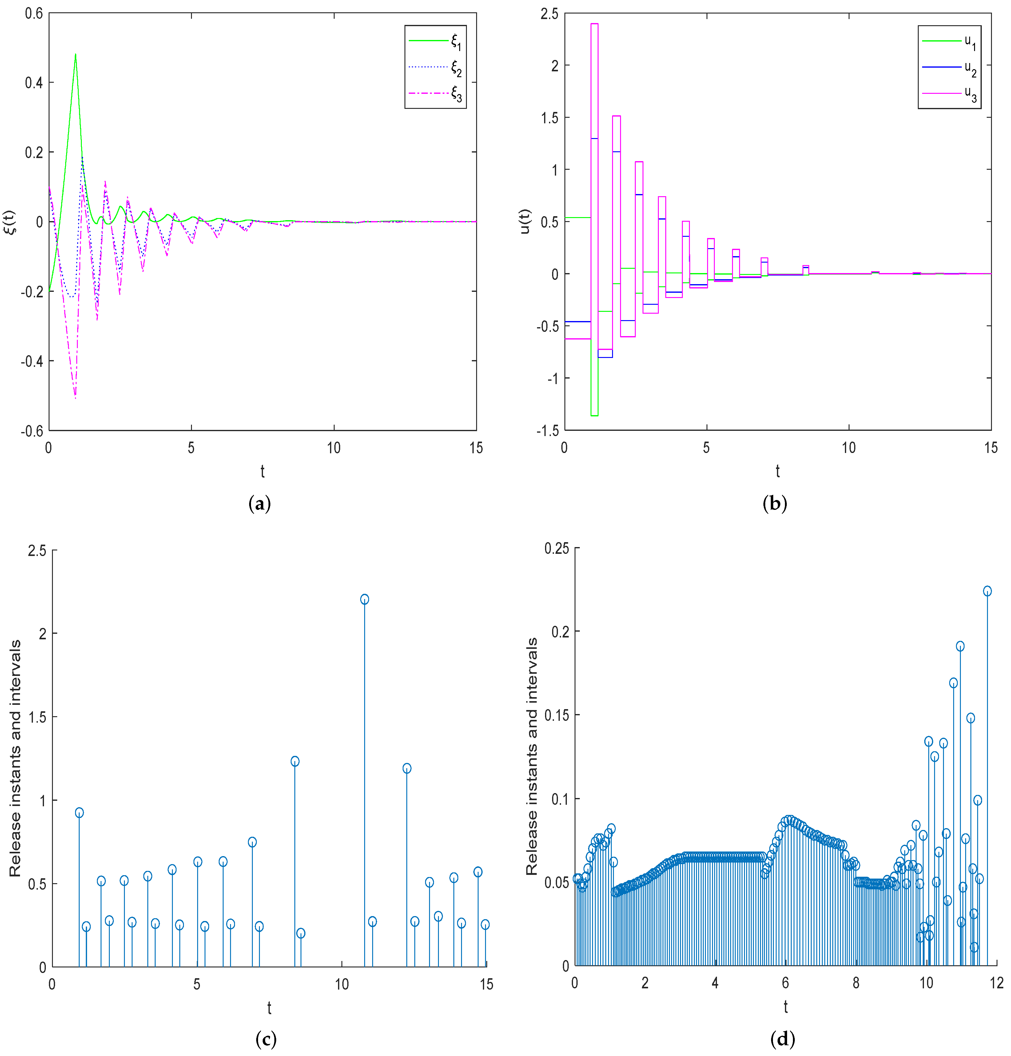
Based on the derived control gain and trigger matrix, the response states and control inputs of the error system are shown in Figure 2a,b, respectively. From Figure 2a, one can see that  ξ i ( t ) i = 1 , 2 , 3 , converges to the origin as times goes by. Also, Figure 2b displays the control inputs by using the corresponding RDET scheme (2). Clearly, the Lyapunov theory is applied to prove the effectiveness of the proposed method. That is,  | | ξ ( t ) | | p = 0 . That is to say, the synchronization behavior of the master–slave systems can be achieved based on the designed RDET scheme (2).
Next, Table 2 provides a comparison of triggering times between RDET (2) (based on Theorem 2) and DET (3) [10,11] (based on Corollary 2). Before solving Theorem 2 and Corollary 2, the initial parameters are chosen as  l 1 = 1 l 2 = 0.1 l 3 = 0.01 δ = 0.1 γ = 0.05 ι = 1 β = 1 h 1 = h 2 = 0.01 ϵ ( 0 ) = [ 0.4 0.3 0.8 ] T ζ ( 0 ) = [ 0.2 0.4 0.9 ] T . By using the above parameters, according to the previous DET scheme (3) [10,11], one can obtain  K = 2.3465 0.1556 0.2565 0.0664 3.4154 1.7852 0.2643 2.0624 3.4690 ,  and the  Ω  in Table 2 by solving LMIs (28)–(30) in Corollary 2. Figure 2c presents the sequence of triggering instants. Clearly, the total of the triggering times is 28 within 15 s. As shown in Figure 2d, the number of triggering times is 183. It shows the advantages of the RDET (2). The reason is that the introduced  α ( t ) = ι e β t  can enlarge the threshold function. Comparatively, the triggering times can be effectively decreased by employing the proposed RDET (2). It is clear that the proposed RDET (2) contributes to reducing the triggering times.

6. Conclusions

In this paper, the event-triggered synchronization issue is discussed for chaotic NNs by utilizing a refined trigger scheme. To decrease the communication burden, two discontinuous event-trigger schemes are applied to reduce trigger times. To analyze the stability, a useful lemma is established for the closed-loop systems. To derive synchronization results, a type of time-dependent functions is designed in the presence of trigger schemes. Based on inequality techniques and stability theory, some synchronization criteria are developed to guarantee that the synchronization behavior of a master–slave can be achieved.

Author Contributions

Writing—original draft preparation, Y.W.; supervision, Y.F.; funding acquisition, M.L. All authors have read and agreed to the published version of the manuscript.

Funding

This work was supported by the Shandong Provincial Natural Science Foundation ZR2024QG019.

Institutional Review Board Statement

Not applicable.

Informed Consent Statement

Not applicable.

Data Availability Statement

No new data were created or analyzed in this study.

Acknowledgments

We would like to express our great appreciation to the editors and reviewers.

Conflicts of Interest

The authors declare no conflicts of interest.

Abbreviations

The following abbreviations are used in this manuscript:
RDETrefined discontinuous event-trigger
TLFtime-dependent Lyapunov function
NNsneural networks
LMIlinear matrix inequality

References

  1. Huang, Q.; Ma, N.; Tu, Z.W. Lagrange stability of quaternion-valued memristive neural networks. Math. Methods Appl. Sci. 2024, 47, 14796–14806. [Google Scholar] [CrossRef]
  2. Hu, X.; Wang, L.M.; Sheng, Y.; Hu, J. Finite-time stabilization of fuzzy spatiotemporal competitive neural networks with hybrid time-varying delays. IEEE Trans. Fuzzy Syst. 2023, 31, 3015–3024. [Google Scholar] [CrossRef]
  3. Liu, H.W.; Chen, X.Y.; Qiu, J.L.; Zhao, F. Finite-time synchronization of complex networks with hybrid-coupled time-varying delay via event-triggered aperiodically intermittent pinning control. Math. Methods Appl. Sci. 2021. [Google Scholar] [CrossRef]
  4. Hu, B.; Guan, Z.H.; Xiong, N.; Chao, H.C. Intelligent impulsive synchronization of nonlinear interconnected neural networks for image protection. IEEE Trans. Ind. Inform. 2018, 14, 3775–3787. [Google Scholar] [CrossRef]
  5. Xu, X.Y.; Tan, M.X.; Corcoran, B.; Wu, J.; Boes, A.; Nguyen, T.G.; Chu, S.T.; Little, B.E.; Hicks, D.G.; Morandotti, R.; et al. 11 TOPS photonic convolutional accelerator for optical neural networks. Nature 2021, 589, 44–51. [Google Scholar] [CrossRef] [PubMed]
  6. Zhu, Y.; Wang, Z.; Liang, H.; Ahn, C.K. Neural-network-based predefined-time adaptive consensus in nonlinear multi-agent systems with switching topologies. IEEE Trans. Neural Netw. Learn. Syst. 2024, 35, 9995–10005. [Google Scholar] [CrossRef] [PubMed]
  7. Zhu, Y.; Xu, N.; Basin, M.V.; Zhou, D.; Chen, X. Stability and tracking recovery of continuous-time Markov jump piecewise affine systems using virtual-sensor-based reconfiguration. IEEE Trans. Autom. Control 2024, 69, 2705–2712. [Google Scholar] [CrossRef]
  8. Du, Z.B.; Kao, Y.G.; Zhao, X.D. An input delay approach to interval type-2 fuzzy exponential stabilization for nonlinear unreliable networked sampled-data control systems. IEEE Trans. Syst. Man Cybern. Syst. 2021, 51, 3488–3497. [Google Scholar] [CrossRef]
  9. Sun, Y.F.; Li, L.L.; Ho, D.W.C. Quantized synchronization control of networked nonlinear systems: Dynamic quantizer design with event-triggered mechanism. IEEE Trans. Cybern. 2023, 53, 184–196. [Google Scholar] [CrossRef] [PubMed]
  10. Liu, L.; Liu, Y.J.; Tong, S.C.; Gao, Z.W. Relative threshold-based event-triggered control for nonlinear constrained systems with application to aircraft wing rock motion. IEEE Trans. Ind. Inform. 2022, 18, 911–921. [Google Scholar] [CrossRef]
  11. Shi, S.; Fei, Z.Y.; Karimi, H.R.; Lam, H. Event-triggered control for switched T-S fuzzy systems with general asynchronism. IEEE Trans. Fuzzy Syst. 2022, 30, 27–38. [Google Scholar] [CrossRef]
  12. Yan, S.; Shen, M.; Nguang, S.K.; Zhang, G.; Zhang, L. A distributed delay method for event-triggered control of T-S fuzzy networked systems with transmission delay. IEEE Trans. Fuzzy Syst. 2019, 27, 1963–1973. [Google Scholar] [CrossRef]
  13. Cao, Y.T.; Wang, S.B.; Guo, Z.Y.; Huang, T.W.; Wen, S.P. Synchronization of memristive neural networks with leakage delay and parameters mismatch via event-triggered control. Neural Netw. 2019, 119, 178–189. [Google Scholar] [CrossRef] [PubMed]
  14. Sun, J.K.; Yang, J.; Li, S.H.; Zheng, W.X. Sampled-data-based event-triggered active disturbance rejection control for disturbed systems in networked environment. IEEE Trans. Cybern. 2019, 49, 556–566. [Google Scholar] [CrossRef] [PubMed]
  15. Song, X.; Zhang, Q.; Song, S.; Ahn, C.K. Sampled-data-based event-triggered fuzzy control for PDE systems under cyberattacks. IEEE Trans. Fuzzy Syst. 2022, 30, 2693–2705. [Google Scholar] [CrossRef]
  16. Fei, Z.Y.; Guan, C.X.; Gao, H.J. Exponential synchronization of networked chaotic delayed neural network by a hybrid event trigger scheme. IEEE Trans. Neural Netw. Learn. Syst. 2018, 29, 2558–2567. [Google Scholar] [CrossRef] [PubMed]
  17. Lee, T.H.; Park, J.H. Stability analysis of sampled-data systems via free-matrix-based time-dependent discontinuous Lyapunov approach. IEEE Trans. Autom. Control 2017, 62, 3653–3657. [Google Scholar] [CrossRef]
  18. Xu, X.Z.; Li, Y.; Zhang, H.B.; Chen, W.; Zheng, Q.X. Practical stability for switched affine systems via time-dependent switching function. Int. J. Robust Nonlinear Control 2021, 31, 9731–9744. [Google Scholar] [CrossRef]
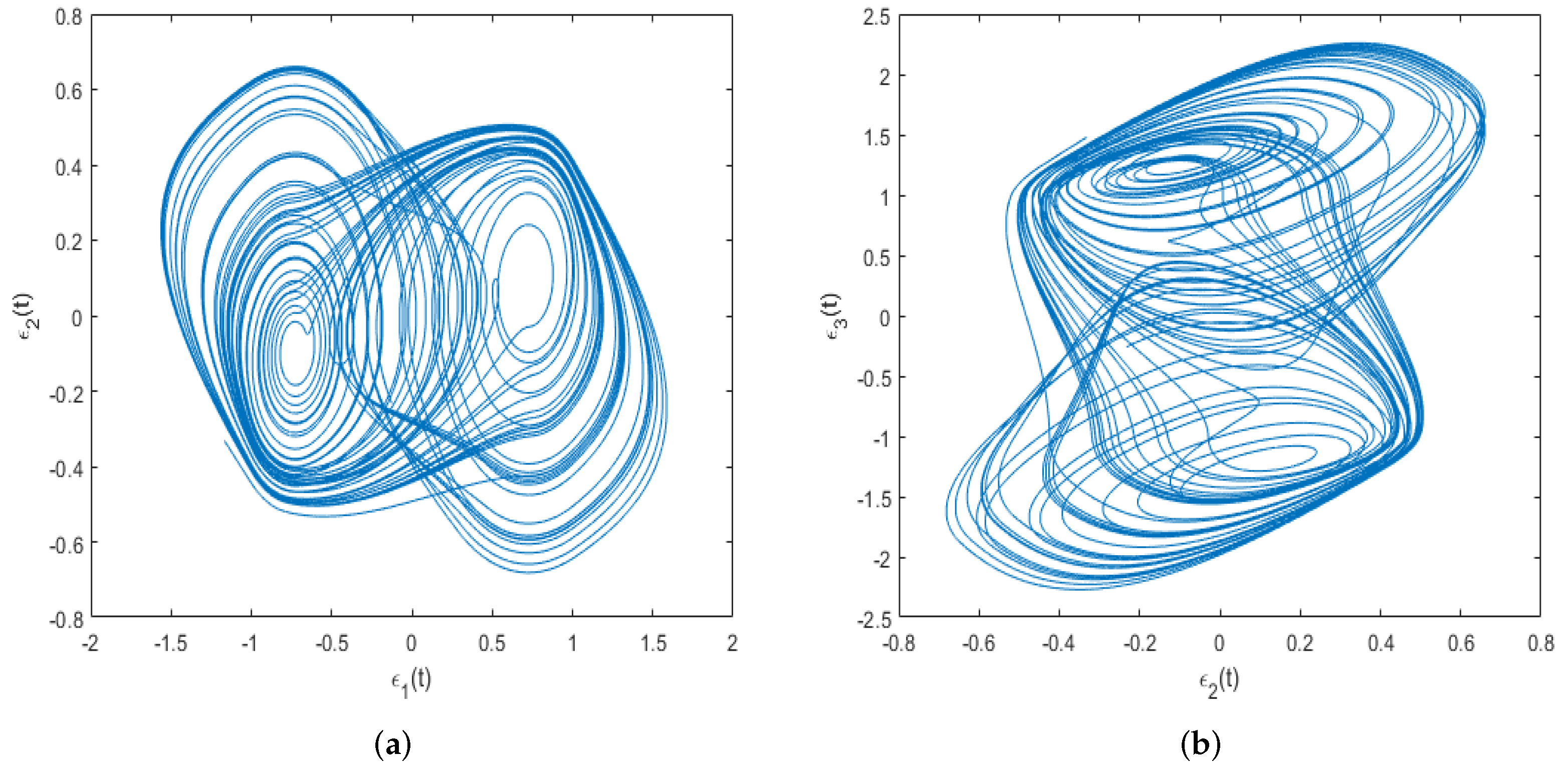
Figure 1. Chaotic attractors with  ϵ ( 0 ) = [ 0.4 0.3 0.8 ] T  on (a):  ϵ 1 ϵ 2 ; (b):  ϵ 2 ϵ 3 .
Axioms 14 00403 g001
Figure 2. (a) Responses of  ξ i i = 1 , 2 , 3 ; (b) control inputs; (c,d) triggering times based on RDET scheme (2) and DET scheme (3) in [10,11], respectively.
Axioms 14 00403 g002
Table 1. Notations and descriptions.
NotationDescription
  λ max ( Q ) the maximum eigenvalue of matrix Q
  Q T ( or Q 1 ) transpose (or inverse) of matrix Q
*the symmetric element
  Q > 0 Q is a positive
(or  Q 0 ) definite (or semi-definite) matrix
diag ( ) a block diagonal matrix
Table 2. Comparisons of triggering times between RDET (2) (based on Theorem 2) and DET (3) [10,11] (based on Corollary 2).
Scheme   Ω Triggering Time
[10,11] 0.8925 0.0746 0.0721 0.0746 2.0886 1.4898 0.0721 1.4898 1.8672 183
RDET (2) 0.3715 0.0304 0.0197 0.0304 0.6021 0.2747 0.0197 0.2747 0.4960 28
Disclaimer/Publisher’s Note: The statements, opinions and data contained in all publications are solely those of the individual author(s) and contributor(s) and not of MDPI and/or the editor(s). MDPI and/or the editor(s) disclaim responsibility for any injury to people or property resulting from any ideas, methods, instructions or products referred to in the content.