1. Introduction
Polyhedral cages (p-cages) are a rather natural generalisation of the polyhedron surface. Both polyhedron surfaces and p-cages are three-dimensional objects consisting of planar polygons (faces) joined together at shared edges. P-cages, however, unlike polyhedrons, are allowed to have holes; i.e., not all the edges are shared by two polygons, and some only belong to one face and neighbour holes (hole-edges). Furthermore, it is prescribed that, along the boundary of any given face, shared edges cannot be adjacent to one another.
P-cages are not interesting merely for their naturalness of the concept. They were recently introduced because of their applicability to model the geometry of artificial protein cages [
1,
2,
3,
4]. These cages are artificially synthesised from protein molecules with metal ions at the shared edges, and the first cage was composed of the TRAP protein, with hendecagonal faces.
The TRAP cage was experimentally found to have an 11-fold rotational symmetry, an apparent contradiction to Johnson and Grünbaum’s theorem [
5]. The resolution of this apparent paradox was the fact that the symmetry is only approximate, leading to the definition of near-miss regular p-cages. Regular p-cages are those whose faces are regular polygons. Near miss regular p-cages are those for which all the faces have small deviations from regularity. Following [
6,
7,
8], we will restrict ourselves to deformations not exceeding 10%.
Apart from the TRAP cage with 11-fold symmetry, a number of artificial protein cages have been realised experimentally, with growing control over the type of cage formed [
9,
10,
11,
12,
13,
14,
15]. Joining proteins for artificial cages is not easy and requires suitable geometries and binding properties between them [
16,
17,
18,
19]. Some protein cages are built using symmetry properties [
20,
21,
22], while others break known symmetries [
23].
One of the principal goals of the research into protein cages is targeted drug delivery [
24,
25,
26,
27,
28] by enclosing drug molecules in protein cages while adding some molecular parts to the outside of the cage such that they interact with receptors on the membranes on the targeted cells only, and building the cages in such a way that they open once inside the cytoplasm of the targeted cells, releasing the drugs [
4,
29,
30,
31,
32]. The opening of the p-cage inside the cytoplasm can be spontaneous or magnetically induced [
33]. It is projected that, in this way, some side effects of certain therapies may be greatly alleviated. The need to catalogue the possible geometries arises naturally [
34,
35,
36]. In addition to their applicability in the bio-nanosciences, p-cages, in regular and near-miss cases, have rather appealing aesthetic structures [
2], which might suggest applications in the arts.
Large catalogues of near-miss regular p-cages have been constructed, either with no additional assumptions on the equivalence of the faces [
6] or with the assumption that either all the faces are identical [
7] or all the faces fall into one or the other of two families, within which all the faces are equivalent [
8,
37].
The studies cited above focused on either specific p-cages relevant to experiments performed or cataloguing p-cages with symmetries. The goal of the present paper is to examine how typical p-cages look, what p-cages are possible if there is a large extent of randomness in the formation process, and how far these typical p-cages are from regularity.
We remark that our methods do not involve the simulation of p-cage formation. On one hand, due to the size of the protein molecules involved, molecular dynamics is not feasible. On the other hand, we would also like to understand the question of typical random p-cages at the level of p-cage geometry. To this end, we shall build p-cages by adding polygons one by one in such a way that at each step we choose the number of vertices of the polygon and/or its position randomly and then add random connections between the polygons and examine the p-cages formed in this way.
Once the planar faces of a p-cage are joined together at some of their edges to displace or modify a face of the p-cage, one must modify at least one adjacent face simultaneously. Algorithmically, this is difficult to perform efficiently, so, instead, we start by linking the faces with virtual short springs so that any change to a specific face only affects the stretching of the springs attached to that face. The energy (cost) of these springs is proportional to the square of the elongation of the string relative to its natural length as well as the angle they form with the joined faces. By minimising these energies, one obtains a structure that is closer to an actual p-cage. This method enables us to preselect configurations likely to lead to p-cages with deformations that are not excessively large. To obtain a p-cage, we replace the connected vertices with a single vertex and optimise the full p-cage structure from scratch, including all the planarity and convexity constraints. This two-stage method is quite flexible and efficient; it was already implemented in a slightly different context in [
6].
2. Near-Miss p-Cages
A p-cage [
1,
2,
3,
6], by definition, is a surface in three-dimensional Euclidean space consisting of polygons joined together at edges. Edges shared by two polygons are termed shared edges and those belonging only to one polygon are hole-edges. To avoid pathological cases, it is assumed that two polygons in the p-cage may share one or zero edges. For the structure to have some rigidity properties, it is assumed that each face has at least three neighbours, i.e., faces with which it shares an edge. In order that p-cages are visibly cage-like, it is also prescribed that, along the edge of any face, no two shared edges are adjacent.
P-cages are homogeneous or bi-homogeneous if they are, respectively, composed of a single type or two types of polygons. Similarly, p-cages are symmetric or bi-symmetric if their faces belong, respectively, to a single or two families such that all faces of a given family can be mapped into each other via a rotation of the p-cage.
In [
6,
7], we consider a p-cage to be convex if all its faces are convex polygons and if its holes can be closed with a surface in such a way that the resulting surface is the boundary of a convex body. In this paper, we adopt a different definition, mostly motivated from computational purposes, i.e., that a p-cage is convex if all its faces are convex polygons and if the internal angles between pairs of adjacent faces are convex, i.e., less than
. As we shall see later in an example, this definition is more general than the former one.
To each p-cage, a connectivity structure can be associated. Firstly, placing a vertex at the centre of each face and connecting such face centres if faces share an edge yields a polyhedron in three-dimensional space that is termed the dual polyhedron of the p-cage [
6]. Any polyhedron can be mapped onto a planar graph, which is the hole-polyhedron graph of the p-cage. At all vertices of this graph, around the vertex one may add labels between each edge denoting the number of hole-edges between the two shared edges corresponding to the edge in the hole-polyhedron graph. The hole-polyhedron graph together with the labels determine the connectivity structure of the graph. All previous work providing catalogues of some p-cages [
6,
7,
8,
37] classify their p-cages by their connectivity structure. Note, e.g., that, for symmetric homogeneous p-cages, i.e., p-cages where there is a rotation in space mapping a given face of the p-cage onto any other face, the hole polyhedron is a Platonic or Archimedean solid [
6,
7], and the full symmetry group is a subset of the three-dimensional rotation group. In the case of bi-symmetric p-cages, a list of possible hole-polyhedron graphs was provided in [
38].
The Euler characteristic
C of a structure is defined as [
39]
where
V represents the number of vertices,
E the number of edges, and
F the number of faces. The Euler characteristic of a polyhedron is always 2. This implies that the Euler characteristic of a p-cage is
where
H is the number of holes of the p-cage. To prove this, we first notice that the vertices of the p-cages are attached to 2 edges if they are shared between 2 faces, and to only 2 edges if they belong to a single face. If a p-cage is such that all its vertices are shared between 2 faces, then the holes can be viewed as faces that have been removed; in that case,
. If we add a vertex in the middle of a hole-edge, we also increase the number of edges by one so that
V and
E both increase by 1, and, by (
1),
C remains unchanged, proving that
for all p-cages.
A p-cage is regular if all its faces are regular polyhedra. The TRAP p-cage discovered by the Heddle group looked like a regular p-cage in all observations; however, its apparent symmetry group contained an 11-fold rotation, apparently in contradiction to Grünbaum and Johnson’s theorem. The resolution of this “paradox” is that the p-cage is not exactly regular. This led to the introduction of near-miss p-cages [
1,
6]. A near-miss p-cage is one for which each face differs from a regular polygon by a small deformation. To quantify deformation, we calculate for each face
f and vertex
v on that face the deviation of the length
of the edge after that vertex (e.g., in a clockwise ordering) from a target length
L,
and similarly for angles,
where
is the angle at vertex
v on face
f and
is the number of vertices on face
f.
To generate p-cages randomly, we will generate approximate structures composed of nearly regular planar polygons linked together at some of their edges. To obtain p-cage composed of faces that are nearly regular, we will introduce an energy function measuring the amount of deformation, which we will then minimize numerically using a simulated annealing algorithm to optimise the configuration, i.e., minimize the irregularity of the faces.
When building p-cages, an energy (or “cost”) function is introduced that depends on the squared deviations of the edge lengths and angles, supplemented with constraint terms for, e.g., convexity, and that is optimised, with the optimisation parameters, e.g., the relative weights of angle and length deformation terms, being varied to minimise the maximal deviations [
6,
7,
8,
37]. The two main terms in the cost functions are angle deformation and length deformation energies,
where the angle deformation on face
f at vertex
v is defined as
where
is the angle at vertex
v on face
f, and the length deformation energy on edge
e of face
v is
where
is the length of vertex
e on face
f. The two coefficients
and
are termed angle deformation and length deformation coefficient, and, to balance
and
, they are varied but constrained to satisfy
. For details of these terms, see
Appendix A.
In the laboratory, protein cages are built using chemical reactions. First, the so-called rings or polygons are composed of multiple copies of the same protein [
1]. Then, these polygons are put in a solution so as to bind together and form a p-cage. This assembly of the polygons to form p-cages is random. It is an almost obvious question to ask what kinds of p-cages can form randomly and what their typical deviations are from regularity. A full-featured molecular dynamics simulation would be computationally extremely demanding; therefore, we perform a rather simplified procedure here to create random p-cages.
As stated above, in their full configurations, it is not possible to modify a p-cage face without affecting some of the faces to which it is attached. In order that this does not limit the intermediate steps of p-cage formation, we shall first introduce a simplified intermediate object, which can more easily be formed randomly, and an algorithm to form those. The simplified structure is the spring-connected set of polygons, for which conversion is, as we shall see, quite easy.
3. Spring-Connected Sets of Polygons
A spring-connected set of polygons (polyset for short) is a number of regular planar polygons in three-dimensional Euclidean space together with a number of line segments connecting vertices of polygons termed springs or spring connections.
The conditions on the number and placement of the springs shall be such that polysets can be thought of as p-cages with shared edges replaced by two edges and springs connecting the vertices at the ends of all pairs of edges replacing the shared edges: (i) spring connections are in pairs such that the ends of the two springs in a pair are on adjacent edges of two faces connected; (ii) the neighbourhood relations of the polyset are the same as the corresponding p-cage.
To make this more explicit, we introduce the definition of shared edges as edges in a polyset such that on both ends of the edge there is a spring connection. We demand that, along the edge of each polygon in a polyset, shared edges are never adjacent, and that both ends of a shared edge are connected to the same neighbouring polygon, to the ends of the same shared edge on the other face. We prescribe that each face shall have at least three neighbours (i.e., faces to which it is connected) and that two polygons are connected at the ends of one or zero of their shared edges.
As in a polyset, all polygons are regular; the deformations that enable the connection of them are now located in the spring connections. We introduce
to denote the length of a spring-connecting vertex
of face
to vertex
of face
, the tensionless length
of a spring, and the elastic energy
where
is the spring constant,
is a coefficient for the quartic term (usually set to 0 or very small), and
is a deformation; the aim of the quartic term is to disallow deformations from
much larger than
. The total energy is obtained by summing over all faces
where there is a spring connection between the vertices
and
on the respective faces,
Similarly, a link-bending energy term is introduced to prescribe the angle between the normals of two adjacent faces as
and
.
Also, at all links, a bending term is added, which is
where the summation now is over all pairs of springs at two ends of a pair of edges. The angle
is calculated as the angle of the normals of the two faces.
To avoid large energies in the p-cage after conversion to a p-cage, we also add an energy term to disallow twisting of links,
which is summed over pairs of links between faces
and
, linking two neighbouring pairs of vertices
and
with
and
on the respective faces. An upper index 0 over a vector denotes the unit vector in the direction of that vector.
In addition to the energy terms in Equations (
8) and (
10), a number of additional constraints are used, enforcing a maximal link length, maximal angle between neighbouring faces, which the normals of the faces point to the outside (to disallow flipped faces), and a convexity constraint to cap the angle between adjacent faces.
Further terms, such as Coulomb repulsion between charges at the centres of the faces, etc., may be added and turned on. For further details, we refer to
Appendix B and the deposited code.
4. Polyset Formation Algorithm and Conversion to p-Cage
The p-cage is a very rigid structure, which is manifested, e.g., in the fact that a catalogue of p-cages of a reasonable size with deviation from regularity below some limits can be constructed [
6,
7,
8,
37]. Although a simulation of p-cage formation using molecular dynamics is not feasible, we are interested in a simplified procedure that yields p-cages that could form in some noisy procedure. In what follows, we outline such an algorithm.
To loosen the rigidity of the p-cage structure to make intermediate steps of the algorithm possible, we first provide an algorithm to build random polysets and, in the last step, convert polysets to p-cages.
Our polyset-building algorithm is as follows. We start with a list of regular polygons with edge length set to the target length, and vertex numbers , …, , and a set of probabilities, , …, , . Initially, we start with a -gon.
We shall repeat adding faces as long as a target number is not reached or until a preset number of attempts is exhausted.
In each step, we choose an edge to add a face. We implemented two variants of the algorithm; in one of them, we keep track of the “outside” of the already added polygons, and new polygons are attached to an edge on the outside. The outside is for the initial face the edge thereof, and, later, as polygons are added, at each step, the edge where the new face is added is replaced by the boundary of the new face without the new shared edge thereon. In the other variant, the edge is chosen in the largest hole of the already existing polyset. When choosing the edge, we make sure that the prescriptions of the polyset (e.g., no two shared edges are adjacent along the boundary of any face) remain valid. Once an edge is chosen, the polygon is placed in the vicinity of that edge and connected to it.
After adding a face, we try to connect it to other edges on the boundary or the same large hole. Again, in each step, an edge is chosen randomly in such a way that the connectivity prescriptions of a polyset are not violated. An attempt is made to connect the edge if the energy cost of adding the two springs is not too large (made negative by the binding energy or accepted with a Boltzmann probability with a preset connection temperature). After each new connection, the outside of the already formed polyset is updated in the corresponding version of the algorithm (which is not required in the other version; holes can simply be recalculated). This step is repeated a prescribed number of times.
Once the new face is added and connected, the energy of the polyset is optimised. If the energy of the polyset grows by more than a preset threshold value, the new face is removed and the polygon positions reset to their values before this attempt of adding a face. Optionally, it is also verified that the resulting polyset is not self-intersecting, and, if this is violated again, the step is undone.
Once the desired number of faces are achieved or the attempts exhausted, the polyset is pruned; i.e., all faces having less than three neighbours are removed. This step is iterated until no more faces have less than three neighbours.
Once polysets are formed, to convert them into p-cages, we replace the two vertices connected by a spring with the midpoint of the spring for all spring connections in the polyset and optimise the resulting p-cage, at least until the faces become planar again.
The optimisation algorithm used is our reimplementation of the method used in [
40]. Their source file on Netlib has been consulted.
5. Results
In this section, we provide examples of p-cages generated with our algorithm using a simulated annealing method. Our approach is as follows: we either select for the faces polygons of a specific type or we pick them randomly from a predecided set of two or three different types of polygons, with, most of the time, identical probabilities. Faces were added one by one randomly to the polyset structure until it formed a nearly closed structure. The obtained structures were then converted to a p-cage as described above and then optimised using a simulated annealing method. Of the generated p-cages, we provide examples chosen for their aesthetic nature. A larger list of p-cages is deposited in data format as
Supplementary Material. We also provide the code separately in a data repository.
5.1. Cages Built with One Type of Polygon
We have run the code, building random p-cages with all polygons from hexagons to pentadecagons. In what follows, we summarise the results and show a few p-cages. For the data of the p-cages built and figures of the one not shown here, see the
Supplementary Materials and the data repository.
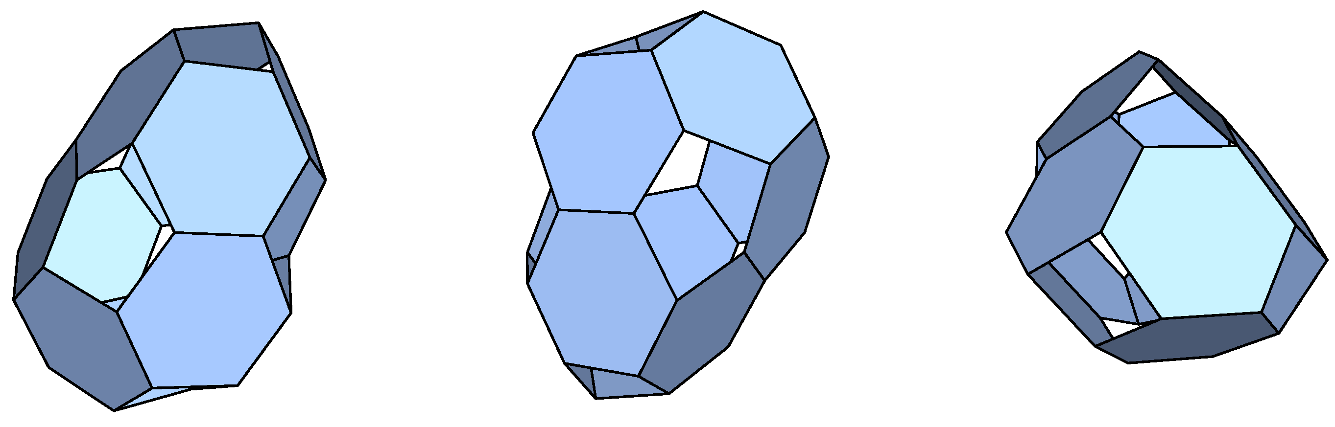
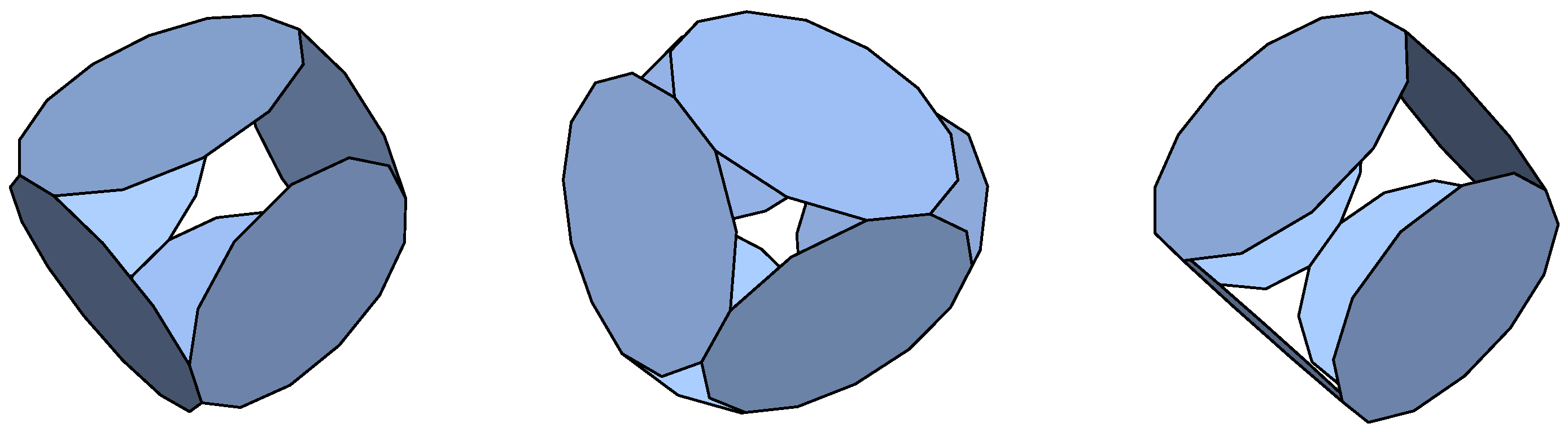
Hexagons: Below a 10% deformation limit, we have recovered the cube, pentagonal, and hexagonal prisms regarding the homogeneous p-cages already considered in [
6,
7]. An additional rather aesthetic p-cage was found that is shown in
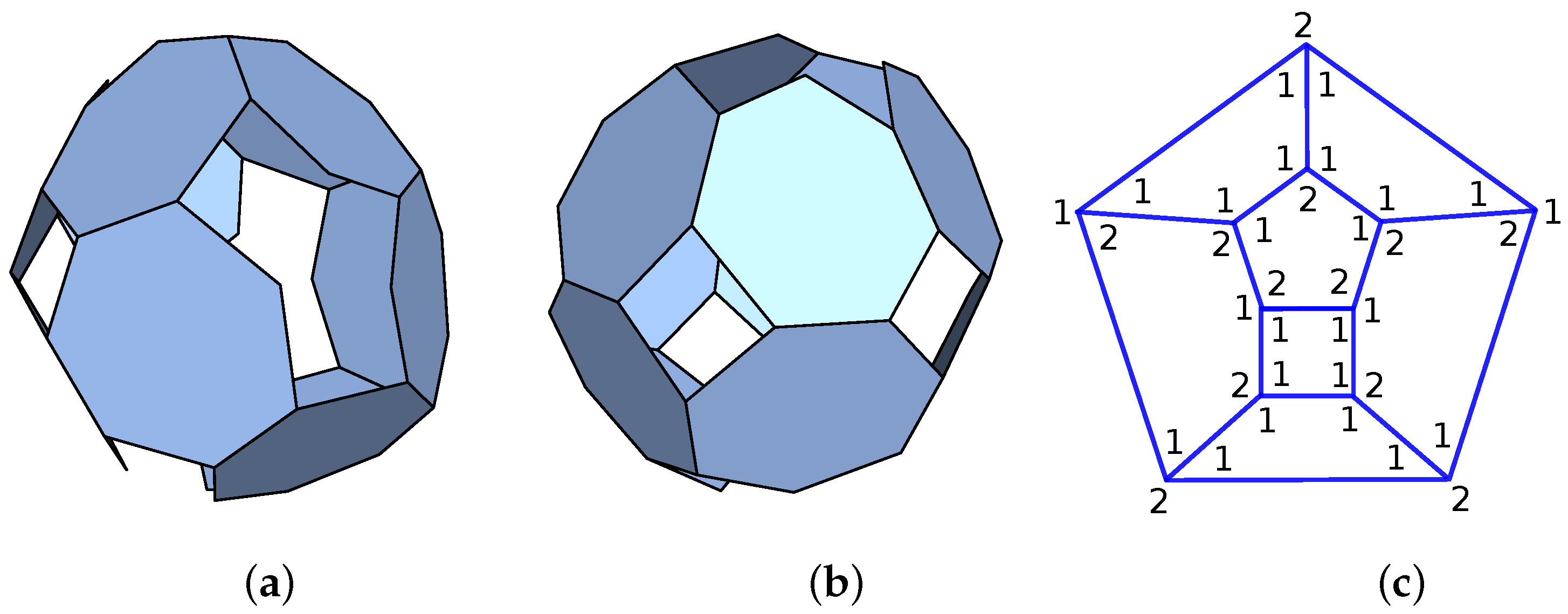
Figure 1. The connectivity structure (hole-polyhedron graph) of the p-cage is shown in
Figure 2. Notice that this p-cage is convex according to the definition we have adopted in this paper but not for the one adopted in [
6,
7].
Heptagons: We did not find any p-cages with a deformation below our 10% deformation limit, but we show in
Figure 2a p-cage that has the same hole-polyhedron graph as the regular p-cage composed of hexagons and shown in
Figure 1.
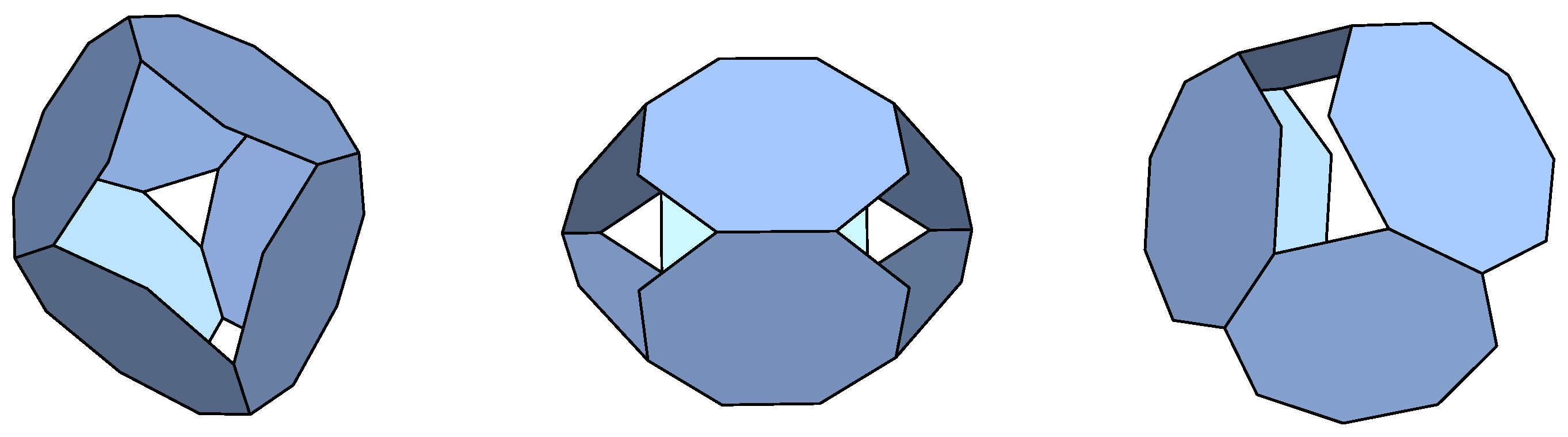
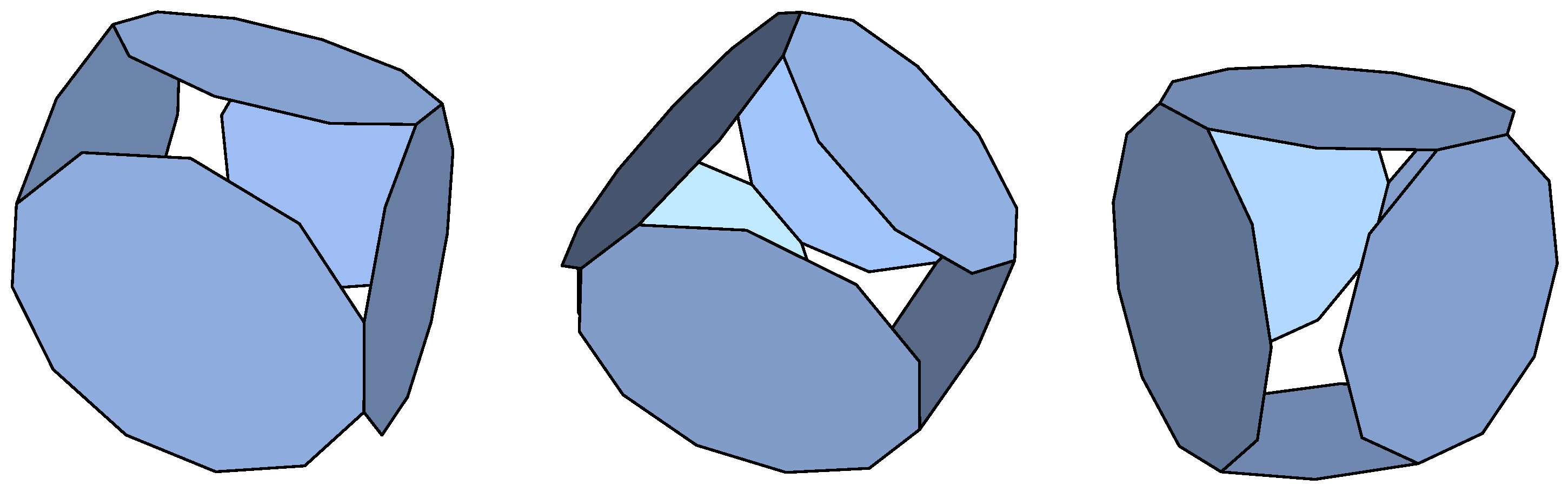
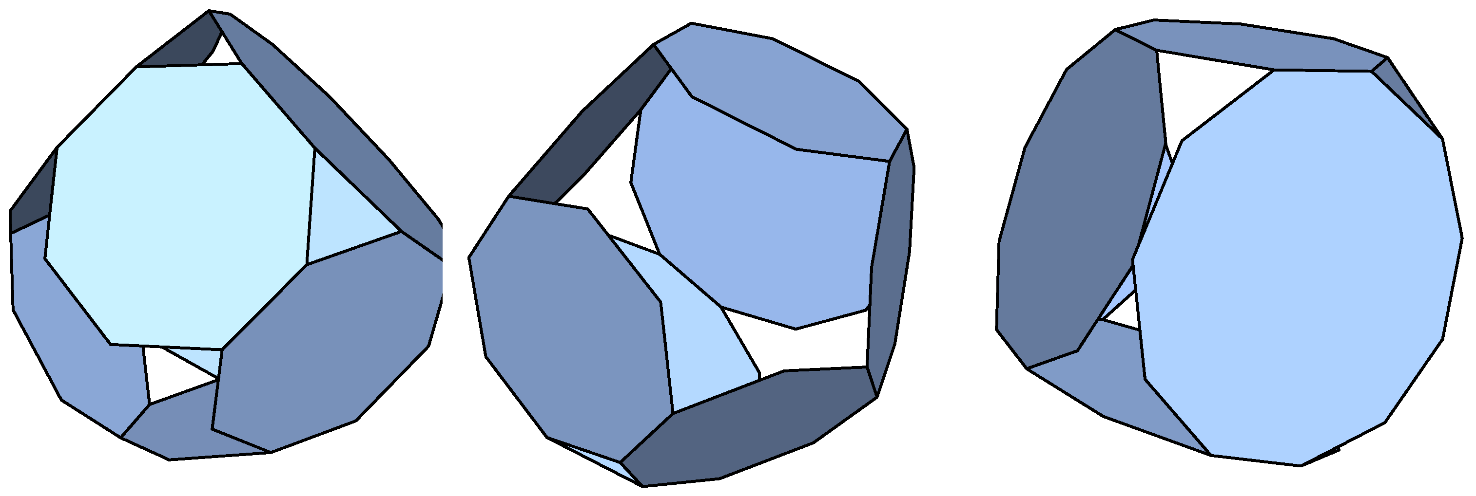
Octagons: Our algorithm reconstructed the truncated cube [
6,
7]. Two additional p-cages below the deformation limit of 10% were obtained. One of them is shown in
Figure 3.
Nonagons: Our algorithm reconstructed the square anti-prism homogeneous p-cage. Four additional non-symmetric near-miss p-cages were found, which, however, have large holes.
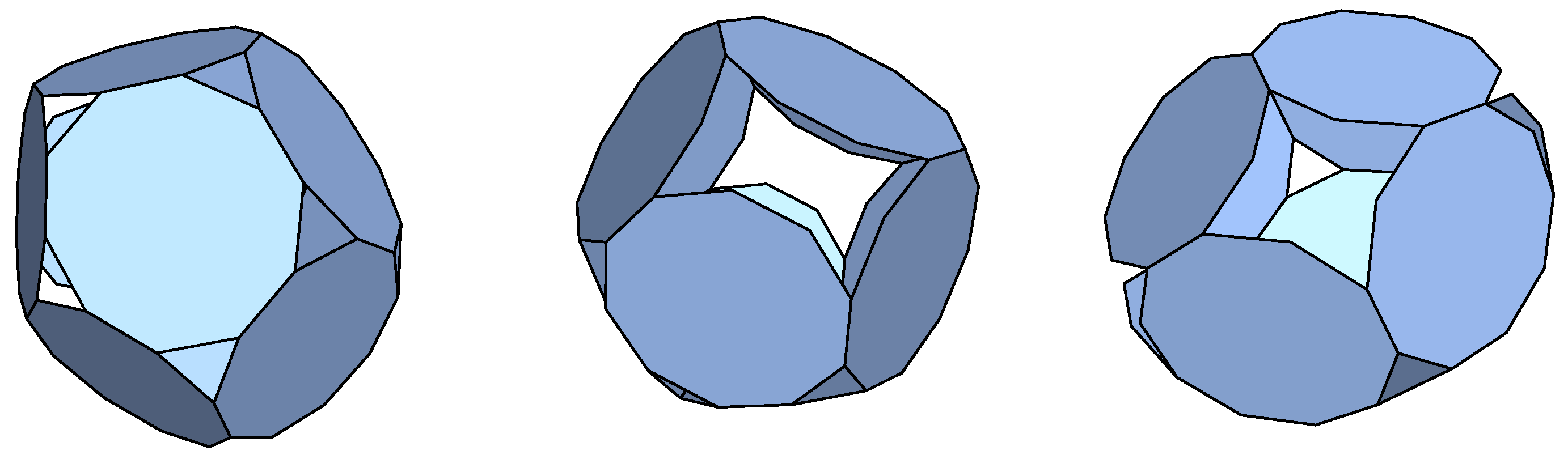
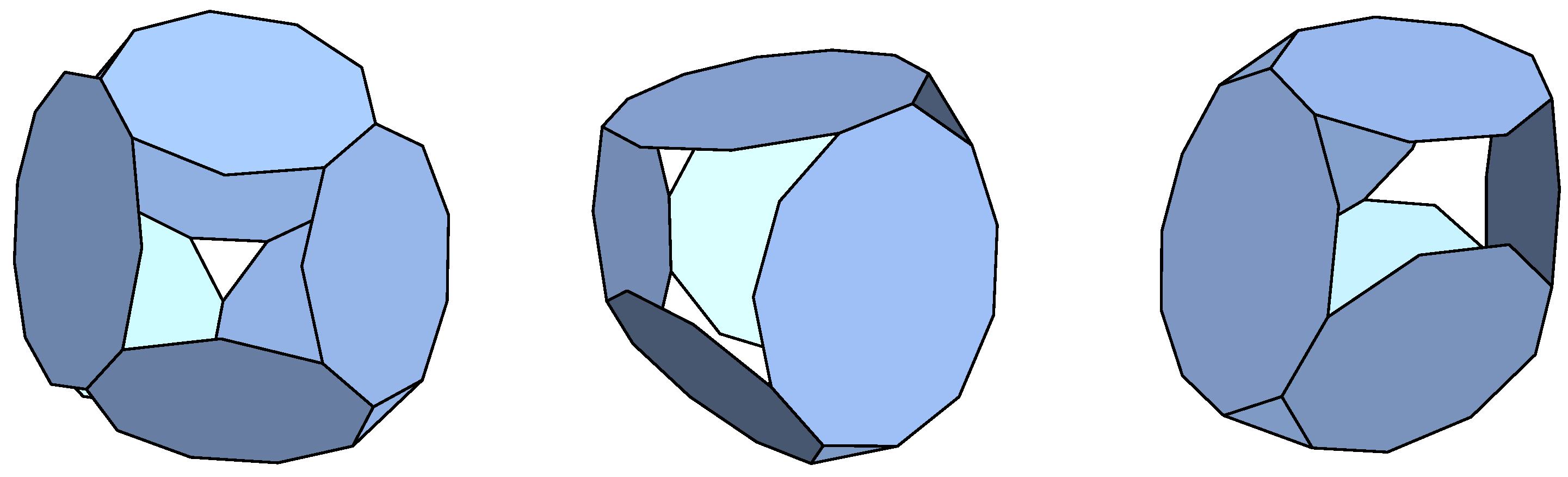
Decagons: We have found three non-symmetric p-cages. One of them is shown in
Figure 4.
Hendecagons: Although the most well-known p-cage is the TRAP cage built from hendecagons, due to the rapidly growing number of possible connection structures, random p-cage formation has not reproduced it. We found one additional near-miss p-cage.
Dodecagons: We obtained two non-regular p-cages.
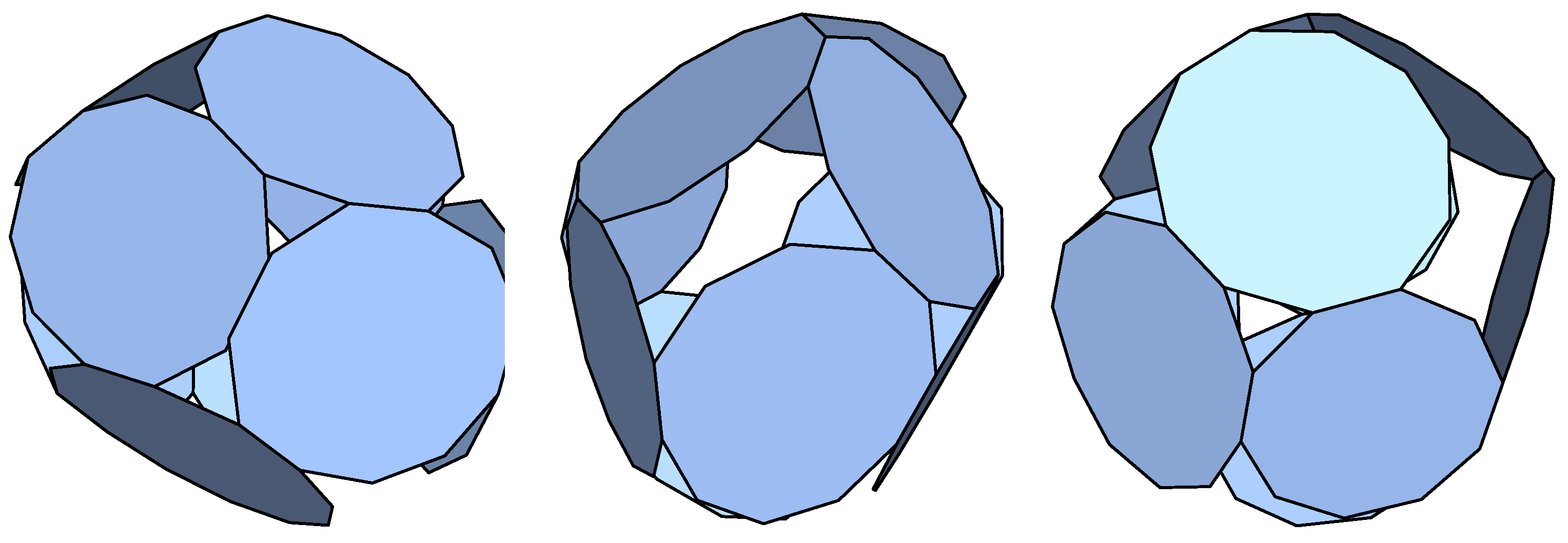
Tridecagons: We obtained six non-regular p-cages. One of them is shown in
Figure 5.
Tetradecagons: We obtained two non-regular p-cages.
Pentadecagons: We obtained two non-regular p-cages.
5.2. P-Cages Built with Two Types of Polygons
We have also run the code with hendecagons and another polygon type chosen to have between six and ten edges. The near-miss p-cages obtained are shown in
Table 1. Very few of the p-cages that we have obtained were equivalent or bi-equivalent p-cages. Most of those we obtained were composed of six faces with a hole-polyhedron graph being that of a triangular prism or a cube. The p-cages that we obtained are all described in the
Supplementary Materials. In
Figure 6, we present a p-cage composed of three decagons and three hendecagons; it has the lowest deformation of all the p-cages composed of two polyhedra that we have obtained in this category. In
Figure 7, we present a p-cage composed of four nonagons and three hendecagons.
5.3. P-Cages Built with Three Types of Polygons
We have run our code with hendecagons, decagons, and one of hexagons, octagons, and dodecagons. Many of them have as their edge hole graph the planar graph of a regular polyhedron such as a prism or a cube. The near-miss p-cages with deformations below 10% that have been obtained are listed in
Table 1. Most of the p-cages generated are composed of six or seven faces with a few with eight faces and one with nine faces, shown in
Figure 8. They are all described in the
Supplementary Materials.
Another example of a p-cage built out of three types of polygons is shown in
Figure 9. Its hole-edge graph is not that of a regular solid.
The p-cages with non-equivalent faces are summarised in
Table 1.
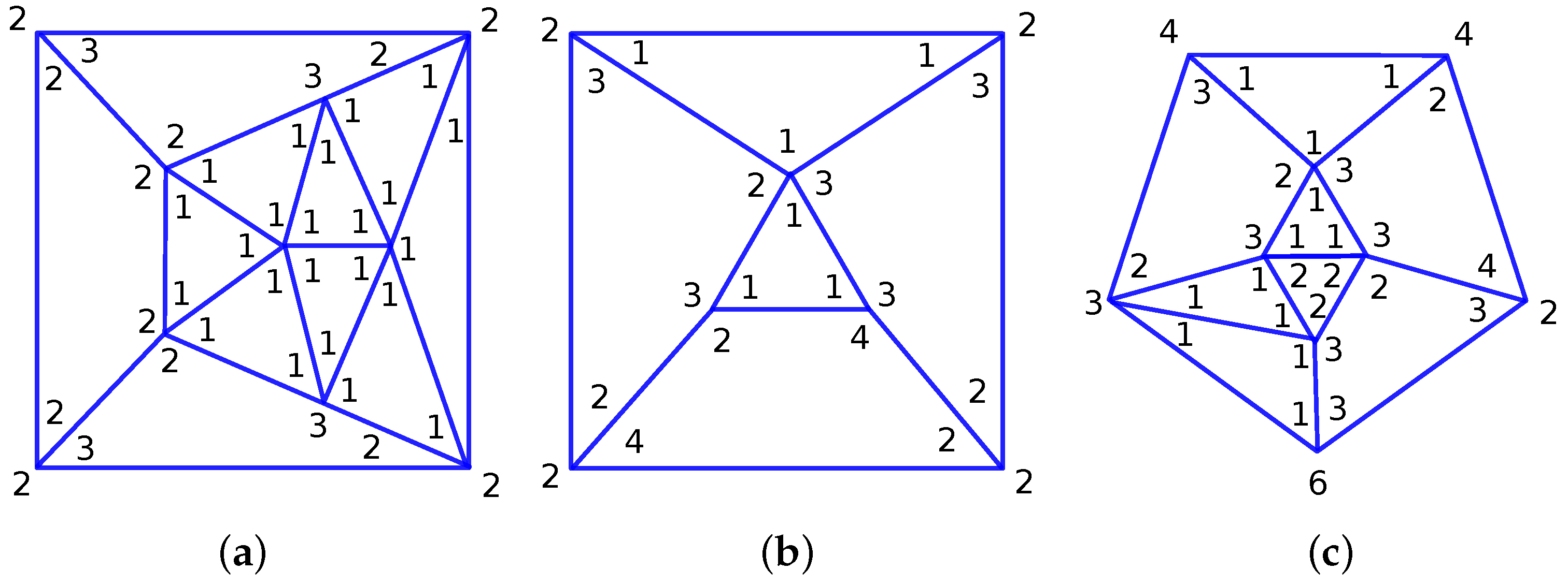
5.4. Hole-Polyhedron Graph
The hole-polyhedron graphs describe the connectivity of the p-cages. The nodes of the graphs correspond to the faces of the p-cage. The edges of the graphs describe how the different faces are attached to each other (share an edge). The faces of the graph then describe the structure of the holes. We also write in the corners of the face the number of hole-edges contributed to the hole by the corresponding face. If we add together the number adjacent to a specific node and the number of edges attached to that node, we obtain the number of edges of the polygon corresponding to that node. For example, one, two, one, and three add up to seven, which, after adding four as the number of edges, provides eleven, indicating that node corresponds to a hendecagon.
The number of edges of the face corresponding to a given node is obtained by adding together the number of hole-edges around a node to the number of links to neighbour nodes.
The hole-edge polyhedron for the p-cage composed of one type of polygon is shown in
Figure 2c. The number of hole-edges shown in
Figure 2c corresponds to the p-cage composed of 10 decagons. For the regular p-cage composed of hexagons, the hole-edge numbers are all one.
6. Conclusions
In the research summarised in the present paper, we implemented a random process that is a simple model of the formation of polyhedral p-cages out of polygons. As the p-cage structure is very rigid, to enable more variation, we formed an intermediate product, a set of polygons connected by elastic links (springs).
As the definition of a p-cage demands that all the faces have at least three neighbours, and, along the edges of each of the faces, no two subsequent edges may be shared with another face, the smallest polygon that can be the face of a p-cage is a hexagon, and, in the case of p-cages formed out of hexagons, all the combinatorial variations are in the choice regarding the faces between which each link is placed. For larger polygons, the number of possibilities for the connection structure is vastly larger as there is additional variability in the number of hole-edges between the pairs of shared edges along the edges of the faces. Consequently, only for small faces is it possible to reconstruct the homogeneous p-cages considered in [
6,
7].
In addition to reconstructing some of the already known homogeneous p-cages, the random formation procedure, run on the Department’s Condor computer cluster, produced a number of p-cages composed of one, two, or three types of polygons with angle and edge length deformations below 10%. The numerical procedure we adopted will never provide a full list of non-symmetric p-cages, but it does provide a number of such p-cages and did generate a regular p-cage, the faces of which are neither symmetric nor bi-symmetric.
For p-cages composed of polygons of a single type, most of the obtained ones are of the symmetric type, i.e., those for which all the faces are equivalent under a rotation of the p-cage. While we cannot claim to have modelled the random formation of an artificial p-cage, this suggests that symmetric p-cages are more likely to form in this case.
When p-cages are composed of two types of faces, most of them have non-equivalent faces but still have as hole-polyhedron graphs the planar graphs of a regular solid (mostly prisms, cubes, or octagons). This suggests that the bi-equivalent p-cages described in [
8,
37] are unlikely to form spontaneously unless the links between the faces are such that only a small amount of deformation from regularity is possible. All the random p-cages that we observed exhibit relatively large deformations.
P-cages composed of three types of faces do not exhibit equivalence among their faces but still largely correspond, as hole-polyhedron graphs, to the planar graphs of regular solids. They also exhibit relatively large deformations.


