Fabrication of Si Nanoparticles@Carbon Fibers Composites from Natural Nanoclay as an Advanced Lithium-Ion Battery Flexible Anode

 ,
, 
Abstract
1. Introduction
2. Materials and Methods
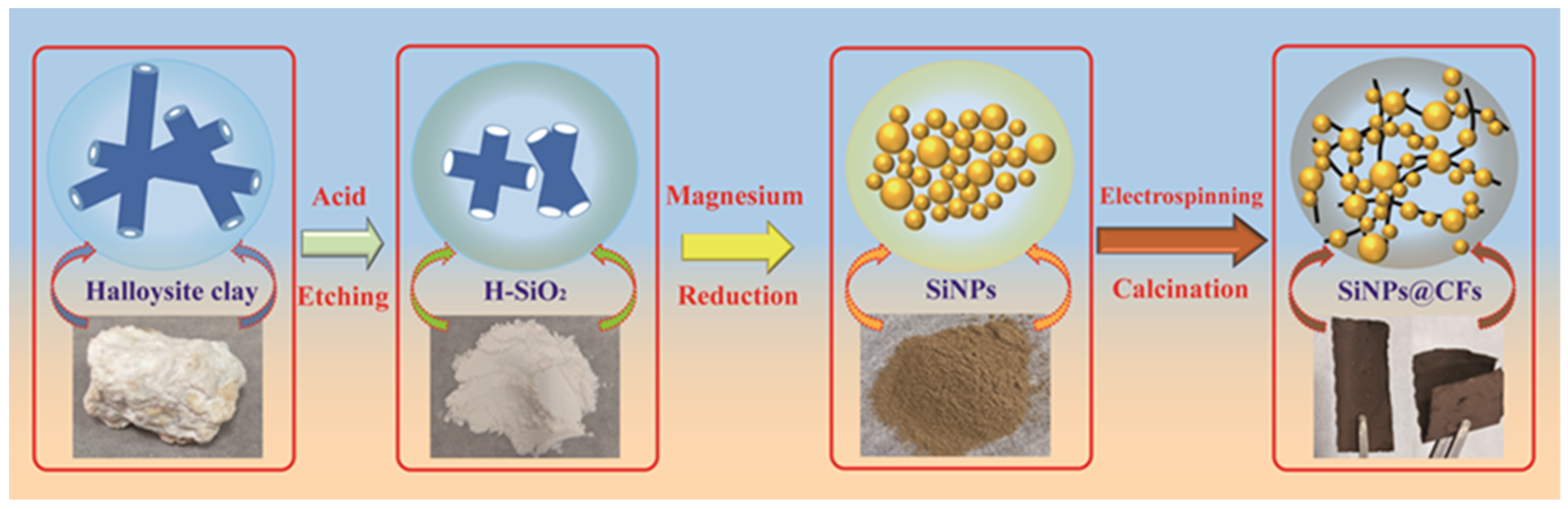
2.1. Material Synthesis
2.2. Materials Characterization
2.3. Electrochemical Characterization
3. Results
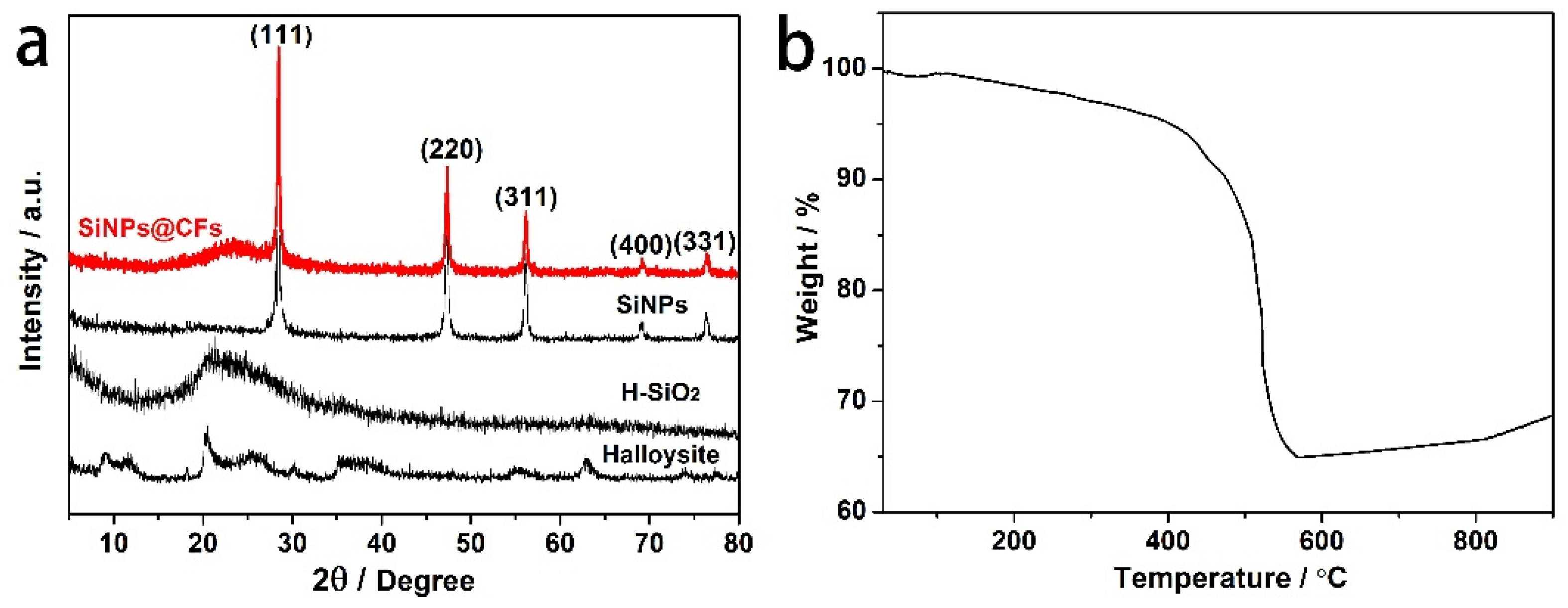
3.1. XRD Analysis
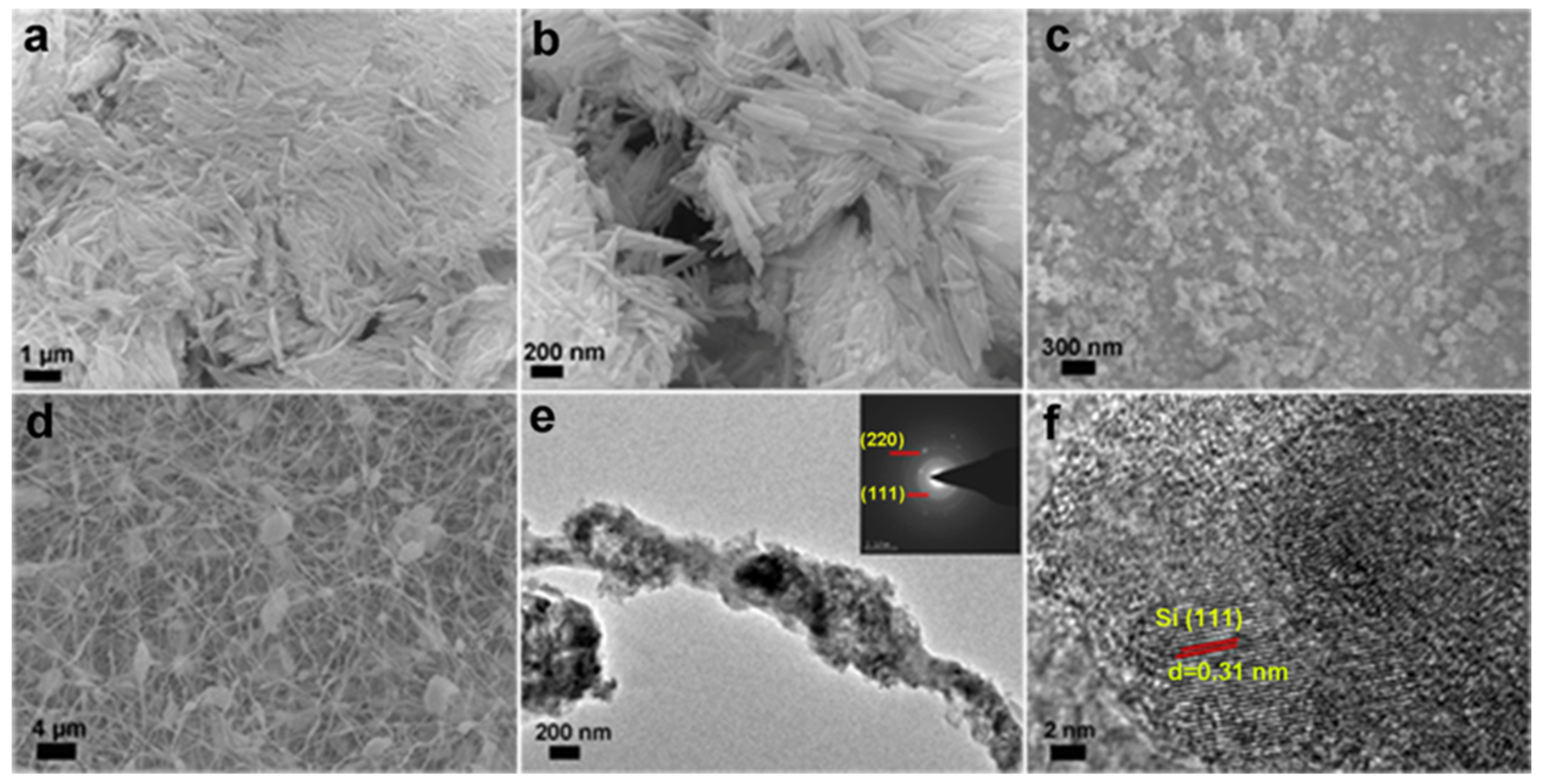
3.2. SEM and TEM Analysis
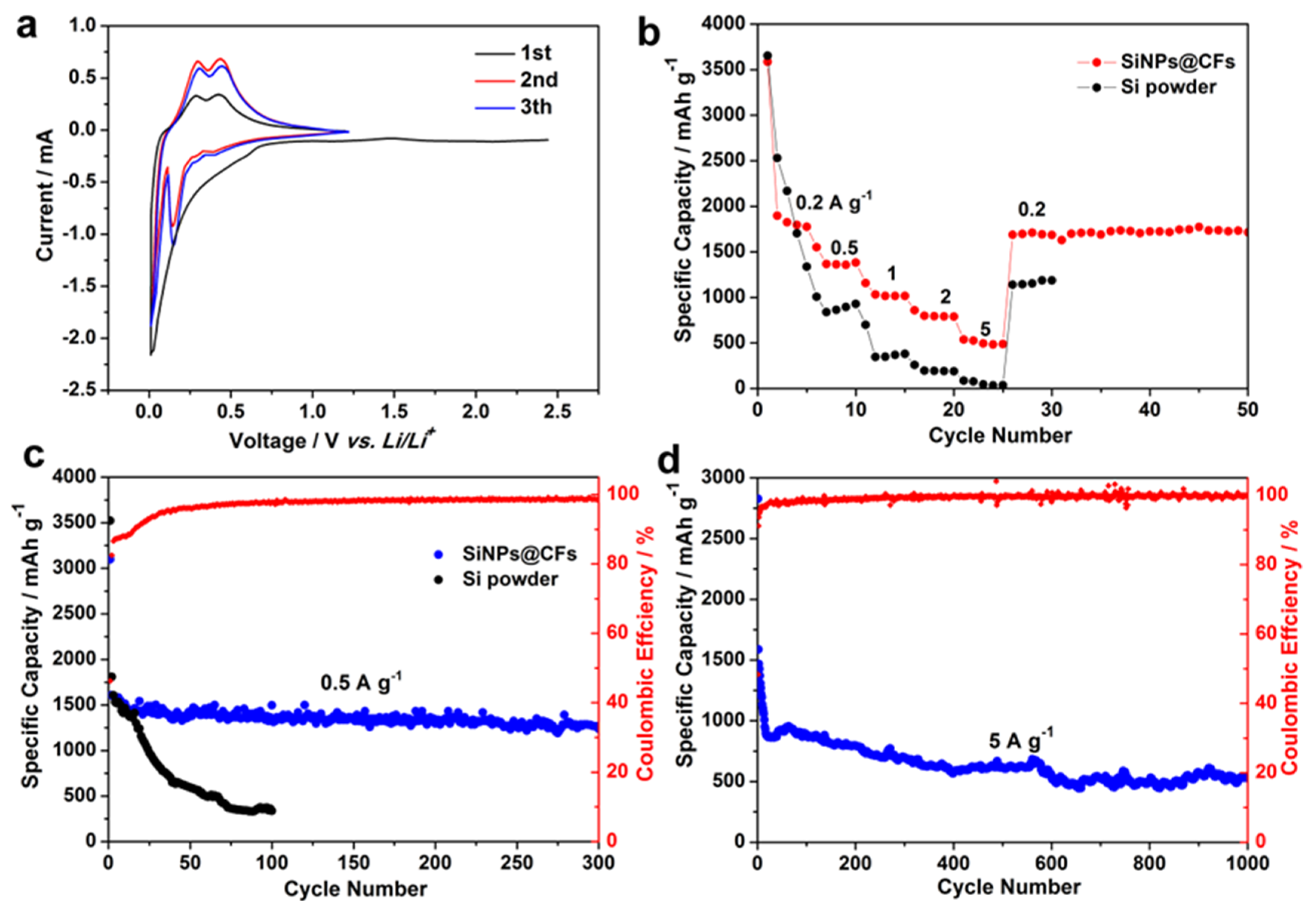
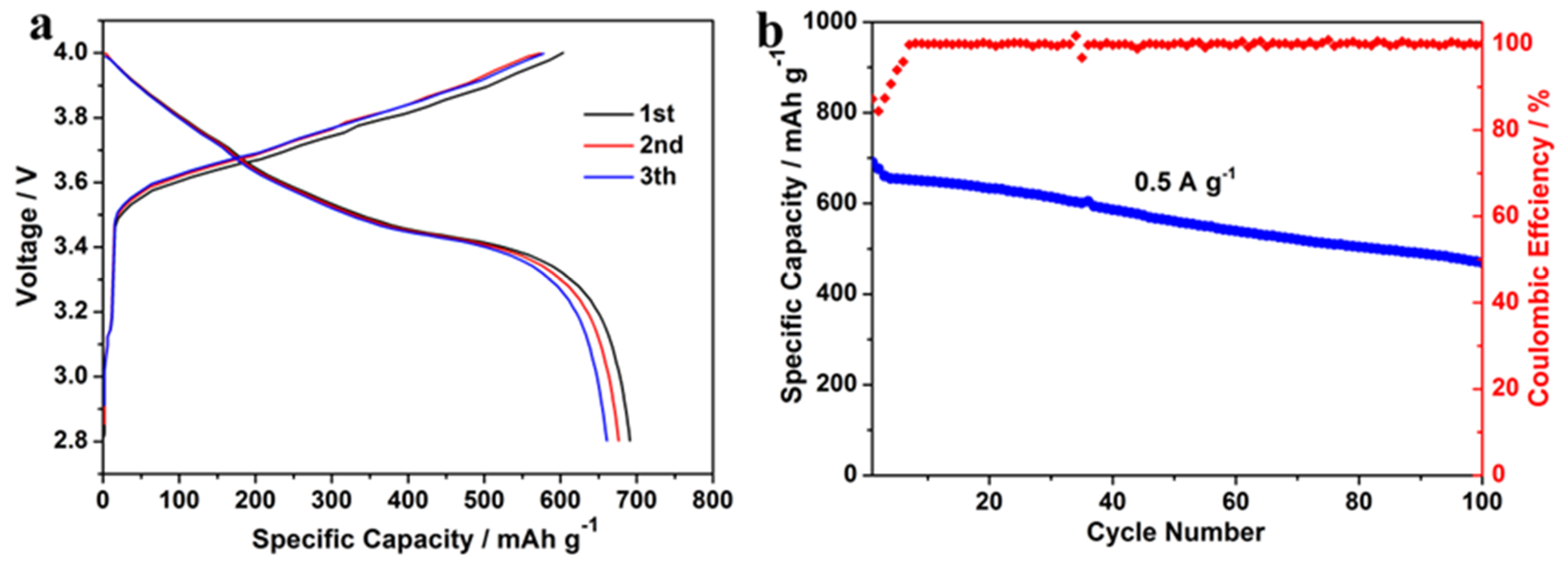
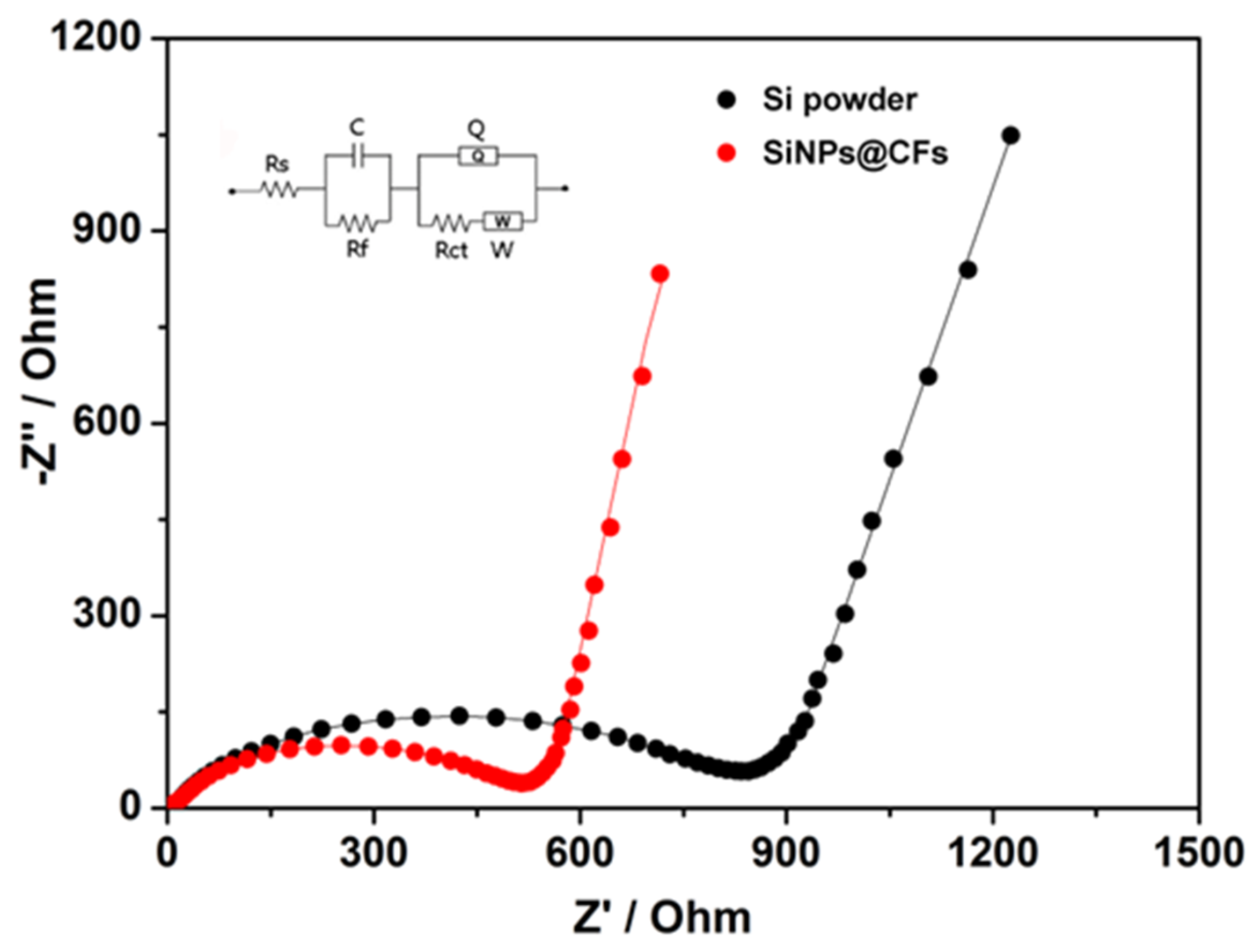
3.3. Electrochemical Performance Analysis
4. Discussion
5. Conclusions
Supplementary Materials
Author Contributions
Acknowledgments
Conflicts of Interest
References
- Hadjipaschalis, I.; Poullikkas, A.; Efthimiou, V. Overview of current and future energy storage technologies for electric power applications. Renew. Sustain. Energy Rev. 2009, 13, 1513–1522. [Google Scholar] [CrossRef]
- Sternberg, A.; Bardow, A. Power-to-What?—Environmental assessment of energy storage systems. Energy Environ. Sci. 2015, 8, 389–400. [Google Scholar] [CrossRef]
- Kousksou, T.; Bruel, P.; Jamil, A.; El Rhafiki, T.; Zeraouli, Y. Energy storage: Applications and challenge. Sol. Energy Mater. Sol. Cells 2014, 120, 59–80. [Google Scholar] [CrossRef]
- Simon, P.; Gogotsi, Y.; Dunn, B. Materials science. Where do batteries end and supercapacitors begin? Science 2014, 343, 1210–1211. [Google Scholar] [CrossRef] [PubMed]
- Liu, S.; Zhou, J.; Cai, Z.; Fang, G.; Pan, A.; Liang, S. Nb2O5 microstructures: A high-performance anode for lithium ion batteries. Nanotechnology 2016, 27, 46LT01. [Google Scholar] [CrossRef] [PubMed]
- Goriparti, S.; Miele, E.; De Angelis, F.; Di Fabrizio, E.; Proietti Zaccaria, R.; Capiglia, C. Review on recent progress of nanostructured anode materials for Li-ion batteries. J. Power Sources 2014, 257, 421–443. [Google Scholar] [CrossRef]
- Kundu, M.; Karunakaran, G.; Kumari, S.; Minh, N.V.; Kolesnikov, E.; Gorshenkov, M.V.; Kuznetsov, D. One-pot ultrasonic spray pyrolysis mediated hollow Mg0.25Cu0.25Zn0.5Fe2O4/NiFe2O4 nanocomposites: A promising anode material for high-performance lithium-ion battery. J. Alloys Compd. 2017, 725, 665–672. [Google Scholar] [CrossRef]
- Kundu, M.; Karunakaran, G.; Kolesnikov, E.; Sergeevna, V.E.; Kumari, S.V.; Gorshenkov, M.; Kuznetsov, D. Hollow NiCo2O4 nano-spheres obtained by ultrasonic spray pyrolysis method with superior electrochemical performance for lithium-ion batteries and supercapacitors. J. Ind. Eng. Chem. 2018, 59, 90–98. [Google Scholar] [CrossRef]
- Kundu, M.; Karunakaran, G.; Kolesnikov, E.; Dmitry, A.; Gorshenkov, M.V.; Kuznetsov, D. Hollow (Co0.62Fe1.38)FeO4/NiCo2O4 nanoboxes with porous shell synthesized via chemical precipitation: A novel form as a high performance lithium ion battery anode. Microporous Microporous Mater. 2017, 247, 9–15. [Google Scholar] [CrossRef]
- Kundu, M.; Karunakaran, G.; Minh, N.V.; Kolesnikov, E.; Gorshenkov, M.V.; Kuznetsov, D. Hollow Cu0.10Mg0.40Zn0.50Fe2O4/Ca2Ni5 nanocomposite: A novel form as anode material in lithium-ion battery. J. Alloys Compd. 2017, 710, 501–509. [Google Scholar] [CrossRef]
- Li, X.; Gu, M.; Hu, S.; Kennard, R.; Yan, P.; Chen, X.; Wang, C.; Sailor, M.J.; Zhang, J.G.; Liu, J. Mesoporous silicon sponge as an anti-pulverization structure for high-performance lithium-ion battery anodes. Nat. Commun. 2014, 5, 4105. [Google Scholar] [CrossRef] [PubMed]
- Wu, H.; Yu, G.; Pan, L.; Liu, N.; McDowell, M.T.; Bao, Z.; Cui, Y. Stable Li-ion battery anodes by in-situ polymerization of conducting hydrogel to conformally coat silicon nanoparticles. Nat. Commun. 2013, 4, 1943. [Google Scholar] [CrossRef] [PubMed]
- Zhao, K.; Pharr, M.; Wan, Q.; Wang, W.L.; Kaxiras, E.; Vlassak, J.J.; Suo, Z. Concurrent reaction and plasticity during initial lithiation of crystalline silicon in lithium-ion batteries. J. Electrochem. Soc. 2012, 159, A238–A243. [Google Scholar] [CrossRef]
- Zhou, X.; Yin, Y.X.; Wan, L.J.; Guo, Y.G. Self-Assembled Nanocomposite of Silicon Nanoparticles Encapsulated in Graphene through Electrostatic Attraction for Lithium-Ion Batteries. Adv. Energy Mater. 2012, 2, 1086–1090. [Google Scholar] [CrossRef]
- Obrovac, M.N.; Christensen, L.; Le, D.B.; Dahn, J.R. Alloy Design for Lithium-Ion Battery Anodes. J. Electrochem. Soc. 2007, 154, A849. [Google Scholar] [CrossRef]
- Zhou, X.; Yin, Y.X.; Wan, L.J.; Guo, Y.G. Facile synthesis of silicon nanoparticles inserted into graphene sheets as improved anode materials for lithium-ion batteries. Chem. Commun. 2012, 48, 2198–2200. [Google Scholar] [CrossRef] [PubMed]
- Cui, L.F.; Hu, L.; Choi, J.W.; Cui, Y. Light-weight free-standing carbon nanotube-silicon films for anodes of lithium ion batteries. ACS Nano 2010, 4, 3671–3678. [Google Scholar] [CrossRef] [PubMed]
- Song, T.; Xia, J.; Lee, J.H.; Lee, D.H.; Kwon, M.S.; Choi, J.M.; Wu, J.; Doo, S.K.; Chang, H.; Park, W.I.; et al. Arrays of sealed silicon nanotubes as anodes for lithium ion batteries. Nano Lett. 2010, 10, 1710–1716. [Google Scholar] [CrossRef] [PubMed]
- Chockla, A.M.; Harris, J.T.; Akhavan, V.A.; Bogart, T.D.; Holmberg, V.C.; Steinhagen, C.; Mullins, C.B.; Stevenson, K.J.; Korgel, B.A. Silicon nanowire fabric as a lithium ion battery electrode material. J. Am. Chem. Soc. 2011, 133, 20914–20921. [Google Scholar] [CrossRef] [PubMed]
- Zhou, Y.; Jiang, X.; Chen, L.; Yue, J.; Xu, H.; Yang, J.; Qian, Y. Novel mesoporous silicon nanorod as an anode material for lithium ion batteries. Electrochim. Acta 2014, 127, 252–258. [Google Scholar] [CrossRef]
- Yao, Y.; McDowell, M.T.; Ryu, I.; Wu, H.; Liu, N.; Hu, L.; Nix, W.D.; Cui, Y. Interconnected silicon hollow nanospheres for lithium-ion battery anodes with long cycle life. Nano Lett. 2011, 11, 2949–2954. [Google Scholar] [CrossRef] [PubMed]
- Schroder, K.; Alvarado, J.; Yersak, T.A.; Li, J.; Dudney, N.; Webb, L.J.; Meng, Y.S.; Stevenson, K.J. The effect of fluoroethylene carbonate as an additive on the solid electrolyte Interphase on silicon lithium-ion electrodes. Chem. Mater. 2015, 27, 5531–5542. [Google Scholar] [CrossRef]
- Molina Piper, D.; Evans, T.; Leung, K.; Watkins, T.; Olson, J.; Kim, S.C.; Han, S.S.; Bhat, V.; Oh, K.H.; Buttry, D.A.; et al. Stable silicon-ionic liquid interface for next-generation lithium-ion batteries. Nat. Commun. 2015, 6, 6230. [Google Scholar] [CrossRef] [PubMed]
- Yang, J.; Wang, Y.X.; Chou, S.L.; Zhang, R.; Xu, Y.; Fan, J.; Zhang, W.X.; Liu, H.K.; Zhao, D.; Dou, S.X. Yolk-shell silicon-mesoporous carbon anode with compact solid electrolyte interphase film for superior lithium-ion batteries. Nano Energy 2015, 18, 133–142. [Google Scholar] [CrossRef]
- Chen, S.; Bao, P.; Huang, X.; Sun, B.; Wang, G. Hierarchical 3D mesoporous silicon@graphene nanoarchitectures for lithium ion batteries with superior performance. Nano Res. 2013, 7, 85–94. [Google Scholar] [CrossRef]
- Fan, Y.; Zhang, Q.; Xiao, Q.; Wang, X.; Huang, K. High performance lithium ion battery anodes based on carbon nanotube–silicon core–shell nanowires with controlled morphology. Carbon 2013, 59, 264–269. [Google Scholar] [CrossRef]
- Liu, X.H.; Zhong, L.; Huang, S.; Mao, S.X.; Zhu, T.; Huang, J.Y. Size-dependent fracture of silicon nanoparticles during lithiation. ACS Nano 2012, 6, 1522–1531. [Google Scholar] [CrossRef] [PubMed]
- Hu, Y.S.; Adelhelm, P.; Smarsly, B.M.; Maier, J. Highly Stable Lithium Storage Performance in a Porous Carbon/Silicon Nanocomposite. ChemSusChem 2010, 3, 231–235. [Google Scholar] [CrossRef] [PubMed]
- Hwang, T.H.; Lee, Y.M.; Kong, B.S.; Seo, J.S.; Choi, J.W. Electrospun core-shell fibers for robust silicon nanoparticle-based lithium ion battery anodes. Nano Lett. 2012, 12, 802–807. [Google Scholar] [CrossRef] [PubMed]
- Liu, S.; Cai, Z.; Zhou, J.; Zhu, M.; Pan, A.; Liang, S. High-performance sodium-ion batteries and flexible sodium-ion capacitors based on Sb2X3 (X = O, S)/carbon fiber cloth. J. Mater. Chem. A 2017, 5, 9169–9176. [Google Scholar] [CrossRef]
- Wang, X.; Lu, X.; Liu, B.; Chen, D.; Tong, Y.; Shen, G. Flexible Energy-Storage Devices: Design Consideration and Recent Progress. Adv. Mater. 2014, 26, 4763–4782. [Google Scholar] [CrossRef] [PubMed]
- Ouyang, J.; Mu, D.; Zhang, Y.; Yang, H. Mineralogy and physico-chemical data of two newly discovered halloysite in China and their contrasts with some typical minerals. Minerals 2018, 8, 108. [Google Scholar] [CrossRef]
- Yu, L.; Wang, H.; Zhang, Y.; Zhang, B.; Liu, J. Recent advances in halloysite nanotube derived composites for water treatment. Environ. Sci. 2016, 3, 28–44. [Google Scholar] [CrossRef]
- Shu, Z.; Zhang, Y.; Yang, Q.; Yang, H. Halloysite Nanotubes Supported Ag and ZnO Nanoparticles with Synergistically Enhanced Antibacterial Activity. Nanoscale Res. Lett. 2017, 12, 135. [Google Scholar] [CrossRef] [PubMed]
- Borrego-Sánchez, A.; Awad, M.; Sainz-Díaz, C. Molecular modeling of adsorption of 5-aminosalicylic acid in the halloysite nanotube. Minerals 2018, 8, 61. [Google Scholar] [CrossRef]
- Zhou, X.; Wu, L.; Yang, J.; Tang, J.; Xi, L.; Wang, B. Synthesis of nano-sized silicon from natural halloysite clay and its high performance as anode for lithium-ion batteries. J. Power Sources 2016, 324, 33–40. [Google Scholar] [CrossRef]
- Luo, W.; Wang, X.; Meyers, C.; Wannenmacher, N.; Sirisaksoontorn, W.; Lerner, M.M.; Ji, X. Efficient fabrication of nanoporous Si and Si/Ge enabled by a heat scavenger in magnesiothermic reactions. Sci. Rep. 2013, 3, 2222. [Google Scholar] [CrossRef] [PubMed]
- Luo, Z.; Xiao, Q.; Lei, G.; Li, Z.; Tang, C. Si nanoparticles/graphene composite membrane for high performance silicon anode in lithium ion batteries. Carbon 2016, 98, 373–380. [Google Scholar] [CrossRef]


© 2018 by the authors. Licensee MDPI, Basel, Switzerland. This article is an open access article distributed under the terms and conditions of the Creative Commons Attribution (CC BY) license (http://creativecommons.org/licenses/by/4.0/).
Share and Cite
Liu, S.; Zhang, Q.; Yang, H.; Mu, D.; Pan, A.; Liang, S. Fabrication of Si Nanoparticles@Carbon Fibers Composites from Natural Nanoclay as an Advanced Lithium-Ion Battery Flexible Anode. Minerals 2018, 8, 180. https://doi.org/10.3390/min8050180
Liu S, Zhang Q, Yang H, Mu D, Pan A, Liang S. Fabrication of Si Nanoparticles@Carbon Fibers Composites from Natural Nanoclay as an Advanced Lithium-Ion Battery Flexible Anode. Minerals. 2018; 8(5):180. https://doi.org/10.3390/min8050180
Chicago/Turabian StyleLiu, Sainan, Qiang Zhang, Huaming Yang, Dawei Mu, Anqiang Pan, and Shuquan Liang. 2018. "Fabrication of Si Nanoparticles@Carbon Fibers Composites from Natural Nanoclay as an Advanced Lithium-Ion Battery Flexible Anode" Minerals 8, no. 5: 180. https://doi.org/10.3390/min8050180
APA StyleLiu, S., Zhang, Q., Yang, H., Mu, D., Pan, A., & Liang, S. (2018). Fabrication of Si Nanoparticles@Carbon Fibers Composites from Natural Nanoclay as an Advanced Lithium-Ion Battery Flexible Anode. Minerals, 8(5), 180. https://doi.org/10.3390/min8050180