Article

Iron Recovery from Discarded Copper Slag in a RHF Direct Reduction and Subsequent Grinding/Magnetic Separation Process

1
Key Laboratory of High-Efficient Mining and Safety of Metal Mines, Ministry of Education, University of Science and Technology Beijing, Beijing 100083, China
2
Beijing Shenwu Environment & Energy Technology Corp., Beijing 102200, China
*
Author to whom correspondence should be addressed.
Minerals 2016, 6(4), 119; https://doi.org/10.3390/min6040119
Submission received: 4 August 2016 / Revised: 16 October 2016 / Accepted: 20 October 2016 / Published: 3 November 2016

Abstract

:
Studies on the direct reduction of carbon-bearing pellets made from discarded copper slag have been conducted in this paper. They include the influences of reduction coal content, limestone content, industrial sodium carbonate content, reduction temperature, reduction time and layers of carbon-bearing pellets on reduction effect. Finally, the optimum conditions have been obtained. The pilot scale experiment results show that the optimum conditions are the mass proportion of discarded copper slag, reduction coal, limestone and industrial sodium carbonate of 100:25:10:3, the reduction temperature of 1280 °C for the reduction time of 35 min, three layers (approximately 42 mm) of carbon-bearing pellets—this was the basis on which the pilot tests in a rotary hearth furnace (RHF) were conducted. The iron products obtained from the pilot tests under such conditions have an iron grade of 90.35% with an iron recovery rate of 89.70%. The mechanism research based on the analysis results of X-ray diffraction (XRD), scanning electron microscopy (SEM) and energy dispersive spectroscopy (EDS) indicates that fayalite (2FeO·SiO2) and magnetite (Fe3O4) in the copper slag are reduced into metallic Fe in the direct reduction (DR) process, and the mass and heat transfer become stronger from the bottom to the top layer of the pellets, resulting in a rising iron recovery rate.

1. Introduction

At present, copper production in China mainly comes in a pyrometallurgical process. Generally, for one ton of copper, 2.2 tons of discarded copper slag is generated, and in China, the amount of discharging copper slag exceeds 10 million tons per year [1], with the accumulated amount of copper slag over the years exceeding 120 million tons [2]. Iron can reach about 48 million tons in this copper slag, based on a calculation of 40% Fe content in the slag. No such costs for operations such as mining or beneficiation (usually required for iron concentrates) have to incur for copper slag as it is discarded from a copper smelting plant. That is to say, the copper slag is a kind of costless raw material. Thanks to the rich zinc content in such copper slag, the same can also be recovered in the form of zinc oxide powder when the iron element is recovered. Therefore, copper slag with 40% Fe content is a better iron resource economically than conventional iron deposits.
Fe exists in copper slag mainly in the form of fayalite (2FeO·SiO2), which is hard to recover. Current disposal practice adopted by many enterprises is stockpiling, which not only occupies large pieces of land, but also pollutes the environment. Furthermore, a lot of valuable metals (Fe, Cu, Zn, etc.,) settled in the slag cannot be effectively utilized. Main methods in use for iron recovery from copper slag include direct beneficiation for iron recovery [3], oxidative modification [4,5] of iron oxide for iron recovery, smelting reduction for iron recovery [6,7], and direct reduction (DR) for iron recovery [8,9], etc. However, iron recovery rates in direct beneficiation and oxidative modification are too low, whereas energy consumption of the smelting reduction is too high. By using DR followed by a magnetic separation process for iron recovery from copper slag, Yang [10] obtained iron powder of 92.05% iron content with an iron recovery rate of 81.01%, and Wang [11] obtained iron powder of 92.96% iron content with an iron recovery rate of 93.49%. Both of their tests have achieved good results. However, the above researches, which are technically feasible, have been done only in the bench test of the laboratory, but a lack of industrial equipment to process copper slag with coal-based DR in large scale. In practice, coal-based DR facilities include tunnel kilns [12], rotary kilns [13], rotary hearth furnaces (RHF) [14,15], etc. The tunnel kiln features a low capacity, high energy consumption, and a severe production environment, while the rotary kiln for the DR process is usually applied in large-scale to laterite nickel ore reduction, which has negative effects on operation due to ringlet formation resulting from high temperature. Therefore, the reduction facilities with low energy consumption are in urgent demand for the large-scaled treatment of industrial production. This paper takes copper slag from a domestic copper smelting plant as the object of study. In the studies, the basic and pilot plant tests have been conducted following the RHF DR and grinding/magnetic separation process flow, and the reduction mechanism has been analyzed.

2. Experimental

2.1. Materials

The raw material in the tests is the discarded copper slag (hereinafter referred to as copper slag) of a domestic copper smelting plant. Its particle size is of −0.045 mm accounts for 74.48% of the total. The major chemical composition of the copper slag is listed in Table 1 as below. The Fe content in the copper slag is up to 40.78% and Zn content in it is 1.35%. Both of them have certain recovery values.
Figure 1 is the X-ray diffraction (XRD) patterns of the selected copper slag. With reference to the chemical composition of Table 1, it can be seen that the iron mineral in the slag is mainly fayalite (2FeO·SiO2), which is generally hard to recover in those conventional beneficiation processes. The anthracite, with a fixed carbon content of 82.47%, a volatile matter of 6.51% and an ash content of 11.35%, is used as a reducing agent for the tests. The limestone with a CaCO3 content of 90%, and the pure industrial alkali with a sodium carbonate content of 98% are used as the additives.

2.2. Theoretical Analysis

Mixed with the reducing agent and the additives, the copper slag is made into the carbon-bearing pellets (12–16 mm), which should be dried before being charged into a RHF. After passing the preheating zone, middle temperature zone, high temperature zone and cooling zone, 85% of the iron oxides in the pellets are reduced into metallic Fe. Furthermore, the ZnO in the pellets are reduced into metallic Zn, which is collected by a bag-filter system. In order to speed up the reactions, an appropriate amount of limestone and industrial sodium carbonate are added to the pellets, and major chemical reactions taking place are shown as below.

2.2.1. Reduction Mechanism of Fayalite

Reduction reactions of fayalite can be obtained from the combination of Equations (1) and (2) and its result is shown in Equation (3).
2FeO(s) + 2C(s) → 2Fe(s)+2CO(g) ∆rGmθ = 295808 − 300.44T (J·mol−1)
2FeO(s) + SiO2(s) → Fe2SiO4(s) ∆rGmθ = −36200 + 21.09T (J·mol−1)
Fe2SiO4(s) + 2C(s) → 2Fe(s) + SiO2(s) + 2CO(g) ∆rGmθ = 354140 − 341.59T (J·mol−1)
From the calculations, it can be seen that Fe2SiO4 is more difficult to reduce than FeO because the dissociation temperature of the former is higher than that of the latter. Since both Equations (1) and (3) are intensely endothermic, to raise the roasting reduction temperature will help accelerate the reducing reaction rate. Besides, Equation (1) can be formed from the combination of the following two reactions:
C(s) + CO2(g) → 2CO(g)
FeO(s) + CO(g) → Fe(s) + CO2(g)

2.2.2. Recovery Mechanism of Zn

ZnO in the dust is reduced at high temperature into the metallic Zn, which is vaporized and separated in the form of metal vapor before being reoxidized while flowing along with the flue gas in the flue duct, and being collected in the form of oxides. The mechanism includes several reactions under high temperature:
ZnO(s) + C(s) → Zn(g) + CO(g)
ZnO(s) + CO(g) → Zn(g) + CO2(g)
ZnFe2O4(s) + 2Fe(s/l) → Zn(g) + 4FeO(s)
The above reactions are endothermic, so the higher the temperature, the more conducive to reduction the reactions are. At higher temperature, thermodynamic conditions for Zn vaporization will be greatly improved.

2.2.3. Reaction Mechanism of Additives

Since copper slag is a kind of acidic slag, the addition of calcium oxide in the DR process results in the following reactions:
Fe2SiO4(s)+2CaO(s) +2C(s) →Ca2SiO4(s) + 2Fe(s) + 2CO(g) ∆rGmθ = 235347 − 310.71T (J·mol−1)
Na2CO3(s) + SiO2(s) → Na2SiO3(s) + CO2(g)
From the above reactions, it can be seen that the higher temperature is, the more conducive to reduction the reactions are. Fe2SiO4 can also be reduced into metallic iron at the higher reducing temperature. By adding CaO in the DR process, the reduction temperature of Fe2SiO4 can be effectively lowered, thus the DR capability has been increased and the DR of Fe2SiO4 has been enhanced. Silicates, formed by the addition of sodium carbonate as basic oxides to be combined with SiO2, can destroy the iron olivine structure of the copper slag and increase FeO activity, thus accelerating the reduction of iron oxides.

2.3. Experimental Procedure

The testing order is followed with the basic tests, carried out first before the results being verified at the pilot plant tests. The procedures are as follows: mixing of raw materials → pelleting → drying → DR roasting → water cooling → grinding/magnetic separation → final DR product. The focus is on the quality of the final DR product and the iron recovery rate, with the calculation method used as follows:
ε = (W1 × β)/(W × α) × 100%
Where ε is the iron recovery rate, W1 is the weight of magnetically separated iron powder, β is the Fe content of iron powder, W is the weight of discarded copper slag, and α is the iron content of copper slag, respectively.

3. Results and Discussions

The early tests indicated that when one layer of pellets were under roasting, the highest reduction temperature could only be kept at 1200 °C, because the higher temperature could cause pellets melting, which is not conducive to the RHF production. When two layers of pellets were laid for roasting, reduction temperature could be increased and no pellets melting took place, thus a good pellet shape can be maintained. Under this condition, many factors that affect Fe content and recovery rate of the iron powder were also examined, such as the amount of reduction coal, quantity of additives, such as limestone and industrial sodium carbonate, reduction temperature and reduction time.

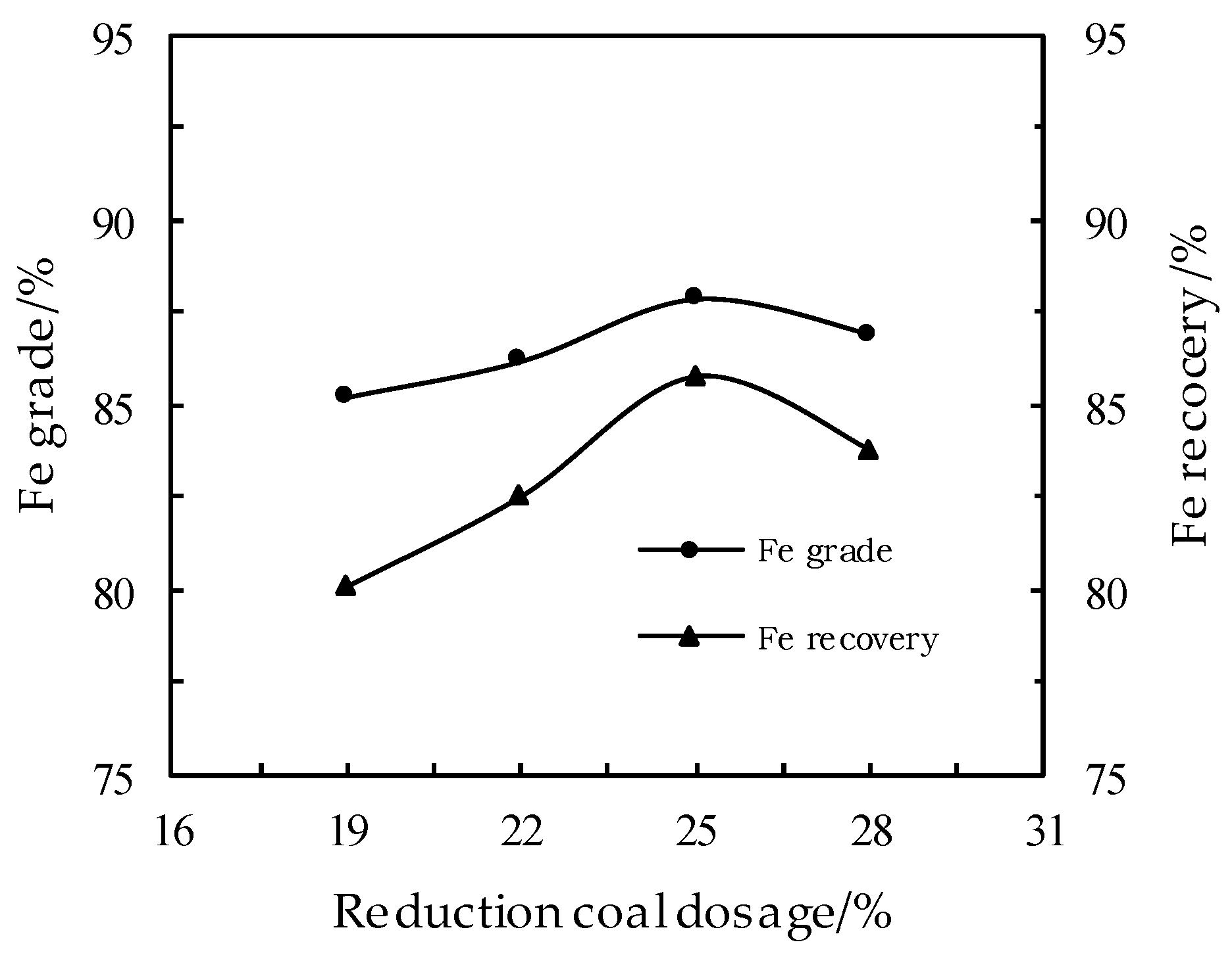
3.1. Effect of Reduction Coal Dosage on the DR Process

The exploratory experiments show that 5% of bentonite should be added into the copper slag pellets, with a drop strength (number of non-breakage of a pellet drop at the height of 0.5 m onto a steel plate) of carbon-containing pellets being reached over six times, thus meeting the requirement of the RHF process. The examinations of the effect of reduction coal dosage on the product’s Fe content and recovery rates were carried out under the following conditions: limestone dosage of 15%, sodium carbonate dosage of 0.5%, reduction temperature of 1250 °C, reduction time of 30 min, grinding fineness of −0.074 mm accounting for 72.1% of the copper slag mix and magnetic field strength of 143.31 kA/m. The result is shown in Figure 2 below.
Figure 2 shows that, with the increase of the dosage of the reduction coal, the Fe content of the iron powder lies between 85% and 87%, and the iron recovery rate firstly slightly rises then declines, therefore the optimum dosage of reduction coal is set at 25%. With the lower dosage of the reduction coal, parts of the iron oxides remain unreduced, whereas the higher dosage of the reduction coal will hinder the agglomeration of the reduced iron grain, thus causing the negative impacts on the subsequent grinding/magnetic separation for iron recovery.

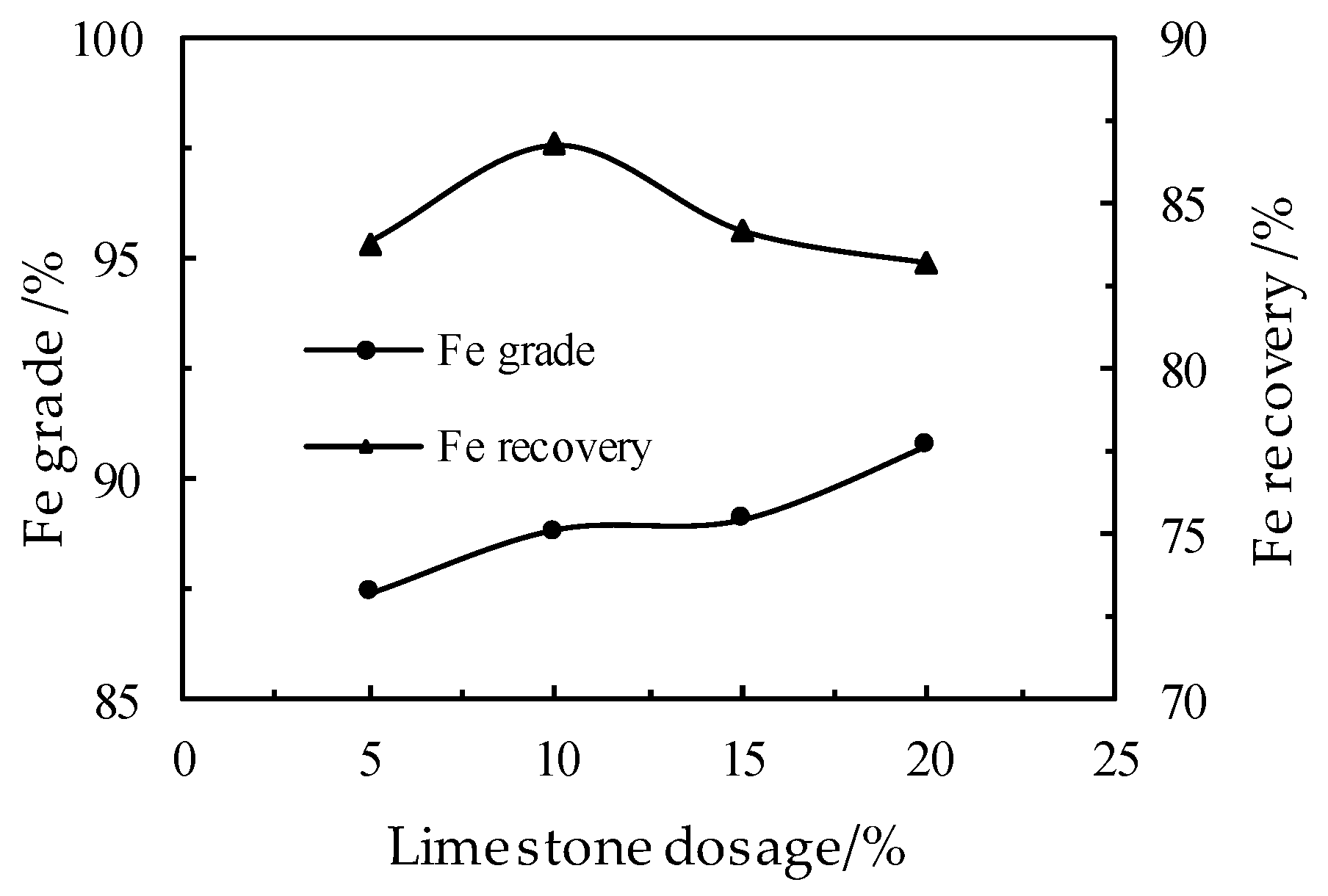
3.2. Effect of the Limestone Dosage on the DR Process

The examination of the effect of the limestone dosage on the product’s Fe content and recovery rates were conducted. The proportion of copper slag, reduction coal and industrial sodium carbonate was fixed at 100:25:0.5, with the other conditions of reduction and grinding/magnetic separation remaining unchanged. The result is shown in Figure 3 below.
Figure 3 shows that, with the increase in the dosage of the limestone, the iron grade has a tendency to rise, and the iron recovery rate rises first then declines. Furthermore, with the limestone dosage of 10% of the copper slag, the iron grade can reach 88.79% with the iron recovery rate of 86.75%. However, with the limestone dosage of 15% and 20%, partial melting of the upper layer of carbon-containing pellets obstructs the heat transfer to the lower layers of pellets, thus the reducing effect is negatively impacted. Therefore, the optimal dosage of the limestone is set at 10%.

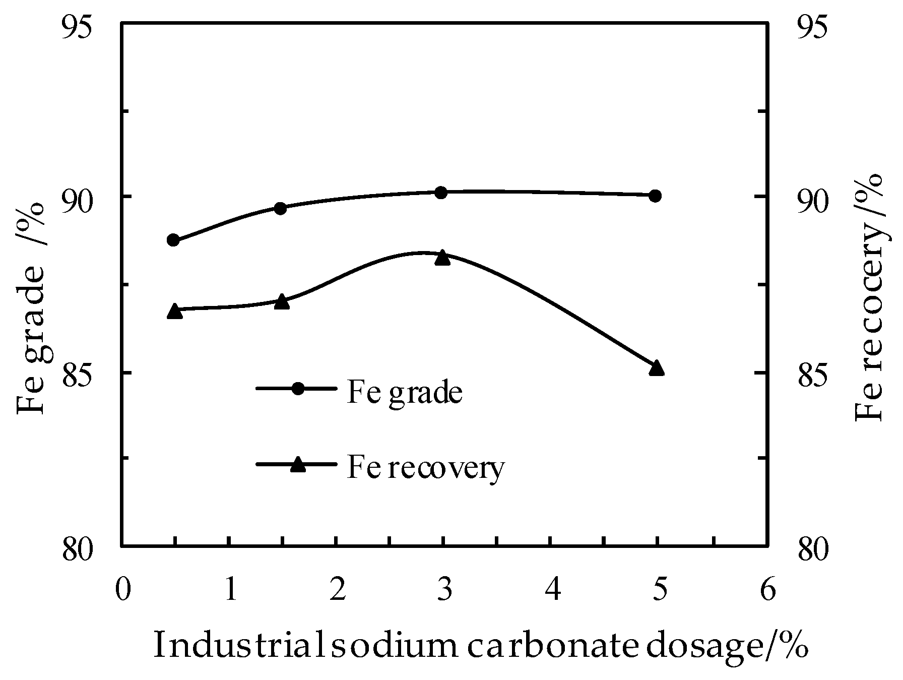
3.3. Effect of the Industrial Sodium Carbonate Dosage on the DR Process

Examinations of the effect of industrial sodium carbonate dosage on the product’s Fe content and recovery rate were conducted. The proportion of copper slag, reduction coal and industrial sodium carbonate was fixed at 100:25:10, with the other conditions of reduction and grinding/magnetic separation remaining unchanged. The result is shown in Figure 4.
Figure 4 shows that, both the iron grade and the iron recovery rate show a tendency to increase at first and then decrease with the increase in the dosage of the industrial sodium carbonate. This is because more and more silicates are formed from the combination of sodium carbonate with SiO2, which destroys the iron silicate mineral structure of the copper slag, and enhances the reduction of the iron oxides. However, a higher dosage of sodium carbonate leads to the top carbon-containing pellets melting, thus obstructing further reduction of the lower layers of pellets. As a result, the optimal dosage of the industrial sodium carbonate is set at 3%.

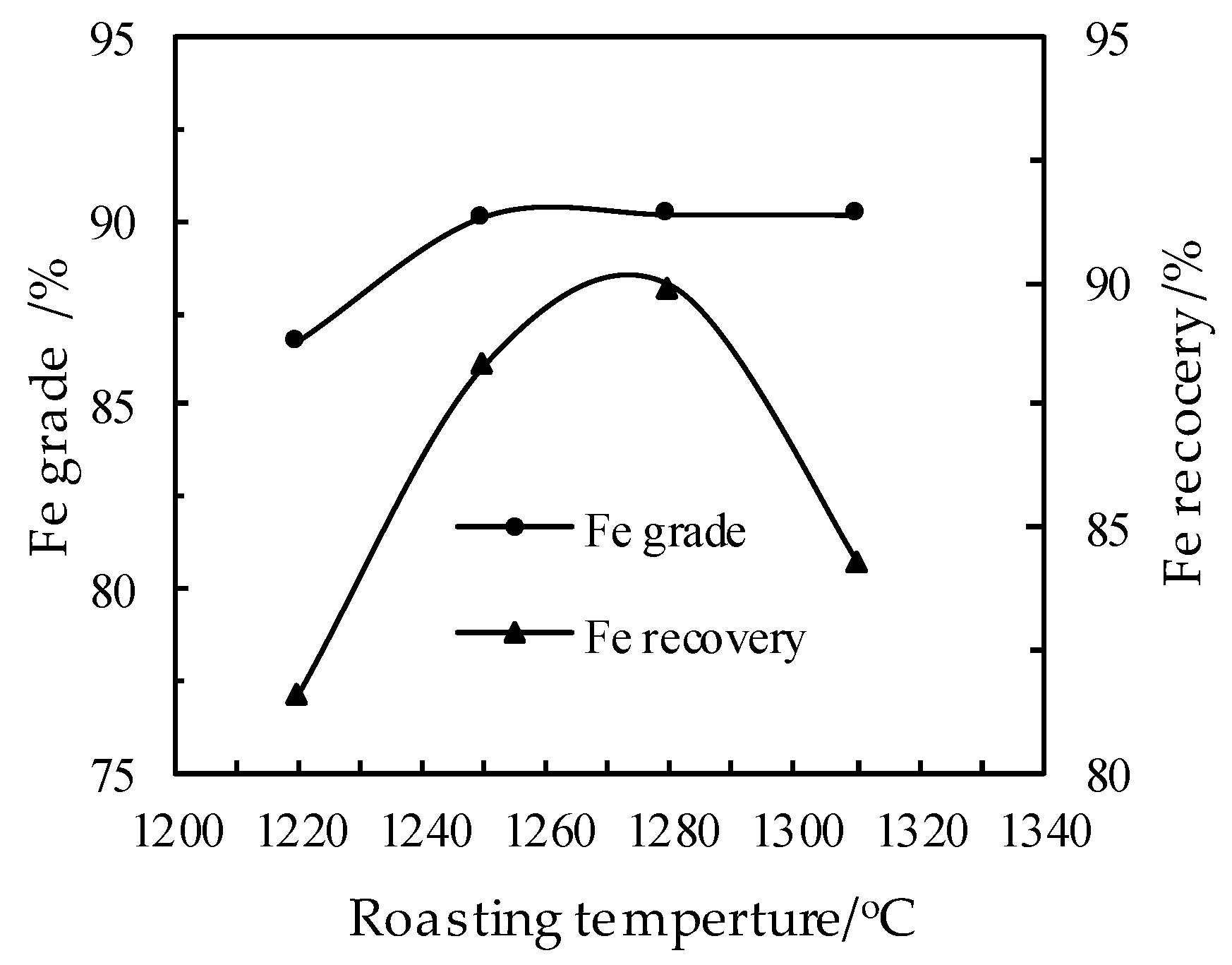
3.4. Effect of the Roasting Temperature on the DR Process

From all the above tests, the optimal proportion of the copper slag, the reduction coal, the limestone and the industrial sodium carbonate was fixed at 100:25:10:3. Tests on the reduction temperature were conducted on such a basis, with the details shown in Figure 5.
Figure 5 shows that, with the increase in the reduction temperature, the iron grade and the recovery rate have a tendency to first rise before declining, and at the reduction temperature of 1280 °C, an iron grade of 90.18% can be obtained at the highest iron recovery rate of 89.91%. As the temperature continues rising, the thermodynamic conditions for mass and heat transfer in the lower pellet layer deteriorate. Therefore, the optimal reduction temperature is 1280 °C.

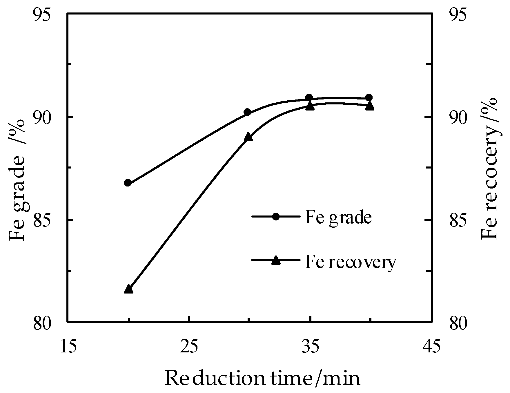
3.5. Effect of the Reduction Time on the DR Process

With the proportioning and grinding/magnetic separation conditions of the raw materials remaining unchanged, the tests on reduction time were conducted at a reduction temperature of 1280 °C, and the iron grade and iron recovery rate showed a tendency to increase. With the reduction time set at 35 min, an iron grade of 90.85% and an iron recovery rate of 90.49% could be obtained. Further increase in the reduction time did not result in any considerable improvement, and the optimal reduction time is set at 35 min, from a cost-saving perspective. Details are shown in Figure 6.

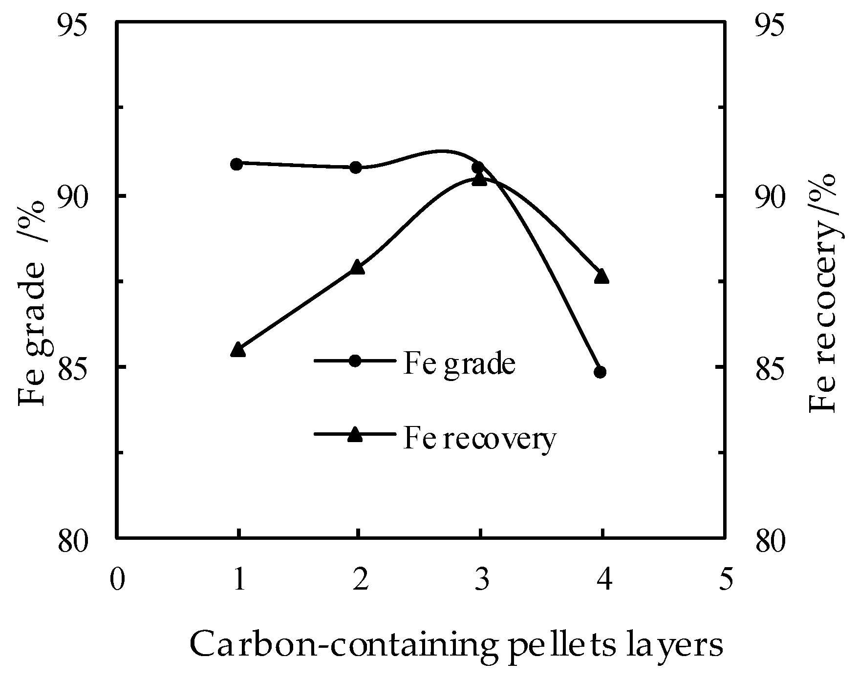
3.6. Effect of the Layers of the Carbon-Bearing Pellets on the DR Process

All the above tests were conducted on two layers of carbon-bearing pellets, with such conditions as the proportion, the reduction temperature, the reduction time and the grinding/magnetic separation remaining unchanged. Further tests were carried out on the impacts of the pellet layers from 1 to 4 on the reduction. The details are shown in Figure 7.
It can be seen from Figure 7 that the distribution thickness of three layers (about 42 mm) of the carbon-containing pellets can have the best reduction effect with the highest iron grade and recovery rate obtainable. When the carbon-containing pellets are in four layers, heat transfer to the lower layers deteriorates with reduction results being negatively affected, and the iron grade and the recovery rate greatly declining.

4. The Pilot-Scale Tests via RHF

The optimal conditions obtained from the basics tests are the proportion of the copper slag, the reduction coal, the limestone, the industrial sodium carbonate fixed as 100:25:10:3, at a distribution thickness of three pellet layers, and a reduction temperature of 1280 °C for a reduction time of 35 min. These conditions were applied to the pilot-scale tests on a RHF having an outer diameter of 10 m, and a processing capability of 2 t/h.
The metallization pellets discharged from the RHF went through a grinding/magnetic separation process, with a grinding fineness of −0.074 mm accounting for 72.10% of the total and a magnetic field strength of 143.31 kA/m in the first stage, and a grinding fineness of −0.074 mm accounting for 50.89% of the rest and a magnetic field strength of 95.54 kA/m in the second stage. The iron content of the obtained iron products is 90.3% with an iron recovery rate of 89.70%.

5. Studies of Mechanisms and Product Analysis

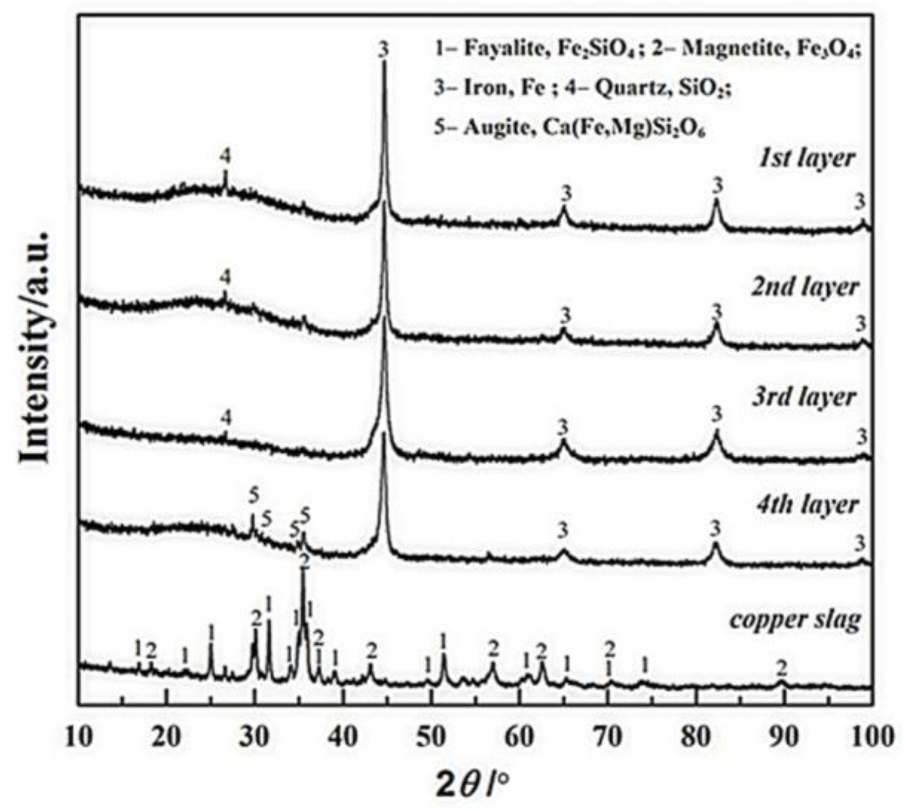
5.1. Analysis of the Mechanism of the Distribution Thickness (Pellets Layers)

In order to explore the mechanism of the effect of layers of the carbon-bearing pellets (thickness of layers) on the DR process, XRD analysis was conducted on the copper slag and the metallization pellets at different locations of a 4-layer distribution thickness. The details are shown in Figure 8. The first, the second, the third and the fourth layer, respectively, indicate the pellets from the upper (top) to the lower (bottom).
In Figure 8, four changes can be observed: (1) The phases of fayalite (Fe2SiO4) and magnetite (Fe3O4) do not exist anymore after DR in a RHF; (2) Differences in the major peak heights of metallized pellets from layer 1 to layer 4 mean differences in their Fe contents, namely, layer 1 > layer 2 > layer 3 > layer 4; (3) Occurrence of the diffraction peak values of the dissociate SiO2 in pellets layer 1, 2 and 3 indicates a complete and effective reduction, with all SiO2 released from the fayalite phase that is conducive to an increase in the iron recovery rate through the grinding and magnetic separation; (4) Apparent appearance of the diffraction peak of the impurities (augite Ca(Fe,Mg)Si2O6) in the metallization pellets of layer 4 also indirectly indicates that the reduction effect of the pellets in the distributed layer 4 is not as good as those in layer 1, 2 and 3.
Therefore, it can be concluded that the iron reduction of the pellets in a distribution thickness of three layers is comparatively more complete, which is beneficial for the iron recovery in the subsequent grinding/magnetic separation process.
Figure 9 shows the results of the analysis by using SEM and EDS conducted at different locations of the metallization pellets, with a, b, c, d respectively indicating layer 1, 2, 3 and 4. It can be clearly seen that the iron crystal chains are formed from iron agglomeration in layer 1, 2 and 3, which is conducive to iron recovery in subsequent grinding/magnetic separation operations. The pellets of layer 4, however, show scattered iron particles in the pellets, indicating a less effective reduction, with a lower iron recovery than those in the first three layers.

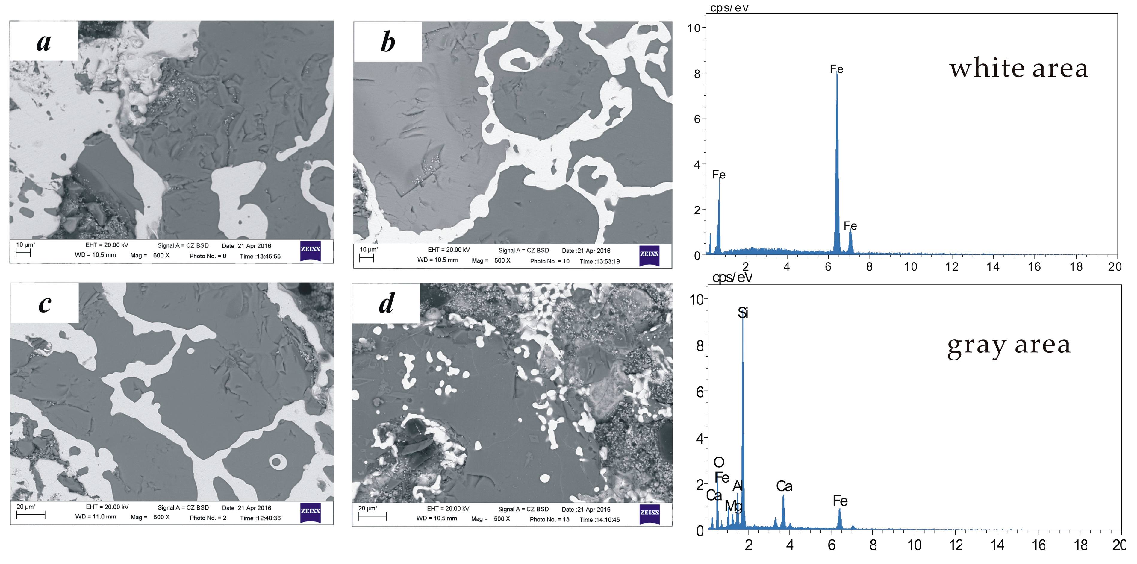
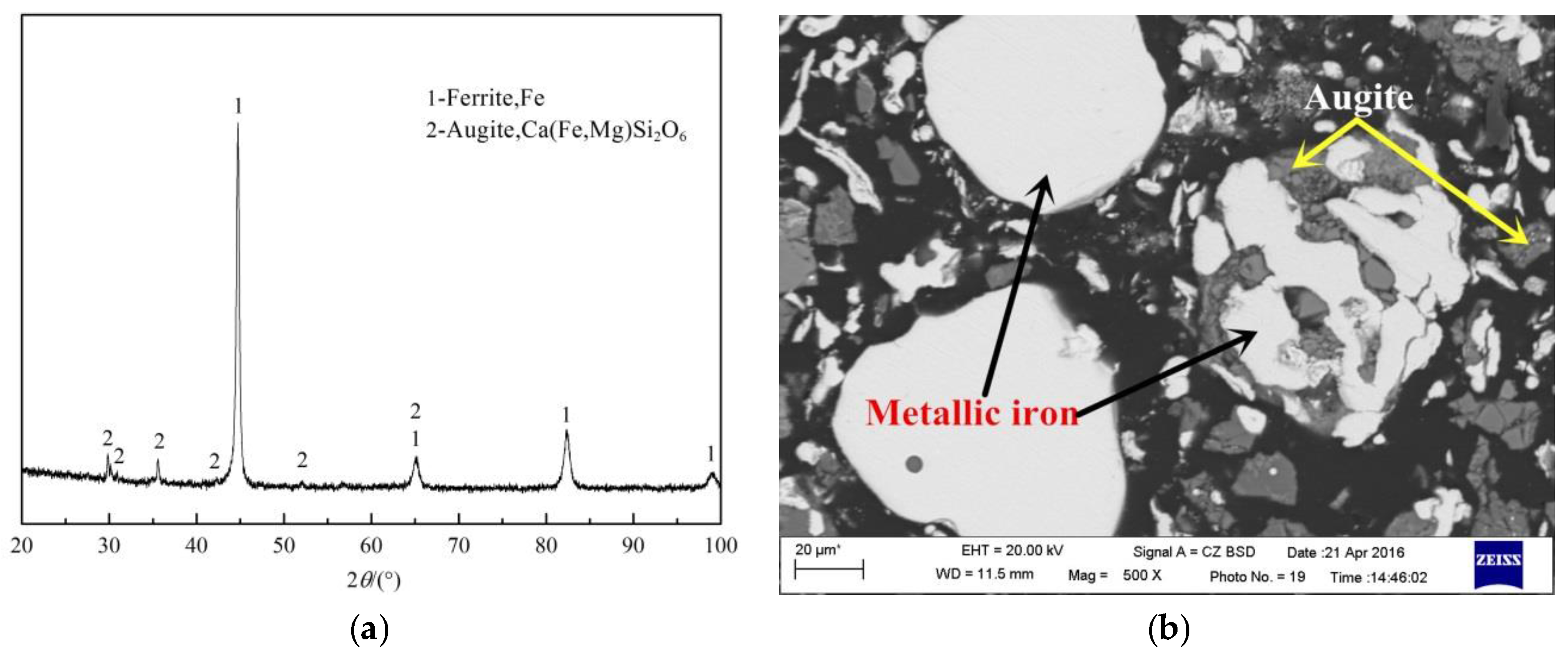
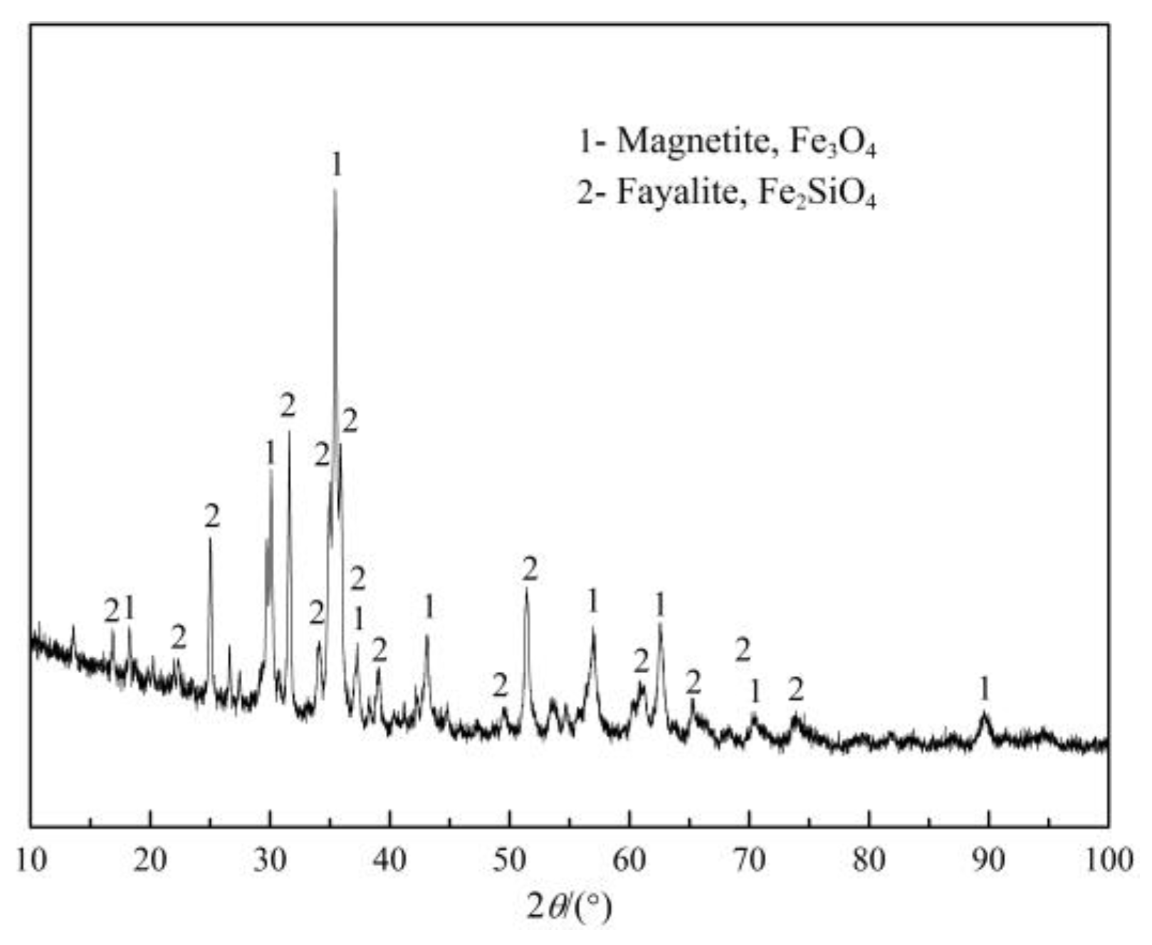
5.2. Product Analysis

The chemical analysis of the iron powder obtained from the pilot plant tests is shown in Table 2, and the chemical analysis of ZnO-rich dust obtained from the bag filter system is shown in Table 3. It can be seen that the metallic iron (MFe) accounts for the majority of the magnetically separated iron powder, with a metallization rate of 99.09%, and less contents of impurities such as sulfur and phosphorous, which is a good quality reduced iron powder. The zinc oxide content of the ZnO-rich dust, obtained from the bag filter system, is 68.53%, which can be a good raw material for zinc smelters.
Figure 10 is the XRD patterns and SEM image of the iron powder from the grinding/magnetic separation. It can be seen that iron in the iron powder obtained from the grinding/magnetic separation exhibits a high diffraction peak, with certain impurities in the pyroxene phase. The SEM image shows larger iron particles in the metallization iron powder from the grinding/magnetic separation, with certain impurity in the augite phase wrapped within.

6. Conclusions

(1)
Basic tests and pilot scale plant tests have been conducted on the discarded copper slag from a Chinese copper smelting plant, by adopting a direct reduction in a RHF and a subsequent grinding/magnetic separation process, from which optimal conditions are acquired as follows: the proportion of discarded copper slag, reduction coal, limestone and industrial sodium carbonates of 100:25:10:3, the reduction temperature of 1280 °C for the reduction time of 35 min, and the pellets in three layers (about 42 mm thick). The pilot-scale tests in a RHF have been carried out under such conditions and the obtained iron powder products have an iron grade of 90.35% with an iron recovery rate of 89.70%.
(2)
Analysis of the mechanism shows that fayalite and magnetite in the copper slag are reduced into metallic Fe in the direct reduction process, and the mass and heat transfer become stronger from the bottom layer to the top layer, exhibiting a higher diffraction peak. In addition, the iron in the metallization pellets turns into iron crystal chains from a dispersion state, resulting in a rising iron recovery rate.

Acknowledgments

This work was financially supported by Beijing Science and Technology Special Project (Grant No. Z151100001615027).

Author Contributions

Zhicheng Cao, Tichang Sun and XunXue conceived and designed the experiments; Zhicheng Cao and Zhanhua Liu performed the experiments; Zhicheng Cao and Tichang Sun analyzed the data; Zhicheng Cao wrote the paper.

Conflicts of Interest

The authors declare no conflict of interest.

References

  1. Jiang, P.G.; Wu, P.F.; Hu, X.J.; Zhou, G.Z. Current state and research of comprehensive utilization of copper slag, and proposal of new technology. China Min. Mag. 2015, 25, 76–77. [Google Scholar]
  2. Zhao, K.; Chen, X.L.; Qi, Y.H.; Zhen, C.L.; Shuai, X.F. Study on impact factors in recovering iron and copper from copper slag by carbon reduction. Environ. Eng. 2012, 30, 76–79. [Google Scholar]
  3. Zeng, J.L.; Xiao, K.M. Research on using dispersant agent to iron recovery in furnace slag. Nonferr. Met. Sci. Eng. 2011, 2, 71–73. [Google Scholar]
  4. Hu, G.; Xu, S.P.; Li, S.G. Steam gasification of apricot stones with olivine and dolomite as downstream catalysts. Fuel Process. Technol. 2006, 87, 375–382. [Google Scholar] [CrossRef]
  5. Yang, T.; Hu, J.H.; Wang, H.; Li, L. Enrichment of Fe3O4 by roasting the dilution copper slag from the electric furnace smelting. Chin. J. Process. Eng. 2011, 11, 613–619. [Google Scholar]
  6. Yuan, S.Q.; Dong, J.; Wang, C.; Wang, Z.J. Study on processes for comprehensive treatment of extractive copper tailings and nickel smelting slag. Chin. J. Rare Met. 2014, 38, 108–114. [Google Scholar]
  7. Mansoor, B.; Keneths, C. Electrical and electronic conductivity of CaO-SiO2-FeOx slags at various oxygen potentials: Part 1. Experimental results. Met. Mater. Trans. 2006, 37, 41–49. [Google Scholar]
  8. Li, Z.K.; Wen, Y.X.; Su, J. Directive reducing of iron minerals from copper slag with anthracite as reductant. Inorg. Chem. Ind. 2014, 46, 51–55. [Google Scholar]
  9. Wang, Y.; Zhu, R.; Guo, Y.G.; Zhou, M.; Guo, M.W.; Zhou, C.F. Experimental study on the copper slag reduction process. Nonferr. Met. Sci. Eng. 2014, 5, 61–67. [Google Scholar]
  10. Yang, H.F.; Jing, L.L.; Dang, C.G. Iron recovery from copper-slag with lignite-based direct reduction followed by magnetic separation. Chin. J. Nonferr. Met. 2011, 21, 1165–1170. [Google Scholar]
  11. Wang, S.; Ni, W.; Wang, C.L.; Li, D.Z.; Wang, H.Y. Study of deep reduction process for iron recovery from copper slag. Met. Mine 2014, 453, 156–160. [Google Scholar]
  12. Ge, X.F.; Xu, A.J.; He, D.F.; Wang, H.B.; Tian, N.Y. Experimental research on the tunnel kiln process for processing stainless steel dust. J. Univ. Sci. Technol. Beijing 2012, 34, 859–866. [Google Scholar]
  13. Wei, R.F.; Li, J.X.; Long, H.M.; Wang, P.; Shi, S.Q. Quantitative study on bonding behavior during reduction of carbon bearing pellets. J. Iron Steel Res. Int. 2014, 26, 13–16. [Google Scholar]
  14. Gao, J.T.; Zhou, C.F.; Zhu, R.; Liu, R.Z. Research on the heat supply of different sections in a rotary hearth furnace. J. Univ. Sci. Technol. Beijing 2014, 4, 110–116. [Google Scholar]
  15. She, X.F.; Wang, J.S.; Han, Y.H.; Zhang, X.X.; Xue, Q.G. Comprehensive mathematical model for direct reduction processes in rotary hearth furnaces. J. Univ. Sci. Technol. Beijing 2014, 35, 1580–1587. [Google Scholar]
Figure 1. XRD patterns of the received copper slag.
Minerals 06 00119 g001
Figure 2. Effect of reduction coal dosage on the DR process.
Minerals 06 00119 g002
Figure 3. Effect of limestone dosage on the DR process.
Minerals 06 00119 g003
Figure 4. Effect of industrial sodium carbonate dosage on the DR process.
Minerals 06 00119 g004
Figure 5. Effect of reduction temperature on the DR process.
Minerals 06 00119 g005
Figure 6. Effect of reduction time on the DR process.
Minerals 06 00119 g006
Figure 7. Effect of carbon-containing pellets layers on the DR process.
Minerals 06 00119 g007
Figure 8. XRD patterns of copper slag and metallization pellets.
Minerals 06 00119 g008
Figure 9. SEM images and EDS analysis results of the metallization pellets. (a) layer 1; (b) layer 2; (c) layer 3; (d) layer 4.
Minerals 06 00119 g009
Figure 10. XRD patterns (a) and SEM image (b) of the iron powder from the grinding/magnetic separation.
Minerals 06 00119 g010
Table 1. Chemical composition of discarded copper slag.
ElementsTFeFeOCuCaOMgOSiO2Al2O3Na2OK2OPbZnS
Content (wt %)40.7838.520.251.742.0833.202.290.400.610.511.350.19
Table 2. Chemical composition of obtained iron powder from grinding/magnetic separation.
ElementsTfeMfeCaOMgOSiO2Al2O3CuCMnPS
Content (wt %)91.0390.200.140.670.401.870.350.610.070.020.08
Table 3. Chemical composition of obtained ZnO rich dust.
ElementsTFeCaOMgOSiO2Al2O3K2ONa2OPbOZnOCSP
Content (wt %)1.840.843.211.470.600.540.1714.2168.530.113.540.13

