Abstract
Carbon materials derived from lignocellulosic biomass (LCB) precursors have emerged as sustainable and versatile candidates, exhibiting outstanding properties for energy storage applications. This study presents an innovative and cost-efficient approach to produce graphitic carbon from an LCB precursor (pinecone) using an optimized hydrothermal treatment process followed by carbonization and graphitization. The developed pinecone-derived graphitic carbon (PDGC) was analyzed using X-ray diffraction (XRD), transmission electron microscopy (TEM) and scanning electron microscopy (SEM). XRD analysis confirmed the formation of a graphitic phase, indicated by a sharp and intense (002) peak, decreased interplanar spacing (d002), increased crystallite size (Lc~20.4 nm), and a high degree of graphitization (g~0.7), closely aligning with the characteristics of pure graphite. Additionally, TEM and SEM micrographs revealed a flake-like morphology with well-defined, continuous, and extended graphitic layers within the PDGC structure. The distinctive structural attributes of the developed material position it as a promising candidate for batteries and capacitors, while also serving as a model for converting LCB into advanced carbon materials.
1. Introduction
The rising demand for efficient energy storage solutions underscores the necessity for advanced electrode materials. Prominent materials in this field include graphene, graphite, carbon nanotubes, silicon–carbon composites, transition metal oxides, MXenes, and hybrid carbon-based materials [1,2,3,4,5,6,7,8,9]. Due to the distinctive structural characteristics and excellent electrochemical behavior, carbon-based materials have become a focal point of research [10,11]. Various forms of carbon, such as carbon nanotubes, porous carbon nanofibers, graphene, hard carbons and graphitic carbons, have been rigorously investigated for their impressive features, including large surface area, tunable pore structures, outstanding conductivity, and excellent physicochemical stability [10,12,13,14]. Despite this progress, the majority of carbon material synthesis methods still rely heavily on unsustainable fossil fuel derivatives, such as byproducts from petroleum refining and coal-tar, which involve energy-intensive and expensive processes [15,16,17,18].
In this context, LCB offers a promising and renewable feedstock for the production of advanced carbon materials. They are typically sourced from plant-based materials, such as byproducts of agriculture, remnants from forestry operations, and specially cultivated energy-rich crops [19], making them abundant and cost-effective precursors for carbon production. LCB, composed of cellulose (C6H10O5)x, hemicelluloses (C5H8O4)m and lignin [C9H10O3·(OCH3)0.9–1.7]n in varying proportions depending on the source, holds great potential for conversion into high-value carbon-based materials [20,21]. Various carbon architectures, including activated carbons [22], carbon spheres [23,24], and carbon molecular sieves [21], have been successfully synthesized from a range of lignocellulosic biomass sources [25,26,27]. The majority of these carbon structures display highly disordered, non-graphitic characteristics, which restrict their utility in energy storage applications. This is primarily due to the intricate composition and resistant nature of LCB, which poses significant challenges for its effective conversion into graphitic carbon materials. In particular, lignin present in LCB, despite being aromatic and carbon-rich, tends to form disordered or turbostratic carbon structures during pyrolysis, making the synthesis of highly ordered graphitic carbon challenging without advanced processing techniques [28]. Despite the promising potential of LCB, attempts to produce highly ordered graphitic carbons have been relatively limited. Graphitic materials have attracted considerable interest due to their exceptional electrical conductivity, thermal stability, and well-defined layered structures, which make them highly suitable for advanced energy storage applications [29,30,31]. These graphitic carbons feature a honeycomb lattice structure composed of sp2-hybridized carbon atoms, closely mirroring the arrangement found in natural graphite [29].
In order to prepare carbon structures from LCB, numerous methods have been used, such as the templating process [32], direct pyrolysis [33], catalytic graphitization [34,35], chemical vapor deposition [36], high-temperature graphitization [27], and hydrothermal carbonization [37,38]. Among these approaches, a combined method involving hydrothermal carbonization followed by high-temperature graphitization has emerged as a particularly promising technique for producing graphitic carbon. This approach effectively integrates mild hydrothermal conditions with high-temperature treatment to produce highly ordered graphitic carbon, offering controlled morphology and enhanced material properties (crystallite size, stacking height, and degree of graphitization) for energy storage applications.
Building on the potential of LCB-derived carbons, this study focuses on the synthesis of graphitic carbon from pinecones, a renewable and widely available biomass resource. The high lignin content in pinecones may facilitate the formation of graphitic domains under controlled hydrothermal and thermal treatment conditions, highlighting their potential for generating high-quality carbon and providing valuable insights for optimizing other lignocellulosic feedstocks in advanced material development [39,40]. Despite this promise, their use in fabricating highly ordered graphitic carbons has been largely unexplored, highlighting the novelty and importance of this work in advancing sustainable approaches to graphitic carbon synthesis. Therefore, in this study, high-quality graphitic carbon from pinecone biomass was produced through an optimized hydrothermal pretreatment process followed by carbonization and graphitization. The crystallite parameters and morphology of the resulting graphitic carbon were examined using XRD, TEM, and SEM and were compared with natural graphite. This study contributes to materials science and engineering by highlighting the potential of sustainable feedstocks to produce eco-friendly graphitic carbons, which hold promise for energy storage applications.
2. Materials and Methods
2.1. Materials
Pinecones from American pine tree (Pinus strobus) were collected locally from State College (Pennsylvania, PA, USA). Hydrochloric acid (37%, ACS reagent) was purchased from Sigma Aldrich, Inc., St. Louis, MO, USA. The pinecone biomass was then utilized to synthesize the graphitic carbon.
2.2. Methods
2.2.1. Development of Pinecone-Derived Graphitic Carbon
To prepare highly ordered graphitic carbon, the pinecones were first thoroughly washed with deionized water to remove impurities, followed by drying at 110 °C for 24 h. The dried material was then ground into fine powder and sieved (with 850 μm sieve size) to achieve a uniform particle size. The powdered biomass was mixed with deionized water at a 1:10 (w/v) ratio and transferred to a Teflon-lined hydrothermal reactor. The reactor was then heated to 200 °C for 24 h under a pressure of 35 bar [41]. After cooling, the hydrochar was collected through filtration, rinsed thoroughly with deionized water and ethanol, and subsequently dried at 100 °C. Further, we enclosed 10 g of hydrochar in brass-foil and inserted into the sealed tubing reactor. For the carbonization at 500 °C for 4 h in inert environment, we placed the reactor into the air-fluidized sand bath. Following carbonization, the sample underwent graphitization, where it was heated to 2500 °C for 1 h in an argon atmosphere. The graphitization process was carried out using a Series 45 Centorr Vacuum Industries furnace, where graphite served as the heating element. Prior to heating, the furnace underwent three stages of vacuum evacuation, vacuuming to below 100 mTorr, and subsequently argon backfilling to purge residual air. To uphold inert conditions, argon gas was continuously purged throughout the graphitization stage. The final step involved washing the product with hydrochloric acid to remove remaining impurities, followed by thorough rinsing with deionized water until it reached a neutral pH. The material was then dried to obtain highly ordered graphitic carbon. A visual schematic of the PDGC preparation method is provided in Figure 1.
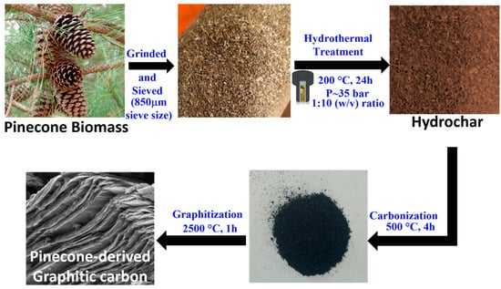
Figure 1.
Illustration outlining the development process of graphitic carbon from pinecone feedstock.
2.2.2. Characterization of Graphitic Carbon
The bulk graphitic quality of the graphitized carbon sample was assessed using Powder XRD, while TEM and SEM were employed to analyze its morphology and lamellar structure.
X-Ray Diffraction Analysis
A Malvern PANalytical Empyrean diffractometer employed with Cu radiation source of λ = 1.54 Å, paraxial focus optics, PIXcel 3D X-ray detector was utilized for XRD analysis. The angular range of 2θ = 5° to 80° was used to collect XRD spectra, which was further deconvoluted and quantified using MDI JADE software, selecting best fit with the minimal residual values for accurate analysis of data. To ensure accuracy, we accounted for instrumental broadening by measuring the diffraction pattern of a well-crystallized standard material (such as silicon) under the same experimental conditions. The observed peak broadening was then corrected using the following equation:
where is the experimentally observed FWHM, and is the FWHM obtained from the instrumental standard. The corrected peak width was then used to estimate the crystallite size using the Scherrer formula:
where L is the crystallite size, K is the shape factor, λ is the X-ray wavelength, and θ is the Bragg angle of the peak. To determine the in-plane crystallite diameter (La) and stacking height (Lc), the Scherrer equation was applied using Ka and Kc values of 1.84 and 0.89, respectively [42].
Transmission Electron Microscopy Imaging
The FEI Talos™ model F200X Scanning/TEM, featuring a field-emission gun source with a 0.12 nm resolution, was utilized for TEM analysis. For TEM sample preparation, a small amount of the powdered material was sonicated in ethanol and drop-cast onto a 300-mesh C/Cu lacey TEM grid. The microscope operated at an acceleration voltage of 200 kV, capturing images at magnifications ranging from 10 to 500 kX. Moreover, the local crystallinity of the sample was analyzed using Fast-Fourier Transform (FFT) analysis.
Scanning Electron Microscopy Imaging
SEM imaging was carried out using an Apreo system. For imaging, a small amount of the sample was mounted on a pin stub holder with carbon tape attached to it. SEM images were acquired at an acceleration voltage of 7 kV, with the working distance adjusted between 11 mm and 7 mm.
3. Results and Discussion
The synthesis route, as illustrated in Figure 1, details the gradual conversion of pinecone biomass into graphitic carbon via a series of steps, including grinding, sieving, hydrothermal treatment, carbonization, and graphitization. The process begins with the preparation of biomass to achieve a uniform particle size, followed by hydrothermal treatment at 200 °C for 24 h, which enhances the structural properties and preconditions the material for further carbonization. The hydrothermal pretreatment enhances carbon yield and graphitic domain formation by partially decomposing cellulose, hemicellulose and restructuring lignin before carbonization. The optimized conditions (200 °C, 24 h, 35 bar) facilitate hydrolysis, dehydration, and decarboxylation, improving aromatization and reducing oxygen content [43]. Additionally, the autogenous pressure prevents excessive porosity, ensuring a dense and uniform carbon structure, making this approach more effective than conventional methods. Moreover, subjecting the hydrochar to carbonization (500 °C, 4 h) in an inert environment results in the formation of an amorphous carbon-dense structure, while subsequent graphitization at 2500 °C for 1 h achieves a highly ordered graphitic structure. The produced PDGC sample underwent characterization to assess its structural features, such as crystallite dimensions, lattice characteristics, and morphological attributes, which are elaborated in the following sections.
3.1. Bulk Study of PDGC Material
The XRD pattern and deconvoluted diffractogram of PDGC and natural graphite are illustrated in Figure 2. A sharp and intense (002) peak is observed at 26.3° (Figure 2a,b), resembling that of pure graphite [44,45]. This indicates small d002 and improved graphitic quality following the graphitization process, as compared to other graphitic carbon materials derived from LCB sources, as reported in Refs. [46,47,48]. Here, the graphitic quality refers to the degree of structural order and crystallinity in graphitic carbon materials. Furthermore, the deconvoluted XRD pattern of PDGC (Figure 2d) in the 40–50° range reveals three distinct peaks similar to natural graphite. The two prominent peaks correspond to the (100) and (101) reflection planes of graphitic carbon, while the third (Figure 2c and inset of Figure 2d), which is typically weak and less intense, arises from the (102) reflection, likely due to in-plane stacking variations or partial turbostratic disorder, influencing the diffraction pattern [49]. A comparison of lattice parameters between PDGC and natural graphite, derived from the deconvoluted XRD diffractogram (Figure 2d), is provided in Table 1. The d002 for PDGC was determined to be 3.37 Å, slightly larger than that of natural graphite (3.35 Å) (as reported in Ref. [50]), suggesting the presence of minor structural imperfections or turbostratic arrangements within its graphitic planes. Additionally, the Lc value calculated from the (002) peak was 20.4 nm for PDGC, slightly lower than the 24.6 nm observed for natural graphite, reflecting smaller and less ordered stack sizes. Moreover, the Seeha and Pavloic relation was applied to calculate the graphitization degree (g) (Equation (3)) [51].
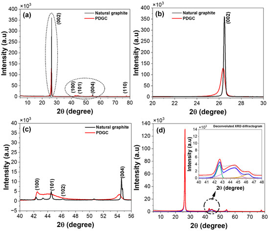
Figure 2.
(a) XRD pattern of PDGC and natural graphite, (b,c) extended view of XRD diffractograms of PDGC and natural graphite in different 2θ degree range, and (d) deconvoluted diffractogram of PDGC (inset: extended view of deconvoluted diffractogram).

Table 1.
Lattice parameters obtained from deconvoluted XRD spectra of PDGC.
As a critical parameter, the g-value in carbon materials quantifies the graphitization level, providing insight into its resemblance to pure graphite. For PDGC, the value of g, calculated from the d002, was approximately 0.7, slightly lower than the ideal value of 1 for natural graphite, indicating a marginally lower but still substantial level of graphitic ordering. Despite these differences, the high Lc and g values confirm the superior graphitic characteristics of PDGC.
3.2. Morphological and Microstructural Analysis
The morphology of the synthesized PDGC was analyzed using TEM imaging. Figure 3 illustrates both low-resolution and high-resolution TEM (HRTEM) images, revealing a layered and flaky structure. The images depict thin, overlapping sheets and layers characteristic of graphitic structures with well-aligned planes. The extracted d002 of 0.337 nm closely matches the theoretical interlayer spacing of natural graphite (002) planes, indicating a high degree of graphitization (as reported in Ref. [44]). Additionally, the presence of slightly curved and wrinkled regions suggests partially ordered graphitic domains, likely formed during the graphitization process. High-resolution images, particularly in Figure 3b,c, highlight well-ordered graphitic layers, confirming the material’s high crystallinity. However, a minor presence of non-graphitic content was also found (refer to Figure S1). In Figure 3d, the FFT pattern exhibited bright, well-defined spots along with concentric rings around the central region, signifying a polycrystalline nature formed by the multi-crystallite diffraction. These findings align with the XRD results detailed in Section 3.1, reinforcing the confirmation of the graphitic phase in the PDGC sample.
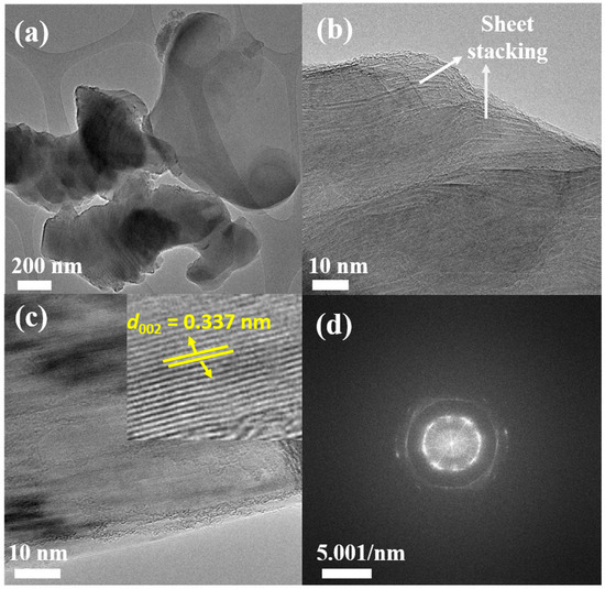
Figure 3.
TEM images of PDGC highlighting its graphitic morphology at different magnifications: (a,b) display a flaky, layered structure resembling natural graphite, (c) structured graphitic layers, with the inset revealing a 0.337 nm lattice spacing, characteristic of the (002) planes in graphite, and (d) its associated FFT pattern.
Furthermore, SEM analysis was performed to study the microstructural features of the PDGC material. As shown in Figure 4, the material exhibits a flaky, layered morphology, resembling that of natural graphite (as described in Ref. [52]). This layered structure may facilitate efficient ion intercalation and deintercalation during charge and discharge cycles, which could enhance cycle life and stability. The structural features of the developed carbon, such as high crystallinity, well-defined graphitic layers, and a layered morphology, show its great viability as an electrode material for next-generation batteries and capacitors, making it a promising candidate for advanced energy storage systems. Furthermore, it also demonstrates that pinecone biomass serves as a model for other LCBs, showcasing an efficient synthetic route for producing high-quality carbons.
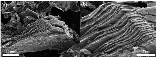
Figure 4.
(a,b) SEM images of PDGC showing a flake-like morphology similar to natural graphite (as reported in Ref. [52]).
3.3. Graphitization Mechanism for the Formation of Pinecone-Derived Graphitic Carbon
The possible graphitization mechanism of LCB into graphitic carbon follows a multi-step process, involving dehydration, decarboxylation, carbonization, and graphitization, as shown in Figure 5. Initially, lignocellulosic biomass, composed of cellulose, hemicellulose, and lignin, undergoes thermal decomposition, leading to the removal of hydroxyl (-OH) and carboxyl (-COOH) functional groups through dehydration and decarboxylation reactions. These reactions eliminate H2O and CO2, reducing the oxygen content and increasing the carbon concentration [43,53]. As the temperature rises, the breakdown of biopolymers results in the formation of amorphous carbon structures with randomly oriented aromatic clusters [43]. With further heating at 500 °C, these clusters start to align, forming small graphitic-like domains. At high temperatures (~2500 °C), the amorphous carbon undergoes significant structural reorganization, leading to the development of well-ordered graphitic layers with enhanced crystallinity.
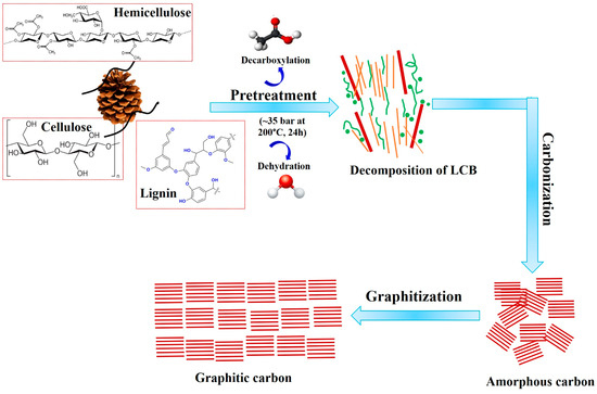
Figure 5.
Graphitization mechanism for the conversion of LCB into graphitic carbon.
4. Conclusions
This research extensively analyzed the process of graphitic carbon formation from sustainable pinecone biomass using a hydrothermal pretreatment followed by carbonization and graphitization. The structural parameters, morphology, and microstructure of the developed PDGC were examined using XRD, TEM and SEM. The XRD results confirmed the formation of a graphitic phase, evidenced by a sharp and intense (002) peak, reduced d002 value, a larger crystallite size (Lc~20.4 nm), and a high degree of graphitization (g~0.7) compared to other graphitic carbon materials derived from LCB sources, and closely resembling pure graphite. In addition, TEM and HRTEM analysis corroborated these findings, revealing a flake-like morphology with well-defined, long, and continuous graphitic lamellae within the PDGC structure. Similarly, SEM analysis revealed a layered, lamellar structure comparable to natural graphite. These characteristics establish PDGC as a highly promising electrode material for batteries and capacitors, showcasing its strong potential for energy storage applications. Moreover, this study paves the way for leveraging pinecone biomass as a model system to convert lignocellulosic feedstocks into advanced carbon materials optimized for energy solutions.
Supplementary Materials
The following supporting information can be downloaded at: https://www.mdpi.com/article/10.3390/min15030262/s1, Figure S1: (a–d) TEM images of PDGC highlighting the presence of non-graphitic components.
Author Contributions
B.A.: Conceptualization, data curation, investigation, methodology, writing—original draft. S.O.: Writing—original draft. R.L.V.W.: Supervision, project administration, resources, funding, validation, review. All authors have read and agreed to the published version of the manuscript.
Funding
Grateful acknowledgment is extended for the support provided to Bindu and this research through the Dean’s Distinguished Postdoctoral Scholar Award, granted by the College of Earth and Mineral Sciences. This material is also based on work supported by the National Science Foundation under Grant No. DMR-2306042.
Data Availability Statement
Data are contained within the article and Supplementary Materials.
Acknowledgments
Materials Research Institute at Penn State facilitated TEM, XRD, and SEM analyses for this study.
Conflicts of Interest
The authors declare no conflicts of interest.
References
- Huang, Y.; Tang, Z.; Zhou, S.; Wang, H.; Tang, Y.; Sun, D.; Wang, H. Renewable waste biomass-derived carbon materials for energy storage. J. Phys. D Appl. Phys. 2022, 55, 313002. [Google Scholar] [CrossRef]
- Antil, B.; Kumar, L.; Das, M.R.; Deka, S. N-doped graphene modulated N-rich carbon nitride realizing a promising all-solid-state flexible supercapacitor. J. Energy Storage 2022, 52, 104731. [Google Scholar] [CrossRef]
- Yan, D.; Song, L.; Kang, F.; Mo, X.; Lv, Y.; Sun, J.; Tang, H.; Zhou, X.; Zhang, Q. In Situ Growth of Covalent Organic Frameworks on Carbon Nanotubes for High-Performance Potassium-Ion Batteries. Angew. Chem. 2025, e202422851. [Google Scholar] [CrossRef]
- Yuan, Y.; Hu, R.; Wang, W.; Wang, Y.; Zhang, T.; Wang, Z. Design and fabrication of high-performance multilayer silicon-carbon composite anodes for lithium-ion batteries via femtosecond laser. J. Energy Storage 2025, 110, 115362. [Google Scholar] [CrossRef]
- Olhan, S.; Behera, B.K. Development of GNP nanofiller based textile structural composites for enhanced mechanical, thermal, and viscoelastic properties for automotive components. Adv. Compos. Hybrid. Mater. 2024, 7, 25. [Google Scholar] [CrossRef]
- Olhan, S.; Antil, B.; Behera, B.K. Synergistic effect of different high-performance fibers on the microstructural evolution and mechanical performance of novel hybrid metal matrix composites produced via friction stir processing for automotive applications. Proc. Inst. Mech. Eng. Part B J. Eng. Manuf. 2024, 239, 236–249. [Google Scholar] [CrossRef]
- Chen, G.; Wang, M.; Jiao, M.; Kong, X.; Zhao, L. Rapid Joule-heating synthesis of oxide nanoparticles on carbon cloth as electrodes for supercapacitors. J. Power Sources 2025, 629, 235963. [Google Scholar] [CrossRef]
- Bhat, Y.; Adeosun, W.A.; Prenger, K.; Samad, Y.A.; Liao, K.; Naguib, M.; Mao, S.; Qurashi, A. Frontiers of MXenes-based hybrid materials for energy storage and conversion applications. Adv. Compos. Hybrid. Mater. 2025, 8, 52. [Google Scholar] [CrossRef]
- Olhan, S.; Khatkar, V.; Behera, B.K. Mechanical Behavior of Natural Fiber Based 3D woven Structural Composites for Automotive applications. In Proceedings of the 47th Textile Research Symposium (TRS), Liberec, Czech Republic, 19–21 June 2019; pp. 65, 120. [Google Scholar]
- Wang, J.; Zhang, X.; Li, Z.; Ma, Y.; Ma, L. Recent progress of biomass-derived carbon materials for supercapacitors. J. Power Sources 2020, 451, 227794. [Google Scholar] [CrossRef]
- Zhai, Z.; Zhang, L.; Du, T.; Ren, B.; Xu, Y.; Wang, S.; Miao, J.; Liu, Z. A review of carbon materials for supercapacitors. Mater. Des. 2022, 221, 111017. [Google Scholar] [CrossRef]
- Wang, Q.; Yan, J.; Fan, Z. Carbon materials for high volumetric performance supercapacitors: Design, progress, challenges and opportunities. Energy Environ. Sci. 2016, 9, 729–762. [Google Scholar] [CrossRef]
- Borenstein, A.; Hanna, O.; Attias, R.; Luski, S.; Brousse, T.; Aurbach, D. Carbon-based composite materials for supercapacitor electrodes: A review. J. Mater. Chem. A 2017, 5, 12653–12672. [Google Scholar] [CrossRef]
- Zhang, L.L.; Zhao, X.S. Carbon-based materials as supercapacitor electrodes. Chem. Soc. Rev. 2009, 38, 2520. [Google Scholar] [CrossRef]
- Hoang, V.C.; Hassan, M.; Gomes, V.G. Coal derived carbon nanomaterials—Recent advances in synthesis and applications. Appl. Mater. Today 2018, 12, 342–358. [Google Scholar] [CrossRef]
- Li, S.; Jin, B.; Zhai, X.; Li, H.; Jiang, Q. Review of Carbon Materials for Lithium-Sulfur Batteries. ChemistrySelect 2018, 3, 2245–2260. [Google Scholar] [CrossRef]
- Lee, S.-M.; Kang, D.-S.; Roh, J.-S. Bulk graphite: Materials and manufacturing process. Carbon Lett. 2015, 16, 135–146. [Google Scholar] [CrossRef]
- Singh, M.; Vander Wal, R.L. Carbon Composites—Graphene-Oxide-Catalyzed Sugar Graphitization. C 2022, 8, 15. [Google Scholar] [CrossRef]
- Chew, J.J.; Doshi, V. Recent advances in biomass pretreatment—Torrefaction fundamentals and technology. Renew. Sustain. Energy Rev. 2011, 15, 4212–4222. [Google Scholar] [CrossRef]
- Morgan, H.M.; Bu, Q.; Liang, J.; Liu, Y.; Mao, H.; Shi, A.; Lei, H.; Ruan, R. A review of catalytic microwave pyrolysis of lignocellulosic biomass for value-added fuel and chemicals. Bioresour. Technol. 2017, 230, 112–121. [Google Scholar] [CrossRef]
- Mohamed, A.R.; Mohammadi, M.; Darzi, G.N. Preparation of carbon molecular sieve from lignocellulosic biomass: A review. Renew. Sustain. Energy Rev. 2010, 14, 1591–1599. [Google Scholar] [CrossRef]
- Kumar Mishra, R.; Singh, B.; Acharya, B. A comprehensive review on activated carbon from pyrolysis of lignocellulosic biomass: An application for energy and the environment. Carbon Resour. Convers. 2024, 7, 100228. [Google Scholar] [CrossRef]
- Khan, T.A.; Saud, A.S.; Jamari, S.S.; Rahim, M.H.A.; Park, J.-W.; Kim, H.-J. Hydrothermal carbonization of lignocellulosic biomass for carbon rich material preparation: A review. Biomass Bioenergy 2019, 130, 105384. [Google Scholar] [CrossRef]
- Olhan, S.; Antil, B.; Behera, B.K. Repair technologies for structural polymeric composites: An automotive perspective. Compos. Struct. 2025, 352, 118711. [Google Scholar] [CrossRef]
- Titirici, M.-M.; White, R.J.; Brun, N.; Budarin, V.L.; Su, D.S.; del Monte, F.; Clark, J.H.; MacLachlan, M.J. Sustainable carbon materials. Chem. Soc. Rev. 2015, 44, 250–290. [Google Scholar] [CrossRef]
- Luo, X.; Chen, S.; Hu, T.; Chen, Y.; Li, F. Renewable biomass-derived carbons for electrochemical capacitor applications. SusMat 2021, 1, 211–240. [Google Scholar] [CrossRef]
- Antil, B.; Elkasabi, Y.; Strahan, G.D.; Vander Wal, R.L. Development of graphitic and non-graphitic carbons using different grade biopitch sources. Carbon 2025, 232, 119770. [Google Scholar] [CrossRef]
- Yu, S.; Wang, L.; Li, Q.; Zhang, Y.; Zhou, H. Sustainable carbon materials from the pyrolysis of lignocellulosic biomass. Mater. Today Sustain. 2022, 19, 100209. [Google Scholar] [CrossRef]
- Harris, P.J.F. New Perspectives on the Structure of Graphitic Carbons. Crit. Rev. Solid State Mater. Sci. 2005, 30, 235–253. [Google Scholar] [CrossRef]
- Sharma, S. Glassy Carbon: A Promising Material for Micro- and Nanomanufacturing. Materials 2018, 11, 1857. [Google Scholar] [CrossRef]
- Franklin, R.E. The structure of graphitic carbons. Acta Crystallogr. 1951, 4, 253–261. [Google Scholar] [CrossRef]
- Joo, J.B.; Kim, P.; Kim, W.; Kim, J.; Kim, N.D.; Yi, J. Simple preparation of hollow carbon sphere via templating method. Curr. Appl. Phys. 2008, 8, 814–817. [Google Scholar] [CrossRef]
- Tam, N.T.M.; Liu, Y.-G.; Bashir, H.; Zhang, P.; Liu, S.-B.; Tan, X.; Dai, M.-Y.; Li, M.-F. Synthesis of Porous Biochar Containing Graphitic Carbon Derived From Lignin Content of Forestry Biomass and Its Application for the Removal of Diclofenac Sodium From Aqueous Solution. Front. Chem. 2020, 8, 274. [Google Scholar] [CrossRef]
- Gai, L.; Li, J.; Wang, Q.; Tian, R.; Li, K. Evolution of biomass to porous graphite carbon by catalytic graphitization. J. Environ. Chem. Eng. 2021, 9, 106678. [Google Scholar] [CrossRef]
- Lower, L.; Dey, S.C.; Vook, T.; Nimlos, M.; Park, S.; Sagues, W.J. Catalytic Graphitization of Biocarbon for Lithium-Ion Anodes: A Minireview. ChemSusChem 2023, 16, e202300729. [Google Scholar] [CrossRef]
- Fathy, N.A. Carbon nanotubes synthesis using carbonization of pretreated rice straw through chemical vapor deposition of camphor. RSC Adv. 2017, 7, 28535–28541. [Google Scholar] [CrossRef]
- Pan, Q.; Li, B.; Liu, S.; Yang, Y.; Tang, X.; Liu, H.; Huang, R.; Wang, J. Flower-like graphitic carbon derived from biomass for anode of potassium ion battery. Chem. Eng. Sci. 2025, 304, 121043. [Google Scholar] [CrossRef]
- Demir, M.; Kahveci, Z.; Aksoy, B.; Palapati, N.K.R.; Subramanian, A.; Cullinan, H.T.; El-Kaderi, H.M.; Harris, C.T.; Gupta, R.B. Graphitic Biocarbon from Metal-Catalyzed Hydrothermal Carbonization of Lignin. Ind. Eng. Chem. Res. 2015, 54, 10731–10739. [Google Scholar] [CrossRef]
- Trifol, J.; Marin Quintero, D.C.; Moriana, R. Pine Cone Biorefinery: Integral Valorization of Residual Biomass into Lignocellulose Nanofibrils (LCNF)-Reinforced Composites for Packaging. ACS Sustain. Chem. Eng. 2021, 9, 2180–2190. [Google Scholar] [CrossRef]
- Creteanu, A.; Lungu, C.N.; Lungu, M. Lignin: An Adaptable Biodegradable Polymer Used in Different Formulation Processes. Pharmaceuticals 2024, 17, 1406. [Google Scholar] [CrossRef]
- Kongpanya, J.; Hussaro, K.; Teekasap, S. Influence of Reaction Temperature and Reaction Time on Product from Hydrothermal Treatment of Biomass Residue. Am. J. Environ. Sci. 2014, 10, 324–335. [Google Scholar] [CrossRef]
- Patterson, A.L. The Scherrer Formula for X-Ray Particle Size Determination. Phys. Rev. 1939, 56, 978–982. [Google Scholar] [CrossRef]
- Rogalinski, T.; Ingram, T.; Brunner, G. Hydrolysis of lignocellulosic biomass in water under elevated temperatures and pressures. J. Supercrit. Fluids 2008, 47, 54–63. [Google Scholar] [CrossRef]
- Franklin, R.E. Crystallite growth in graphitizing and non-graphitizing carbons. Proc. R. Soc. Lond. Ser. A Math. Phys. Sci. 1951, 209, 196–218. [Google Scholar]
- Alcaraz, L.; Díaz-Guerra, C.; Calbet, J.; López, M.L.; López, F.A. Obtaining and Characterization of Highly Crystalline Recycled Graphites from Different Types of Spent Batteries. Materials 2022, 15, 3246. [Google Scholar] [CrossRef]
- Sun, J.; Sun, Y.; Oh, J.A.S.; Gu, Q.; Zheng, W.; Goh, M.; Zeng, K.; Cheng, Y.; Lu, L. Insight into the structure-capacity relationship in biomass derived carbon for high-performance sodium-ion batteries. J. Energy Chem. 2021, 62, 497–504. [Google Scholar] [CrossRef]
- Kumar, U.; Wu, J.; Sharma, N.; Sahajwalla, V. Biomass Derived High Areal and Specific Capacity Hard Carbon Anodes for Sodium-Ion Batteries. Energy Fuels 2021, 35, 1820–1830. [Google Scholar] [CrossRef]
- Kim, Y.S.; Hanif, A.; Song, H.; Kim, S.; Cho, Y.; Ryu, S.-K.; Kim, H.G. Wood-Derived Graphite: A Sustainable and Cost-Effective Material for the Wide Range of Industrial Applications. Crystals 2024, 14, 309. [Google Scholar] [CrossRef]
- Oka, H.; Setoyama, N.; Matsuhara, S. Gas adsorption analysis for quantifying the edge sites of graphite. Carbon 2024, 230, 119664. [Google Scholar] [CrossRef]
- Popova, A.N. Crystallographic analysis of graphite by X-Ray diffraction. Coke Chem. 2017, 60, 361–365. [Google Scholar] [CrossRef]
- Seehra, M.S.; Pavlovic, A.S. X-Ray diffraction, thermal expansion, electrical conductivity, and optical microscopy studies of coal-based graphites. Carbon 1993, 31, 557–564. [Google Scholar] [CrossRef]
- Montagna, L.S.; Fim, F.d.C.; Galland, G.B.; Basso, N.R.d.S. Synthesis of Poly(propylene)/Graphite Nanocomposites by in Situ Polymerization. Macromol. Symp. 2011, 299–300, 48–56. [Google Scholar] [CrossRef]
- Tekin, K.; Karagöz, S.; Bektaş, S. A review of hydrothermal biomass processing. Renew. Sustain. Energy Rev. 2014, 40, 673–687. [Google Scholar] [CrossRef]
Disclaimer/Publisher’s Note: The statements, opinions and data contained in all publications are solely those of the individual author(s) and contributor(s) and not of MDPI and/or the editor(s). MDPI and/or the editor(s) disclaim responsibility for any injury to people or property resulting from any ideas, methods, instructions or products referred to in the content. |
© 2025 by the authors. Licensee MDPI, Basel, Switzerland. This article is an open access article distributed under the terms and conditions of the Creative Commons Attribution (CC BY) license (https://creativecommons.org/licenses/by/4.0/).