Article

Evolution of a Late Carboniferous Fluvio-Lacustrine System in an Endorheic Basin: Multiproxy Insights from the Ludwikowice Formation, Intra-Sudetic Basin (SW Poland, NE Bohemian Massif)

by
Aleksander Kowalski
1,*,
Jolanta Dąbek-Głowacka
2,3,*,
Grzegorz J. Nowak
1,
Anna Górecka-Nowak
4,
Urszula Wyrwalska
1,
Magdalena Furca
1 and
Patrycja Wójcik-Tabol
3
1
Polish Geological Institute−National Research Institute, Lower Silesia Branch, Al. Jaworowa 19, 50-122 Wrocław, Poland
2
Doctoral School of Exact and Natural Sciences, Jagiellonian University, Prof. St. Łojasiewicza 11, 30-348 Kraków, Poland
3
Institute of Geological Sciences, Jagiellonian University, Gronostajowa 3a, 30-387 Kraków, Poland
4
Institute of Geological Sciences, University of Wrocław, pl. Maxa Borna 9, 52-204 Wrocław, Poland
*
Authors to whom correspondence should be addressed.
Minerals 2025, 15(10), 1077; https://doi.org/10.3390/min15101077
Submission received: 11 September 2025 / Revised: 6 October 2025 / Accepted: 9 October 2025 / Published: 15 October 2025
(This article belongs to the Special Issue Deep-Time Source-to-Sink in Continental Basins)

Abstract

Fluvio-lacustrine systems are highly dynamic continental environments, often developing in tectonically controlled, endorheic basins where sedimentation reflects the interplay of fluvial processes, lake-level fluctuations, climate, and subsidence. The main aim of this paper is to reconstruct the depositional architecture and paleogeographic evolution of the Ludwikowice Formation (Intra-Sudetic Basin, NE Bohemian Massif), which preserves a high-resolution record of a late Carboniferous (late Gzhelian) fluvio-lacustrine system. The formation developed as a fining-upward megacyclothem documenting the transition from proximal alluvial and fluvial fan deposits to distal, organic-rich lacustrine facies referred to as the Lower Anthracosia Shale (LAS). This study integrates lithological data from 92 archival boreholes with high-resolution sedimentological, geochemical, petrological, palynological, and magnetic susceptibility analyses from two fully cored reference sections (Ścinawka Średnia PIG-1 and Rybnica Leśna PIG-1) and selected exposures. Nine facies associations (FA1–FA9) have been identified within the formation, including fluvial, sandy to muddy floodplain, aeolian, playa lake margin/coastal mudflat, nearshore, delta plain, subaqueous delta front and subaqueous fan, prodelta, and open lake. The succession shows progressive thickening into narrow, NW–SE-trending depocenters associated with possible strike-slip faulting. Geochemical and isotopic data indicate alternating hydrologically open and closed lake conditions, while magnetic susceptibility reflects climatically driven variations in detrital influx and microbial activity. Organic petrography and palynofacies analyses reveal redox-controlled maceral associations. The Ludwikowice Formation constitutes a detailed archive of Late Paleozoic environmental change and provides new insights into sedimentation and organic matter preservation in intramontane endorheic basins. Our results highlight the response of fluvio-lacustrine systems to climatic and tectonic factors and provide a framework for interpreting analogous successions throughout the stratigraphic record.

1. Introduction

Fluvio-lacustrine systems represent highly dynamic continental depositional environments that commonly develop in fault-controlled endorheic basins [1,2,3,4,5]. These basins, defined by their lack of external drainage, are particularly sensitive to climatic and hydrological fluctuations, with their sedimentary records capturing complex interactions among tectonic activity, surface processes, and biological dynamics [6,7,8]. The interplay between these factors governs the accumulation of a diverse range of sediments, including siliciclastic, carbonate, evaporitic, and organic-rich facies. Related sedimentary successions often display abrupt lateral and vertical facies transitions. Modern endorheic basins include prominent examples such as the Caspian Sea and Aral Sea (Asia), Lake Chad (Africa), Lake Eyre (Australia), the Great Salt Lake (North America), and Lake Titicaca (South America) [8,9]. Ancient endorheic basins have also been reported throughout the stratigraphic record, spanning diverse tectonic and environmental settings. Examples include the Devonian Orcadian Basin (Scotland) [10] and the Hornelen Basin (Norway) [11], East Greenland basins [12], the Triassic–Jurassic Newark Supergroup (eastern North America) [13], the Chumstick Basin (Paleogene, NW USA) [14], the Oligo-Miocene Ebro Basin (Spain) [15], and the Ridge Basin (Neogene, California) [16].
The stratigraphic architecture of fluvio-lacustrine systems is primarily controlled by the balance between accommodation and the combined supply of sediment and water, forming the basis for distinguishing overfilled, balanced-fill, and underfilled basin types [6,17,18]. In overfilled basins, inflow of water and sediment exceeds accommodation, producing freshwater lakes dominated by fluvio-lacustrine facies with relatively stable water levels. Balanced-fill basins occur where accommodation and inflow are broadly comparable, resulting in alternations between shoreline progradation and lake-level decrease, and recording hydrologically open and closed phases. Underfilled basins develop when accommodation consistently exceeds inflow, so that lakes rarely reach their spill point and the fills are dominated by playa, evaporitic, and hypersaline deposits, locally interbedded with aeolian or alluvial (or fluvial)-fan deposits [6]. In closed or semi-closed lakes, sustained water-column stratification and high primary productivity can lead to the accumulation of organic-rich sediments, commonly referred to as ‘black shales’ [19,20,21,22,23,24,25,26]. These deposits typically form under conditions of limited bottom-water circulation, where oxygen depletion enhances the preservation of organic matter. Black shales in lacustrine settings may contain a mixture of algal, bacterial, and terrestrial plant-derived organic matter. Their occurrence is widespread in balanced-fill or underfilled lake basins during transgressive to highstand conditions, when productivity is high and dilution by clastic input is minimal. As such, these sediments serve not only as paleoenvironmental archives but also as potential hydrocarbon source rocks.
A characteristic feature of both modern and ancient endorheic basins is the development of distributive fluvial systems (DFSs), marked by a radial network of river channels spreading from a single apex at the basin margin [27,28,29,30,31,32,33,34]. These systems typically show a downstream decrease in both channel abundance and grain size, accompanied by increasing accumulation of fine-grained floodplain deposits. DFSs consist of fan-shaped sediment bodies (often referred to as fluvial fans), where coarse-grained fluvial deposits grade basinward into finer-grained overbank, mudflat, or playa/lacustrine lithofacies [28,29]. Internally, they comprise a range of sedimentary subenvironments that shift from proximal to distal zones in response to declining flow energy and sediment transport capacity.
This study investigates the sedimentary, organic and inorganic petrological, and geochemical characteristics of the fluvio-lacustrine Ludwikowice Formation in the Intra-Sudetic Basin (NE Bohemian Massif, SW Poland), with particular emphasis on its uppermost, organic-rich lacustrine and deltaic unit, referred to as the Lower Anthracosia Shale (LAS). The entire formation was deposited during the latest Carboniferous (late Gzhelian) within a tectonically active, NW–SE-trending intramontane basin and represents a fining-upward megacyclothem (megasequence). This succession records a vertical and lateral transition from proximal, coarse-grained fluvial deposits to distal, fine-grained, organic-rich lacustrine facies, which are especially well developed in the upper part of the megasequence [35]. Although the Ludwikowice Formation—particularly its organic-rich upper interval—has been the subject of several regional, stratigraphic, organic petrological, and geochemical investigations [36,37,38,39,40,41,42,43], its depositional framework, facies architecture, and spatial distribution have not yet been examined in a systematic manner. This study addresses this gap by providing a comprehensive sedimentological, inorganic and organic petrological, geochemical, and palynological analysis of the formation, including lithofacies’ description, their vertical and lateral stacking patterns, and interpretation of depositional environments. An additional objective is to integrate the newly obtained sedimentological data with results partly published by the present authors [38,39,40,41,42,43], to present a coherent depositional models and reconstruct the late Carboniferous paleogeographic evolution of the Intra-Sudetic Basin.

2. Geological Setting

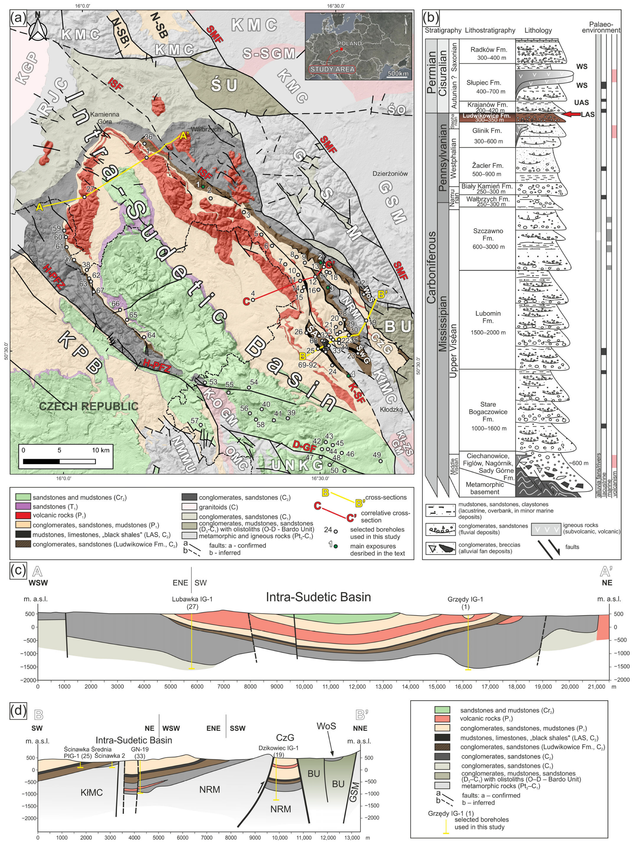
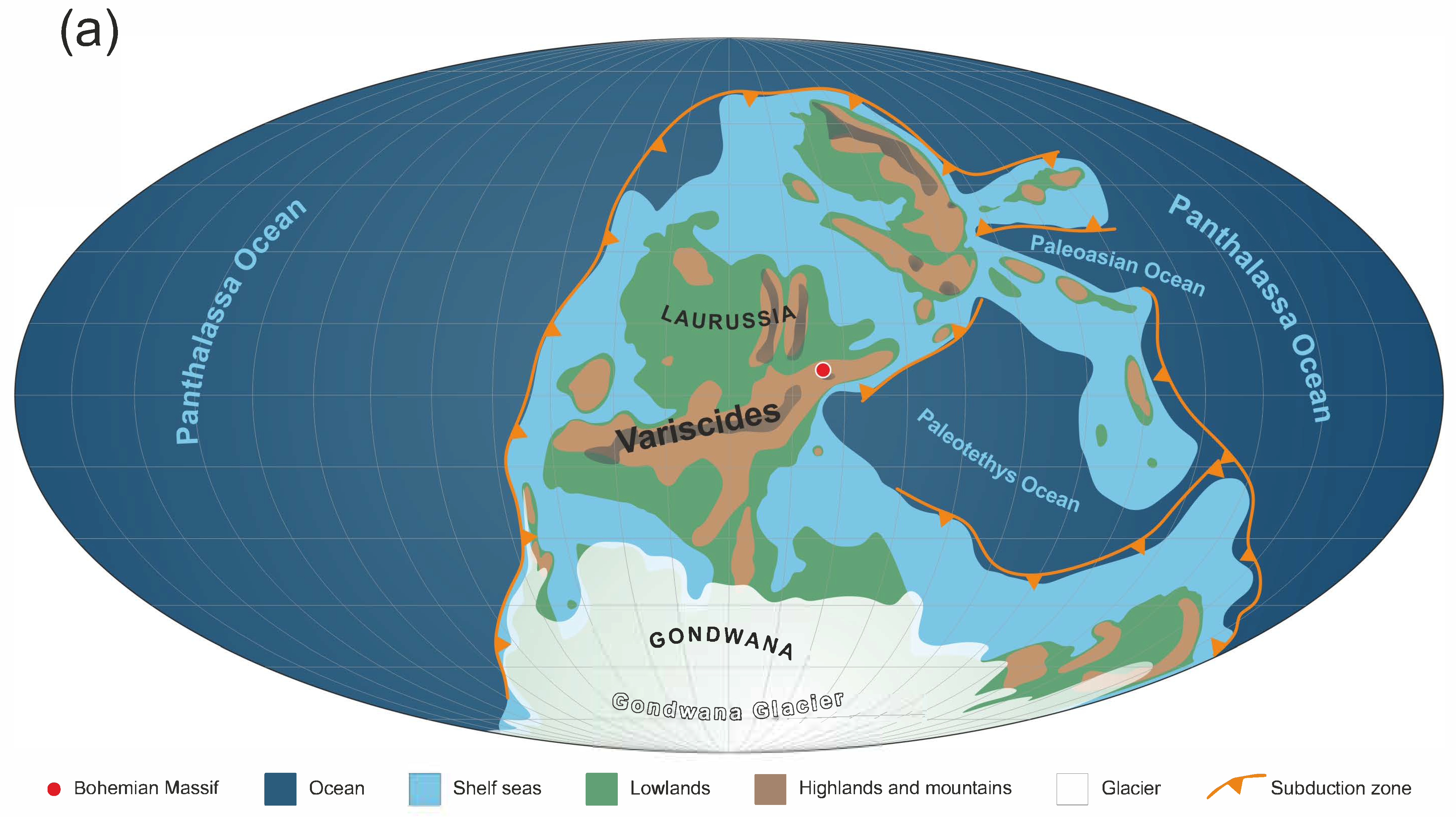
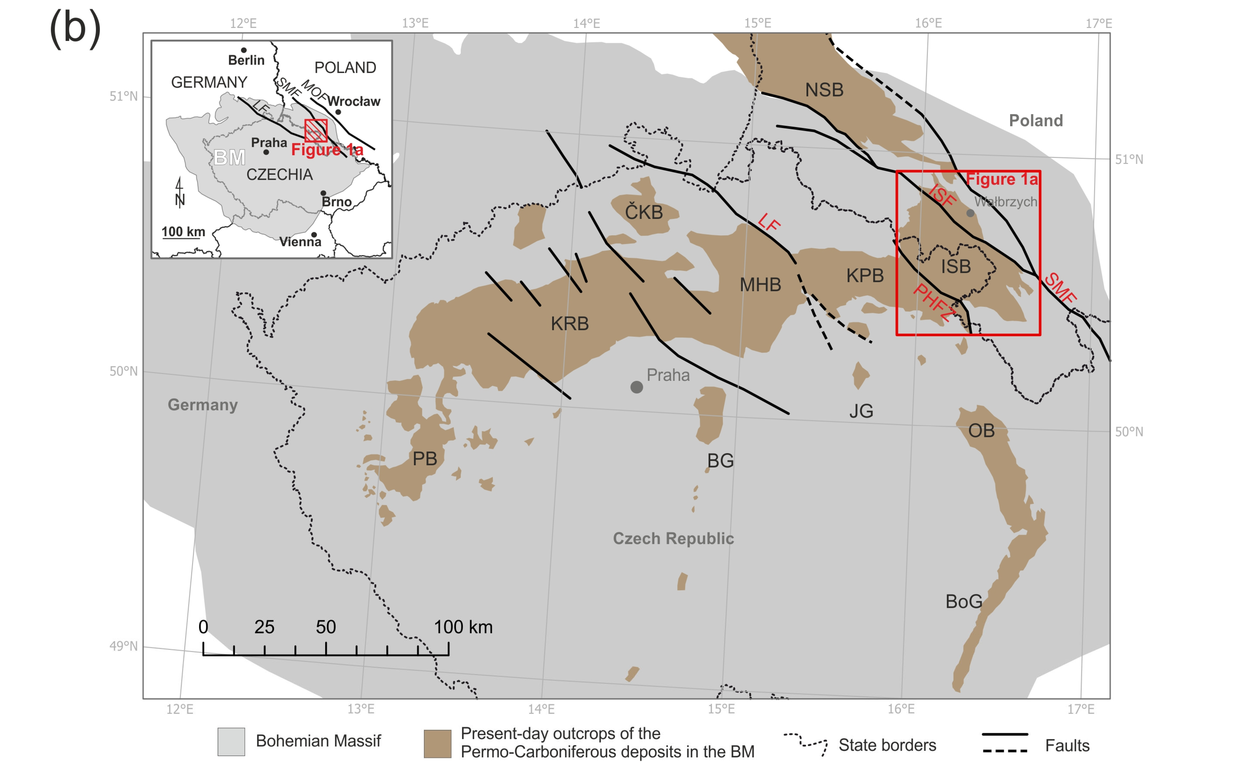
The Intra-Sudetic Basin (ISB) is a NW–SE-trending, multicyclic intramontane basin extending across southwestern Poland and northeastern Czech Republic, approximately 70 km in length and 35 km in width (Figure 1a). The basin formed in the northeastern Bohemian Massif—the easternmost part of the European Variscan orogenic belt—comprising lithospheric blocks that amalgamated through convergence between Laurussia and Gondwana during the Late Devonian to early Carboniferous (ca. 400–340 Ma), culminating in the assembly of the Pangea supercontinent (Figure 2a) [44,45,46,47]. Together with other extensional basins that developed in the Bohemian Massif during the Late Paleozoic, the ISB is classified as the easternmost part of the Pilsen–Trutnov Basin Complex (Figure 2b) [48,49,50]. Present-day basin boundaries are predominantly fault-controlled. The ISB adjoins crystalline massifs, including the Kaczawa Metamorphic Complex to the north, the Rudawy Janowickie Metamorphic Complex to the west, the Góry Sowie Massif to the east, and the Kłodzko Metamorphic Complex to the south (Figure 1). The northeastern margin of the basin is tectonically bounded by the Świebodzice Unit, which preserves a syn-orogenic Upper Devonian–Mississippian sedimentary succession [51]. To the southeast of the ISB, Devonian–Mississippian clastics and carbonates of the Bardo Unit are exposed, locally incorporating older olistoliths [52]. To the south, the ISB is separated from the Upper Nysa Kłodzka Graben [53,54], filled with Upper Cretaceous deposits, by the Duszniki–Gorzanów Fault. On the western side, the basin is bounded by the Poříčí–Hronov fault system, which forms the current tectonic boundary with the Krkonoše-Piedmont Basin [50].
The ISB began to form as a narrow intramontane trough at the end of the Variscan orogeny during the early to middle late Viséan (around 335–333 Ma) [55], and underwent a complex evolution from the Mississippian to the Late Cretaceous [35,56,57,58,59,60,61,62,63]. During the early Carboniferous, the northern and western parts of the basin were dominated by coarse-grained molasse-type clastics derived from the Rudawy Janowickie and Kaczawa complexes (Ciechanowice, Figlów, Nagórnik, Stare Bogaczowice and Lubomin formations; Figure 1b) [35,55,57,58,62]. During the late Viséan, a marine transgression inundated the northern part of the basin, resulting in the deposition of the Szczawno Formation in marginal deltaic and shallow marine environments [60,62,64,65]. Subsequent late Carboniferous sedimentation was dominated by fluvial processes, leading to the deposition of the coal-bearing Wałbrzych, Biały Kamień, and Žacléř formations (Figure 1b) [66,67,68,69,70] overlain by the Glinik Formation [35,71,72].
The Carboniferous succession culminates in the Ludwikowice Formation [35,72,73,74], which constitutes the primary focus of this study. This unit is distinguished as a fining-upward megacyclothem, composed of typical red-bed facies in its lower and middle parts [72]. The lowermost, fluvial part of this megacyclothem has traditionally been referred to as the Basal Conglomerate Member, which grades upward into the Platy Sandstone Member [75]. The upper part of the Ludwikowice Formation consists of fine-grained deposits assigned to the Lower Anthracosia Shale (LAS), composed predominantly of grey to black, fissile mudstones and limestones, locally enriched in organic matter [36,37,40,41,42,59] and containing characteristic bivalves of Anthracosia sp. In the Czech sector of the Intra-Sudetic Basin, the age- and stratigraphic equivalent of the Ludwikowice Formation is recognized as the Vernéřovice Member within the Chvaleč Formation [49,76]. Its counterpart to the LAS—the Vernéřovice Horizon—is composed of a laterally persistent grey limestone with chert nodules enclosed in bituminous mudstones bearing fish remains, locally passing into the ~0.5–0.8 m Rybníček Coal Horizon with associated grey mudstones and documented uranium mineralization [76].
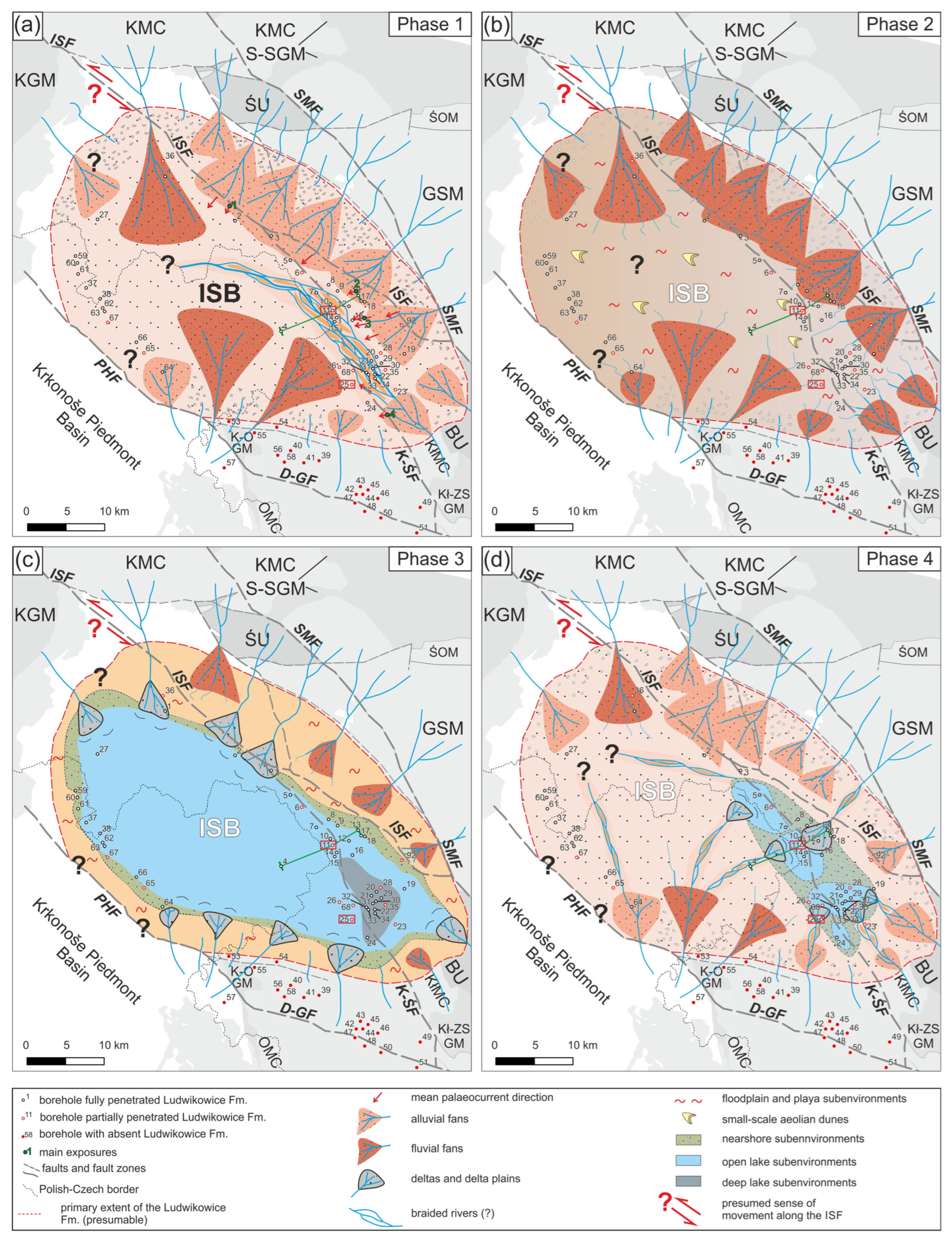
During the Early Permian, the ISB formed a semi-enclosed southern outlier of the broader Southern Permian Basin system in Central Europe [77,78]. The lower Permian infill of the ISB exhibits a pronounced cyclic megasequence architecture, comprising three major fining-upward successions—each reaching thicknesses of up to 700 m—represented by the Krajanów, Słupiec, and Radków formations (Figure 1b). Similarly to the Ludwikowice Formation, both the Krajanów and Słupiec formations form megasequences that culminate in fine-grained upper fluvio-lacustrine members, specifically referred to as the Upper Anthracosia Shale and the Walchia Shale, respectively [79,80,81,82]. These successions reflect a sedimentary evolution from proximal alluvial and fluvial fan systems to more distal environments, including playa, deltaic, and lacustrine settings [79,80,83,84]. The Krajanów Formation is the age- and stratigraphic equivalent of the Bečkov Member of the Chvaleč Formation in the Czech sector [49,76] and marks the base of the early Permian (Asselian) succession in the ISB. It has been interpreted as the record of a distributive fluvial system (DFS), based on its fan-shaped geometry, downstream grain-size reduction, and the lateral transition from amalgamated channel bodies to extensive floodplain and ephemeral lake deposits [79,85]. In this context, the underlying Ludwikowice Formation, marking the uppermost Carboniferous succession in the ISB, is explored here as a potential DFS analogue.
Figure 1. (a) Simplified geological map of the Intra-Sudetic Basin and neighboring tectonic units. The map is overlaid onto the digital elevation model (DEM) derived from the Shuttle Radar Topography Mission (SRTM) data [86]. Abbreviations: BU—Bardo Unit, CzG—Czerwieńczyce Graben, GSM—Góry Sowie Massif, KGP—Karkonosze Granite Pluton, KMC—Kaczawa Metamorphic Complex, KłMC—Kłodzko Metamorphic Complex, Kł-ZS GM—Kłodzko-Złoty Stok Granitoid Massif, KPB—Krkonoše Piedmont Basin, K-OGM—Kudowa-Olešnice Granitoid Massif; NMMU—Nové Město Metamorphic Unit, NRM—Nowa Ruda Ophiolite Massif, N-SB—North-Sudetic Basin (North-Sudetic Synclinorium), OMC—Orlica Metamorphic Complex, RJC—Rudawy Janowickie Metamorphic Complex, S-SGM—Strzegom-Sobótka Granitoid Massif, ŚA—Ścinawka Anticline, ŚwG—Święcko Graben, ŚO—Ślęża Ophiolite Massif, ŚU—Świebodzice Unit, UNKG—Upper Nysa Kłodzka Graben, WoS—Wolibórz Syncline. Main faults: D-GF—Duszniki-Gorzanów Fault, HPFZ—Hronov-Poříčí Fault Zone, ISF—Intra-Sudetic Fault, K-ŚF—Krajanów-Ścinawka Fault, SMF—Sudetic Marginal Fault. Geological map based on [87], modified and supplemented by the authors. (b) Synthetic stratigraphic scheme of the Carboniferous and Permian infill of the Intra-Sudetic Basin after [79,88], with minor modifications after [55,89]. Abbreviations: LAS—Lower Anthracosia Shale, UAS—Upper Anthracosia Shale, WS—Walchia Shale. The red arrow marks the uppermost interval of the Ludwikowice Formation penetrated by the boreholes studied. (c,d) Simplified cross-sections through the northern (A–A’) and southeastern (B–B’) parts of the Intra-Sudetic Basin, with selected boreholes used in this study indicated (based on [90]).
Minerals 15 01077 g001
The evolution of the late Carboniferous to early Permian basin fill was periodically disrupted by polymodal volcanic and subvolcanic activity [91,92,93], triggered by episodes of tectonic activity within the basin [93]. These processes, manifested through fault-controlled subsidence and coupled with climatic variability, are considered the primary controls on the development of the basin’s megacyclic fill architecture [59]. Within the stratigraphic record, several significant hiatuses are recorded across this interval, most notably during the Gzhelian and Sakmarian. These stratigraphic gaps coincide with major regional tectonic phases, including the Intra-Stephanian (Franconian) and Saale events [50]. In the Early Triassic, the ISB was filled with fluvial Buntsandstein deposits on a braided alluvial plain [94,95,96,97]. After a ~140 Ma hiatus, these strata were unconformably overlain by marine Upper Cretaceous deposits, locally up to 400 m thick [61,63,98].
The ISB, covering an area of approximately 1800 km2, is recognized in its present-day form as a tectonic synclinorium (the Intra-Sudetic Synclinorium), which developed through inversion of the primary basin structure, mainly during the Late Cretaceous–Paleogene compressional phase [99,100,101,102,103,104]. Its present-day structural configuration was further modified by subsequent Neogene (Alpine) deformation [103]. These tectonic events significantly deformed the basin fill and reactivated NW–SE and NE–SW-oriented fault systems. The synclinorial character is clearly expressed in the cross-sections shown in Figure 1. Some faults bounding these units were likely active during sedimentation and are also linked to Carboniferous–Permian magmatic activity. Notably, the southeastern sector of the synclinorium is dissected into a mosaic of grabens and horsts, which can also be interpreted as adjacent, fault-bounded synclines and anticlines [99] (Figure 1).
Figure 2. (a) Late Carboniferous (Pennsylvanian; late Gzhelian) paleogeographic reconstruction with the location of the Variscides and the Bohemian Massif in their eastern part, situated between Gondwana and Laurussia (after [105]). (b) Map showing Present-day outcrops (erosional remnants) of primary late Carboniferous–early Permian sedimentary basins in the Bohemian Massif (after [50,106,107,108]). Abbreviations: BG—Blanice Graben; BoG—Boskovice Graben; ČKB—Česká Kamenice Basin; ISB—Intra-Sudetic Basin; ISF—Intra-Sudetic Fault; JG—Jihlava Graben; KPB—Krkonoše Piedmont Basin; KRB—Kladno–Rakovník Basin; LF—Lusatian Fault; MHB—Mnichovo Hradiště Basin; MOF—Middle Odra Fault; NSB—North-Sudetic Basin; OB—Orlice Basin; PB—Pilsen Basin; HPFZ—Hronov-Poříčí Fault Zone; SMF—Sudetic Marginal Fault. The extent of Figure 1a is indicated by the red square.
Minerals 15 01077 g002aMinerals 15 01077 g002b

3. Dataset and Methods

3.1. Borehole and Surface Data

A total of 92 boreholes were analyzed in this study, including 83 from the Polish sector and 9 from the Czech sector of the ISB (Supplementary Table S1). The borehole data were obtained from the National Geological Repository (CBDG) of the Polish Geological Survey [109] and the repository of the Czech Geological Survey [110], as well as from published literature sources [73,111,112,113,114,115,116,117] (Figure 3a). The boreholes served as the basis for constructing isopach maps of the Ludwikowice Formation (Figure 3b), including a map illustrating the thickness of its uppermost part—the lacustrine deposits of the Lower Anthracosia Shale (Figure 3c). In addition, a percentage map was generated to illustrate the distribution of coarse-grained lithofacies throughout the entire formation along the downstream direction, based on paleotransport measurements obtained from exposures. Based on the presence and thickness of the Ludwikowice Formation, the boreholes were classified into three groups: 37 boreholes that fully penetrated the formation, 32 that intersected it partially, and 23 located in the southern and eastern parts of the basin where the formation is absent, but were included due to their relevance for paleogeographic interpretation. The analyzed boreholes were predominantly situated in the western, eastern, and southeastern sectors of the Intra-Sudetic Basin, with a notable lack of data from the central area, except for the Broumov (Brou-1) borehole (borehole 4; Figure 3a).
Lithological data were obtained from the boreholes that fully penetrated the Ludwikowice Formation (Figure 3a). Based on grain size, the deposits were grouped into three main categories: (1) conglomerates and coarse-grained sandstones; (2) fine-grained sandstones, siltstones, and mudstones; and (3) grey to dark-grey lacustrine sediments. Within the latter, coarse-grained grey sandstones were further distinguished and interpreted as representing nearshore and deltaic depositional environments. A more detailed lithological classification was not possible due to the ambiguous and inconsistent nature of archival borehole descriptions, which were prepared by various authors over different time periods during both exploration and research drilling campaigns. Notably, the research boreholes yielded the most detailed and reliable information on the studied formation. Comparable methodology has been applied in the Czech sector of the basin, where Late Paleozoic continental depositional environments and paleogeography were inferred from borehole-derived conglomerate–sandstone percentages to construct interval paleogeographic maps [106,107].

3.2. Core Descripton and Lithofacies Analysis

For this study, detailed sedimentological analyses were conducted on both borehole cores and surface exposures of the Ludwikowice Formation. Subsurface data were obtained from two boreholes—Ścinawka Średnia PIG-1 (SC; borehole 25) and Rybnica Leśna PIG-1 (RL; borehole 11)—where sedimentological logging and sampling were carried out. Additional wells intersecting the Ludwikowice Formation were assessed through compilation and interpretation of archival borehole descriptions and legacy logs. Complementarily, sedimentological analyses of the Ludwikowice Formation were carried out in a set of selected surface exposures, predominantly located in the northern and eastern parts of the ISB (Figure 1). Four exposures, considered representative of the lithological and facies variability of the lowermost Ludwikowice Formation, were selected for detailed analysis. The aim was to characterize the textural and structural features of the deposits and to identify the dominant depositional processes. The sedimentological study included macroscopic recognition, classification, and detailed lithofacies characterization, based on field observations and core descriptions. Vertical logging was employed to document variations in rock texture and sedimentary structures, while maximum particle sizes (MPS) within individual sedimentary units were recorded. Lithofacies were distinguished and coded in accordance with the widely applied scheme proposed by [118,119,120] with slight modifications, ensuring consistency between core and outcrop data. Particular attention was paid to the geometry, arrangement, and stacking patterns of sedimentary units, including their lateral and vertical transitions.
For the largest exposures, photomosaics and interpretive sketches were prepared using Hugin–Panorama Editor software (v. 2022.0.0.9) to document architectural elements and bounding surfaces at the exposure scale. Paleocurrent data were derived from cross-bedding and paleochannel axis measurements in exposures, plotted as rose diagrams with correction for tectonic tilt. Lithofacies identified in both boreholes and exposures were grouped into nine facies associations to reconstruct the fluvial-lacustrine depositional system of the late Carboniferous ISB and its internal variability. The integration of core and exposure data enables a comprehensive characterization of depositional environments and the stratigraphic architecture of the Ludwikowice Formation.

3.3. Petrography

Petrological analyses of 19 thin sections from the SC and RL boreholes were carried out on polished thin sections under reflected light using a Nikon Eclipse E600-POL polarizing microscope (Nikon Corporation (Nikon Instruments), Tokyo, Japan). Samples for analysis were selected to represent the lithological variability observed along the cores. In addition, thin sections of Ludwikowice sandstones exposed in the easternmost part of the basin were analyzed. High-resolution imaging was performed on carbon-coated thin sections and rock debris using a HITACHI S-4700 scanning electron microscope (SEM) (Hitachi High-Technologies Corporation, Tokyo, Japan) equipped with an energy-dispersive spectrometer ([EDS]; NORAN NSS, Middleton, WI, USA) in Scanning Electron Microscopy and Microanalysis Laboratory (Institute of Geological Sciences, Jagiellonian University, Kraków, Poland). Observations were conducted using a secondary electron (SE) signal to capture topography of the samples and a backscattered electron (BSE) signal to enhance compositional contrast.

3.4. Inorganic Geochemistry/Carbonate Content and Isotopic Composition

The elemental composition of 28 selected samples from the SC borehole and 20 from the RL borehole was determined with the use of inductively coupled plasma-optical emission spectrometry (ICP-OES) in the Laboratory of the Inorganic Geochemistry (Institute of Geological Sciences of the Jagiellonian University). To prepare, powdered samples were mineralized in a mixture of spectrally clean, concentrated nitric, hydrochloric, and hydrofluoric acids. Elemental analyses were carried out using an ICP-OES Spectro Arcos spectrometer (SPECTRO Analytical Instruments GmbH) with the radial (side-on) viewed torch configuration to measure the main elements and the axial (end-on) torch configuration to measure the trace elements. The OREAS 920 standard was analyzed in three replicates alongside the samples. Values obtained for the latter, between 95% and 105% of the certified values, were accepted. Elemental composition was utilized to construct the following geochemical proxies: C/P (paleoproductivity), Si/Al (terrestrial input), Fe/Mn (redox), (Na + Mg)/Al (aridity).
Calcium carbonate (CaCO3) content was determined using the Scheibler volumetric method with an Eijkelkamp calcimeter (Eijkelkamp Soil & Water, Giesbeek, Netherlands), with analytical errors consistently below 1%. Based on the measured carbonate content, a total of 33 bulk carbonate samples—18 from the SC borehole and 15 from the RL borehole—were selected for stable isotope analysis. Carbonates included: siderite (RL16-RL27), dolomite (SC14), and ankerite (SC12, SC16-2), which coexists with calcite in every sample but SC14 [43]. Given the fine-grained nature of the lacustrine deposits, no mineral separation was conducted before measurement.
Bulk isotope analysis was performed by GeoZentrum Nordbayern. Carbonate powders were reacted with 100% phosphoric acid at 70 °C using a GasBench II system coupled to a ThermoFisher Delta V Plus isotope ratio mass spectrometer (Thermo Fisher Scientific, Bremen, Germany). All isotopic data are reported in per mil (‰) relative to the Vienna Pee Dee Belemnite (V-PDB) standard. Analytical reproducibility and accuracy were assessed through replicate measurements of internal laboratory standards, calibrated to δ13C values of +1.95‰ for NBS19 and −47.3‰ for IAEA-CO9, and δ18O values of −2.20‰ for NBS19 and −23.2‰ for NBS18. Reproducibility was within ±0.7‰ for δ13C and ±0.4‰ for δ18O. Standard NBS19 was additionally analyzed as a quality control throughout the analytical sequence. Oxygen isotope values obtained from dolomite, siderite, aragonite, and other carbonate phases were corrected using phosphoric acid fractionation factors as proposed by [121,122].

3.5. Magnetic Susceptibility

The magnetic susceptibility (MS) signal in sedimentary rocks represents the total amount of magnetic minerals (pyrite, siderite, ankerite, ferrous oxides) present in the analyzed sample. Magnetic susceptibility (MS) was measured with a ZH Instruments SM-30 magnetometer, and the measurements are bulk and unoriented. MS determinations were taken on cut specimens, in an open area, away from any sources that might interfere with the measurement, and it was performed on the flattest possible surface. For each sample, three measurements were recorded and averaged to obtain final values.

3.6. Organic Petrology

Fine-grained, organic-rich lacustrine deposits of the LAS, typically dark grey to black in color, formed the primary subject of microscopic analysis. Organic petrology investigations were conducted on 27 samples retrieved from the cores of the RL and SC boreholes. Whole-rock samples were embedded in epoxy and polished perpendicular to bedding planes, following standard preparation procedures in accordance with ISO 7404-2 [123], and subsequently examined petrographically. Petrographic observations were carried out using a Zeiss AxioImager 1 Am (Carl Zeiss Microscopy GmbH, Oberkohen, Germany) reflected-light microscope equipped with both white light and UV illumination systems. An HBO fluorescence lamp was used for the detection of maceral fluorescence under UV excitation, while standard white light facilitated conventional petrographic observations, as recommended by [124,125]. Organic components were analyzed under oil immersion at 200× to 500× magnification in both reflected white light and fluorescence modes.
Maceral composition was determined through point-counting using a Zeiss KS RUN 300 system (Carl Zeiss Microscopy GmbH, Oberkohen, Germany). For each sample, up to 300 points were analyzed, excluding mineral matter. The relative abundances of vitrinite, liptinite, inertinite, solid bitumen, and bituminous groundmass were recorded. Macerals were identified based on their morphology, reflectance, and fluorescence properties, following the nomenclature and guidelines of the International Committee for Coal and Organic Petrology [124,126,127,128]. The resulting maceral data were used to infer the composition and types of organic matter, and to classify organic associations in the sense of [39].
Vitrinite reflectance measurements (random, oil immersion) were performed using the same microscope setup equipped with a 50× objective and an MSP 200 photometric system (J&M GmbH, Villingendorf, Germany). Measurements were taken under monochromatic light at 546 nm and calibrated using sapphire (0.591% Ro) and yttrium–gallium–garnet (0.905% Ro) standards. All reflectance measurements adhered to the protocols of the ICCP [123,124,129,130].

3.7. Palynology

Rock samples for palynological and palynofacies analysis were processed using a standard maceration protocol. Initially, samples were cleaned and crushed, followed by sequential acid treatment with hydrochloric acid (HCl) to remove carbonates and hydrofluoric acid (HF) to dissolve silicate minerals. After maceration, each sample was divided into two subsamples for separate analytical purposes. The first subsample, intended for palynofacies analysis, was left unoxidized and subjected only to thorough rinsing and centrifugation. The second subsample, designated for miospore analysis, underwent oxidation using 65% nitric acid (HNO3) and potassium chlorate (KClO3). This portion was subsequently cleaned by repeated washing and centrifugation, then sieved using fine-mesh microsieves.
Microscope slides were prepared from both the unoxidized and oxidized residues. Palynofacies analysis was performed on slides from the unoxidized material, while miospore analysis was conducted on slides from the oxidized fraction. All preparations were examined under a Nikon Optiphot transmitted light microscope (Nikon Corporation, Tokyo, Japan). For palynofacies analysis, particle identification and classification followed the scheme of [131], as modified by [132], with a total of 250–300 particles counted per sample. During the miospore study, at least 100 specimens were analyzed with respect to taxonomy, morphological preservation, and thermal maturity. The latter was based on the coloration of Lycospora specimens and evaluated using the seven-level spore color index (SCI) scale proposed by [133,134].

4. Results

4.1. Extent and Thickness of the Ludwikowice Formation

The thickness of the Ludwikowice Formation exhibits significant lateral variation across the study area, reflecting its stratigraphic position within both proximal and distal depositional zones of the late Carboniferous ISB (Figure 3b). Typically, the Ludwikowice Formation conformably overlies grey, fluvial deposits of the Glinik Formation (referred to as the Odolov Formation in the Czech sector of the basin) [50,71,72,135]. However, in the southernmost part of the basin (e.g., borehole 24), it directly overlies the metamorphic basement of the Kłodzko Metamorphic Complex [83]. In general, a progressive thickening trend is observed from the eastern, northeastern, and southeastern parts of the basin toward its central and western sectors. This thickening, ranging from approximately 150 m to 450–500 m, is particularly pronounced west and southwest of the Intra-Sudetic Fault, with the maximum values recorded along a NW–SE-oriented depocenter near the Krajanów–Ścinawka Fault. In the vicinity of Nowa Ruda, the Ludwikowice Formation exceeds 600 m in thickness (borehole 34). In contrast, to the south, the formation is entirely absent in several boreholes (Figure 3b), where younger Permian strata are either restricted to the Słupiec Formation or entirely missing. In these areas—particularly north of the Pstrążna–Gorzanów Fault—Upper Cretaceous marine deposits rest directly on the metamorphic basement, indicating long-term stratigraphic discontinuity. A gradual thinning of the Ludwikowice Formation is also evident toward the basin’s western margin, particularly in the vicinity of the Hronov–Poříčí Fault, where its thickness decreases to approximately 50 m near Okrzeszyn. Between the Lubawka IG-1 borehole (borehole 27) and boreholes located on the Czech side of the basin, the formation maintains a relatively consistent thickness of around 50–100 m. Although no borehole data are available from the central, currently deepest part of the basin, paleogeographic reconstructions suggest that no significant subsidence centers existed there during the latest Carboniferous and early Permian either [67]. This region likely functioned as a source area during the early Carboniferous, suggesting that the basin configuration was inherited from this earlier period. Consequently, the accumulation of uppermost Carboniferous to lowermost Permian deposits in this area was likely limited.
Similar thickness variations are observed in the uppermost part of the Ludwikowice Formation, particularly within the lacustrine and deltaic deposits assigned to the LAS, corresponding to the Verneřovice Horizon in the Czech sector (Figure 3c). Increased thicknesses of this member—reaching up to approximately 135 m (borehole 30)—are recorded near Nowa Ruda, especially between the Intra-Sudetic- and the Krajanów–Ścinawka faults. A gradual thinning trend is observed toward the west and northeast, consistent with the location of presumed sediment source areas and a reduction in accommodation space during the late Carboniferous. As with the total thickness distribution of the Ludwikowice Formation, the LAS exhibits a progressive westward thinning, at relatively constant values of approximately 5–10 m across the distal western sectors of the basin.
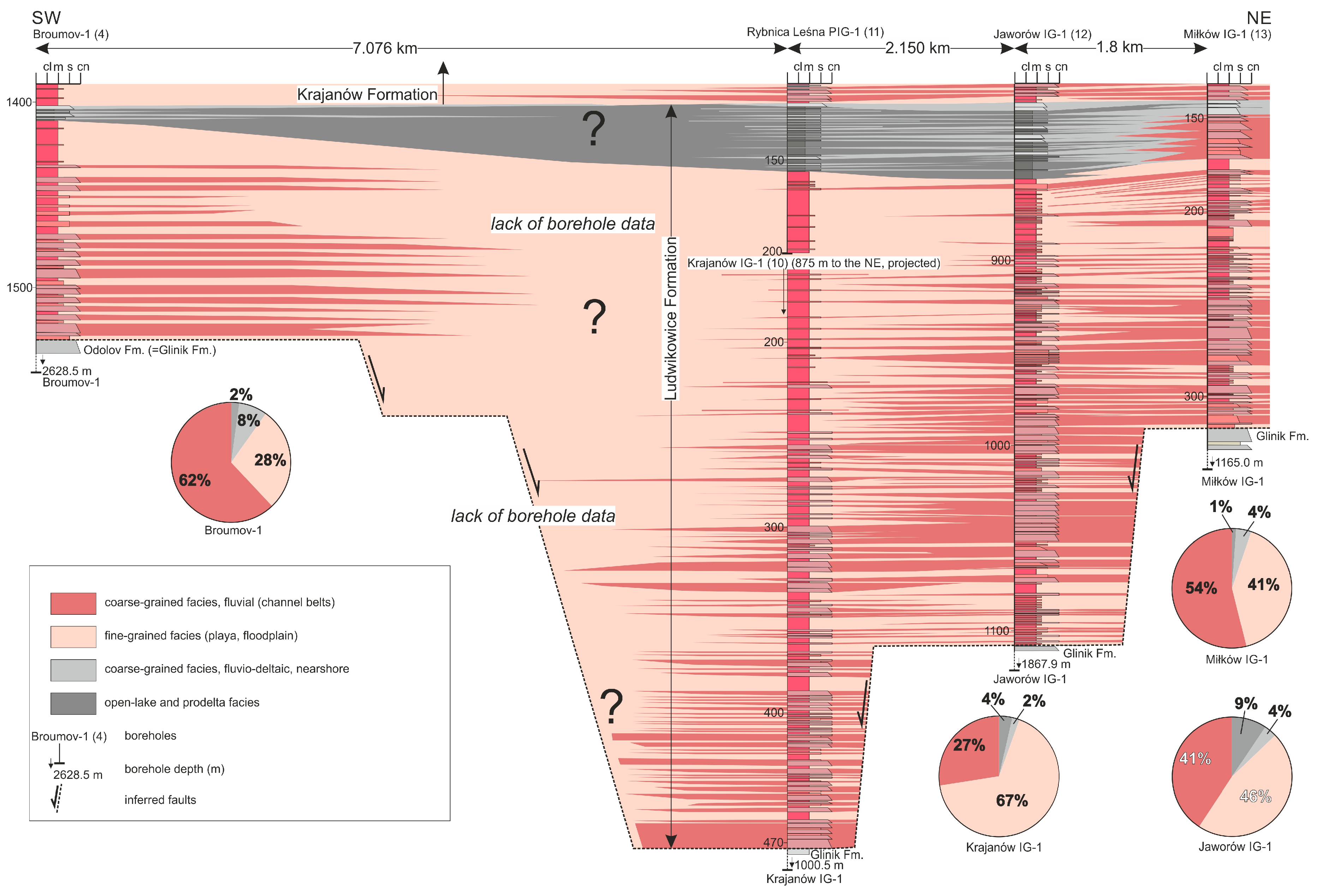
Across the entire Ludwikowice Formation within the ISB, a gradual decrease in the percentage of coarse-grained sediments is observed towards the central part of the basin. This trend is particularly well illustrated in the correlation and pie charts presented in Figure 4. Notably, distinct areas of increased coarse-grained deposits are evident in the northeastern part of the basin, where their content locally reaches up to ~90%, and in the southern part of the basin, north of the Duszniki–Gorzanów Fault, where values of up to ~70% are recorded (with borehole 4 yielding 63%). Furthermore, an additional zone interpreted as reflecting an elevated proportion of coarse-grained facies is suggested to the west of borehole 4.
A similar pattern, accompanied by a gradual decrease in the percentage of coarse-grained deposits, can be observed in the distribution of grey-colored lacustrine sediments, which are represented by open-lake and prodelta organic-rich lithofacies. These facies are commonly associated with coarse-grained fluvio-deltaic and nearshore facies, occurring in the majority of the analyzed boreholes in the uppermost part of the formation. In the studied cross-section (Figure 4), the proportion of coarse-grained fluvial deposits decreases from approximately 59% in the Miłków IG-1 borehole (borehole 13), to 41% in Jaworów IG-1 (borehole 12), and to about 27% in Krajanów IG-1 (borehole 10; Figure 4). Correspondingly, the content of fine-grained deposits increases from 41%, through 46%, to 67% in these boreholes. In contrast, the Broumov-1 borehole (borehole 4) reveals a markedly higher proportion of coarse-grained lithologies—approximately 62%. The proportion of lacustrine facies (grey, organic-rich lithofacies) systematically increases southwestward and westward: from 1% in Miłków IG-1, through 9% in Jaworów IG-1, to 14% in Krajanów IG-1 (Figure 4).

4.2. Lithofacies and Facies Associations

Thirty-eigth lithofacies were distinguished within the Ludwikowice Formation (Table 1). They were identified primarily from core data in the SC and RL boreholes, and secondarily from outcrops in the eastern part of the ISB (Figure 3a). These lithofacies are shown on the sedimentary logs and described in detail in Table 1. Based on genetic characteristics and spatial relationships, they were grouped into nine facies associations that together represent components of a late Carboniferous fluvio-lacustrine depositional system in the Intra-Sudetic Basin.

4.2.1. Fluvial Facies Association (FA1)

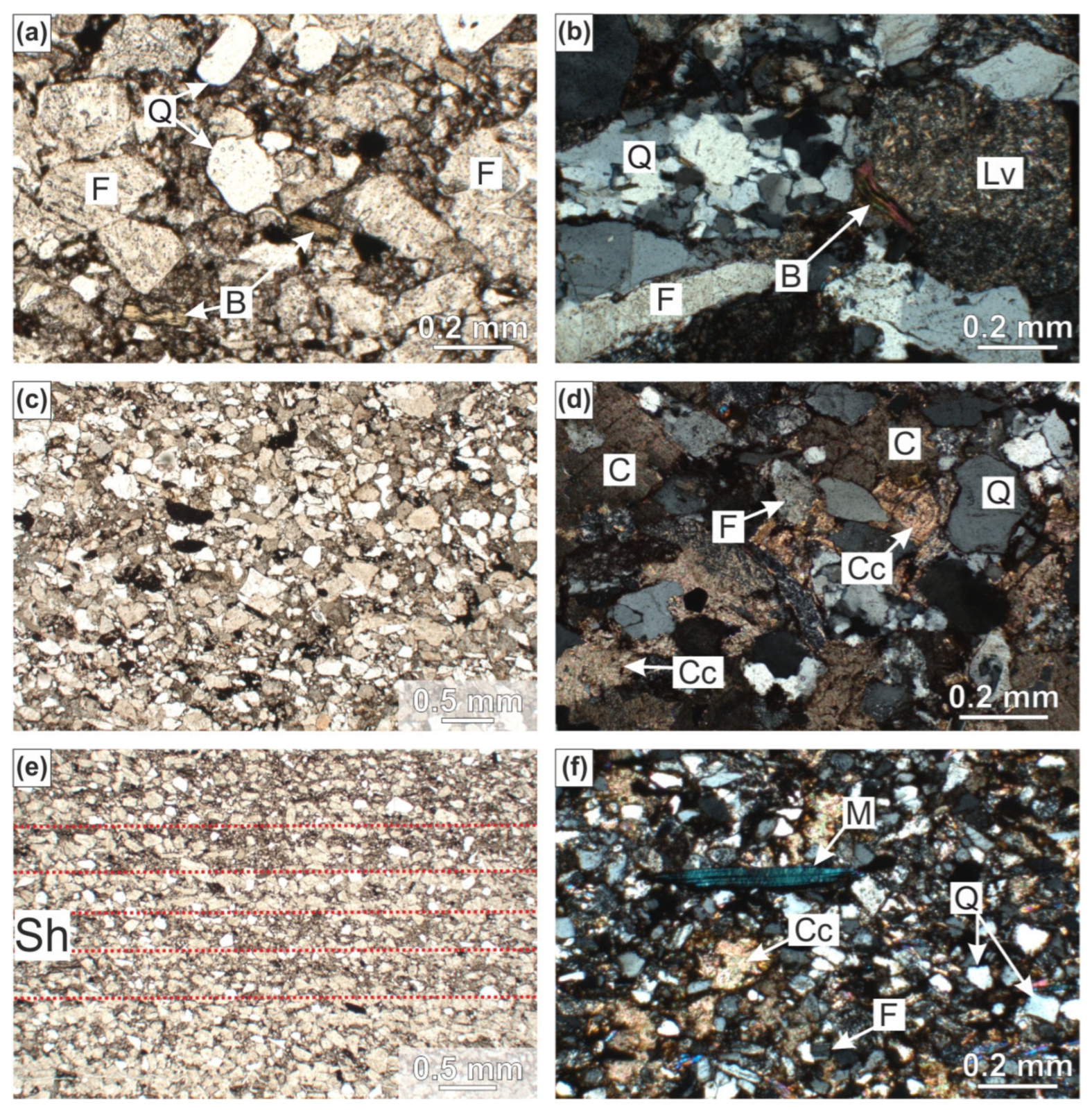
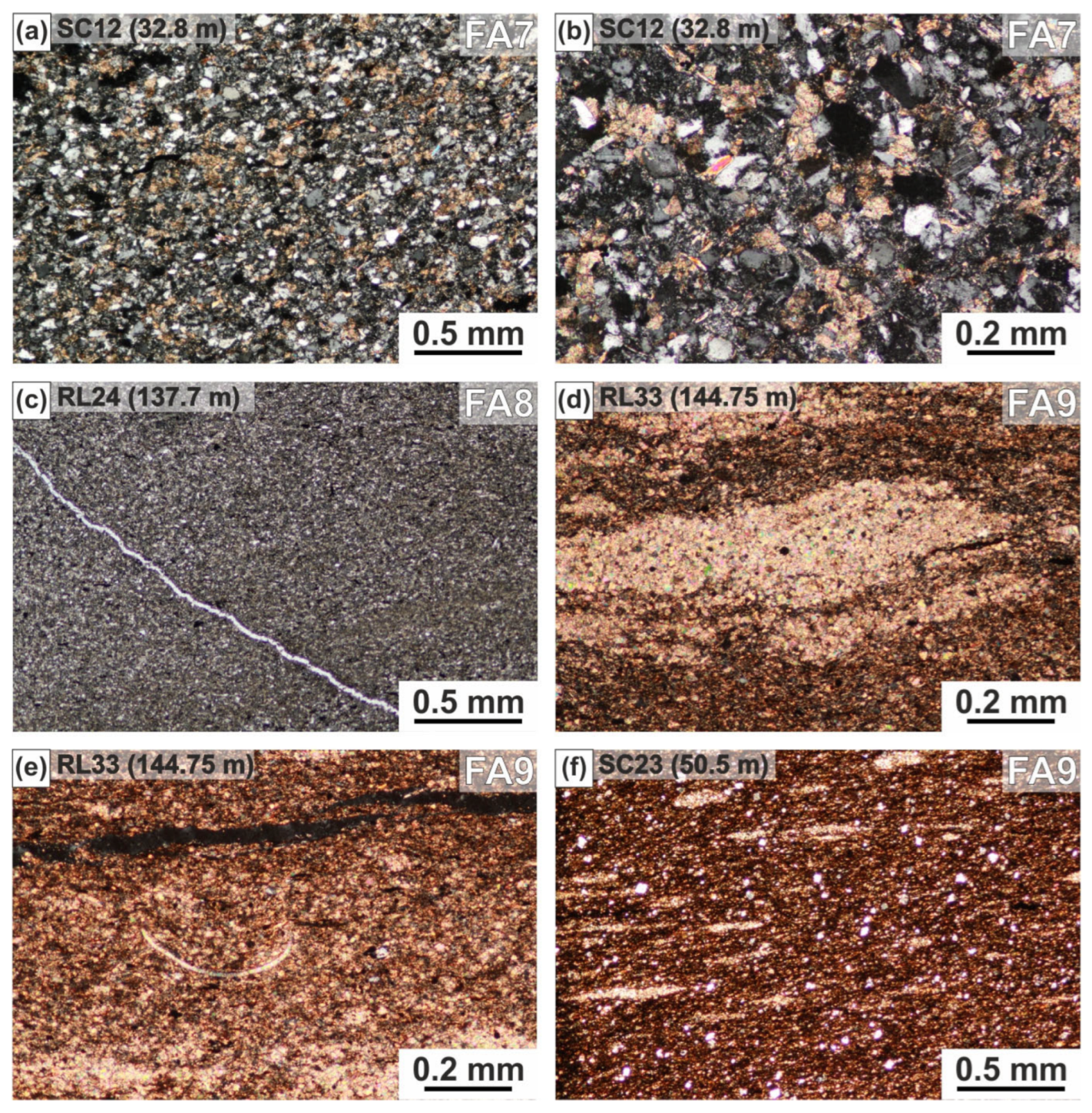
Facies Association FA1 consists predominantly of gravelly and sandy lithofacies. These deposits were identified in exposures located in the eastern and northern parts of the ISB, as well as in the lowermost interval of the SC borehole (200–183 m), where they co-occur with FA2 deposits. They comprise well-cemented, brownish to dark reddish arkosic to subarkosic and lithic arenites that are poorly to moderately sorted. Up-section, the proportion of carbonate cement increases (Figure 5).
The lower parts of composite beds consist of gravel-dominated facies including Gcm (massive, clast-supported conglomerates) and Gcg (normally graded conglomerates), and subordinately of Gh and GSh, which commonly grade upward into cross-bedded units of Gp, GSp, Sp, SGp as well as Gt, GSt, St, SGt (Figure 6). The upper parts of beds typically consist also of Sh and Src sandstones, and are locally capped by Mmb (massive mudstones), notably in the lower interval of the SC borehole. Additional facies include matrix-supported conglomerates (Gmm, Gmg) and massive or deformed sandstones (Sm, Sg, Sd).
Gcm and Gcg lithofacies indicate high-energy tractional transport and deposition of coarse lag deposits at the bases of fluvial channels [118,120,136]. Gh and GSh lithofacies are interpreted as products of diffuse gravel sheets and longitudinal bedforms formed under traction currents within river channels [137,138]. Gp, GSp, Sp, and SGp represent straight-crested, 2D gravelly and sandy dunes, while Gt, GSt, St, and SGt reflect sinuous-crested, 3D bedforms—both sets forming gravelly and sandy mid-channel bar complexes [118]. The Sh facies records plane-bed transport over gravelly and sandy bars and washed-out dunes (Sl lithofacies) during peak flows, with transitions into Src, which indicates waning-stage ripple migration under low-velocity currents. These are occasionally draped by Mm and Mmb, deposited from suspension during periods of channel abandonment or bar-top submergence, followed by subaerial exposure. Matrix-supported conglomerates of the Gmm and Gmg lithofacies are linked to high- and low-strength debris flows entering river channels or floodplains during high-discharge flood events [118]. Sm and Sg represent deposition from sandy, high-density flows or sediment-laden currents, while Sd most likely records post-depositional deformation caused by liquefaction or rapid loading [139].
This lithofacies association records amalgamated fluvial channel infills formed within a gravelly braided river system [118]. The deposits reflect rapid lateral and vertical accretion of mid-channel and bar-top bedforms, interrupted by episodic sediment gravity flows. Erosional, concave-upward basal contacts and sheet-like geometries suggest repeated channel avulsion. Locally developed mass flow deposits resulted probably from short-lived, high-density flood events. Paleotransport indicators from the eastern and northeastern parts of the ISB consistently point to westward and southwestward flow (Figure 3d), reflecting sediment delivery from the uplifted basin margins into a structurally confined, fluvial system.

4.2.2. Sandy to Muddy Floodplain Facies Association (FA2)

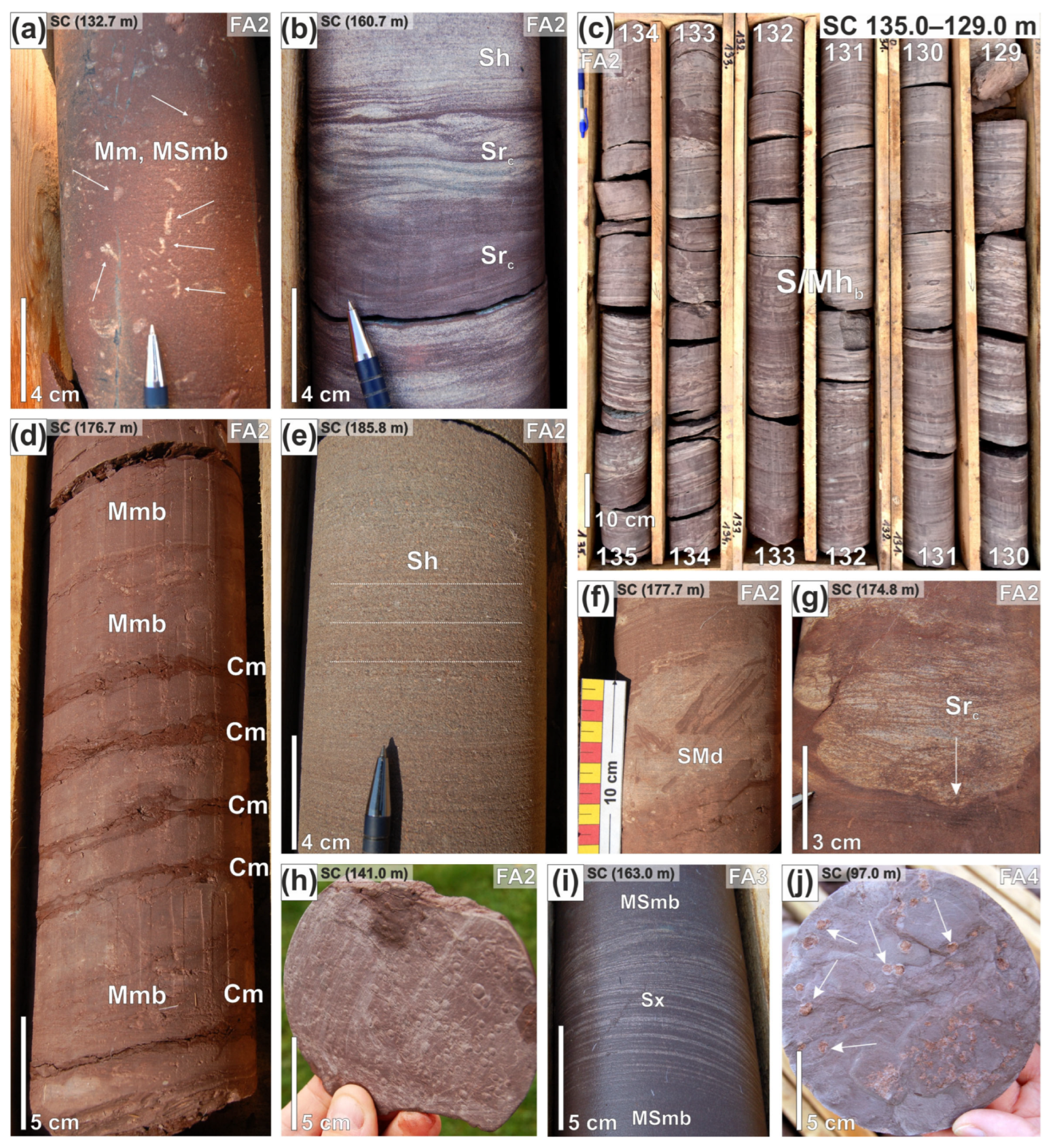
Facies Association FA2 is dominated by brown mudstones and very fine- to fine-grained sandstones, particularly of Mm, Mmb, and MSmb lithofacies, which are massive to bioturbated and frequently display mottling, root traces/rhizoliths, carbonate nodules, and/or nearly continuous carbonate horizons, and other pedogenic features (Figure 7 and Figure 8a). These deposits were identified in thick intervals of the SC borehole (183–98.6 m) and the RL borehole (200–168 m). The fine-grained deposits are interbedded with ripple-laminated sandstones (mainly Src, occasionally Srcl; Figure 8b) and sandstone–mudstone couplets with flaser to lenticular cross-bedding (Srle). Where these facies alternate with mudstones, they form heterolithic units classified as S/Mhb (Figure 8c). The Mmb facies contains up to 1 cm thick laminae of claystone (Figure 8d). Within the Mm, Mmb, and MSmb facies, there are also thin intercalations of massive- and horizontally-laminated sandstones (Sm and Sh, respectively; Figure 8e). Deformed heterolithic facies are also present and include muddy or sandy units containing mudstone clasts within sandy matrix or vice versa, and commonly exhibit load structures, clastic dykes, desiccation cracks, and small-scale slump folds (Figure 8f,g). In addition, raindrop imprints are locally preserved (Figure 8h).
Facies Association 2 (FA2) is interpreted as representing a sandy- to muddy-dominated floodplain subenvironment [118]. The dominance of Mmb and MSmb facies indicates deposition from muddy suspended load, followed by periods of subaerial exposure, drying, and soil development as well as prolonged suspension settling in ephemeral ponds. Ripple-laminated sandstones, together with heterolithic beds, reflect brief flow incursions, followed by episodes of drying and pedogenesis. The occurrence of deformed horizons suggests high-energy, sediment-laden surges and rapid dewatering of sediments, with some of these structures possibly representing seismites (e.g., [140,141,142]). The overall character of this association is consistent with low-gradient floodplain mudflats, where suspended mud deposition prevailed, although minor tractional transport of fine-grained sediments also occurred.

4.2.3. Aeolian Facies Association (FA3)

This facies association is restricted to centimeter-scale horizons of parallel-laminated sandstones (Sx) composed of fine- to coarse-grained, pale yellow to reddish, very well-sorted sand. Within the 169–149 m interval of the SC borehole, these deposits display pinstripe lamination—closely spaced, sub-millimeter planar laminae that are horizontal to gently inclined, observable at the centimeter- to decimeter-scale in core (Figure 8i), and locally diffuse or rhythmic.
These features are interpreted as aeolian wind-ripple strata or sand sheets, deposited on interdune flats or dune flanks under low-energy, unidirectional wind conditions [143]. The associated dunes were likely small-scale, consistent with the limited extent and thickness of the aeolian facies association, as no thicker aeolian deposits have been identified within the Ludwikowice Formation. The described forms are thought to have migrated onto the sandy- to muddy floodplain subenvironment discussed previously, forming part of a fluvio-lacustrine system [144] of the ISB.

4.2.4. Playa Lake Margin/Coastal Mudflat Facies Association (FA4)

Facies Association FA4 shares many characteristics with FA2, especially in its lower interval, and is likewise dominated by brown mudstones and very fine- to fine-grained sandstones, particularly of the Mm, Mmb, and MSmb lithofacies. These deposits occur between 98.6 and 65 m in the SC borehole and 168–157 m in the RL borehole. They are typically massive to bioturbated, displaying mottling, root traces/rhizoliths, carbonate nodules, and in some intervals, nearly continuous carbonate horizons—all indicative of prolonged subaerial exposure and soil development. A diagnostic feature of FA4 is the presence of carbonate pseudomorphs after sulfates (Figure 8j), along with fine sulfate veins that cut the core vertically or at low angles, and horizontal sulfate-rich veins typically 1–2 mm thick. These structures suggest a late-stage diagenetic overprint, developed under intermittently evaporative conditions. Another distinguishing lithofacies is the occurrence of grey, non-calcareous mudstones (Mmg), which are typically structureless or weakly laminated, and commonly form discrete beds or intercalations within brown mudstone intervals with gradational boundaries.
Facies Association FA4 is interpreted as representing lacustrine margin environments (playa lake margin/coastal mudflat), particularly ephemeral lake fringes or ponded floodplain depressions. The dominance of pedogenically modified mudstones (Mmb, MSmb) reflects subaerial exposure, drying, and soil development on abandoned or intermittently flooded lake margins. The presence of sulfate veins and evaporite pseudomorphs points to evaporitic conditions during late-stage drying episodes, while grey mudstones (Mmg) record subaqueous suspension fallout during brief lacustrine incursions or ponding events, potentially following localized flooding or rainfall. The frequent interbedding of S/Mhg and Src facies observed in the RL borehole further suggests rapid alternation between emergent and submerged conditions. Altogether, FA4 reflects sedimentation in transitional zones between the sandy to muddy floodplain and shallow lacustrine system, typical of semi-arid to seasonally humid climates with fluctuating water tables.

4.2.5. Nearshore Facies Association (FA5)

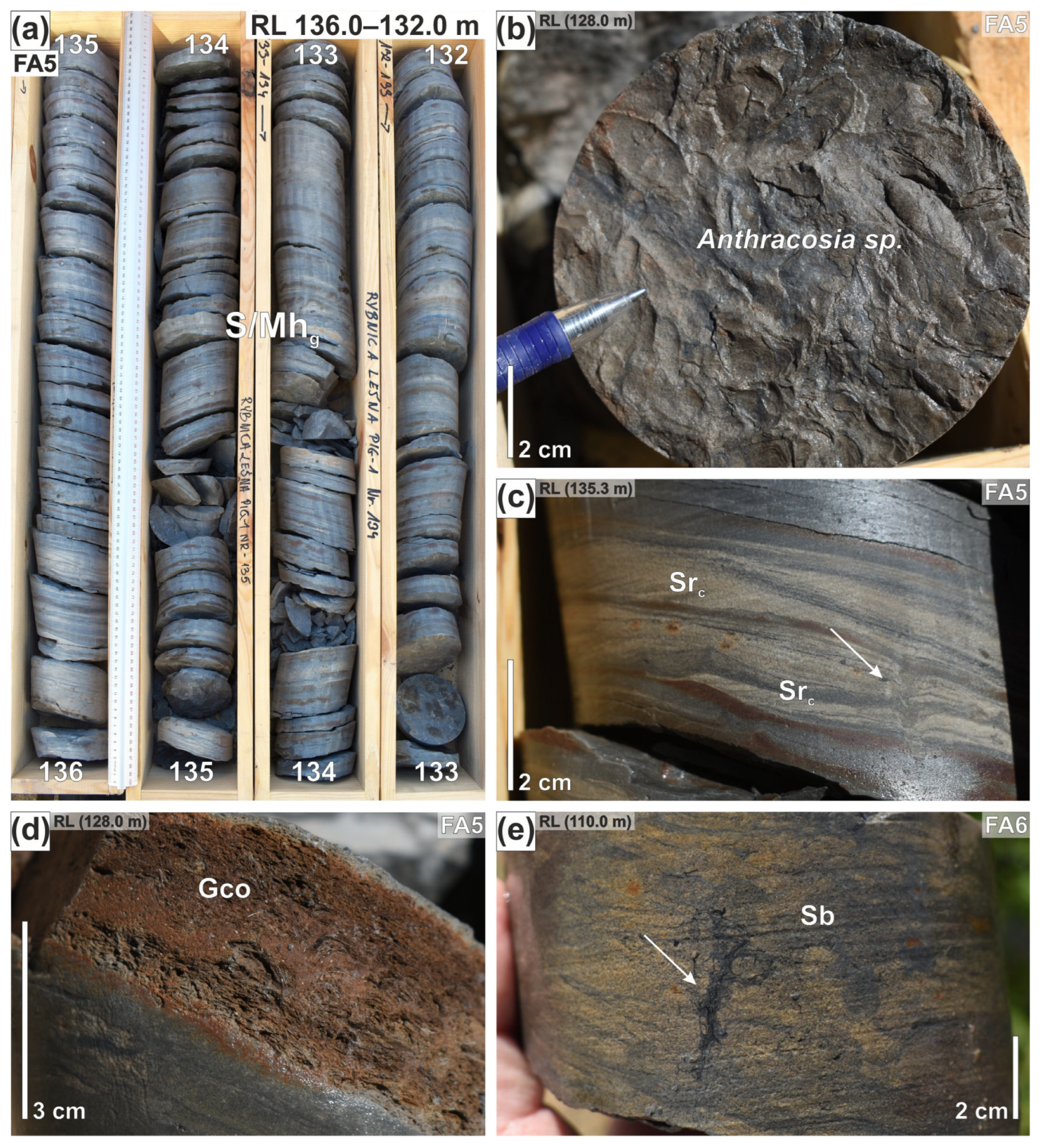
Facies Association FA5 is characterized by a dominance of greenish-grey heterolithic deposits (S/Mhg; Figure 9a), accompanied by calcareous mudstones (Mm (c)), ripple-laminated sandstones (Src), and localized coquina beds (Gco; Figure 9b). A poorly defined occurrence of the FA5 depostis is noted between 65 and 63 m in the SC borehole, where it co-occurs with deposits of FA7 (subaqueous delta front and subaqueous fan facies association) in the intervals 31.5–28.4 m and 27.2–24.9 m. These deposits are also common in the RL borehole, where they occur between 157 and 152.7 m, and also above the open-lake (FA9) and prodelta (FA8) deposits, within the interval 137.8–121.3 m. The most prominent facies is the heterolithic S/Mhg—composed of well-sorted, micaceous, fine- to medium grained sandstone and green to grey mudstone, both often arranged in thin, ripple-laminated sand–mud couplets (Figure 9a). These deposits commonly contain interbedded Src lithofacies and siderite-rich lenses or nearly continuous horizons. Bioturbation is prevalent and includes burrowing structures and escape traces (Figure 9c), with occasional in situ preservation of Anthracosia bivalves or their impressions, particularly well-developed in the RL borehole. Intercalated within this facies association are Mm (c) mudstones—grey, calcareous, massive to weakly laminated units—which locally show weak bioturbation, or burrow mottling. Additionally, laterally extensive shell lags or clusters of Anthracosia sp. fragments (Gco lithofacies; Figure 9d), occur within sharp-based, convex-up accumulations, representing high-energy reworking and winnowing of sand-size particles.
Overall, FA5 is interpreted as representing lacustrine nearshore environments, developed along shallow lake margins [145]. The alternation of calcareous mudstones, ripple-laminated heterolithics, and storm-generated shell beds reflects depositional variability controlled by seasonal changes in lake level, storm activity, and local sediment input. The presence of coquina beds (Gco) suggests occasional erosive events, likely related to storms or sudden water-level changes, during which finer particles were removed and shell debris concentrated [145].

4.2.6. Delta Plain Facies Association (FA6)

Facies Association FA6 occurs exclusively in the uppermost Ludwikowice Formation and continues into the lowermost part of the overlying Krajanów Formation, recording the transitional zone between these two fining-upward megacyclothems. In the SC borehole, within the 21.6–10.0 m interval, FA6 is composed almost entirely of massive dark grey mudstones (Mm (g) lithofacies), interbedded with thin beds of structureless or trough cross-bedded sandstones (St). These mudstones are locally bioturbated and exhibit subtle pedogenic features (Figure 9e). Occasionally, intercalations of massive sandstones (Sm) occur, some of which retain trough cross-bedding (St) in their lower parts. In the RL borehole, above 121.3 m, FA6 is successively replaced by fluvial deposits of FA1 belonging to the Krajanów Formation. Here, FA6 comprises grey and red to reddish-brown mottled mudstones (Mm), associated with fluvial channel-fill deposits of the Gcg, Gh, and GSt lithofacies, which grade upward into Gt, SGt, and Sm, locally capped by ripple-laminated sandstones (Src). Plant fragments are common, and siderite concretions frequently occur within the non-calcareous mudstones of the Mm lithofacies.
This facies association is interpreted as representing the upper delta plain, deposited under transitional fluvio-deltaic to lacustrine conditions [145]. The abundance of pedogenically modified mudstones and fine-grained sandstones, localized fluvial channel fills, and ripple-laminated sandstone indicates a heterogeneous, low-energy depositional environment, including intermittently flooded delta-top plain, ephemeral shallow ponds, and narrow distributary channels. The combination of mottling, rhizoliths, and reddish coloration in the mudstones reflects episodes of subaerial exposure and soil formation. The presence of siderite concretions within non-calcareous mudstones supports deposition under reducing conditions in poorly drained, organic-rich zones of the delta top. Occasional massive sandstones (Sm) interbedded with St cross-bedded intervals reflect brief high-energy incursions—likely channel avulsions or crevasse splays—followed by rapid sand deposition. Collectively, these features record the progradation of a distributive fluvial system (DFS) over former lake-margin environments, documenting a key stratigraphic and environmental transition at the boundary between the late Carboniferous Ludwikowice- and the early Permian Krajanów formations.

4.2.7. Subaqueous Delta Front and Subaqueous Fan Facies Association (FA7)

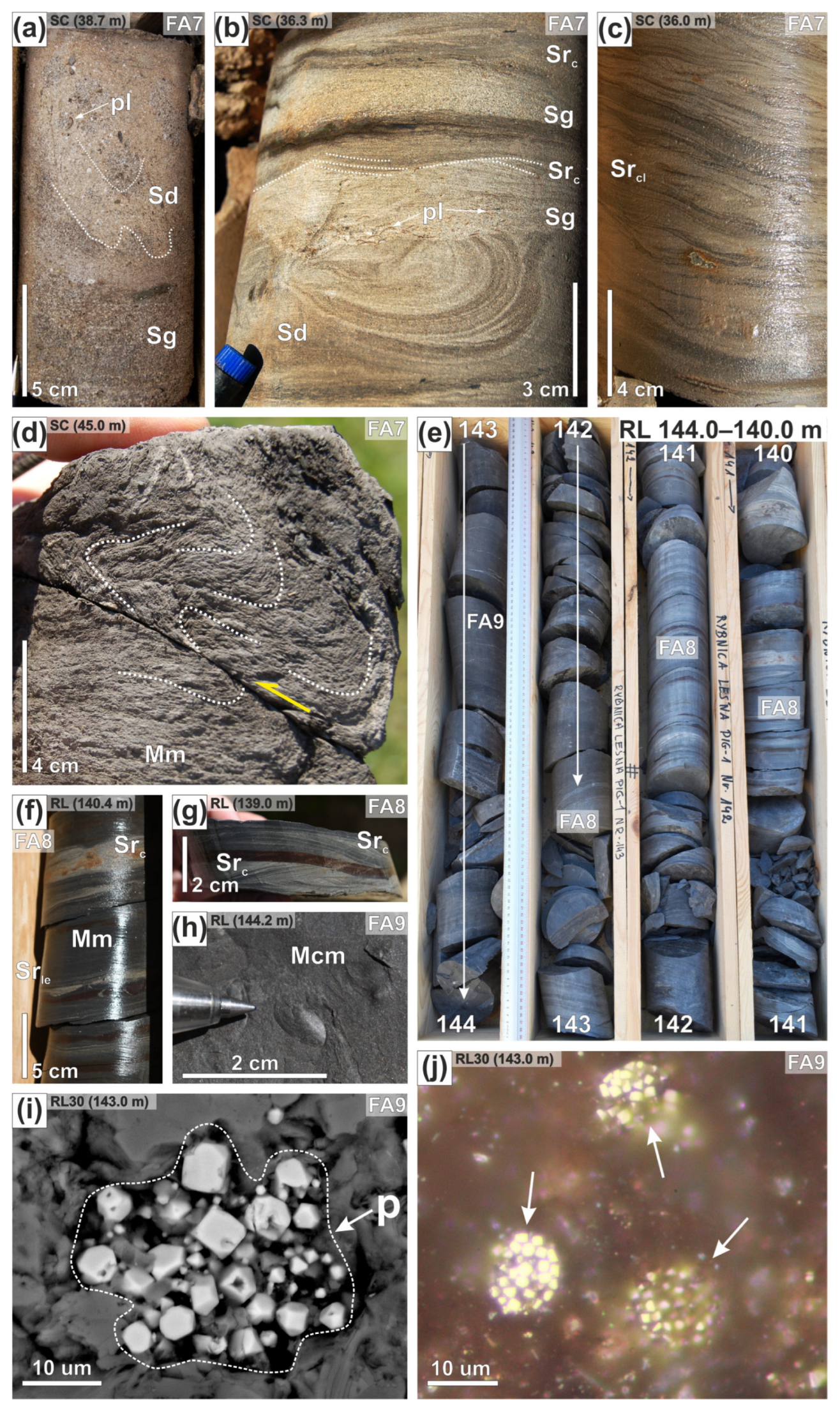
Facies Association FA7 comprises a variety of coarse-grained gravity-flow deposits typical of subaqueous environments. It commonly co-occurs with prodelta deposits of FA8 and is frequently recorded in the SC borehole (40–31.5 m, 28.4–27.2 m, and 24.9–21.6 m) as well as in the RL borehole (152.7–151.7 m and 150–148.9 m). The basal parts of FA7 intervals are dominated by coarse-grained grey sandstones (Sg), exhibiting both inverse and normal grading, with dispersed plant detritus (Figure 10a). These are accompanied by massive conglomerates (Gmm) and graded fine-grained conglomerates (Gmg), typically showing erosional bases and also containing scattered plant material. Deformation structures are common within the sandstones (Sd), including load casts, flame structures, and other soft-sediment deformation features indicative of rapid loading and liquefaction (Figure 10b). Beds composed of Sg and Sd lithofacies are frequently capped by ripple-laminated sandstones (Src) and climbing ripple-laminated sandstones (Srcl; Figure 10c). The uppermost parts of these gravity-flow units consist of massive grey mudstones (Mm), occasionally calcareous (Mm (c)), representing the fine-grained tops of individual beds. Within these mudstones, syndepositional folds and small-scale faults have been documented, most notably at ~45 m in the SC borehole (Figure 10d).
This facies association is interpreted as representing sedimentation on a subaqueous delta front and subaqueous fan, dominated by high-density turbidity currents and grain flows [83]. The presence of Sg sandstones and Gmm–Gmg conglomerates with erosional bases and inverse-to-normal grading indicates deposition from high-concentration density flows, consistent with the high-density turbidity current (HDTC) model of [146]. According to this model, thick, massive or graded sandstones form from traction carpets at the base of turbulent, sediment-laden flows, while overlying finer-grained units reflect transitional flow stages. The widespread occurrence of soft-sediment deformation structures (Sd) suggests rapid sediment accumulation on delta-front slopes, where liquefaction and deformation occur frequently. The ripple-laminated and climbing ripple-laminated beds (Src, Srcl) record waning flow stages during individual turbidity current events [147]. The massive mudstones (Mm, Mm (c)) represent suspension fallout during flow cessation. Collectively, FA7 captures multiple episodes of gravity-driven sedimentation associated with progradation into a subaqueous fan or prodelta setting.

4.2.8. Prodelta Facies Association (FA8)

Facies Association FA8 is dominated by fine-grained lithofacies of massive mudstones (Mm) and calcareous mudstones (Mm (c)), along with heterolithic clay-siltstone facies (Mh (c)) and predominantly of dark grey to black clayey mudstones rich in organic matter (‘black shales’; MCm) (Figure 10e,f). This facies association is frequently observed in the SC borehole, where it co-occurs with FA9 deposits within the intervals 57.2–56 m and 45.5–40 m. In the RL borehole, FA8 occurs in the intervals 151.7–150 m, 149–147 m, and 142.7–137.8 m. These fine-grained deposits commonly form thick beds that occasionally show evidence of turbidity-current activity. This is expressed by thin intercalations of massive sandstones (Sm), horizontally laminated sandstones (Sh), and normally graded sandstones (Sg) with sharp or erosional bases, locally capped by ripple-laminated sandstones (Src) and, in places, lenticular ripple lamination (Srle) (Figure 10f,g). Although these sandy interbeds are rare and discontinuous, their presence indicates episodic input from higher-energy flows into an otherwise low-energy depositional setting.
This facies association is interpreted as the product of low-energy sedimentation in a prodelta environment, potentially representing the distal fringe of a subaqueous fan system [145]. The dominance of organic-rich, finely laminated, fissile mudstones and claystones (MCm) together with heterolithic lithofacies (Mh (c)) reflects persistent suspension settling from the water column under quiet, oxygen-restricted conditions, likely below storm wave base. Deposition was occasionally interrupted by turbidity currents or low-density underflows that reached this part of the basin. The sporadic presence of sandstones (Sm, Sh, Sg) with grading or horizontal lamination is interpreted as evidence of rare distal high-energy underflows that punctuated the otherwise continuous hemipelagic or suspension-dominated sedimentation. Overall, FA8 records deposition in the most distal parts of the deltaic system or the outer zone of a subaqueous fan, characterized by low sedimentation rates, high organic-matter preservation potential, and only sporadic influence from gravity-driven flows.

4.2.9. Open Lake Facies Association (FA9)

Facies Association FA9 consists almost exclusively of grey to black mudstones with intercalations of very fine-grained sandstones (Figure 11). In the SC borehole, these deposits are recorded in the intervals 63–57.2 m and 56–45.5 m, where they co-occur with prodelta deposits (FA8). In the RL borehole, FA9 is present between 147 and 142.7 m. The dominant lithofacies is MCm—dark grey to black, fissile, organic-rich clayey mudstone, typically showing fine lamination and strong compaction, indicative of suspension fallout under low-energy depositional conditions. This facies is occasionally interbedded with grey, massive or weakly laminated mudstones of the Mm (c) and Mh (c) types, including heterolithic deposits of S/Mhg lithofacies (Figure 10e–g). Biogenic features are rare but locally include well-preserved horizons with bivalve shells of Anthracosia sp. (Figure 10h). Common diagenetic features include framboidal pyrite, thin sulfide-filled veinlets, and, more rarely, siderite cementation (Figure 10i,j). In the RL borehole, minor copper (Cu) staining has been noted along tectonic fracture surfaces. Trace bioturbation is locally present but remains subordinate.
This facies association is interpreted as recording sedimentation in a relatively deep, oxygen-deficient open lacustrine setting, located below the wave base. The presence of massive to weakly laminated, organic-rich mudstones, along with framboidal pyrite and limited bioturbation, indicates deposition under anoxic to dysoxic conditions, where bottom-water oxygen was consistently low. The absence of coarse-grained facies suggests a limited terrigenous sediment supply. The restricted occurrence of Anthracosia sp. supports the interpretation of a stratified, low-energy lake, where benthic colonization was limited to short intervals when oxygenation improved slightly, allowing temporary habitation by opportunistic, low-oxygen-tolerant organisms.

4.3. Inorganic Geochemistry and Magnetic Susceptibility

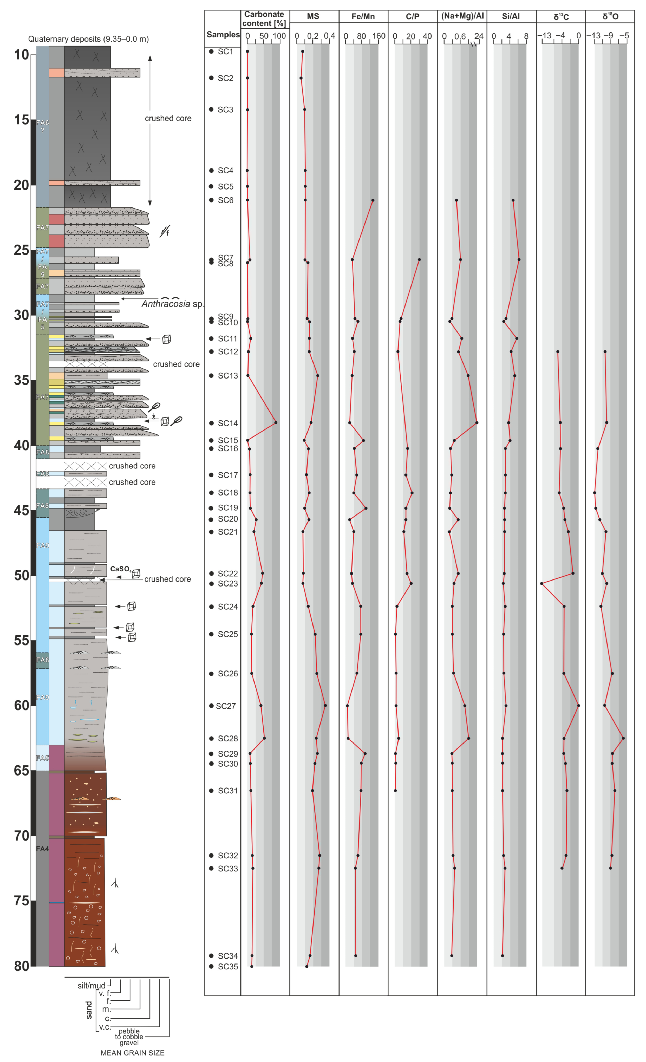
The carbonate content in the SC borehole exhibits a wide range, varying from undetectable to nearly 94% (Figure 12; Supplementary Table S2). Although low carbonate concentrations prevail throughout most of the core, two intervals—45.6–50.6 m and 60.0–62.7 m—are marked by elevated values. The highest CaCO3 concentration is recorded in a single sample (SC14), composed of porous dolomite (Figure 13). MS in the profile ranges from 0.063 to 0.338 and exhibits generally strong fluctuations. Higher MS values were observed within a continuous interval from 54.5 to 72.5 m. A positive correlation is noted between MS and CaCO3 content in the examined core.
The SC section exhibits variable Si/Al ratios, with a mean of 3.13, a median of 2.63, and values ranging from 2.16 to 6.23 (Figure 12). In the lower part of the core (below 39.5 m), the Si/Al ratio remains relatively stable and low, whereas higher values are observed in the upper part.
Fluctuations are also observed in (Na + Mg)/Al ratios, which have a mean of 1.24, a median of 0.34, and typically range between 0.20 and 0.90, with a distinct peak at 23.72 (sample SC14) (Figure 12; Supplementary Table S2). The distributions of (Na + Mg)/Al and CaCO3 are parallel. Elevated (Na + Mg)/Al values are associated with increased CaCO3 content and decreased Fe/Mn ratios. In the studied section, Fe/Mn ratios have a mean of 53.29, a median of 48.13, and values ranging between 15.35 and 132.45 (Figure 12; Supplementary Table S2). The SC section displays C/P values with a mean of 9.79, median of 6.98, and a range from 1.23 to 30.56 (Figure 12; Supplementary Table S2). Elevated values of C/P are typical to the interval between 40.4 and 50.6 m.
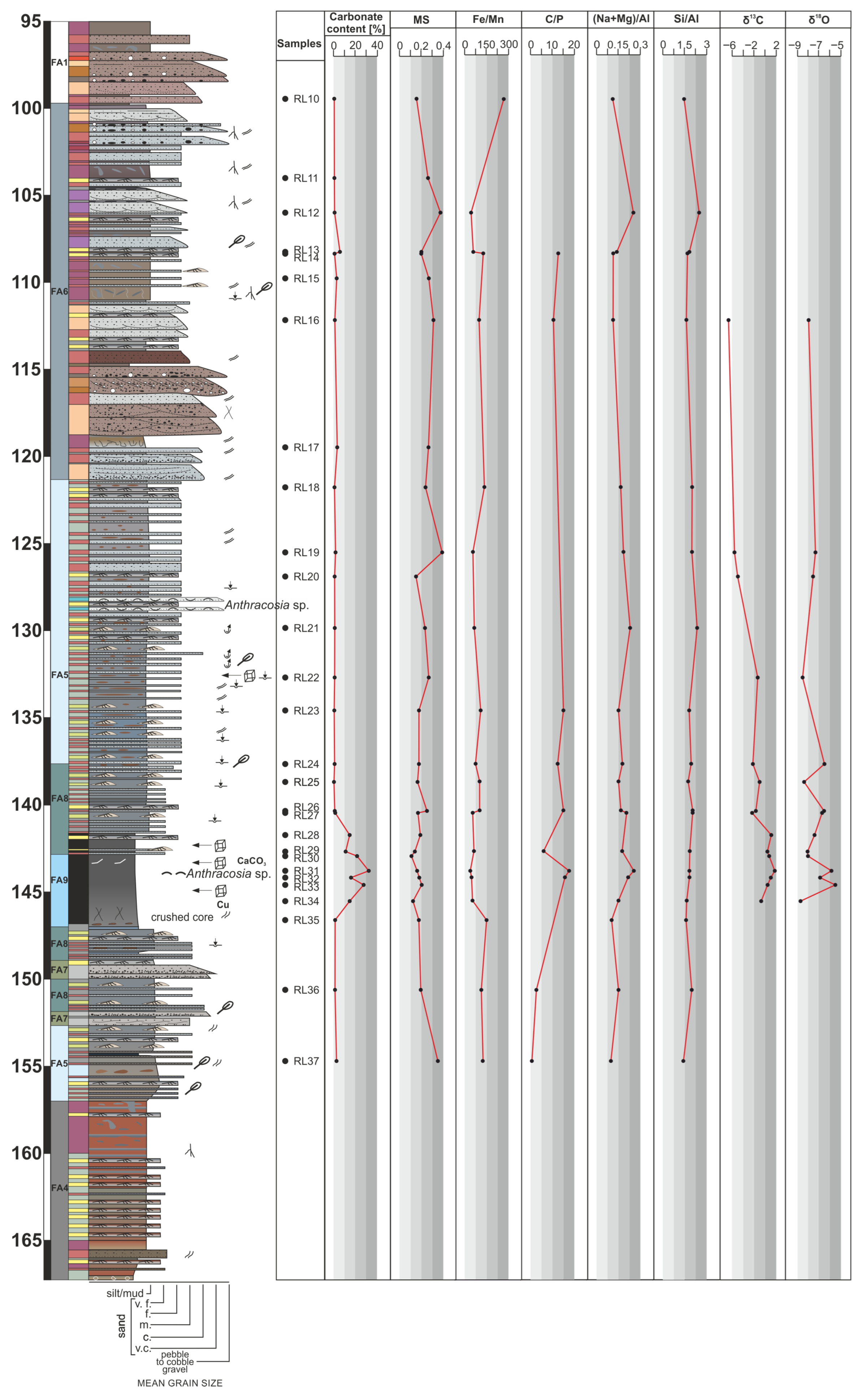
The carbonate content in the RL core shows a narrower range in comparison to SC profile, from 0.27% to 32.55% (Figure 14; Supplementary Table S2). For most of the sequence, carbonate concentrations remain low and stable, with a distinct interval of elevated values identified between 141.9 and 145.5 m. MS ranges from 0.108 to 0.389 (Figure 14; Supplementary Table S2), reflecting relatively low values and consistent variability throughout the core.
The Si/Al ratio in the RL core remains low and relatively stable, with a mean of 1.91, a median of 1.86, and a range from 1.46 to 2.51. The (Na + Mg)/Al ratio shows slight variation, ranging from 0.10 to 0.25. Compared to the SC section, the RL core displays higher and more variable Fe/Mn ratios, averaging 94.17, a median of 83.60, and a wider range from 39.77 to 267.65 (Figure 14; Supplementary Table S2).
The RL section presents slightly higher C/P values than SC, with a mean of 10.90, a median of 12.82, and a range from 1.02 to 17.46 (Figure 14; Supplementary Table S2). Overall, the carbonate-rich interval (141.9–145.5 m) is also characterized by elevated C/P ratios, which coincide with distinctly low MS values and reduced Fe/Mn ratios. The distributions of MS and Fe/Mn are parallel in the 150–130 m interval of the section. In the upper part of the section the MS increases are associated with elevated (Na + Mg)/Al ratios.

4.4. Bulk Carbonate Isotopic Composition

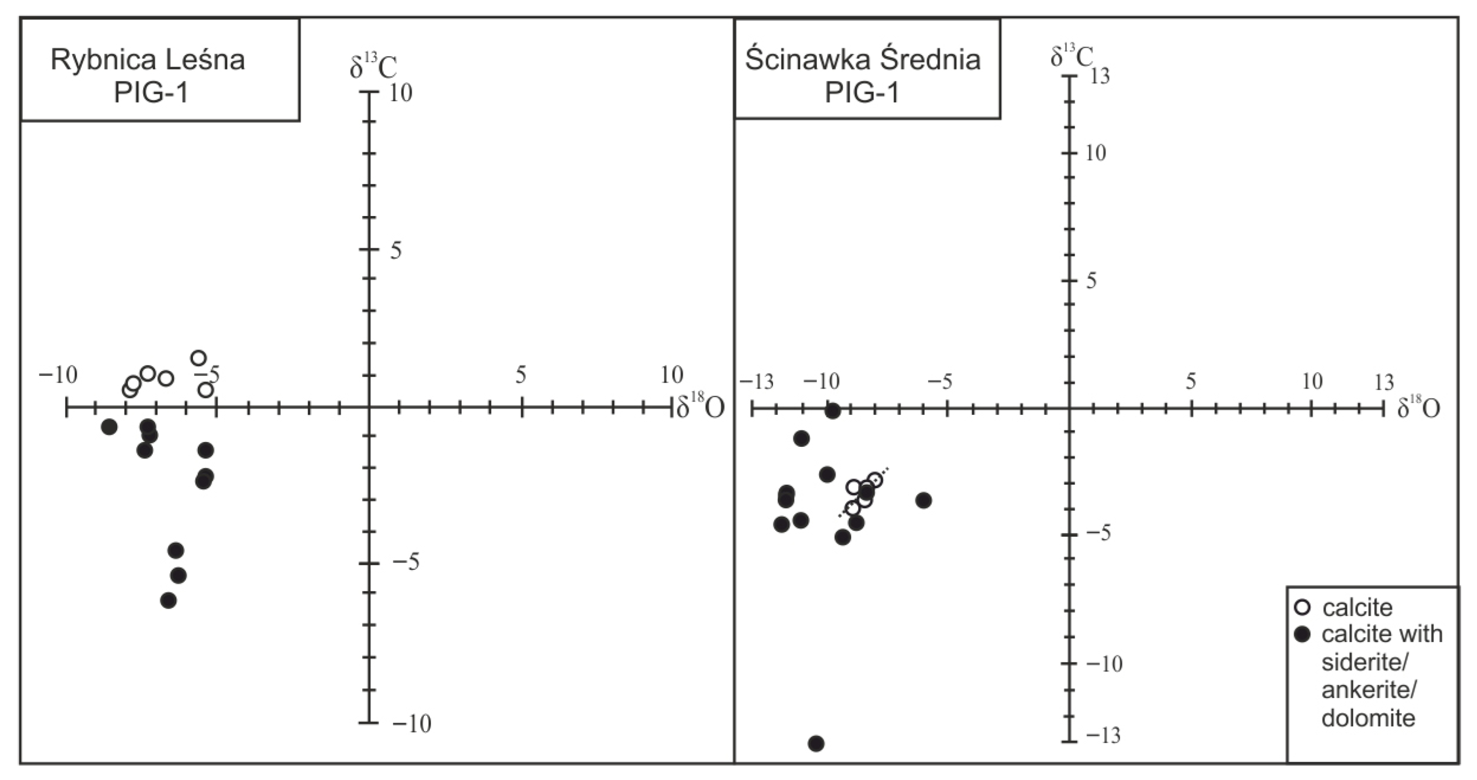
The δ13C values in the SC profile range from −13.06‰ to −0.12‰ (Figure 12; Supplementary Table S2), indicating a relatively wide variability in carbon isotopic composition throughout the section. The lowest recorded value (−13.06‰) stands out markedly from the general dataset as most of the δ13C values range around −4‰ to −3‰. The δ18O values range from −11.57 ‰ to −5.96 ‰ (Figure 12; Supplementary Table S2). At first, there appears to be no consistent or strong relationship between δ13C and δ18O values throughout the whole profile; however, a notable exception occurs within a restricted, singular interval in the lowermost part of the section, 63.75–72.5 m (Figure 12 and Figure 15; Supplementary Table S2).
The δ13C values in the RL profile vary between –6.61‰ and 1.79‰, displaying a distinct stratigraphic trend: values below 0‰ dominate the upper part of the interval (down to 142.0 m), whereas below this depth the δ13C values shift to consistently positive (>0‰). The δ18O values range from –8.78‰ to –5.48‰, indicating a moderate yet still significant degree of variation (Figure 14; Supplementary Table S2). No correlation between δ13C and δ18O is observed in any part of the core (Figure 15).

4.5. Organic Petrography

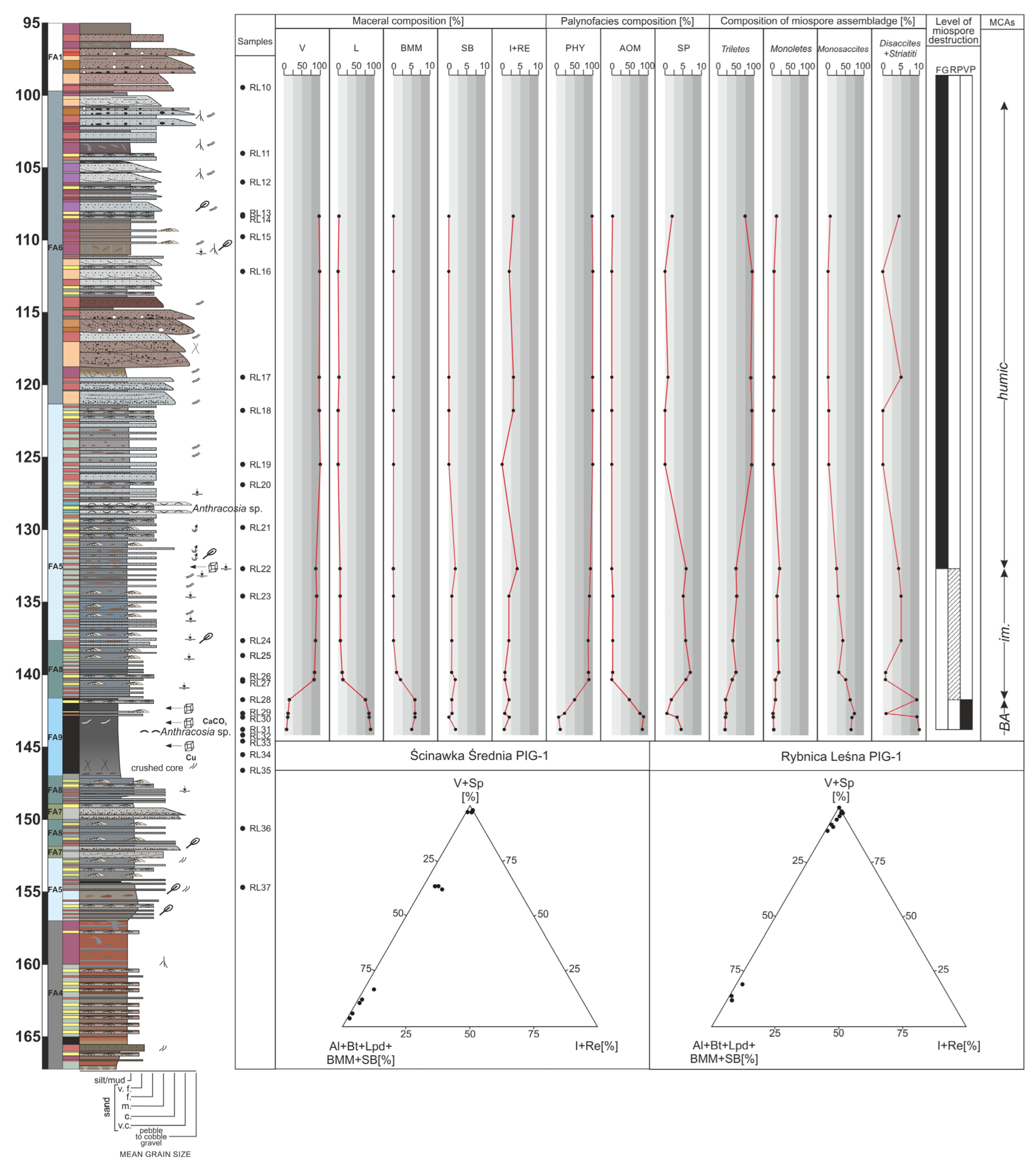
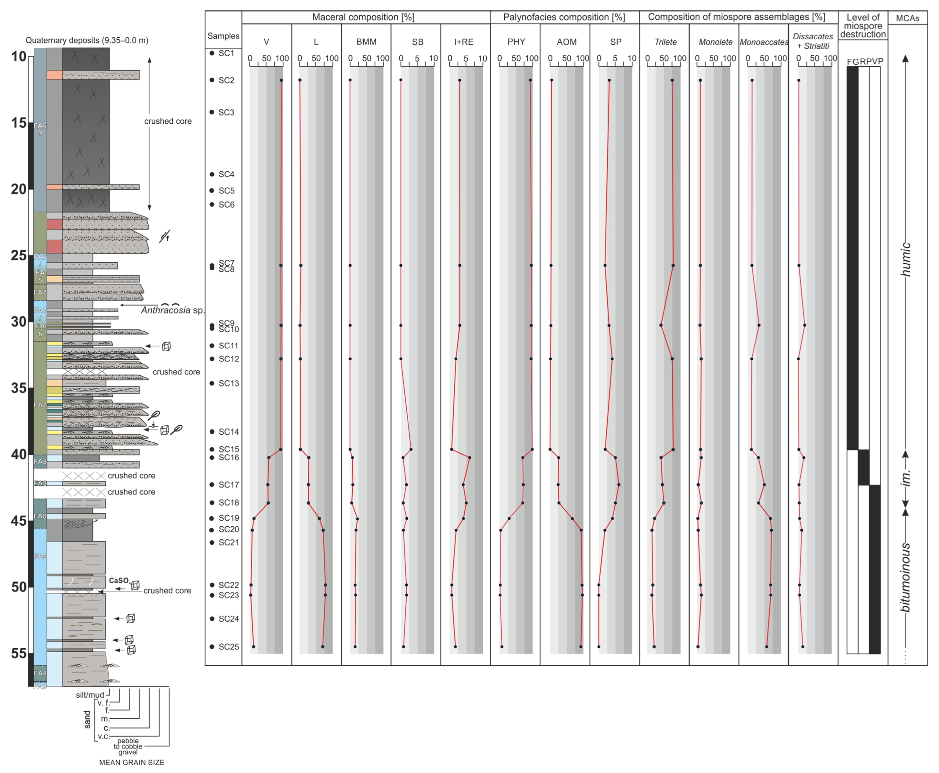
The organic matter studied by petrographic method consists of a variety of particles of different origins including macerals of three groups: vitrinite, liptinite, and inertinite (Figure 16). Additionally, solid bitumen and mineral-bituminous groundmass were observed in the LAS. The microscopic composition of the organic matter reveals the detailed composition of the organic matter, especially the diversity, abundances, thermal maturity, and intergranular distribution. These aspects show variations among the samples, indicating significant differences in the paleoenvironmental conditions.

Macerals

Terrestrial organic particles, identified as vitrinite and inertinite, are present in nearly all samples analyzed (Supplementary Tables S3 and S4). Vitrinite macerals are primarily derived from specific parts of higher plants [124,129]. Some vitrinite particles exhibit well-preserved structures, while others are rounded, indicating long-distance transport and redeposition (recycled or reworked vitrinite). Where present, reworked vitrinite ranges from trace amounts to 2 vol.%. In the LAS of both boreholes, vitrinite occurs mainly as collotelinite and collodetrinite, appearing as small fragments in the form of thin microbands, lenses, or grains. The most common vitrinite maceral is vitrodetrinite, which is dispersed as small particles within the mineral matrix. The smallest vitrodetrinite grains may occur alone or in combination with inertodetrinite to form humic debris. In the darkest shale samples, small amounts of hydrogen-rich vitrinite, referred to as “dark vitrinite” [126], are also present. The vitrinite macerals in the LAS exhibit a range of optical properties. Primary vitrinite typically appears grey, whereas reworked vitrinite is a lighter grey than primary vitrinite within the same sample. “Dark vitrinite” displays the darkest grey color among all vitrinite macerals. Under UV light, vitrodetrinite and collotelinite do not fluoresce, while collodetrinite may show weak dark brown fluorescence. “Dark vitrinite” may also exhibit brownish to brown fluorescence. Vitrinite content in the studied samples varies significantly, ranging from trace amounts up to 100 vol.% in the RL borehole (Supplementary Table S3), and up to 95 vol.% in the SC borehole (Figure 17 and Figure 18) (Supplementary Table S4).
Inertinite macerals identified in the shales are mainly inertodetrinite, derived from cell wall fragments of both fusinite and semifusinite. These small fragments form a detritus that is occasionally observed and is often associated with vitrinite, jointly forming humic debris. Inertinite macerals are interpreted as material subjected to long-distance transport, based on their fine size, fragmented structure, and degree of rounding. Inertinite is characterized by a lack of fluorescence and the highest reflectance values among the macerals observed in the LAS. Its content does not exceed 7 vol.% of the total organic matter (Figure 17 and Figure 18) (Supplementary Tables S3 and S4).
Liptinite represents a significant component of the maceral composition in the LAS from both boreholes. Liptinite content ranges from 1 to 84 vol.% in the RL borehole (Figure 17), and from 2 to 70 vol.% in the SC borehole (Figure 18). In the most hydrogen-rich shales, aquatic-origin liptinite dominates, comprising alginite, bituminite, and/or liptodetrinite (composed of small alginite fragments). Two alginite types were identified: lamalginite and telalginite [148,149].
Lamalginite occurs as short, sometimes anastomosing lamellae, commonly aligned parallel to bedding. It may be associated with mineral particles, isolated framboidal pyrite, or terrestrial macerals. Lamalginite exhibits light yellow fluorescence and is finely dispersed in the matrix. Brightly fluorescing lamalginite is not preserved at thermal maturities exceeding peak oil generation [150]. Lamalginite is the dominant alginite type in these shales. In contrast, telalginite, composed of larger, well-preserved unicellular algal bodies, is rare. It shows high-intensity yellow fluorescence, greater than that of lamalginite, and includes discoidal and elliptical forms. Alginite content does not exceed 8 vol.% of the organic matter (Supplementary Tables S3 and S4).
Bituminite, a structureless organic groundmass, is formed through bacterial degradation of algae and faunal plankton, along with bacterial biomass [129,148,151,152,153], typically under anoxic to suboxic conditions [128]. Bituminite appears as lenticels, irregular microlayers, mineral coatings, and infills between mineral grains. It is difficult to identify in reflected white light but fluoresces dark yellow to brown with relatively low intensity under UV light. Bituminite content reaches up to 71 vol.% in some samples (Supplementary Tables S3 and S4).
A key terrestrial liptinite maceral is sporinite, a significant component of the black shale type where aquatic liptinite dominates. Sporinite is represented mainly by thin-walled miospores, often observed as isolated forms within the bituminous-mineral groundmass or mineral matrix. It fluoresces dark yellow to light orange, noticeably darker than alginite. Sporinite contributes up to 7 vol.% of the organic matter (Figure 17 and Figure 18) (Supplementary Tables S3 and S4).
Liptodetrinite is identifiable only under UV light due to its fluorescent properties. It exhibits yellow to pale orange fluorescence and occurs as very small fragments of algal detritus (sometimes with residual shapes or uniform textures) and sporinite fragments. Though common, it appears in small amounts in the studied rocks.
In addition to the above macerals, the lacustrine deposits also contain solid bitumen (SB), especially in samples where aquatic material dominates. Solid bitumen content is negligible, not exceeding 2 vol.% of the total organic matter (Figure 17 and Figure 18) (Supplementary Tables S3 and S4).
Macerals in the LAS may form complexes with other organic or mineral components, particularly bituminite, which frequently occurs as a finely dispersed groundmass. In such cases, bituminite forms part of a bituminous-mineral matrix (BMM)—a composite of submicroscopic organic particles and mineral matter with flocculent or streaky textures. BMM is found in samples with abundant bituminite and is characterized by distinctive fluorescence properties. BMM content reaches up to 21 vol.% (Figure 17 and Figure 18) (Supplementary Tables S3 and S4).

4.6. Thermal Maturity Assessment

In this study, vitrinite reflectance was measured to assess the thermal maturity of organic matter. The vitrinite reflectance (VRo) values range from 0.53% to 0.70% in the fine-grained deposits from the RL borehole (Supplementary Table S3), and from 0.53% to 0.65% in the SC borehole (Supplementary Table S4). These results indicate that the organic matter within LAS is marginally to early mature [154,155].
The vitrinite reflectance data are supported by results from palynofacies analysis. The thermal maturation index, based on the coloration of Lycospora spores (ranging from yellow to orange–light brown), corresponds to levels 3–4 on the seven-point scale of [133,134]. These values of the miospore color index also indicate an early mature to mature stage of thermal evolution of the organic matter.

4.7. Palynofacies and Sporomorph Assemblages

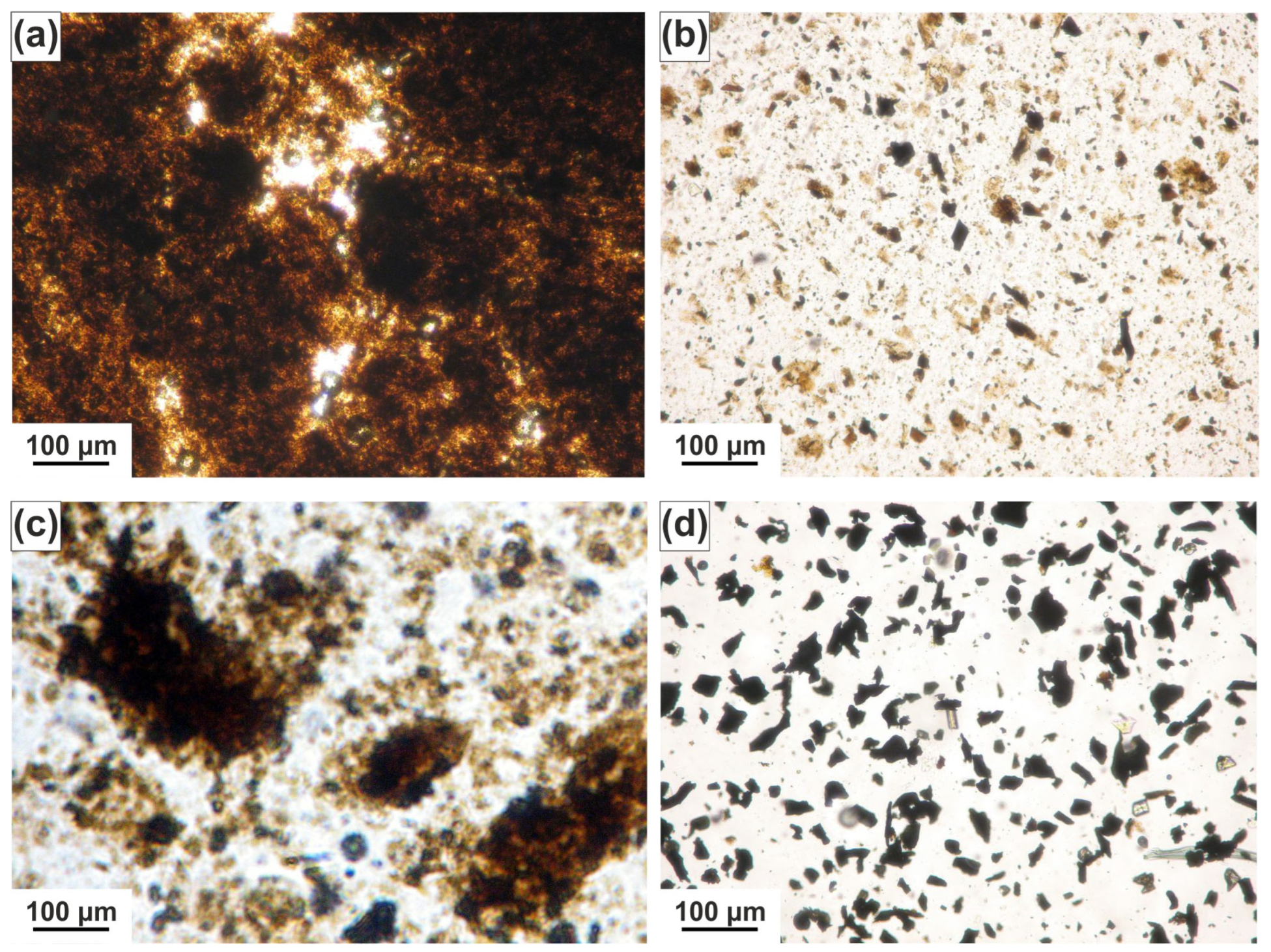
Three main groups of organic particles were identified in the studied palynofacies: phytoclasts, sporomorphs, and amorphous organic matter (AOM), occurring in variable proportions. Phytoclasts constitute an important and frequent component, although their abundance varies significantly. Most phytoclasts are black and opaque, with irregular outlines (Figure 19). Translucent phytoclasts, such as membranes and cuticles, are relatively rare. Their size is generally below 50 µm, although in two samples from the RL borehole (depths: 132.7–137.7 m and 108.35 m), significantly larger fragments reaching up to 300 µm were recorded.
Amorphous organic matter (AOM) forms a persistent and significant component in both studied borehole profiles. It appears as brown to grey-brown opaque aggregates in palynological slides and reaches up to 97% of the total organic content in some samples (Supplementary Tables S3 and S4). AOM typically co-occurs with phytoclasts, though their relative proportions vary. Samples rich in AOM usually contain only minor amounts of phytoclasts. This AOM-dominated palynofacies is especially typical of the lower intervals of both profiles, while upward in the succession, AOM abundance decreases and phytoclast content increases. The uppermost samples are dominated almost entirely by phytoclasts.
Sporomorphs (spores and pollen grains) occur in relatively low abundances, not exceeding 7% of the total palynofacies. They are typically orange to orange-brown in color, and their thermal alteration index (TAI), based on Batten’s scale, is estimated at 3–4. The preservation state of sporomorphs is variable and largely influenced by pyritization and mechanical destruction. Three levels of preservation were distinguished: fairly good (FG), where only a small portion of sporomorphs exhibit degradation; rather poor (RP); and very poor (VP), where most specimens show pyritization and damage. The degree of preservation correlates with AOM abundance, with the most pyritized and poorly preserved sporomorphs occurring in AOM-rich lower parts of both profiles. Better-preserved, pyrite-free sporomorphs are generally found in the upper parts of the sections.
Sporomorph assemblages are taxonomically diverse, comprising four main systematic groups. Triletes and Monoletes (spores) were produced by various pteridophytic plants (e.g., seed ferns, sphenopsids, lycopsids) that inhabited lowlands and wetlands. These spores were mainly water-transported. Pollen grains are represented by Monosaccites, Disaccites, and Striatiti, derived from gymnosperms that grew in more elevated and drier environments, and were wind-transported. All sporomorph groups are represented in each palynofacies type, though their relative proportions vary. Triletes and Monosaccites are dominant in all samples, often exceeding 75% of the assemblage. These two groups display an inverse abundance relationship—an increase in one is typically accompanied by a decrease in the other. The remaining groups—Monoletes, Disaccites, and Striatiti—are less frequent. A clear upward trend is observed in both profiles, with an increase in Triletes content and a concurrent decline in pollen grains, particularly Monosaccites and Disaccites. Monoletes occur sporadically and show no consistent stratigraphic pattern.

5. Interpretation and Discussion

5.1. Inorganic Geochemical and Magnetic Susceptibility Signatures in Fluvio-Lacustrine System Dynamics

Lacustrine bulk carbonate δ18O and δ13C values are highly sensitive to a complex set of environmental factors, such as seasonal temperature fluctuations, variations in the ratio of meteoric precipitation to evaporation (P/E), organic productivity within the lake, and changes in the hydrological regime (e.g., open vs. closed basin systems) [156,157,158]. The correlation of δ13C and δ18O in lacustrine carbonates has been widely used as a diagnostic proxy for assessing basin hydrology: a positive correlation typically indicates a closed lake system dominated by evaporation, whereas its absence suggests an open system with continuous inflow stabilizing isotopic composition [159,160,161].
The interpretation of lacustrine carbonate isotope data must consider the potential effects of diagenesis, as post-depositional processes can significantly modify the original isotopic signatures. Diagenetic alteration, often indicated by changes in carbonate mineralogy and the occurrence of siderite, ankerite, and/or dolomite, commonly results in isotopically lighter δ18O and δ13C values due to interaction with meteoric waters or the breakdown of organic matter. This may also lead to a homogenization of the isotopic signal, cover-ing primary environmental trends [157]. In our study, the isotopic data from both boreholes display substantial variation in δ-values in vertical sections and within individual beds. Such variability suggests that the original isotopic signatures have been at least partially preserved and are not the result of extensive diagenetic overprinting. This allows us to acknowledge the dataset as reliable, and the potential impact of diagenetically altered mineralogy is further discussed.
Magnetic susceptibility measurements are dimensionless values that represent the total amount of magnetic minerals (e.g., pyrite, siderite, ankerite, magnetite) present in the analyzed sample. Secondary processes such as metamorphism, demagnetization, and diagenesis can completely erase the original signal [162]. In general, higher values of MS can indicate higher detrital input or oxic conditions, while lower values can point to episodes with reduced detrital input and anoxic conditions. Indirectly, some climatic fluctuations can be deduced. Increased terrigenous input (higher MS) takes place during wetter periods, reduced clastic influx (low MS) happens during arid phases [163,164].
In the analyzed profile of the RL, isotopic values show no clear correlation (Figure 14 and Figure 15), which suggests a hydrologically open state of the lacustrine basin and/or constant riverine inflow, which is supported by a constant Si/Al ratio through the core. From the bottom of the section, δ13C values in the interval 142–144.9 m stand out from the rest with their positive values, which can suggest greater eutrophication of the lake [165,166], and it corresponds with the bituminous association linked with the deepwater zone, increased TOC values (up to 2.25 wt%) [43], and slightly increased C/P values. The distinction may also be visible due to the expected shift to more negative values due to the siderite presence in the interval above [43] (Figure 15). Low MS values here (IIA acc. [43]) may result from a limited supply of silt-sized detritus containing ferromagnetic minerals and anoxic conditions [163,164]. Importantly, this interval coincides with the development of FA8 (prodelta deposits) and FA9 (open-lake deposits), which is consistent with the sedimentological evidence.
Vertical variation in the δ18O values may indicate continuous riverine inflow to the basin. Sedimentary evidence also points to progressive shallowing of the lake, captured by the upward facies transition in the RL borehole—from FA8 (prodelta; 142.7–137.8 m), through FA5 (nearshore; 137.8–121.3 m), to FA6 and FA1 (delta plain and fluvial > 121.3 m). This trend is corroborated by the occurrence of humic and intermediate associations. Variations in the MS relatively high values in this interval additionally confirm the instant inflow to the lacustrine basin. Additionally, biogenic magnetite may also occur in diagenetic nodules, formed through biomineralization in oxic-suboxic transition zones [167]. Moreover, values can be elevated by the presence of pyrite and siderite in the intervals 137.7–144.9 m and 137.7–140.3, respectively [43].
Aridification is suggested by the Na + Mg/Al ratio during seasonal alteration and later, when the lake terminated (around 108.3 m). In the uppermost part of the profile, low MS values may result from arid conditions. Soil microbial activity, responsible for the formation of biogenic magnetite, is strongly restricted [168,169]. Limited surface runoff and erosion lead to fewer mineral particles (including magnetite) reaching the lake [164].
In the SC borehole, an interval (63.75–72.5 m) shows covariation of calcite isotopic values (Figure 15) together with lowered Si/Al ratios (Figure 12), indicating limited riverine inflow and enhanced evaporative concentration. This interval largely coincides with FA4 (playa-lake margin/coastal mudflat facies association), where episodic ponding on lake fringes or in floodplain depressions alternated with subaerial exposure and pedogenesis. The sedimentary characteristics of FA4 indicate the development of evaporite-prone conditions. Within the same interval, MS values increase despite reduced detrital input, plausibly reflecting in situ formation of magnetite in lake sediments by magnetotactic bacteria (e.g., Magnetospirillum magnetotacticum) under suitable redox conditions [167]. The mineralogical makeup (e.g., variable proportions of magnetic and non-magnetic phases) can also modulate the MS signal; therefore, MS should be interpreted jointly with Si/Al and lithofacies evidence.
Isotopic covariation is followed by a positive δ18O excursion indicative of increased evaporation and/or higher water temperatures—conditions typically associated with lower lake levels and a more closed hydrological state. The presence of pyrite and ankerite, alongside calcite, has been identified within the intervals 32.8–50.50 m and 63.90–40.40 m, respectively. This inference is consistent with the sedimentological and facies evidence: ankerite overlaps the FA9 open-lake intervals (63–57.2 m; 56–45.5 m) and the FA8 prodelta packages (57.2–56 m; 45.5–40 m). Pyrite spans the upper FA8 prodelta (45.5–40 m) and extends into the FA7 delta-slope deposits (40–31.5 m), reflecting dysoxic–anoxic bottom conditions in deeper/distal settings. Together, the mineral assemblages, δ18O excursion, and facies stacking (FA9–FA8–FA7) record a progressive shallowing-upward trend and delta progradation through this part of the section, transitioning from open-lake to prodelta to delta-slope settings.
In the section above 63.75 m, the covariance among isotopic proxies disappears (Figure 15), consistent with a permanent to seasonal river inflow. The decline in δ18O toward 43.6 m may also suggests increased meteoric input and higher lake levels [161]. These conditions favored the establishment of flora and fauna, as reflected by elevated C/P values, fluctuations in Fe/Mn indicative of changing redox states, and a bituminous maceral assemblage. Within this interval, two carbonate-enriched pulses (45.6–50.6 m and 60.0–62.7 m) co-vary with (Na + Mg)/Al. While such co-variation can signal drier episodes, it more plausibly records enhanced availability of Mg2+/Na+ and consequent precipitation of Mg-bearing carbonates (e.g., ankerite/dolomite). A second positive excursion in δ18O values above 43.6 m marks renewed evaporative concentration and coincides with a facies shift from bituminous to intermediate, and then humic associations. Despite the evaporative signal, multiple proxies indicate enhanced—likely pulsed—riverine input, evidenced by thin interbeds of coarser-grained siliciclastics (FA7—delta slope facies association), elevated Si/Al, and the occurrence of dolomite enclosing plant tissues (Figure 13) (consistent with shallow, productive waters and early diagenetic carbonate precipitation). The increased inflow is not mirrored by the magnetic susceptibility (MS) curve; this decoupling is plausibly due to arid-season suppression of microbial magnetite formation and reduced delivery of ferromagnetic silt, compounded by dilution effects from carbonates and organic matter.

5.2. Organic Matter Composition and Palynomorphs

The concept of organic facies has long been established in geological and coal petrography studies. Organic facies classification is based on the petrographic composition of organic matter, reflecting both the original vegetation input and depositional environment. Ref. [170] demonstrated that organic facies, kerogen types, and maceral assemblages are closely related to sedimentary conditions. In this study, the quantitative analysis of macerals in the LAS allowed for the identification of distinct organic associations. The classification follows the approach of [38,39,41], and was supported by palynofacies data to refine the environmental interpretation and origin of the organic matter. Three distinct organic associations within lacustrine-deltaic deposits were distinguished.

5.2.1. Bituminous Association (BA)

This association is dominated by bituminite, accompanied by lesser amounts of alginite (lamalginite and telalginite), dark vitrinite, liptodetrinite, and solid bitumen. Bituminous-mineral matrix (BMM) forms an important background component, comprising finely dispersed bituminite, alginite, liptodetrinite, and solid bitumen, and corresponds to the mineral-bituminous groundmass described by [151] or matrix bituminite [171]. This type of groundmass is commonly found in mudstones that serve as source rocks and has similar hydrocarbon generation potential to pure bituminite [124]. The occurrence of dark vitrinite supports a sapropelic depositional setting [126]. Among secondary-altered organics, solid bitumen was identified based on reflectance values lower than the vitrinite reflectance measured in the same samples (0.53–0.73% VRo), indicating that pyrobitumen is not present [172,173]. The palynofacies of the bituminous association is dominated by amorphous organic matter, with few phytoclasts or sporomorphs. Among sporomorphs, wind-transported pollen grains of the Monosaccites group, produced by upland Gymnosperms, dominate, while other groups occur only sporadically.
This association reflects deposition under low-energy, suboxic to anoxic conditions with high aquatic productivity and limited terrestrial input and is associated with prodelta and open lake facies associations (FA8 and FA9). It was identified in the depth interval 141.90–143.90 m in the RL borehole and at 44.85–54.50 m in the SC borehole profile.

5.2.2. Humic Association (HA)

The humic association is composed mainly of terrestrial macerals, such as vitrodetrinite, inertodetrinite, sporinite, and minor liptodetrinite. These macerals occur as thin bands, lenticles, or scattered fragments. Fluorescence, where observed, is weak and limited to liptinite components. The palynofacies of this association are dominated by phytoclasts, while amorphous organic matter is virtually absent. Sporomorphs are not very frequent, but those present are fairly well preserved. The most abundant are water-transported spores of ferns, sphenopsids, and lycopsids from wetland and lowland vegetation, primarily from the Triletes group, especially in the RL borehole. Monoletes spores are a constant but minor component. Gymnosperm pollen from the Monosaccites group is rare in the RL but more frequent in the SC boreholes. Similarly, the Disaccites group is slightly more common in the latter.
The humic association reflects deposition in higher-energy, more oxygenated environments with increased terrestrial input. It occurs between 108.35 and 125.50 m in the RL borehole and from 11.85 to 39.50 m in the SC borehole.

5.2.3. Intermediate Association (IA)

This association shows features of both bituminous and humic types, representing a transitional organic assemblage. Maceral composition includes both lipid-rich components (bituminite and alginite, BMM, solid bitumen) and terrestrial macerals (vitrodetrinite, sporinite). The palynofacies is also mixed, with phytoclasts dominating, but amorphous organic matter is also a stable and significant component. The sporomorph assemblage is intermediate, with similar proportions of Triletes and Monosaccites groups. Other groups are minor. This association suggests alternating terrestrial and aquatic input under fluctuating depositional conditions. It is most clearly developed in the SC profile between 40.20 and 43.60 m. In the RL borehole, the intermediate association is less distinct but likely occurs between 132.70 and 140.25 m, where samples show a mixed composition of liptinite, BMM, solid bitumen, and terrestrial macerals.
The distribution of maceral groups and organic matter types is illustrated on a ternary diagram (Figure 16), where the identified associations form distinguishable clusters. Samples from the RL profile are grouped in two main areas. One cluster, near the vitrinite + sporinite apex, reflects humic or terrestrially influenced intermediate compositions. The second cluster, near the alginite + bituminite + liptodetrinite + BMM + SB apex, corresponds to the bituminous association. In contrast, samples from the SC borehole show clearer separation among all three associations. Bituminous samples are located near the lipid-rich apex, humic samples align with the vitrinite + sporinite vertex, and intermediate samples occupy a central zone between these two poles. These patterns suggest distinct but overlapping depositional environments across both boreholes, reflecting variability in water energy, redox conditions, and organic matter sources within the fluvio-lacustrine system.

5.3. The Ludwikowice Formation: Depositional Models and Controls on the Late Carboniferous Fluvio-Lacustrine System in the Intra-Sudetic Basin

Reconstruction of the depositional history and controlling factors of the Ludwikowice Formation is based on a multiproxy approach that combines lithofacies analysis, borehole core observations, and geochemical, palynological, and organic matter (OM) data. These datasets are further integrated with basin-wide mapping of coarse-grained facies distribution and total formation thickness across the ISB. Geochemical proxies (including δ13C, δ18O, and elemental ratios such as Fe/Mn, Si/Al, and C/P) were used to assess variations in depositional processes, redox conditions, and sediment provenance, while petrographic analysis of organic matter assemblages provided insight into environmental conditions, aquatic productivity, and diagenetic pathways. The integration of these datasets allowed for the recognition of at least four distinct stages in the evolution of the Ludwikowice depositional system during the latest Carboniferous. Each stage represents a response to changing tectonic subsidence, sediment supply, hydrology of the basin, and climatic forcing, reflected in both the sedimentary record and organic geochemical signals preserved within the basin infill.
The initial phase of the deposition of the Ludwikowice Formation was characterized by a high-energy fluvial and alluvial system in a tectonically active basin (Figure 20a). The depositional architecture at the scale of the entire formation indicates pronounced structural control, with accumulation governed chiefly by fault-related subsidence. According to ref. [49], deposition of the Verneřovice Member, the stratigraphic equivalent of the Ludwikowice Formation in the Czech part of the ISB, began after a basin-wide intra-Stephanian hiatus and initially took place on a braided river plain dominated by bedload transport. In the study area, tectonic activity was concentrated along the Intra-Sudetic Fault and the Krajanów–Ścinawka Fault, which together defined the principal axis of extensional or transtensional deformation. The Domanów Fault, located along the northern margin, likely contributed to the pattern of differential subsidence. These structures created localized accommodation that favored rapid aggradation of coarse-grained fluvial- and alluvial fan systems. The sedimentary record documents repeated channel migration, avulsion, and bar accretion, producing thick, laterally amalgamated sandstone and conglomerate units of FA1. Fan aprons progressively coalesced with an axial river system occupying a depocenter oriented northwest to southeast and coincident with the Intra-Sudetic and Krajanów–Ścinawka fault zones. Along this axis, paleogeographic reconstructions indicate drainage directed toward the northwest and west (Figure 20a). Clastic material was sourced from surrounding uplifted massifs and delivered by multiple distributary systems that converged into the elongate axial zone [59]. Despite the emerging northwestward drainage, the basin likely remained internally drained through most of this phase. The overall architecture of coarse-grained lithofacies point to rapid aggradation in a fault-bounded continental setting with high sediment supply, limited accommodation in proximal sectors, and efficient sediment lateral dispersal.
The second phase in the evolution of the Ludwikowice Formation marks a significant retrogradation of the fluvial system, accompanied by the progressive development of overbank-dominated and playa-like environments across the ISB (Figure 20b). This transition was likely driven by a reduction in fluvial discharge and sediment supply, potentially coupled with climatic aridification. The reduction in riverine input was also indicated by isotopic covariation coupled with lowered Si/Al ratio. As active channel belts diminished in both scale and frequency, sedimentation became increasingly dominated by fine-grained overbank processes and sheetfloods operating across a broad, low-gradient basin floor. Fluvial activity became localized within shallow, ephemeral distributary channels that bifurcated and terminated across the floodplain. These floodplains were likely dry for most of the time and were only periodically inundated during flash floods. Sheetfloods and associated overbank processes produced a range of fine-grained lithofacies, including massive to bioturbated brown mudstones and fine-grained sandstones (Mm, Mmb, MSmb), which commonly exhibit mottling, root traces, carbonate nodules, and pedogenic horizons, all indicative of subaerial exposure and prolonged soil formation. These deposits are frequently interbedded with ripple-laminated sandstones (Src, occasionally Srcl), sandstone–mudstone couplets showing flaser to lenticular cross-bedding (Srle), and heterolithic deposits (S/Mhb) that reflect short-lived flood incursions followed by desiccation. Localized deformed intervals of Sd, characterized by floating mudstone clasts, load structures, and clastic dykes, suggest episodic high-energy sediment input and rapid dewatering of the floodplain surface. Thin, parallel-laminated aeolian sand sheets (Sx) also accumulated on exposed floodplain surfaces, recording wind reworking; although spatially and temporally restricted, these sands point to intermittent semi-arid conditions during this phase.
The fine-grained sandy and muddy deposits documented in the RL and SC boreholes, along with the overall fining of grain size toward the basin center, support the interpretation of extensive muddy to sandy floodplains, and shallow, ephemeral playa-lakes that developed in the eastern part of the ISB. The morphology of the depositional system progressively evolved toward that of a distributive fluvial system (DFS) [28,29,30,31,32,33,34], marked by declining lateral and vertical channel connectivity and a transition to overbank-dominated sedimentation in the distal basin sectors. Spatial patterns, such as the reduction in coarse-grained fluvial deposits toward the basin center and the concurrent increase in finer-grained lithofacies, align with characteristic DFS dynamics [174,175]. The lateral variation in grain size, supported by borehole data (Figure 4), reflects a continuous shift from proximal, channelized deposits to more distal settings dominated by overbank and lacustrine sedimentation.
The third phase in the evolution of the Ludwikowice Formation reflects the continued expansion of overbank and playa-type environments, culminating in the transgression of a lacustrine system driven by a regional base-level rise (Figure 20c). This phase marks the onset of a highstand lacustrine setting, evidenced by the interfingering of distal fluvial and lacustrine facies and the establishment of the so-called Anthracosia Lake [88]. As the lake progressively deepened and expanded across the central ISB, lacustrine processes became increasingly dominant—even in areas previously influenced by proximal fluvial systems, located in the easternmost part of the basin. The reduction in clastic input from fluvial sources, combined with temporary dysoxic conditions in deeper parts of the basin, promoted the accumulation and preservation of organic-rich mudstones with increased carbonate content. The organic matter was derived almost entirely from primary production, based on the maceral composition, and from emerged aquatic plants with only a minor contribution from terrestrial plants.
In the SC borehole, the transition from playa lake margin/coastal mudflat (FA4) to lacustrine settings is recorded by a gradual shift into FA9, composed almost entirely of grey to black mudstones intercalated with very fine-grained sandstones. The dominant lithofacies (Mm) comprises massive and laminated clayey mudstones, commonly enriched in both framboidal pyrite and accumulations of the euhedral crystals, and sulfide-filled veinlets. Subordinate facies include massive to weakly laminated mudstones (Mm, Mh) and heterolithic variants (Mh (g)). These sediments reflect suspension fallout under persistently low-energy, oxygen-deficient conditions, below wave base. Sparse bioturbation and occasional bivalve horizons with Anthracosia sp. further support deposition in a stratified freshwater to brackish lake with episodic benthic colonization during brief oxygenation events. Increased salinity was also confirmed by increased Sr/Ba ratio and EFNa. The presence of the kaolinite and its decreasing content upward the profile along with the appearance of gypsum in the upper part of the stages’ samples indicate the ongoing aridification of the climate. At the end of the stage, a positive excursion in δ18O values and an increase in the (Na + Mg)/Al ratio are marked, both of which indicate more arid conditions that may have initiated a fall in the base level.
In contrast, the RL borehole records a more gradual transition from marginal lacustrine (FA5) to open-lake settings (FA9). Alternating suspension fallout, wave activity, and storm reworking shaped this facies suite, with common bioturbation and Anthracosia sp. shell concentrations attesting to periodic colonization. Stratigraphically above, FA7 captures episodes of subaqueous gravity-driven sedimentation associated with delta front or subaqueous fan environments. These are characterized by coarse-grained, graded sandstones (Sg), conglomerates (Gmm, Gmg), and deformed beds (Sd), overlain by ripple-laminated sandstones (Src, Srcl) and capped by massive to calcareous mudstones (Mm, Mm (c)) with sideritic lenses. Geochemical proxies indicate intensified chemical alteration linked to a humid climate, supported by the sideritic lenses formed through synsedimentary or early diagenetic reduction in ferric (oxyhydr)oxides produced by terrestrial weathering under warm and humid conditions. Siderite occurrence vanishes with the end of the stage III pointing to a more arid climate [43].
The fourth depositional phase, represented by the uppermost part of the Ludwikowice Formation, is marked by a distinct regressive sequence (Figure 20d). It reflects a transition from relatively deep lacustrine conditions to progressively shallower, deltaic and fluvial environments. This regressive trend is recorded in a progradational succession that begins with prodeltaic (FA8), delta front (FA7), and nearshore deposits (FA5), which gradually transition into fully developed deltaic (FA6) and fluvial facies (FA1). At the beginning of this phase, sediments were primarily sourced from the eastern, northern, and southeastern margins of the basin. Detrital material was transported by fluvial systems into nearshore and deltaic zones, where delta lobes formed along the prograding shoreline. A shift in the origin of the OM composition from algal to terrestrial is also visible. As lake levels continued to fall, deltaic systems prograded further into the basin, gradually infilling the lake and leading to the establishment of predominantly fluvial conditions. This phase reflects a climatic or tectonically driven base-level fall, leading to increased sediment supply and reduced accommodation space. Ultimately, this transition sets the stage for the fluvial-dominated deposition characteristic of the Krajanów Formation [79], signaling the end of widespread lacustrine sedimentation in the Intra-Sudetic Basin.
In the SC profile, the higher gypsum content compared to stage III along with the OM derived from the arid-resistant plants can indicate more arid conditions. Despite the diagenetic overprint observed in the precepitated dolomite layer, the presence of well-preserved plant tissues within the sample (Figure 13c) provides a furter evidence for a coastal depositional environment. These organic remains, embedded within the dolomitic matrix, indicate that the sediment was deposited in a setting where terrestrial input played a significant role. The coexistence of dolomitized carbonate and plant debris suggests a dynamic depositional environment with periodic flooding, high evaporation, and fluctuating salinity. In the RL profile, aridification trend is marked by geochemical proxies and declining kaolinite content in the upper part of the profile, which suggest a decrease in the chemical weathering that tends to be more intense in humid climates [43]. Organic matter from this interval represents a humic association that was deposited in a coastal zone.
The facies architecture and sedimentological features of the Ludwikowice Formation align with the typical depositional evolution of extensional rift basins, as outlined by [176]. Stratigraphic successions in such settings often begin with fluvial deposits, succeeded by lacustrine strata—frequently organic-rich black shales formed under anoxic conditions—which then grade upward into shallower lacustrine or playa deposits. The final stage is marked by a return to fluvial sedimentation as the basin becomes overfilled. The Ludwikowice Formation broadly follows this model. Initial fluvial deposits, linked to renewed subsidence within the basin, were gradually replaced—both vertically and laterally—by overbank facies, and subsequently by lacustrine strata, including organic-rich black shales. A later phase of tectonic uplift in the source areas triggered the influx of prodeltaic, subaqueous delta front/subaqueous fan and deltaic deposits. This evolution culminated in a return to fluvial setting during the basin’s overfilling stage, marked by the onset of the Krajanów Formation. In the ISB, the tectonic activity was likely linked to strike-slip faulting along the Intra-Sudetic- and Krajanów–Ścinawka fault systems, with sinistral displacements inferred for the latest Carboniferous to early Permian in the northeastern Bohemian Massif [177,178,179].
Comparable tectono-sedimentary patterns have been identified in coeval non-marine basins of the Bohemian Massif [21,50,83,107,108,178,180,181,182] and several post-Variscan continental basins across Central and Western Europe (see overview in [183]). Notable examples include the Graissessac–Lodève and Autun basins (France) [176,184,185,186,187], the transboundary Lorraine–Saar–Nahe Basin [188,189,190], as well as the Thuringian Forest and Saale basins [191,192] (Germany). These widespread similarities suggest a shared set of controlling factors operating at the regional scale, including tectonically induced accommodation space and prolonged crustal subsidence, which acted in combination with climate variability to modulate both sediment supply and the nature of depositional environments across these basins [50,59,79,180,182].
Climatic conditions during the Carboniferous–Permian transition were characterized by pronounced seasonality across tropical Pangea [49,193]. This strongly seasonal climate, associated with a long-term aridification trend beginning around the Carboniferous–Permian boundary, significantly influenced sediment supply, runoff dynamics, and patterns of biotic turnover. In the ISB and other contemporaneous basins within the Bohemian Massif, the shift toward drier conditions resulted in the decline of peat-forming wetlands [49,182,183] and promoted the development of non-perennial to ephemeral fluvial systems [79,80].

5.4. Late Carboniferous Palaeogeography of the Intra-Sudetic Basin

During the late Carboniferous, the ISB developed as a semi-enclosed segment of a system of extensional post-orogenic basins that formed during the waning stages of the Variscan orogeny in the Bohemian Massif. Situated at the eastern margin of the Pilsen–Trutnov Basin Complex [49,50], the ISB evolved in response to tectonic reactivation and uplift of the surrounding metamorphic and crystalline massifs. These elevated source areas supplied detritus from multiple directions, feeding the basin with clastic material throughout its evolution.
On the eastern margin of the basin, the Góry Sowie Massif (GSM) constituted a major source area for the late Carboniferous ISB (Figure 20). The proportion of sediment supply derived from the present-day mountainous part of the GSM versus its fore-Sudetic segment, however, remains uncertain. Geophysical data indicate that the fore-Sudetic part of the GSM exposes deeper structural levels, approximately 5 km below those presently uplifted in the Sudetic Block [194]. This suggests that the present-day configuration of the Fore-Sudetic and Sudetic blocks, dissected by the Sudetic Marginal Fault, may have been reversed during the Carboniferous [103]. The progressive thickening of the Ludwikowice Formation towards the southwest, adjacent to the GSM (Figure 3b), further suggests partial burial of the now-elevated GSM beneath sediments of this formation. This structural and topographic configuration implies that both the Fore-Sudetic Block and, to a lesser extent, parts of the mountainous GSM contributed gneissic detritus to the late Carboniferous ISB. At the same time, portions of the Sudetic Block were likely buried beneath the accumulating deposits of the Ludwikowice Fm., and the boundary of the source area may have been controlled by NW–SE-trending faults that define the present tectonic grabens within the GSM [179].
To the southeast of the GSM, additional source areas for the southern and southeastern ISB margins were provided by the Bardo Unit and the Kłodzko Metamorphic Complex, with further input from the Orlica and Bystrzyca Metamorphic complexes [135] (Figure 20). These southern sources are today partly exposed at the surface and buried beneath Upper Cretaceous deposits of the Upper Nysa Kłodzka Graben (Figure 1a). Evidence for a source area located in the vicinity of the Duszniki–Gorzanów Fault is provided by the increase in coarse-grained material north of this structure, suggesting sediment supply from that direction to the basin despite the absence of exposures and borehole data. This hypothesis is further supported by north and northeast paleotransport directions recorded in the younger deposits of the Radków Formation in this part of the basin. To the north, the late Carboniferous ISB was supplied by the Kaczawa Metamorphic Complex (Figure 20), as evidenced by Ludwikowice conglomerates containing clasts of low-grade metamorphic rocks derived from this unit. From the northwest, additional detritus was contributed by the Rudawy Janowickie Metamorphic Complex. Sediment supply from the west and southwest remains less clear. The limited occurrence of coarse-grained deposits in the western sector of the basin suggests that it represented a more distal zone, receiving only minor clastic input. Consequently, there is no evidence for significant tectonic or erosional activity along the western basin margin during the late Carboniferous to early Permian, including the Poříčí–Hronov fault zone in the Czech part of the basin. This relationship may imply a paleogeographic connection to the Krkonoše–Piedmont Basin, where the Semily Formation, occurring west of this fault, is regarded as lithostratigraphically equivalent to the Ludwikowice Formation [50].
One of the key unresolved questions concerns the hydrological character of the ISB during the late Carboniferous. Specifically, it remains uncertain whether the basin functioned as an endorheic (internally drained) system or as an exorheic (externally drained) one. Closely related is the issue of whether a drainage connection toward the northwest existed, potentially linking the Intra-Sudetic and North-Sudetic basins. Paleocurrent data from the eastern part of the ISB indicate predominantly west- to southwest-directed flow (Figure 3d). However, the possibility of a northwest-directed outflow during the early stages of Ludwikowice Formation deposition—suggested in earlier paleogeographic reconstructions [59]—cannot be entirely ruled out. Sedimentological and borehole evidence from the northern part of the basin (Figure 3d) suggests the development of a substantial alluvial–fluvial fan prograding from the north (i.e., from the direction of the North-Sudetic Basin). This interpretation is supported by both the high abundance of coarse-grained deposits in the northern part of the basin and paleocurrent indicators, which together strongly argue against an open connection between the Intra-Sudetic and North-Sudetic basins during this stage. It is more likely that such a connection may have been established later, during the deposition of the Słupiec and Radków formations (Chełmsko Śląskie Beds) [94]. Based on paleocurrent data and borehole evidence, the ISB during the deposition of the Ludwikowice Formation is best interpreted as an endorheic, internally drained system. However, a potential hydrological connection to the west—toward the Krkonoše–Piedmont Basin—cannot be entirely excluded.
Importantly, the present-day distribution of the Ludwikowice Formation is largely the result of Late Cretaceous–early Paleogene tectonic inversion that reshaped the structural architecture of the ISB [99]. This deformation event, associated with significant uplift and reactivation of pre-existing extensional/transtensional fault systems, led to the exhumation and erosion of previously buried strata, thereby fragmenting the original areal extent of the formation. It is therefore likely that Ludwikowice deposits once extended farther to the north, northeast, east, and southeast, covering regions now occupied by the Góry Sowie Massif, the Nowa Ruda Massif, the Kłodzko Metamorphic Complex, and the Bardo Unit (Figure 1a). Petrographic evidence strongly supports this interpretation [135]. In particular, deposits of the Ludwikowice Formation exposed near the Nowa Ruda Massif notably lack gabbroic clasts, which are characteristic of this ophiolitic suite. This absence suggests that the Nowa Ruda Massif did not constitute a positive topographic element during late Carboniferous sedimentation, but rather became emergent during Late Cretaceous to early Paleogene deformation, in a manner comparable to the northwestern part of the Kłodzko Metamorphic Massif. As a result, the current outcrop pattern of the Ludwikowice Formation is highly discontinuous, structurally modified, and represents only a remnant of its former distribution (Figure 3).

6. Conclusions

(1)
The Ludwikowice Formation constitutes a latest Carboniferous (late Gzhelian) fining-upward megacyclothem in the fault-controlled intramontane Intra-Sudetic Basin (NE Bohemian Massif, SW Poland) that records a transition from proximal, coarse-grained fluvial deposits to distal, fine-grained, organic-rich lacustrine facies, collectively referred to as the Lower Anthracosia Shale (LAS).
(2)
The formation displays pronounced lateral thickness variability, generally thickening from the east, northeast, and southeast toward central–eastern depocenters aligned NW–SE along the Intra-Sudetic and Krajanów–Ścinawka faults. It typically overlies the fluvial Glinik Formation but locally rests directly on metamorphic basement in the south. Maximum thickness exceeds 600 m near Nowa Ruda, while it thins to approximately 50–100 m along the western basin margin (east of the Hronov–Poříčí Fault and the Lubawka–Czech sector) and is entirely absent in the southernmost part of the basin. The Lower Anthracosia Shale exhibits a similar distribution pattern, reaching up to ~135 m in the Nowa Ruda area and thinning westward to ~5–10 m in distal western sectors. Coarse-grained facies diminish toward the basin interior, though localized coarse aprons are developed in the northeastern (up to ~90% of the succession), eastern and southern sectors of the basin.
(3)
The nine lithofacies associations (FA1–FA9) identified within the Ludwikowice Formation represent a late Carboniferous fluvio-lacustrine depositional system of the Intra-Sudetic Basin. These include fluvial (FA1), sandy to muddy floodplain (FA2), aeolian (FA3), playa lake margin/coastal mudflat (FA4), nearshore (FA5), delta plain (FA6), subaqueous delta front and subaqueous fan (FA7), prodelta (FA8), and open lake (FA9) deposits. Collectively, they document a four-stage evolution from proximal, high-energy fluvial and alluvial environments (FA1), through transitional floodplain and lake-margin settings (FA2–FA6), to distal lacustrine conditions (FA7–FA9), and finally a return to fluvial sedimentation (FA1). The facies architecture and stratigraphic stacking broadly conform to the typical depositional evolution of extensional rift basins, particularly those that developed in equatorial Pangea after the Variscan orogeny.
(4)
Geochemical, isotopic, and petrological data support the interpretation of evolving redox and hydrological regimes within the basin. Carbon and oxygen isotope compositions from lacustrine carbonates show intervals of both correlated and uncorrelated behavior, suggesting alternating phases of hydrologically open and closed lake conditions. These patterns, together with Si/Al and Fe/Mn ratios, indicate changes in freshwater influx, evaporative concentration, and nutrient supply. Magnetic susceptibility data further support variations in detrital input and microbial magnetite formation, pointing to climatic oscillations between wetter and more arid phases. The coupling of sedimentological and geochemical proxies allows for a detailed reconstruction of basin dynamics and lake-level changes.
(5)
The composition and distribution of organic matter reveal three distinct petrographic associations: bituminous, humic, and intermediate, each reflecting specific environmental conditions. Bituminite- and alginite-rich intervals correspond to deepwater, anoxic depositional settings with high aquatic productivity and minimal clastic dilution, while humic associations dominated by vitrinite with smaller sporinite content represent more oxygenated, higher-energy conditions with substantial terrestrial input. These associations correlate well with interpreted lithofacies, maceral assemblages and palynofacies types, confirming a strong linkage between organic matter preservation, redox gradients, and depositional subenvironments.
(6)
Altogether, the Ludwikowice Formation provides a well-preserved archive of late Carboniferous paleoenvironmental change within a tectonically active continental basin. Its vertical organization and internal facies variability reflect a sensitive response to both allogenic (tectonic and climatic) and autogenic (depositional) controls. The results presented in this study offer new insights into the processes governing fluvio-lacustrine sedimentation in intramontane (endorheic) basins and contribute to broader models of basin evolution, lake dynamics, and organic matter accumulation during the Late Paleozoic.

Supplementary Materials

The following supporting information can be downloaded at: https://www.mdpi.com/article/10.3390/min15101077/s1, Table S1: List of boreholes used during this study, with coordinates provided in the WGS 84 and Poland 92 coordinate systems. Table S2: Geochemical data collection for RL and SC samples: magnetic susceptibility (MS), carbonate content, δ18O and δ13C of bulk carbonates, elemental proxies: Fe/Mn, C/P, (Na + Mg)/Al, Si/Al. Table S3: Maceral contents (vol%), vitrinite reflectance measurements and TOC (wt.%) of the Lower Anthracosia Shale samples from the Rybnica Leśna PIG 1 (RL) borehole. Maceral contents determined by point count; vol%: volume percent (mineral-matter-free); V—vitrinite; L—liptinite: Sp—sporinite, Al—alginite, Bt—bituminite, Lpd—liptodetrinite, SB—solid bitumen, BMM—bituminous-mineral matrix; IN—inertinite; Re—recycled vitrinite; Ro— mean vitrinite reflectance (%); *—only single vitrinite fragments are present; +—mainly humic debris; tr—traces. Table S4: Maceral contents (vol%), vitrinite reflectance measurements (%), and TOC (wt.%) of the Lower Anthracosia Shale samples from the Ścinawka Średnia PIG 1 borehole. Maceral contents determined by point count; vol%: volume percent (mineral-matter-free); V—vitrinite; L—liptinite: Sp—sporinite, Al—alginite, Bt—bituminite, Lpd—liptodetrinite, SB—solid bitumen, BMM—bituminous-mineral matrix; IN—inertinite; Re—recycled vitrinite; Ro— mean vitrinite reflectance (%); *—sample without macerals; **—only single vitrinite fragments are present; +—mainly humic debris; tr—traces.

Author Contributions

Conceptualization, A.K., J.D.-G., G.J.N., A.G.-N., U.W., M.F. and P.W.-T.; methodology, A.K., J.D.-G., G.J.N., A.G.-N. and P.W.-T.; regional background, sedimentological and facies analysis, A.K.; petrographic analyses, J.D.-G. and M.F.; geochemistry, J.D.-G. and P.W.-T.; organic petrology, G.J.N.; palynology, A.G.-N.; validation, A.K., J.D.-G., G.J.N., A.G.-N. and P.W.-T.; investigation, A.K., J.D.-G., G.J.N., A.G.-N., U.W., M.F. and P.W.-T.; writing—original draft preparation, A.K., J.D.-G., G.J.N., A.G.-N. and P.W.-T.; writing—review and editing, A.K., J.D.-G., G.J.N. and A.G.-N.; visualization, A.K., J.D.-G., U.W. and M.F.; supervision, A.K., G.J.N., A.G.-N. and P.W.-T.; funding acquisition, A.K. All authors have read and agreed to the published version of the manuscript.

Funding

This research was carried out as part of the statutory project no. 61.2601.2500.00.0 of the Polish Geological Institute—National Research Institute (for A.K. and G.J.N.); and as part of the grant from the Faculty of Geography and Geology under the Strategic Programme Excellence Initiative at the Jagiellonian University, Kraków (J.D.-G. and P.W.-T.).

Data Availability Statement

The original contributions presented in this study are included in the article and Supplementary Materials. Further inquiries can be directed to the corresponding authors.

Acknowledgments

We would like to thank four Reviewers, whose constructive comments and suggestions have contributed significantly to the improvement of the original manuscript. We gratefully acknowledge the Czech Geological Survey for providing access to borehole data from its repository. We also thank Adam Ihnatowicz (PGI-NRI) for granting access to archival profiles of Polish boreholes. Wojciech Bobiński (PGI-NRI) is acknowledged for providing access to archival petrographic thin sections. The authors have reviewed and edited the output and take full responsibility for the content of this publication.

Conflicts of Interest

The authors declare no conflicts of interest.

Abbreviations

The following abbreviations are used in this manuscript:
ISBIntra-Sudetic Basin
GSMGóry Sowie Massif
LASLower Anthracosia Shale

References

  1. Ezquerro, L.; Liesa, C.L.; Simón, J.L.; Luzón, A. Sequence stratigraphy in continental endorheic basins: New contributions from the case of the northern extensional Teruel Basin. Sediment. Geol. 2025, 481, 106868. [Google Scholar] [CrossRef]
  2. Marenssi, S.A.; Limarino, C.O.; Schencman, L.J.; Ciccioli, P.L. Tectonic and geomorphic controls on the lacustrine deposits of the Neogene Vinchina Basin, northwestern Argentina. J. Sediment. Res. 2020, 90, 250–267. [Google Scholar] [CrossRef]
  3. Ciccioli, P.L.; Marenssi, S.A.; Amidon, W.H.; Limarino, C.O.; Kylander-Clark, A. Alluvial to lacustrine sedimentation in an endorheic basin during the Mio-Pliocene: The Toro Negro Formation, central Andes of Argentina. J. South Am. Earth Sci. 2018, 84, 69–87. [Google Scholar] [CrossRef]
  4. Garcia-Castellanos, D. Long-term evolution of tectonic lakes: Climatic controls on the development of internally drained basins. In Tectonics, Climate, and Landscape Evolution; Geological Society of America: Boulder, CO, USA, 2006; ISBN 978-0-8137-2398-3. [Google Scholar]
  5. Ventra, D.; Nichols, G.J. Autogenic dynamics of alluvial fans in endorheic basins: Outcrop examples and stratigraphic significance. Sedimentology 2014, 61, 767–791. [Google Scholar] [CrossRef]
  6. Carroll, A.R.; Bohacs, K.M. Stratigraphic classification of ancient lakes: Balancing tectonic and climatic controls. Geology 1999, 27, 99–102. [Google Scholar] [CrossRef]
  7. Nichols, G. Fluvial Systems in Desiccating Endorheic Basins. In Sedimentary Processes, Environments and Basins; Nichols, G., Williams, E., Paola, C., Eds.; Wiley: Hoboken, NJ, USA, 2007; pp. 569–589. ISBN 978-1-4051-7922-5. [Google Scholar] [CrossRef]
  8. Nichols, G. Endorheic Basins. In Tectonics of Sedimentary Basins; Busby, C., Azor, A., Eds.; Wiley: Hoboken, NJ, USA, 2011; pp. 621–632. ISBN 978-1-4051-9465-5. [Google Scholar] [CrossRef]
  9. Yapiyev, V.; Sagintayev, Z.; Inglezakis, V.; Samarkhanov, K.; Verhoef, A. Essentials of Endorheic Basins and Lakes: A Review in the Context of Current and Future Water Resource Management and Mitigation Activities in Central Asia. Water 2017, 9, 798. [Google Scholar] [CrossRef]
  10. Andrews, S.D.; Hartley, A.J. The response of lake margin sedimentary systems to climatically driven lake level fluctuations: Middle Devonian, Orcadian Basin, Scotland. Sedimentology 2015, 62, 1693–1716. [Google Scholar] [CrossRef]
  11. Folkestad, A.; Steel, R.J. The alluvial cyclicity in hornelen basin (Devonian Western Norway) revisited: A multiparameter sedimentary analysis and stratigraphic implications. In Norwegian Petroleum Society Special Publications; Elsevier: Amsterdam, The Netherlands, 2001; Volume 10, pp. 39–50. [Google Scholar] [CrossRef]
  12. Andrews, S.D.; Guo, L. Mixed clastic-carbonate lake margin systems: An example from the Triassic of East Greenland. Depos. Rec. 2025, 11, 675–697. [Google Scholar] [CrossRef]
  13. Olsen, P.E.; Kent, D.V.; Cornet, B.; Witte, W.K.; Schlische, R.W. High-Resolution Stratigraphy of the Newark Rift Basin (Early Mesozoic, Eastern North America). Geol. Soc. Am. Bull. 1996, 108, 40–77. [Google Scholar] [CrossRef]
  14. Donaghy, E.E.; Umhoefer, P.J.; Eddy, M.P.; Miller, R.B.; LaCasse, T. Stratigraphy, age, and provenance of the Eocene Chumstick basin, Washington Cascades; implications for paleogeography, regional tectonics, and development of strike-slip basins. GSA Bull. 2021, 133, 2418–2438. [Google Scholar] [CrossRef]
  15. Nichols, G.J.; Hirst, J.P. Alluvial fans and fluvial distributary systems, Oligo-Miocene, northern Spain; contrasting processes and products. J. Sediment. Res. 1998, 68, 879–889. [Google Scholar] [CrossRef]
  16. Crowell, J.C. Introduction to geology of Ridge Basin, southern California. In Evolution of Ridge Basin, Southern California: An Interplay of Sedimentation and Tectonics; Geological Society of America: Boulder, CO, USA, 2003; ISBN 978-0-8137-2367-9. [Google Scholar]
  17. Bohacs, K.; Carroll, A.; Neal, J.; Mankiewicz, P. Lake-basin type, source potential, and hydrocarbon character: An integrated sequence-stratigraphic–geochemical framework. In Lake Basins Through Space and Time; AAPG Studies in Geology: Tulsa, OK, USA, 2000; Volume 46, pp. 3–33. [Google Scholar]
  18. Benavente, C.A.; Bohacs, K.M. Advances in limnogeology: The lake-basin-type model revisited 25 years after… anomalies, conundrums and upgrades. Depos. Rec. 2024, 10, 748–792. [Google Scholar] [CrossRef]
  19. Tourtelot, H.A. Black shale—Its deposition and diagenesis. Clays Clay Miner. 1979, 27, 313–321. [Google Scholar] [CrossRef]
  20. Kruge, M.A.; Hubert, J.F.; Jay Akes, R.; Meriney, P.E. Biological markers in Lower Jurassic synrift lacustrine black shales, Hartford Basin, Connecticut, U.S.A. Org. Geochem. 1990, 15, 281–289. [Google Scholar] [CrossRef]
  21. Martínek, K.; Blecha, M.; Daněk, V.; Franců, J.; Hladíková, J.; Johnová, R.; Uličný, D. Record of palaeoenvironmental changes in a Lower Permian organic-rich lacustrine succession: Integrated sedimentological and geochemical study of the Rudník Member, Krkonoše Piedmont Basin, Czech Republic. Palaeogeogr. Palaeoclimatol. Palaeoecol. 2006, 230, 85–128. [Google Scholar] [CrossRef]
  22. Liu, B.; Lü, Y.; Meng, Y.; Li, X.; Guo, X.; Ma, Q.; Zhao, W. Petrologic characteristics and genetic model of lacustrine lamellar fine-grained rock and its significance for shale oil exploration: A case study of Permian Lucaogou Formation in Malang Sag, Santanghu Basin, NW China. Pet. Explor. Dev. 2015, 42, 656–666. [Google Scholar] [CrossRef]
  23. Sun, N.; He, W.; Zhong, J.; Gao, J.; Sheng, P. Lithofacies and shale oil potential of fine-grained sedimentary rocks in lacustrine basin (Upper Cretaceous Qingshankou Formation, Songliao Basin, northeast China). Minerals 2023, 13, 385. [Google Scholar] [CrossRef]
  24. Wang, M.; Xue, H.; Tian, S.; Wilkins, R.W.T.; Wang, Z. Fractal characteristics of Upper Cretaceous lacustrine shale from the Songliao Basin, NE China. Mar. Pet. Geol. 2015, 67, 144–153. [Google Scholar] [CrossRef]
  25. Zou, C.; Zhu, R.; Chen, Z.-Q.; Ogg, J.G.; Wu, S.; Dong, D.; Qiu, Z.; Wang, Y.; Wang, L.; Lin, S.; et al. Organic-matter-rich shales of China. Earth-Sci. Rev. 2019, 189, 51–78. [Google Scholar] [CrossRef]
  26. Zhang, K.; Liu, R.; Liu, Z.; Li, L.; Wu, X.; Zhao, K. Influence of palaeoclimate and hydrothermal activity on organic matter accumulation in lacustrine black shales from the Lower Cretaceous Bayingebi Formation of the Yin’e Basin, China. Palaeogeogr. Palaeoclimatol. Palaeoecol. 2020, 560, 110007. [Google Scholar] [CrossRef]
  27. Fisher, J.A.; Nichols, G.J. Interpreting the stratigraphic architecture of fluvial systems in internally drained basins. J. Geol. Soc. 2013, 170, 57–65. [Google Scholar] [CrossRef]
  28. Nichols, G.J.; Fisher, J.A. Processes, facies and architecture of fluvial distributary system deposits. Sediment. Geol. 2007, 195, 75–90. [Google Scholar] [CrossRef]
  29. Weissmann, G.S.; Hartley, A.J.; Nichols, G.J.; Scuderi, L.A.; Olson, M.; Buehler, H.; Banteah, R. Fluvial form in modern continental sedimentary basins: Distributive fluvial systems. Geology 2010, 38, 39–42. [Google Scholar] [CrossRef]
  30. Hartley, A.J.; Weissmann, G.S.; Nichols, G.J.; Warwick, G.L. Large Distributive Fluvial Systems: Characteristics, Distribution, and Controls on Development. J. Sediment. Res. 2010, 80, 167–183. [Google Scholar] [CrossRef]
  31. Davidson, S.K.; Hartley, A.J.; Weissmann, G.S.; Nichols, G.J.; Scuderi, L.A. Geomorphic elements on modern distributive fluvial systems. Geomorphology 2013, 180–181, 82–95. [Google Scholar] [CrossRef]
  32. Weissmann, G.S.; Hartley, A.J.; Scuderi, L.A.; Nichols, G.J.; Davidson, S.K.; Owen, A.; Atchley, S.C.; Bhattacharyya, P.; Chakraborty, T.; Ghosh, P.; et al. Prograding Distributive Fluvial Systems—Geomorphic Models and Ancient Examples. In New Frontiers in Paleopedology and Terrestrial Paleoclimatology: Paleosols and Soil Surface Analog Systems; Driese, S.G., Nordt, L.C., Eds.; SEPM (Society for Sedimentary Geology): Broken Arrow, OK, USA, 2013; pp. 131–147. ISBN 978-1-56576-322-7. [Google Scholar]
  33. Moscariello, A. Alluvial fans and fluvial fans at the margins of continental sedimentary basins: Geomorphic and sedimentological distinction for geo-energy exploration and development. Geol. Soc. Lond. Spec. Publ. 2018, 440, 215–243. [Google Scholar] [CrossRef]
  34. Carraro, D.; Ventra, D.; Moscariello, A. Anatomy of a fluvial paleo-fan: Sedimentological and architectural trends of the Paleocene–Eocene Wasatch–Colton System (western Uinta Basin, Utah, U.S.A.). J. Sediment. Res. 2023, 93, 370–412. [Google Scholar] [CrossRef]
  35. Nemec, W.; Porębski, S.J.; Teisseyre, A.K. Explanatory notes to the lithotectonic molasse profile of the Intra-Sudetic Basin, Polish part (Sudety Mts., Carboniferous–Permian). In Tectonic Regime of Molasse Epochs; Schwab, G., Ed.; Veröff. Zentralinst. Erde: Potsdam, German, 1982; pp. 267–278. [Google Scholar]
  36. Lorenc, S. Rozprzestrzenienie, litologia i orientacyjne cechy geochemiczne czarnych łupków Sudetów (Distribution, lithology and approximate geochemical features of the Sudetes black shales). Prace Geologiczno-Mineralogiczne. Z badań nad mineralizacją rudną regionu sudeckiego 1993, 33, 179–208, (In Polish with English Summary). [Google Scholar]
  37. Yawanarajah, S.R.; Kruge, M.A.; Mastalerz, M.; Sliwinski, W. Organic geochemistry of Permian organic-rich sediments from the Sudetes area, SW Poland. Org. Geochem. 1993, 20, 267–281. [Google Scholar] [CrossRef]
  38. Nowak, G. Microscopic identification and classification of organic matter of the Upper Carboniferous Anthracosia Shales, Intra-Sudetic Depression, southwestern Poland. Geol. Q. 1998, 42, 41–58. [Google Scholar]
  39. Nowak, G.J. Comparative studies of organic matter petrography of the late Palaeozoic black shales from southwestern Poland. Int. J. Coal Geol. 2007, 71, 568–585. [Google Scholar] [CrossRef]
  40. Wójcik-Tabol, P.; Dąbek, J.; Nowak, G. Wstępna charakterystyka mineralogiczna czarnych łupków antrakozjowych z obszaru synklinorium śródsudeckiego (Preliminary mineralogical characteristics of the Anthracosia Shales from the Intra-Sudetic Synclinorium). Przegląd Geol. 2021, 69, 389–392, (In Polish with English Summary). [Google Scholar] [CrossRef]
  41. Nowak, G.; Górecka-Nowak, A.; Karcz, P. Petrographic, palynological and geochemical recognition of dispersed organic matter in the black Anthracosia Shales (Sudetes, South-West Poland). Geol. Q. 2022, 66, 36. [Google Scholar] [CrossRef]
  42. Dąbek-Głowacka, J.; Wójcik-Tabol, P.; Nowak, G.; Wendorff-Belon, M.; Marynowski, L. Łupki antrakozjowe niecki śródsudeckiej w świetle wskaźników geochemii organicznej—Wstępne wyniki analizy bituminów (The Anthracosia Shales from the Intra-Sudetic Basin in the light of organic geochemistry proxies—Preliminary results of bitumen study). Przegląd Geol. 2023, 71, 269–273, (In Polish with English Summary). [Google Scholar] [CrossRef]
  43. Dąbek-Głowacka, J.; Wójcik-Tabol, P.; Nowak, G.J. Influence of late Carboniferous–early Permian climate change on the sedimentary evolution: A case study of the lacustrine Lower Anthracosia Shales (Intra-Sudetic Basin, SW Poland). Geol. Q. 2024, 68, 5. [Google Scholar] [CrossRef]
  44. Franke, W.; Żelaźniewicz, A. Variscan evolution of the Bohemian Massif (Central Europe): Fiction, facts and mroblems. Gondwana Res. 2023, 124, 351–377. [Google Scholar] [CrossRef]
  45. Catalán, J.R.M.; Schulmann, K.; Ghienne, J.-F. The Mid-Variscan Allochthon: Keys from correlation, partial retrodeformation and plate-tectonic reconstruction to unlock the geometry of a non-cylindrical belt. Earth-Sci. Rev. 2021, 220, 103700. [Google Scholar] [CrossRef]
  46. Mazur, S.; Aleksandrowski, P.; Kryza, R.; Oberc-Dziedzic, T. The Variscan Orogen in Poland. Geol. Q. 2006, 50, 89–118. [Google Scholar]
  47. Aleksandrowski, P.; Kryza, R.; Mazur, S.; Pin, C.; Zalasiewicz, J.A. The Polish Sudetes: Caledonian or Variscan? Trans. R. Soc. Edinb. Earth Sci. 1999, 90, 127–146. [Google Scholar] [CrossRef]
  48. Cháb, J.; Breiter, K.; Fatka, O.; Hladil, J.; Kalvoda, J.; Šimůnek, Z.; Štorch, P.; Vašíček, Z.; Zajíc, J.; Zapletal, J. Outline of the Geology of the Bohemian Massif: The Basement Rocks and Their Carboniferous and Permian Cover; Czech Geological Survey: Prague, Czech Republic, 2010.
  49. Opluštil, S.; Šimůnek, Z.; Zajíc, J.; Mencl, V. Climatic and biotic changes around the Carboniferous/Permian boundary recorded in the continental basins of the Czech Republic. Int. J. Coal Geol. 2013, 119, 114–151. [Google Scholar] [CrossRef]
  50. Opluštil, S.; Schmitz, M.; Kachlík, V.; Štamberg, S. Re-assessment of lithostratigraphy, biostratigraphy, and volcanic activity of the late Paleozoic Intra-Sudetic, Krkonoše-Piedmont and Mnichovo Hradiště basins (Czech Republic) based on new U–Pb CA-ID-TIMS ages. Bull. Geosci. 2016, 91, 399–432. [Google Scholar] [CrossRef]
  51. Porębski, S. Sedymentacja utworów górnego dewonu i dolnego karbonu depresji Świebodzic (Sudety Zachodnie) (Świebodzice succesion (Upper Devonian-Lowest Carboniferous): A prograding, mass flow dominated fan-delta complex). Geol. Sudet. 1981, 16, 101–192, (In Polish with English Summary). [Google Scholar]
  52. Wajsprych, B. Allochtoniczne skały paleozoiczne w osadach wizeńskich Gór Bardzkich (Sudety) (Allochthonous Paleozoic rocks in the Visean of the Bardzkie Mts. (Sudetes)). Ann. Soc. Geol. Pol. 1978, 48, 99–127, (In Polish with English Summary). [Google Scholar]
  53. Don, J.; Gotowała, R. Tectonic evolution of the Late Cretaceous Nysa Kłodzka Graben, Sudetes, SW Poland. Geol. Sudet. 2008, 40, 51–63. [Google Scholar]
  54. Don, B.; Don, J. Geneza Rowu Nysy na tle badań wykonanych w okolicy Idzikowa (Notes on the origin of the Nysa Graben). Acta Geol. Pol. 1960, 10, 71–106, (In Polish with English Summary). [Google Scholar]
  55. Turnau, E.; Żelaźniewicz, A.; Franke, W. Middle to early late Viséan onset of late orogenic sedimentation in the Intra-Sudetic Basin, West Sudetes: Miospore evidence and tectonic implication. Geol. Sudet. 2002, 34, 9–16. [Google Scholar]
  56. Awdankiewicz, M.; Kurowski, L.; Mastalerz, K.; Raczyński, P. The Intra-Sudetic Basin—A record of sedimentary and volcanic processes in late- to post-orogenic tectonic setting. Geolines 2003, 16, 165–183. [Google Scholar]
  57. Teisseyre, A.K. Sedymentologia i paleogeografia kulmu starszego w zachodniej części niecki śródsudeckiej (Sedimentology and palaeogeography of the Kulm alluvial fans in the western Intrasudetic Basin (Central Sudetes, SW Poland)). Geol. Sudet. 1975, 9, 7–89, (In Polish with English Summary). [Google Scholar]
  58. Teisseyre, A.K. Charakterystyka sedymentologiczna kulmu z Ciechanowic i paleogeografia najniższego kulmu niecki śródsudeckiej (Sedimentology of the Kulm of Ciechanowice and palaeogeography of the Lowest Kulm of the Intrasudetic Basin). Geol. Sudet. 1971, 5, 237–280, (In Polish with English Summary). [Google Scholar]
  59. Wojewoda, J.; Mastalerz, K. Ewolucja klimatu oraz allocykliczność i autocykliczność sedymentacji na przykładzie osadów kontynentalnych górnego karbonu i permu w Sudetach (Climate evolution, allo-and autocyclicity of sedimentation: An example from the Permo-Carboniferous continental deposits of the Sudetes, SW Poland). Przegląd Geol. 1989, 432, 173–180, (In Polish with English Summary). [Google Scholar]
  60. Mastalerz, K. Deposits of high-density turbidity currents on fan-delta slopes: An example from the Upper Visean Szczawno Formation, Intrasudetic Basin, Poland. Sediment. Geol. 1995, 98, 121–146. [Google Scholar] [CrossRef]
  61. Wojewoda, J. Upper Cretaceous littoral-to-shelf succession in the Intrasudetic Basin and Nysa Trough, Sudety Mts. Obszary Źródłowe: Zapis w Osadach 1997, 1, 81–96. [Google Scholar]
  62. Dziedzic, K.; Teisseyre, A.K. The Hercynian molasse and younger deposits in the Intra-Sudetic Depression, SW Poland. Neues Jahrbuch für Geologie und Paläontologie 1990, 179, 285–305. [Google Scholar] [CrossRef]
  63. Kowalski, A. Late Cretaceous palaeogeography of NE Bohemian Massif: Diachronous sedimentary successions in the Wleń Graben and Krzeszów Brachysyncline (SW Poland). Ann. Soc. Geol. Pol. 2021, 91, 1–36. [Google Scholar] [CrossRef]
  64. Żakowa, H. Górny wizen dolnokarbońskiej Niecki Śródsudeckiej (Upper Visean of the Lower Carboniferous Intrasudetic Basin). Geol. Q. 1958, 2, 609–625, (In Polish with English Summary). [Google Scholar]
  65. Muszer, J. Trace fossils from the Mississippian of the Piaskowa Góra section (the Intra-Sudetic Basin, SW Poland). Ann. Soc. Geol. Pol. 2020, 90, 195–213. [Google Scholar] [CrossRef]
  66. Nemec, W. Warstwy wałbrzyskie (dolny Namur) w Zagłębiu Wałbrzyskim: Analiza aluwialnej sedymentacji w basenie węglowym (Wałbrzych Beds (Lower Namurian, Wałbrzych Coal Measures): Analysis of alluvial sedimentation in a coal basin). Geol. Sudet. 1984, 19, 7–73, (In Polish with English Summary). [Google Scholar]
  67. Mastalerz, K. Sedymentacja warstw żaclerskich (Westfal) w niecce wałbrzyskiej (Sedimentation of the Žacler Formation (Westphalian) in the Wałbrzych Basin). Acta Univ. Wratislaviensis Pr. Geol.-Mineral. 1996, 52, 21–85, (In Polish with English Summary). [Google Scholar]
  68. Kurowski, L. Fluvial sedimentology of the Biały Kamień Formation (Upper Carboniferous, Sudetes, Poland). Geol. Sudet. 1998, 31, 69–77. [Google Scholar]
  69. Dziedzic, K. Sedymentacja i paleogeografia utworów górnokarbońskich w niecce śródsudeckiej (Sedimentation and paleogeography of the Upper Carboniferous formations in the Intra-Sudetic Basin). Geol. Sudet. 1971, 5, 7–66, (In Polish with English Summary). [Google Scholar]
  70. Bossowski, A.; Ihnatowicz, A. Palaeogeography of the Upper Carboniferous coal-bearing deposits in NE part of the Intra-Sudetic Depression. Geol. Q. 1994, 38, 231–248. [Google Scholar]
  71. Ihnatowicz, A. Warunki sedymentacji formacji z Glinika (Basen Śródsudecki) (Depositional conditions of the Glinik Formation (Intra-Sudetic Basin)). Biul. Państwowego Inst. Geol. 2005, 415, 101–151, (In Polish with English Summary). [Google Scholar]
  72. Bossowski, A.; Ihnatowicz, A. Palaeogeography of the uppermost Carboniferous and lowermost Permian deposits in the NE part. Geol. Q. 1994, 38, 709–726. [Google Scholar]
  73. Miecznik, J.B. The Upper Silesian and Lower Autunian from NE limb of the Intra-Sudetic Depression. Biul. Państwowego Inst. Geol. 1989, 363, 5–39. [Google Scholar]
  74. Miecznik, J.B. Diastrophic-sedimentary evolution of the Intra-Sudetic Basin in the late Silesian to early Autunian. Przegląd Geol. 1988, 36, 211–214, (In Polish with English Summary). [Google Scholar]
  75. Dziedzic, K. Utwory dolnopermskie w Niecce Śródsudeckiej (Lower Permian formations in the Intra-Sudetic Basin). Stud. Geol. Pol. 1961, 6, 1–121, (In Polish with English Summary). [Google Scholar]
  76. Tásler, R.; Čadková, Z.; Dvořák, J.; Fediuk, F.; Chaloupský, J.; Jetel, J.; Kaiserová-Kalibová, M.; Prouza, V.; Schovánková-Hrdličková, D.; Středa, J.; et al. Geology of the Bohemian Part of the Intra-Sudetic Basin; Academie: Praha, Czech Republic, 1979; (In Czech with English Summary). [Google Scholar]
  77. Holub, V.M. Permian basins in the Bohemian Massif. In The Continental Permian in Central, West, and South Europe; Springer: Dordrecht-Holland, The Netherlands, 1976; pp. 53–79. [Google Scholar]
  78. Karnkowski, P.H. Origin and evolution of the Polish Rotliegend Basin. Pol. Geol. Inst. Spec. Pap. 1999, 3, 1–93. [Google Scholar]
  79. Kowalski, A.; Furca, M. Development of a non-perennial to ephemeral fluvial system in continental fault-bounded basin—An example from the Early Permian Krajanów Formation of the Intra-Sudetic Basin (NE Bohemian Massif). Geol. Q. 2023, 67, 31. [Google Scholar] [CrossRef]
  80. Kurowski, L. Fluvial sedimentation of sandy deposits of the Słupiec Formation (Middle Rotliegendes) near Nowa Ruda (Intra-Sudetic Basin, SW Poland). Geol. Sudet. 2004, 36, 21–38. [Google Scholar]
  81. Wołkowicz, S. O sedymentacji dolnopermskich łupków walchiowych z Ratna Dolnego (Depresja Śródsudecka) (On the sedimentation of the Lower Permian Walchia Shales from Ratno Dolne (Intra-Sudetic Depression). Przegląd Geol. 1988, 36, 214–218, (In Polish with English Summary). [Google Scholar]
  82. Bilkiewicz, E.; Pieczonka, J.; Piestrzyński, A. Organic and inorganic geochemical study of the Lower Permian Walchia Shale of the Intrasudetic Basin (SW Poland). Geol. Q. 2018, 62, 631–643. [Google Scholar] [CrossRef]
  83. Mastalerz, K.; Nehyba, S. Porównanie wybranych sekwencji osadów jeziornych czerwonego spągowca z basenów śródsudeckiego, północnosudeckiego i boskowickiego (Comparison of Rotliegende lacustrine depositional sequences from the Intrasudetic, North-Sudetic and Boskovice basins (Central Europe)). Geol. Sudet. 1997, 30, 21–57, (In Polish with English Summary). [Google Scholar]
  84. Wojewoda, J. Lacustrine pensymetric sequence: An example from Lower Permian Walchia Shale, Intrasudetic Basin (Part II). In Proceedings of the Rotliegendes Lacustrine Basins, International Workshop, Książ Castle, Poland, 26–28 October 1988; pp. 10–17. [Google Scholar]
  85. Kowalski, A.; Furca, M. Development of a non-perennial to ephemeral fluvial system in continental fault-bounded basin—An example from the Early Permian Krajanów Formation of the Intra-Sudetic Basin (NE Bohemian Massif)—Reply. Geol. Q. 2024, 68, 28. [Google Scholar] [CrossRef]
  86. Farr, T.G.; Rosen, P.A.; Caro, E.; Crippen, R.; Duren, R.; Hensley, S.; Kobrick, M.; Paller, M.; Rodriguez, E.; Roth, L.; et al. The Shuttle Radar Topography Mission. Rev. Geophys. 2007, 45, RG2004. [Google Scholar] [CrossRef]
  87. Sawicki, L. Mapa Geologiczna Regionu Dolnośląskiego z Przyległymi Obszarami Czech i Niemiec (bez Utworów Czwartorzędowych) (Geological Map of the Lower Silesian Region with Adjacent Areas of the Czech Republic and Germany (Without Quaternary Deposits); Polish Geological Institute: Warszawa, Poland, 1995. Available online: https://app.geology.cz/mapovy_archiv/?&_o=ROK%20asc&tt_=fp&_flt=DOPLNEK_ID~=~76170&%E2%80%A6 (accessed on 25 March 2025). (In Polish)
  88. Mastalerz, K.; Kurowski, L.; Wojewoda, J. Litostratygrafia i Ewolucja Basenu Śródsudeckiego w Karbonie i Permie (Lithostratigraphy and Evolution of the North Sudetic Basin in the Carboniferous and Permian); Instytut Nauk Geologicznych Uniwersytetu Wrocławskiego: Wrocław, Poland, 1993; pp. 65–73. (In Polish) [Google Scholar]
  89. Górecka-Nowak, A.; Jankowska, A.; Muszer, J. Age revision of Carboniferous rocks in the northern part of the Intra-Sudetic Basin (SW Poland) based on miospore data. Geol. Q. 2021, 65, 65–68. [Google Scholar] [CrossRef]
  90. Bossowski, A.; Ihnatowicz, A. Atlas Geologiczny Dolnośląskiego Zagłębia Węglowego w Skali 1:100,000 (Geological Atlas of the Lower Silesian Coal Basin at a Scale of 1:100,000); Polish Geological Institute: Warszawa, Poland, 2006. Available online: https://www.pgi.gov.pl/wroclaw/oddzial-dolnoslaski/opracowania/geologia-dolnego-slaska/atlas-dolnoslaskie-zaglebie-weglowe.html (accessed on 25 March 2025). (In Polish)
  91. Awdankiewicz, M. Volcanism in a late Variscan intramontane trough: Carboniferous and Permian volcanic centres of the Intra-Sudetic Basin, SW Poland. Geol. Sudet. 1999, 32, 13–47. [Google Scholar]
  92. Awdankiewicz, M. Volcanism in a late Variscan intramontane trough: The petrology and geochemistry of the Carboniferous and Permian volcanic rocks of the Intra-Sudetic Basin, SW Poland. Geol. Sudet. 1999, 32, 83–111. [Google Scholar]
  93. Awdankiewicz, M. Polyphase Permo-Carboniferous magmatism adjacent to the Intra-Sudetic Fault: Constraints from U–Pb SHRIMP zircon study of felsic subvolcanic intrusions in the Intra-Sudetic Basin, SW Poland. Int. J. Earth Sci. 2022, 111, 2199–2224. [Google Scholar] [CrossRef]
  94. Kowalski, A. Triassic palaeogeography of NE Bohemian Massif based on sedimentological record in the Wleń Graben and the Krzeszów Brachysyncline (SW Poland). Ann. Soc. Geol. Pol. 2020, 90, 125–148. [Google Scholar] [CrossRef]
  95. Mroczkowski, J. Piaskowce dolnotriasowe w północnej części niecki śródsudeckiej (Lower Triassic sandstones in the northern part of the Intra-Sudetic trough). Rocz. Pol. Tow. Geol. 1977, 47, 49–72, (In Polish with English Summary). [Google Scholar]
  96. Mroczkowski, J.; Mader, D. Sandy inland braidplain deposition with local aeolian sedimentation in the lower and middle parts of the Buntsandstein and sandy coastal braidplain deposition in the topmost Zechstein in the Sudetes (Lower Silesia, Poland). In Aspects of Fluvial Sedimentation in the Lower Triassic Buntsandstein of Europe; Springer: Berlin, Germany, 1985; Volume 4, pp. 165–195. [Google Scholar]
  97. Kowalski, A.; Durkowski, K.; Raczyński, P. Zechstein marine deposits in the Wleń Graben (North Sudetic Synclinorium, SW Poland): New insights into the palaeogeography of the southern part of the Polish Zechstein Basin. Ann. Soc. Geol. Pol. 2018, 88, 321–339. [Google Scholar] [CrossRef]
  98. Jerzykiewicz, T. Sedymentacja górnych piaskowców ciosowych niecki śródsudeckiej (górna kreda) (Sedimentation of the youngest sandstones of the Intrasudetic Cretaceous Basin). Geol. Sudet. 1968, 4, 409–462, (In Polish with English Summary). [Google Scholar]
  99. Głuszyński, A.; Aleksandrowski, P. Late Cretaceous–early Palaeogene inversion-related tectonic structures at the NE margin of the Bohemian Massif (SW Poland and northern Czechia). Solid Earth Discuss. 2022, 13, 1219–1242. [Google Scholar] [CrossRef]
  100. Botor, D.; Anczkiewicz, A.A.; Mazur, S.; Siwecki, T. Post-Variscan thermal history of the Intra-Sudetic Basin (Sudetes, Bohemian Massif) based on apatite fission track analysis. Int. J. Earth Sci. 2019, 108, 2561–2576. [Google Scholar] [CrossRef]
  101. Żelaźniewicz, A.; Aleksandrowski, P.; Buła, Z.; Karnkowski, P.H.; Konon, A.; Oszczypko, N.; Ślączka, A.; Żaba, J.; Żytko, K. Regionalizacja Tektoniczna Polski (Tectonic Subdivision of Poland). Komitet Nauk Geologicznych PAN: Wrocław, Poland, 2011. (In Polish) [Google Scholar]
  102. Żelaźniewicz, A.; Aleksandrowski, P. Regionalizacja tektoniczna Polski—Polska południowo-zachodnia (Tectonic subdivision of Poland: Southwestern Poland). Przegląd Geol. 2008, 56, 904–911, (In Polish with English Summary). [Google Scholar]
  103. Oberc, J. Sudety i Obszary Przyległe, Budowa Geologiczne Polski (The Sudetes and Adjacent Areas, Geological Structure of Poland). Volume 4. Tektonika, Part 2; Wydawnictwa Geologiczne: Warszawa, Poland, 1972; (In Polish with English Summary). [Google Scholar]
  104. Sobczyk, A.; Szczygieł, J. Paleostress reconstruction of faults recorded in the Niedźwiedzia Cave (Sudetes): Insights into Alpine intraplate tectonic of NE Bohemian Massif. Int. J. Earth Sci. 2021, 110, 833–847. [Google Scholar] [CrossRef]
  105. Scotese, C.R. Atlas of Earth History, Volume 1: Paleogeography; PALEOMAP Project: Arlington, TX, USA, 2001. [Google Scholar]
  106. Pešek, J.; Holub, V.; Jaroš, J.; Malý, L.; Martínek, K.; Prouza, V.; Spudil, J.; Tásler, R. Geologie a Ložiska Svrchnopaleozoických Limnických Pánví České Republiky; Český Geologický Ústav: Praha, Czech Republic, 2001. [Google Scholar]
  107. Opluštil, S.; Pešek, J. Stratigraphy, palaeoclimatology and palaeogeography of the late Palaeozoic continental deposits in the Czech Republic. Geodiversitas 1998, 20, 597–620. [Google Scholar]
  108. Schöpfer, K.; Nádaskay, R.; Martínek, K. Evaluation of climatic and tectonic imprints in fluvial successions of an early Permian depositional system (Asselian VrchlabÍ Formation, Krkonoše Piedmont Basin, Czech Republic). J. Sediment. Res. 2022, 92, 275–303. [Google Scholar] [CrossRef]
  109. Available online: https://otworywiertnicze.pgi.gov.pl (accessed on 20 February 2025).
  110. Available online: https://mapy.geology.cz/vrtna_prozkoumanost/ (accessed on 25 March 2025).
  111. Grocholski, A. Niektóre wyniki wierceń strukturalnych w rejonie wypiętrzenia Ścinawki (Some results of structural drillings in the area of the Ścinawka Elevation). Przegląd Geol. 1964, 7/8, 342–344, (In Polish with English Summary). [Google Scholar]
  112. Miecznik, J.B. Koncentracje uranu w utworach karbonu górnego i permu depresji śródsudeckiej (Uranium concentrations in Upper Carboniferous and Permian formations of Middle Sudetes Depression). Biul. Państwowego Inst. Geol. 1990, 364, 61–95, (In Polish with English Summary). [Google Scholar]
  113. Grocholski, A. (Ed.) Profile Głębokich Otworów Wiertniczych Państwowego Instytutu Geologicznego, Zeszyt 79, Lubawka IG-1 (Deep Borehole Profiles of the Polish Geological Institute, Issue 79, Lubawka IG-1); Państwowy Instytut Geologiczny: Warszawa, Poland, 1994. (In Polish)
  114. Bossowski, A. (Ed.) Profile Głębokich Otworów Wiertniczych Państwowego Instytutu Geologicznego, Zeszyt 83, Grzędy IG-1 (Deep Borehole Profiles of the Polish Geological Institute, Issue 83, Grzędy IG-1); Państwowy Instytut Geologiczny: Warszawa, Poland, 1996. (In Polish)
  115. Bossowski, A. (Ed.) Profile Głębokich Otworów Wiertniczych Państwowego Instytutu Geologicznego, Zeszyt 82, Dzikowiec IG-1 (Deep Borehole Profiles of the Polish Geological Institute, Issue 82, Dzikowiec IG-1); Państwowy Instytut Geologiczny: Warszawa, Poland, 1996. (In Polish)
  116. Bossowski, A. (Ed.) Profile Głębokich Otworów Wiertniczych Państwowego Instytutu Geologicznego, Zeszyt 88, Unisław Śląski IG-1 (Deep Borehole Profiles of the Polish Geological Institute, Issue 88, Unisław Śląski IG-1); Państwowy Instytut Geologiczny: Warszawa, Poland, 1997. (In Polish)
  117. Ihnatowicz, A. (Ed.) Profile Głębokich Otworów Wiertniczych Państwowego Instytutu Geologicznego, Zeszyt 98, Miłków IG-1 (Deep Borehole Profiles of the Polish Geological Institute, Issue 98, Miłków IG-1); Państwowy Instytut Geologiczny: Warszawa, Poland, 2001. (In Polish)
  118. Miall, A.D. The Geology of Fluvial Deposits: Sedimentary Facies, Basin Analysis, and Petroleum Geology; Springer: Berlin/Heidelberg, Germany, 1996; ISBN 978-3-662-03237-4. [Google Scholar]
  119. Miall, A.D. A review of the braided-river depositional environment. Earth-Sci. Rev. 1977, 13, 1–62. [Google Scholar] [CrossRef]
  120. Miall, A.D. Lithofacies Types and Vertical Profile Models in Braided River Deposits: A Summary. In Fluvial Sedimentology; Geological Survey of Canada: Calgary, AB, Canada, 1977; pp. 597–604. [Google Scholar]
  121. Kim, S.-T.; O’Neil, J.R.; Hillaire-Marcel, C.; Mucci, A. Oxygen isotope fractionation between synthetic aragonite and water: Influence of temperature and Mg2+ concentration. Geochim. Cosmochim. Acta 2007, 71, 4704–4715. [Google Scholar] [CrossRef]
  122. Rosenbaum, J.; Sheppard, S.M.F. An isotopic study of siderites, dolomites and ankerites at high temperatures. Geochim. Cosmochim. Acta 1986, 50, 1147–1150. [Google Scholar] [CrossRef]
  123. ISO 7404-5; Methods for the Petrographic Analysis of Coals. International Organization for Standardization (ISO): Geneva, Switzerland, 2009.
  124. Robert, E. (Ed.) Organic Petrology; Schweizerbart Science Publishers: Stuttgart, Germany, 1998; ISBN 978-3-443-01036-2. [Google Scholar]
  125. Hackley, P.C.; Cardott, B.J. Application of organic petrography in North American shale petroleum systems: A review. Int. J. Coal Geol. 2016, 163, 8–51. [Google Scholar] [CrossRef]
  126. International Committee for Coal and Organic Petrology (ICCP). The new vitrinite classification (ICCP System 1994). Fuel 1998, 77, 349–358. [Google Scholar] [CrossRef]
  127. International Committee for Coal and Organic Petrology (ICCP). The new inertinite classification (ICCP System 1994). Fuel 2001, 80, 459–471. [Google Scholar] [CrossRef]
  128. Pickel, W.; Kus, J.; Flores, D.; Kalaitzidis, S.; Christanis, K.; Cardott, B.J.; Misz-Kennan, M.; Rodrigues, S.; Hentschel, A.; Hamor-Vidó, M.; et al. Classification of liptinite—ICCP System 1994. Int. J. Coal Geol. 2017, 169, 40–61. [Google Scholar] [CrossRef]
  129. Stach, E. Textbook of Coal Petrology; Schweizerbart Science Publishers: Stuttgart, Germany, 1982; ISBN 978-3-443-01018-8. [Google Scholar]
  130. Hackley, P.C.; Araujo, C.V.; Borrego, A.G.; Bouzinos, A.; Cardott, B.J.; Cook, A.C.; Eble, C.; Flores, D.; Gentzis, T.; Gonçalves, P.A.; et al. Standardization of reflectance measurements in dispersed organic matter: Results of an exercise to improve interlaboratory agreement. Mar. Pet. Geol. 2015, 59, 22–34. [Google Scholar] [CrossRef]
  131. Tyson, R.V. Sedimentary Organic Matter: Organic Facies and Palynofacies, 1st ed.; Springer: Dordrecht, Netherlands, 1995; ISBN 978-0-412-36350-4. [Google Scholar]
  132. Filho, J.G.M.; Menezes, T.R.; de Mendonça, J.O.; de Oliveira, A.D.; da Silva, T.F.; Rondon, N.F.; da Silva, F.S. Organic facies: Palynofacies and organic geochemistry approaches. In Geochemistry; Panagiotaras, D., Ed.; IntechOpen: Rijeka, Croatia, 2012. [Google Scholar]
  133. Batten, D.J. Palynofacies, palaeoenvironments and petroleum. J. Micropalaeontology 1982, 1, 107–114. [Google Scholar] [CrossRef]
  134. Batten, D.J.; Jansonius, J.; McGregor, D. Palynofacies and petroleum potential. Palynol. Princ. Appl. 1996, 3, 1065–1084. [Google Scholar]
  135. Don, J. Utwory Młodopaleozoiczne Okolic Nowej Rudy (The Permian-Carboniferous of the Nowa Ruda Region); Zeszyty Naukowe Uniwersytetu Wrocławskiego; Seria B, Nr 6. Nauki Przyrodnicze, Nauka o Ziemi III; Państwowe Wydawnictwo Naukowe: Wrocław, Poland, 1961; pp. 3–54, (In Polish with English Summary). [Google Scholar]
  136. Collinson, J.D. Alluvial sediments. In Sedimentary Environments: Processes, Facies and Stratigraphy; Blacwell Publishing: Oxford, UK, 1996; pp. 37–82. ISBN 978-1-118-68763-5. [Google Scholar]
  137. Hein, F.J.; Walker, R.G. Bar evolution and development of stratification in the gravelly, braided, kicking horse river, British Columbia. Can. J. Earth Sci. 1977, 14, 562–570. [Google Scholar] [CrossRef]
  138. Rust, B.R. Structure and process in a braided river. Sedimentology 1972, 18, 221–245. [Google Scholar] [CrossRef]
  139. Horn, B.L.D.; Goldberg, K.; Schultz, C.L. Interpretation of massive sandstones in ephemeral fluvial settings: A case study from the Upper Candelária sequence (Upper Triassic, Paraná Basin, Brazil). J. South Am. Earth Sci. 2018, 81, 108–121. [Google Scholar] [CrossRef]
  140. Van Loon, A.J. Soft-sediment deformation structures in siliciclastic sediments: An overview. Geologos 2009, 15, 3–55. [Google Scholar]
  141. Moretti, M.; van Loon, A.T.; Liu, M.; Wang, Y. Restrictions to the application of ‘diagnostic’ criteria for recognizing ancient seismites. J. Palaeogeogr. 2014, 3, 162–173. [Google Scholar] [CrossRef]
  142. Jamil, M.; Siddiqui, N.A.; Umar, M.; Usman, M.; Ahmed, N.; Rahman, A.H.A.; Zaidi, F.K. Aseismic and seismic impact on development of soft-sediment deformation structures in deep-marine sand-shaly Crocker fan in Sabah, NW Borneo. J. King Saud Univ.-Sci. 2021, 33, 101522. [Google Scholar] [CrossRef]
  143. Kocurek, G. Desert aeolian systems. In Sedimentary Environments: Processes, Facies and Stratigraphy; Reading, H.G., Ed.; Blackwell Science: Oxford, UK, 1996; pp. 125–153. [Google Scholar]
  144. Al-Masrahy, M.A.; Mountney, N.P. A classification scheme for fluvial–aeolian system interaction in desert-margin settings. Aeolian Res. 2015, 17, 67–88. [Google Scholar] [CrossRef]
  145. Talbot, M.R.; Allen, P.A. Lakes. In Sedimentary Environments: Processes, Facies and Stratigraphy; Reading, H.G., Ed.; Blackwell Science: Oxford, UK, 1996; pp. 83–124. [Google Scholar]
  146. Lowe, D.R. Sediment gravity flows: II depositional models with special reference to the deposits of high-density turbidity currents. SEPM JSR 1982, 52, 279–297. [Google Scholar] [CrossRef]
  147. Stow, D.A.V. Deep seas. In Sedimentary Environments and Facies; Reading, H.S., Collinson, J.D., Eds.; Blackwell Science Inc.: Oxford, UK, 1996; pp. 395–453. [Google Scholar]
  148. Kus, J.; Araujo, C.V.; Borrego, A.G.; Flores, D.; Hackley, P.C.; Hámor-Vidó, M.; Kalaitzidis, S.; Kommeren, C.J.; Kwiecińska, B.; Mastalerz, M.; et al. Identification of alginite and bituminite in rocks other than coal: 2006, 2009, and 2011 round robin exercises of the ICCP Identification of Dispersed Organic Matter Working Group. Int. J. Coal Geol. 2017, 178, 26–38. [Google Scholar] [CrossRef]
  149. Cook, A.C.; Hutton, A.C.; Sherwood, N.R. Alginite nomenclature. Letter to MOD Commission of the International Committee for Coal Petrology 1982. Available online: https://www.iccop.org/publications/ (accessed on 25 March 2025).
  150. Littke, R.; Baker, D.R.; Leythaeuser, D. Microscopic and sedimentologic evidence for the generation and migration of hydrocarbons in Toarcian source rocks of different maturities. Org. Geochem. 1988, 13, 549–559. [Google Scholar] [CrossRef]
  151. Teichmüller, M. Art und Diagenese von Liptiniten und lipoide Stoffe in einem Erdölmuttergestein auf Grund fluoreszenzmikroskopischer Untersuchungen. Erdöl Kohle Petrochem. 1977, 30, 387–398. [Google Scholar]
  152. Robert, P. Classification des matières organiques en fluorescence; application aux roches-mères pétrolières. Bull. Des Cent. Rech. Explor.-Prod. Elf-Aquitaine 1979, 3, 223–263. [Google Scholar]
  153. Liu, B.; Bechtel, A.; Sachsenhofer, R.F.; Gross, D.; Gratzer, R.; Chen, X. Depositional environment of oil shale within the second member of Permian Lucaogou Formation in the Santanghu Basin, Northwest China. Int. J. Coal Geol. 2017, 175, 10–25. [Google Scholar] [CrossRef]
  154. Dow, W.G. Kerogen studies and geological interpretations. J. Geochem. Explor. 1977, 7, 79–99. [Google Scholar] [CrossRef]
  155. Peters, K.E. Guidelines for evaluating petroleum source rock using programmed pyrolysis. AAPG Bull. 1986, 70, 318–329. [Google Scholar] [CrossRef]
  156. Tanner, L.H. Chapter 4 Continental carbonates as indicators of paleoclimate. In Carbonates in Continental Settings: Geochemistry, Diagenesis and Applications; Alonso-Zarza, A.M., Tanner, L.H., Eds.; Developments in Sedimentology; Elsevier: Amsterdam, The Netherlands, 2010; Volume 62, pp. 179–214. [Google Scholar]
  157. Buggisch, W.; Wang, X.; Alekseev, A.S.; Joachimski, M.M. Carboniferous–Permian carbon isotope stratigraphy of successions from China (Yangtze Platform), USA (Kansas) and Russia (Moscow Basin and Urals). Palaeogeogr. Palaeoclimatol. Palaeoecol. 2011, 301, 18–38. [Google Scholar] [CrossRef]
  158. McCormack, J.; Nehrke, G.; Jöns, N.; Immenhauser, A.; Kwiecien, O. Refining the interpretation of lacustrine carbonate isotope records: Implications of a mineralogy-specific Lake Van case study. Chem. Geol. 2019, 513, 167–183. [Google Scholar] [CrossRef]
  159. Talbot, M.R. A review of the palaeohydrological interpretation of carbon and oxygen isotopic ratios in primary lacustrine carbonates. Chem. Geol. Isot. Geosci. Sect. 1990, 80, 261–279. [Google Scholar] [CrossRef]
  160. Li, H.-C.; Ku, T.-L. δ13C–δ18C covariance as a paleohydrological indicator for closed-basin lakes. Palaeogeogr. Palaeoclimatol. Palaeoecol. 1997, 133, 69–80. [Google Scholar] [CrossRef]
  161. Leng, M.J.; Marshall, J.D. Palaeoclimate interpretation of stable isotope data from lake sediment archives. Quat. Sci. Rev. 2004, 23, 811–831. [Google Scholar] [CrossRef]
  162. Silva, A.C.D.; Whalen, M.T.; Hladil, J.; Chadimova, L.; Chen, D.; Spassov, S.; Boulvain, F.; Devleeschouwer, X. Magnetic susceptibility application: A window onto ancient environments and climatic variations: Foreword. In Magnetic Susceptibility Application: A Window onto Ancient Environments and Climatic Variations; Geological Society of London: London, UK, 2015; ISBN 978-1-86239-721-7. [Google Scholar]
  163. Shouyun, H.; Chenglong, D.; Appel, E.; Verosub, K. Environmental magnetic studies of lacustrine sediments. Chin. Sci. Bull. 2002, 47, 613–616. [Google Scholar] [CrossRef]
  164. Warrier, A.K.; Shankar, R. Geochemical evidence for the use of magnetic susceptibility as a paleorainfall proxy in the tropics. Chem. Geol. 2009, 265, 553–562. [Google Scholar] [CrossRef]
  165. Hollander, D.J.; Smith, M.A. Microbially mediated carbon cycling as a control on the δ13C of sedimentary carbon in eutrophic Lake Mendota (USA): New models for interpreting isotopic excursions in the sedimentary record. Geochim. Cosmochim. Acta 2001, 65, 4321–4337. [Google Scholar] [CrossRef]
  166. Torres, I.C.; Inglett, P.W.; Brenner, M.; Kenney, W.F.; Ramesh Reddy, K. Stable isotope (δ13C and δ15N) values of sediment organic matter in subtropical lakes of different trophic status. J. Paleolimnol. 2012, 47, 693–706. [Google Scholar] [CrossRef]
  167. Hassan, M.B.; Rodelli, D.; Benites, M.; Abreu, F.; Murton, B.; Jovane, L. Presence of biogenic magnetite in ferromanganese nodules. Environ. Microbiol. Rep. 2020, 12, 288–295. [Google Scholar] [CrossRef]
  168. Zhou, L.P.; Oldfield, F.; Wintle, A.G.; Robinson, S.G.; Wang, J.T. Partly pedogenic origin of magnetic variations in Chinese loess. Nature 1990, 346, 737–739. [Google Scholar] [CrossRef]
  169. Maher, B.; Thompson, R. Quaternary Climates, Environments and Magnetism; Cambridge University Press: Cambridge, UK, 1999. [Google Scholar]
  170. Mukhopadhyay, P.K. Characterization of kerogens as seen under the aspect of maturation and hydrocarbon generation. Erdöl Kohle Erdgas, Petrochem. Brennst.-Chem. 1985, 38, 7–18. [Google Scholar]
  171. Creaney, S. The organic petrology of the Upper Cretaceous Boundary Creek Formation, Beaufort–Mackenzie Basin. Bull. Can. Pet. Geol. 1980, 28, 112–129. [Google Scholar]
  172. Mastalerz, M.; Drobniak, A.; Stankiewicz, A.B. Origin, properties, and implications of solid bitumen in source-rock reservoirs: A review. Int. J. Coal Geol. 2018, 195, 14–36. [Google Scholar] [CrossRef]
  173. Sanei, H. Genesis of solid bitumen. Sci. Rep. 2020, 10, 15595. [Google Scholar] [CrossRef]
  174. Fisher, J.A.; Nichols, G.J.; Waltham, D.A. Unconfined flow deposits in distal sectors of fluvial distributary systems: Examples from the Miocene Luna and Huesca Systems, northern Spain. Sediment. Geol. 2007, 195, 55–73. [Google Scholar] [CrossRef]
  175. Owen, A.; Nichols, G.J.; Hartley, A.J.; Weissmann, G.S.; Scuderi, L.A. Quantification of a Distributive Fluvial System: The Salt Wash DFS of the Morrison Formation, SW U.S.A. J. Sediment. Res. 2015, 85, 544–561. [Google Scholar] [CrossRef]
  176. Pochat, S.; Van Den Driessche, J. Filling sequence in Late Paleozoic continental basins: A chimera of climate change? A new light shed given by the Graissessac–Lodève basin (SE France). Palaeogeogr. Palaeoclimatol. Palaeoecol. 2011, 302, 170–186. [Google Scholar] [CrossRef]
  177. Aleksandrowski, P.; Kryza, R.; Mazur, S.; Żaba, J. Kinematic data on major Variscan strike-slip faults and shear zones in the Polish Sudetes, Northeast Bohemian Massif. Geol. Mag. 1997, 133, 727–739. [Google Scholar] [CrossRef]
  178. Nadaskay, R.; Valečka, J.; Opluštil, S.; Mlčoch, B.; Skacelova, Z.; Horna, F. Pennsylvanian–Permian deposits in Northern Bohemia: A correlation with neighbouring basins and discussion of their formation and demise within the “Elbe Zone System. ” Geol. Q. 2024, 68, 42. [Google Scholar] [CrossRef]
  179. Kowalski, A.; Pacanowski, G. A record of superimposed late- and post-Variscan regional-scale tectonic events at the NE margin of the Bohemian Massif: Structural evolution of the Kamionki Graben (SW Poland, Sudetes). Geol. Q. 2025, 69, 6. [Google Scholar] [CrossRef]
  180. Mastalerz, K. Lacustrine successions in fault bounded basins: 1. Upper Anthracosia Shale (Lower Permian) of the North Sudetic Basin, SW Poland. Ann. Soc. Geol. Pol. 1990, 60, 75–106. [Google Scholar]
  181. Nádaskay, R.; Žák, J.; Sláma, J.; Sidorinová, T.; Valečka, J. Deciphering the Late Paleozoic to Mesozoic Tectono Sedimentary Evolution of the Northern Bohemian Massif from Detrital Zircon Geochronology and Heavy Mineral Provenance. Int. J. Earth Sci. 2019, 108, 2653–2681. [Google Scholar] [CrossRef]
  182. Nádaskay, R.; Opluštil, S.; Martínek, K.; Šimůnek, Z.; Zajíc, J.; Drábková, J.; Podzimková, P.; Sýkorová, I. Climatically-Driven Cessation of Coal Formation in Tropical Pangea around the Pennsylvanian-Permian Boundary; an Example from Alluvial-Lacustrine Succession of the Líně Formation (Czechia). Int. J. Coal Geol. 2025, 300, 104694. [Google Scholar] [CrossRef]
  183. Opluštil, S.; Schneider, J.W. Middle–Late Pennsylvanian tectonosedimentary, climatic and biotic records in basins of Europe, NW Turkey and North Africa: An overview. Geol. Soc. Lond. Spec. Publ. 2023, 535, 225–291. [Google Scholar] [CrossRef]
  184. Schneider, J.W.; Körner, F.; Roscher, M.; Kroner, U. Permian climate development in the northern peri-Tethys area—The Lodève basin, French Massif Central, compared in a European and global context. Palaeogeogr. Palaeoclimatol. Palaeoecol. 2006, 240, 161–183. [Google Scholar] [CrossRef]
  185. Michel, L.A.; Tabor, N.J.; Montañez, I.P.; Schmitz, M.D.; Davydov, V.I. Chronostratigraphy and Paleoclimatology of the Lodève Basin, France: Evidence for a pan-tropical aridification event across the Carboniferous–Permian boundary. Palaeogeogr. Palaeoclimatol. Palaeoecol. 2015, 430, 118–131. [Google Scholar] [CrossRef]
  186. Garel, S.; Behar, F.; Schnyder, J.; Baudin, F. Palaeoenvironmental control on primary fluids characteristics of lacustrine source rocks in the Autun Permian Basin (France). Bull. Société Géologique Fr. 2017, 188, 29. [Google Scholar] [CrossRef]
  187. Mercuzot, M.; Bourquin, S.; Pellenard, P.; Beccaletto, L.; Schnyder, J.; Baudin, F.; Ducassou, C.; Garel, S.; Gand, G. Reconsidering Carboniferous–Permian continental paleoenvironments in eastern equatorial Pangea: Facies and sequence stratigraphy investigations in the Autun Basin (France). Int. J. Earth Sci. 2022, 111, 1663–1696. [Google Scholar] [CrossRef]
  188. Schäfer, A. Tectonics and sedimentation in the continental strike-slip Saar-Nahe Basin (Carboniferous-Permian, West Germany). Z. Dtsch. Ges. Für Geowiss. 2011, 162, 127–155. [Google Scholar] [CrossRef]
  189. Schäfer, A. Lacustrine Environments in Carboniferous–Permian Saar-Nahe Basin, Southwest Germany. In Lacustrine Sandstone Reservoirs and Hydrocarbon Systems; American Association of Petroleum Geologists: Tulsa, OK, USA, 2012; ISBN 978-1-62981-009-6. [Google Scholar]
  190. Hemelsdaël, R.; Averbuch, O.; Beccaletto, L.; Izart, A.; Marc, S.; Capar, L.; Michels, R. A Deformed Wedge-Top Basin Inverted During the Collapse of the Variscan Belt: The Permo-Carboniferous Lorraine Basin (NE France). Tectonics 2023, 42, e2022TC007668. [Google Scholar] [CrossRef]
  191. Lützner, H.; Tichomirowa, M.; Käßner, A.; Gaupp, R. Latest Carboniferous to early Permian volcano-stratigraphic evolution in Central Europe: U–Pb CA–ID–TIMS ages of volcanic rocks in the Thuringian Forest Basin (Germany). Int. J. Earth Sci. 2021, 110, 377–398. [Google Scholar] [CrossRef]
  192. Gebhardt, U.; Hiete, M. Continental Upper Carboniferous red beds in the Variscan intermontane Saale Basin, central Germany: Orbital forcing detected by wavelet analysis. Geol. Soc. Lond. Spec. Publ. 2013, 376, 177–199. [Google Scholar] [CrossRef]
  193. Roscher, M.; Schneider, J.W. Permo-Carboniferous climate: Early Pennsylvanian to Late Permian climate development of Central Europe in a regional and global context. SP 2006, 265, 95–136. [Google Scholar] [CrossRef]
  194. Żelaźniewicz, A.; Cwojdziński, S.; England, R.W.; Zientara, P. Variscides in the Sudetes and the reworked Cadomian orogen: Evidence from the GB-2A seismic reflection profiling in southwestern Poland. Geol. Q. 1997, 41, 289–308. [Google Scholar]
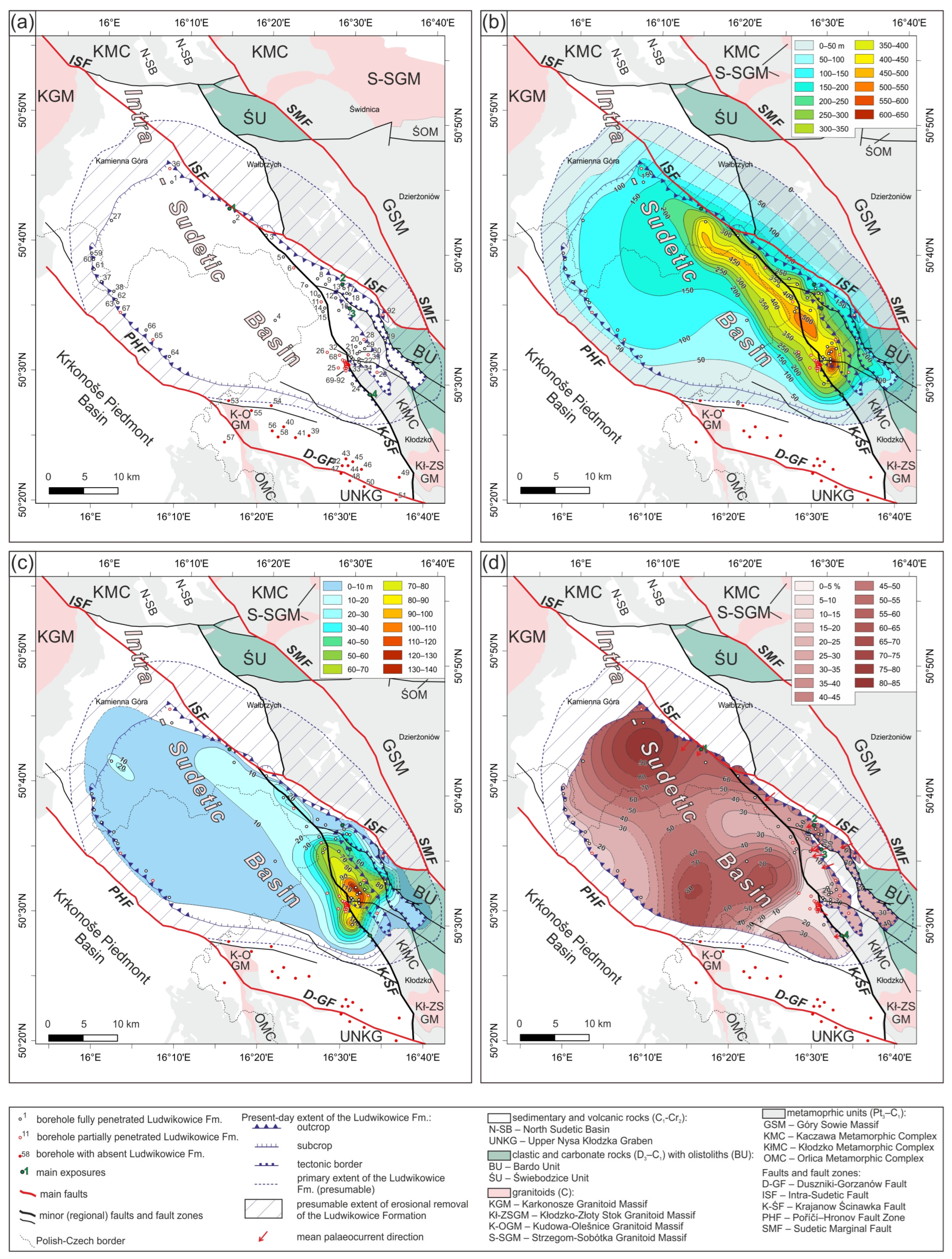
Figure 3. (a) Map showing the locations of boreholes (1–92) and representative exposures (1–4) analyzed in this study. (b) Bulk thickness map of the Ludwikowice Formation in the Intra-Sudetic Basin; note the present-day extent and the interpreted original extent of the formation. (c) Thickness map of the Lower Anthracosia Shale (uppermost Ludwikowice Formation). (d) Map showing the percentage (%) of coarse-grained lithofacies (conglomerates and coarse-grained sandstones) within the Ludwikowice Formation.
Minerals 15 01077 g003
Figure 4. Lithostratigraphic correlation along the WSW–ENE (C–C′) cross-section across the eastern part of the Intra-Sudetic Basin. For the location of the cross-section line see Figure 1. Pie charts show the percentages of coarse- to fine-grained facies and lacustrine deposits; note the gradual decrease in coarse-grained facies toward the basin depocenter–southwestward in the eastern sector and eastward in the central sector of the basin.
Minerals 15 01077 g004
Figure 5. Microscopic images of sandstones from the lowermost Ludwikowice Formation exposed in the eastern Intra-Sudetic Basin. (a,b) Poorly sorted arkosic/subarkosic to lithic arenites composed mainly of angular to subangular quartz (Q; some grains polycrystalline), feldspar (F), volcanic lithic fragments (Lv), muscovite (M) and biotite (B) grains, with a ferruginous matrix/cement. Note the low petrographic maturity of the sandstone. (cf) Poorly sorted arkosic/subarkosic to lithic arenites with calcite cement (C, Cc). Note the tabular, horizontal stratification in (e) (Sh), marked by red dotted lines.
Minerals 15 01077 g005
Figure 6. Exposure-scale geometry and lithofacies characteristics of the lowermost Ludwikowice Formation in the eastern Intra-Sudetic Basin, shown in exposure 1 (a) and exposure 3 (b,c). Lithofacies code as in Table 1. Erosional surfaces associated with fluvial channels are marked by white dashed lines. The lower parts of composite beds consist of gravel-dominated facies including Gcm (massive, clast-supported conglomerates) and Gcg (normally graded conglomerates), and subordinately of Gh and GSh, which commonly grade upward into cross-bedded units of Gp, GSp, Sp, SGp as well as Gt, GSt, St, SGt. The inset rose diagram in (b) shows paleocurrent data recorded in exposure 3: cross-bedding orientations with mean direction (red arrow) and channel axes (black arrows).
Minerals 15 01077 g006
Figure 7. Sedimentological log of the middle part of the Ludwikowice Formation in the Ścinawka Średnia PIG-1 (SC) borehole (80.0–200.5 m interval). Note the predominance of fine-grained lithofacies.
Minerals 15 01077 g007
Figure 8. Sedimentary features of the middle part of the Ludwikowice Formation from the Ścinawka Średnia PIG-1 (SC) borehole. (a) Brown massive mudstone (Mm) and bioturbated sandy mudstone (MSmb) with distinct carbonate nodules (arrowed). (b) Ripple-laminated sandstone (Src) interbedded with horizontally stratified sandstone (Sh), forming sandstone–mudstone couplets. (c) Alternation of sandstones and mudstones forming heterolithic units (S/Mhb). (d) Mmb lithofacies containing claystone (Cm) laminae up to 1 cm thick. (e) Horizontally stratified sandstone (Sh; marked with white dotted lines). (f) Deformed heterolithic interval with mudstone intraclasts within a sandy matrix. (g) Sets of ripple-laminated sandstones (Src) with loaded base. (h) Molds of raindrop imprints on the sole of a mudstone bed in overbank deposits (FA2). (i) Centimeter-scale pinstripe lamination (Sx). (j) Carbonate pseudomorphs after sulfates (arrowed) within massive mudstone of FA4.
Minerals 15 01077 g008
Figure 9. Sedimentary features of the uppermost part of the Ludwikowice Formation from the Rybnica Leśna PIG-1 (RL) borehole (FA5 and FA6 facies associations). (a) Greenish-grey heterolithic deposits (S/Mhg) with brown, siderite-rich lenses and concretions. (b) Coquina bed composed of Anthracosia sp. shells. (c) Heterolithic sandstone–mudstone couplets with ripple-laminated sandstone units (Src) and escape traces (arrowed). (d) Sharp-based shell lag composed of Anthracosia sp. fragments (Gco), forming convex-up and convex-down accumulations, interpreted as storm-lag deposits. (e) Bioturbated sandstones (Sb) and mudstones with root traces (arrowed).
Minerals 15 01077 g009
Figure 10. Sedimentary features of the uppermost part of the Ludwikowice Formation from the Rybnica Leśna PIG-1 (RL) and Ścinawka Średnia (SC) boreholes (facies associations FA7–FA9). (a) Sharp-based, coarse-grained grey sandstone (Sg) showing both inverse and normal grading and soft-sediment deformation (Sd), with dispersed plant detritus (arrowed). (b) Intervals of graded sandstone (Sg) passing upward into ripple-laminated sandstone (Src); the lower part of bed displays distinct load cast indicating rapid loading and subsequent dewatering. (c) Set of climbing ripple-laminated sandstone (Srcl). (d) Massive grey mudstone (Mm) with syndepositional fault-related folds (white dotted lines) and small-scale overthrust (yellow arrow). (e) Transitional interval between the open-lake facies association (FA9; 144–142.7 m in this view) and the prodelta facies association (FA8; 142.7–140.0 m in this view). (f,g) Sets of sandstone with climbing ripple cross-lamination (Srcl) and lenticular cross-lamination (Srle), interlayered within massive dark-grey mudstone (Mm; ’black shale’) of FA8. (h) Single shell of Anthracosia sp. within massive calcareous mudstone (black shale). (i). SEM image of the pyrite accumulation (marked as ‘p’) in the massive mudstone (FA9). (j). Microscopic image of the framboidal pyrite (arrowed) from massive mudstone (FA9).
Minerals 15 01077 g010
Figure 11. Photomicrographs of fine-grained lithofacies from the Rybnica Leśna PIG-1 (RL) and Ścinawka Średnia PIG-1 (SC) boreholes (crossed nicols, XPL, unless noted). (a) Poorly sorted, fine-grained calcareous sandstone (FA7) (XPL). (b) Poorly sorted, fine-grained sandstone with a grain framework composed of quartz, feldspar, muscovite, clay minerals, and pyrite (XPL). (c) Sandy mudstone with a thin calcareous (calcite) vein and very faint horizontal lamination. (d) Lenticular carbonate concretions within mudstone. (e) Calcareous mudstone with a cross-section of a mollusc shell, probably Anthracosia sp., and an OM lamina (XPL). (f) Mudstone with a ferruginous matrix and lenticular carbonate lenses forming faint horizontal lamination (XPL).
Minerals 15 01077 g011
Figure 12. Sedimentological log of the uppermost part of the Ścinawka Średnia PIG-1 (SC) borehole (10.0–80.0 m), with trendlines for carbonate content (%), magnetic susceptibility (MS), elemental ratios (Fe/Mn, C/P, (Na + Mg)/Al, Si/Al), and bulk carbonate isotopes (δ18O, δ13C) plotted alongside the profile. Explanations of lithological symbols as in Figure 7.
Minerals 15 01077 g012
Figure 13. Microscopic characteristics of a dolomite sample from the Ścinawka Średnia PIG-1 (SC) core. (a) Hand specimen photograph showing pervasive porosity in the dolomite. (b) SEM image of dolomite exhibiting intercrystalline porosity. (c) Photomicrograph showing a plant-tissue fragment embedded in the dolomite matrix. (d) Photomicrograph illustrating variation in dolomite crystal size.
Minerals 15 01077 g013
Figure 14. Sedimentological log of the uppermost part of the Rybnica Leśna PIG-1 borehole (95–167 m), with trendlines for carbonate content (%), magnetic susceptibility (MS), elemental ratios (Fe/Mn, C/P, (Na + Mg)/Al, Si/Al), and bulk carbonate isotopes (δ18O, δ13C) plotted alongside the profile. Explanations of lithological symbols as in Figure 7.
Minerals 15 01077 g014
Figure 15. Plot of the δ13C and δ18O carbonate isotopic values from tle RL and SC sections with marked covariance trend in SC calcite samples.
Minerals 15 01077 g015
Figure 16. Photomicrographs of typical dispersed organic matter in the Lower Anthracosia Shale under oil immersion; (ac) reflected white light, (df) incident fluorescence. (a) Vitrinite and inertinite fragments (humic association). (b) Humic association composed of inertinite and vitrinite fragments with small humic debris. (c) Vitrinite and inertodetrinite within a mineral matrix (humic association). (d) Telalginite and liptodetrinite showing yellow fluorescence in a bituminous–mineral matrix. (e) Brightly fluorescent lamalginite within bituminite. (f) Brightly fluorescent lamalginite and telalginite in a bituminous–mineral matrix. Abbreviations: V—vitrinite, In—inertinite, Id—inertodetrinite, Db—humic debris, Al—alginite, Lam—lamalginite, Te—telalginite, Ld—liptodetrinite, RL—Rybnica Leśna PIG-1, SC—Ścinawka Średnia PIG-1.
Minerals 15 01077 g016
Figure 17. Sedimentological log of the studied LAS interval from the Rybnica Leśna PIG-1 (RL) borehole plotted together with maceral composition (V–vitrinite; L–liptinite; BMM–bituminous–mineral matrix; SB–solid bitumen; I + Re–inertinite and reworked vitrinite), palynofacies composition (PHY–phytoclasts; AOM–amorphous organic matter; Sp–sporomorphs), composition of miospore assemblages, degree of miospore degradation/preservation (FG–fairly good; RP–rather poor; VP–very poor), and organic associations (MCAs). Ternary diagrams show the proportions in the system [vitrinite + sporinite]–[alginite + bituminite + liptodetrinite + bituminous–mineral matrix]–[inertinite + reworked vitrinite]. Explanations of lithological symbols as in Figure 7.
Minerals 15 01077 g017
Figure 18. Sedimentological log of the studied LAS interval from the Ścinawka Średnia PIG-1 (SC) borehole plotted together with maceral composition (V–vitrinite; L–liptinite; BMM–bituminous–mineral matrix; SB–solid bitumen; I + Re–inertinite and reworked vitrinite), palynofacies composition (PHY–phytoclasts; AOM–amorphous organic matter; Sp–sporomorphs), composition of miospore assemblages, degree of miospore degradation/preservation (FG–fairly good; RP–rather poor; VP–very poor), and organic associations (MCAs). Explanations of lithological symbols as in Figure 7.
Minerals 15 01077 g018
Figure 19. Representative photomicrographs of palynofacies from the Rybnica Leśna PIG-1 (RL) and Ścinawka Średnia PIG-1 (SC) boreholes: (a) assemblage composed almost exclusively of AOM (bituminous association), RL, 143.9 m; (b) AOM-rich palynofacies with numerous phytoclasts (intermediate association), SC, 43.6 m; (c) palynofacies with abundant AOM and numerous phytoclasts (intermediate association), RL, 142.85 m; (d) palynofacies dominated by phytoclasts (humic association), RL, 113.2 m.
Minerals 15 01077 g019
Figure 20. Paleogeographic reconstruction for the latest Carboniferous (late Gzhelian), depicting the depositional setting of the Ludwikowice Formation and illustrating four evolutionary phases (ad) of the Intra-Sudetic Basin during this interval. For letter-symbol explanations, see Figure 1. Note the possible connection between the ISB and the Krkonoše Piedmont Basin.
Minerals 15 01077 g020
Table 1. Summary and interpretation of lithofacies distinguished within the Ludwikowice Formation.
LithofaciesDescriptionOther Sedimentary FeaturesInterpretationFacies Associations
Gcm
Gh
GSh
Clast-supported conglomerates ranging from structureless, massive (Gcm) to crudely horizontally bedded conglomerates (Gh) and sandy conglomerates (GSh); bed thickness from one clast to <0.4 mImbrication and pebble lineation in lower bed parts (a (t) b (i) fabric); concave-up erosional bases (Gcm); crude horizontal bedding and scattered brownish mudstone/sandstone intraclasts (Gh/GSh)Deposits of basal, aggradational parts of fluvial channels and channel-floor lags; formed under strong, erosive flows with sediment bypass; diffuse gravel sheets and small-scale longitudinal gravel bedforms.FA1
GcgClast-supported conglomerates with normal grading; bed thickness < 0.3 mNormal grain-size grading; sharp and erosional lower contact of bedsChannel or bar deposits formed by rapid flow deceleration. Lower parts of gravel bedforms.FA1
GmmMatrix-supported, massive (structureless) conglomerates; beds 0.05 to 0.3 m thick; clasts embedded in a medium- to coarse-grained sandstone matrixStructureless; non-erosional, sharp bed boundariesDeposits of high-strength debris flows, formed under support from pore fluid pressure, and/or dispersive pressure. Gravity flow sheets and lobes in alluvial channels (FA1) or high-density turbidity current/grain flow deposits on subaqueous delta slopes within lacustrine setting (FA7).FA1
FA7
GmgMatrix-supported, normally to inversely graded conglomeratesNon-erosional bases, lack of internal structureDeposits of waning cohesive debris flows or transitional flows; formed as lobes in alluvial abandoned channels and overbank (FA1) or as high-density turbidity current/grain flow deposits on subaqueous delta slopes within lacustrine setting (FA7).FA1
FA7
GcoCoquina beds; thickness < 5 cmContinuous lags or clusters of shell debris (observed at core scale); sharp, undulating erosional surfaces; accumulations of Anthracosia sp. coquinasStorm-generated lags developed under strong erosion and winnowing of sand-sized particles.FA5
Gp
GSp
Sp
SGp
Conglomerates and sandstones (clast- to matrix-supported); sandstones with scattered granule to pebble-sized clasts and intraclasts (SGp)Planar (tabular) cross-bedding; inclined graded foresets with reactivation surfaces; pseudo-imbricated pebbles and mudstone/sandstone intraclasts up to 4 cm; bounded by sharp planar erosion surfacesDeposits of straight-crested, 2D gravelly and sandy dunes formed under lower- to middle-flow regime conditions; mid-channel transverse or linguoid bars, or unit bars accreted under unidirectional subaqueous currents.FA1
Gt
GSt
St
SGt
Clast- to matrix-supported conglomerates (Gt, GSt) and medium- to coarse-grained sandstones with dispersed granule to pebble-sized clasts (St, SGt)Trough cross-bedding; lenticular beds 0.2–0.5 m thick with concave-up erosional bases and gradational tops; imbricated clasts in lower parts; pseudo-imbricated pebbles and reactivation surfaces in sandy faciesDeposits of sinuous-crested, 3D gravelly and sandy dunes migrated as mid-channel transverse, linguoid bedforms. Formed under upper limits of the lower flow regime by unidirectional subaqueous currents; typical for braided river environments.FA1
Sh
Sl
SGh
SGl
Medium- to very coarse-grained sandstones with scattered sub- to well-rounded granule to cobble-sized clastsLow-angle planar cross-stratified bed sets a few meters wide and up to 1 m thick; foreset dips 3–15° (Sl, SGl), usually <10°; tabular horizontal stratification up to 0.2 m thick (Sh, SGh); laterally extensive with flat or irregular, non-erosional boundariesDeposits of plane-bed transport under upper flow regime conditions during flash floods or rapid flow pulses; washed-out dunes and/or antidunes (Sl, SGl), and sheet-like sandy bedforms (Sh, SGh) (FA1, FA2). In lacustrine setting formed by winnowing and/or high-rate sediment fallout from bedload traction currents or surging HDTC (high-density turbidity currents) (FA7).FA1
FA2
FA7
SxMedium- to coarse-grained, very well-sorted sandstone; quartz-rich; pale yellow to reddish; single granulesPinstripe lamination: closely spaced, sub-millimeter planar laminations; horizontal to gently inclined; visible over centimeter to decimeter scale in core; locally diffuse or rhythmicAeolian wind-ripple strata or sands sheets deposited in interdune flats (?) or on dune flanks; formed under low-energy, unidirectional wind conditions. FA4
SgFine- to coarse-grained graded sandstone; sporadic granules and scattered small clasts presentNormal or inverse grading; beds with sharp basal contacts; typically massive or faintly stratifiedDeposits of sandy debris flows or high-density turbidity currents on delta slopes or subaqueous fans (FA7); reflect en masse sediment freezing or rapid deposition from turbulent suspension.FA7
FA8
SdFine- to coarse-grained sandstone; poorly sorted; originated probably from graded sandstones (Sg)Deformed bedding; load casts, flame structures, convolute lamination, slumps; internal disruption of primary stratification; may occur as discrete zones or entire bedsSoft-sediment deformation of Sg and Sm due to rapid loading, water escape, or slope instability. Formed shortly after deposition due to liquefaction and/or gravitational collapse. Often associated with high sedimentation rates and/or seismic triggers (?).FA7
SmMedium- to coarse-grained sandstone with scattered sub-rounded and well-rounded granule to pebble-size clastsMedium- to large-scale lenticular geometry; lateral extent up to 2 m and thickness 0.2–0.4 m; lacks internal structureDeposits formed by sudden discharge of sediment-laden flow; interpreted as rapid fallout from traction carpet or collapse of subaqueous sandy bedforms; indicative for upper-flow regime conditions (FA1).FA1
FA7
SbFine- to medium-grained sandstone; well to poorly sortedStrong bioturbation—root-related or due to infaunal burrowing; original sedimentary structures commonly obliterated or strongly overprintedDeposits of low-energy environments with prolonged or repeated exposure to colonization by plants and invertebrates; commonly associated with floodplains, levees, or shallow lacustrine margins subject to intermittent inundation and subaerial exposure.FA2
FA4
FA5
FA6
SrcVery fine- to medium-grained, well-sorted sandstoneAsymmetrical ripple cross-lamination with undulatory or linguoid ripple forms; cross-laminated sets 2–6 cm thick; laminae often accentuated by silt drapes; load casts occasionally present at basesDeposits of subaqueous ripple migration under low-velocity (<1 m/s), unidirectional flows; formed in the lowermost part of the lower flow regime. Common in a wide range of depositional settings across fluvial and muddy floodplain environments (FA1, FA2); also in transitional to lacustrine environments (FA5–FA9).FA1
FA2
FA5–FA9
SrclFine- to medium-grained, well-sorted sandstoneClimbing ripple cross-lamination; typically low-angle with upward migration of ripple crestsDeposits formed by rapid fallout from sediment-laden flows with high suspended load; indicative of low-velocity, unidirectional current and high sedimentation rate; commonly associated with flood-related waning flows (FA2) and high-density turbidity currents on delta slopes or subaqueous fans (FA7) in lacustrine setting.FA2
FA7
SrleFine- to medium-grained, well-sorted sandstone or silty sandstoneFlaser to lenticular bedding; sets are laterally discontinuous, pinch-and-swell geometry; commonly irregular laminae thicknessDeposits formed under low-energy, variable-flow conditions; likely associated with alternating weak currents and slack water phases. Typical of periodically inundated muddy floodplain (FA2), lacustrine nearshore (FA5), and distal prodelta settings (FA8).FA2
FA5
FA8
S/MhbBrown to reddish interbedded fine-grained sandstone and mudstone (heterolithics); sharp or gradational contacts; often mottled or variegated in colorStrong bioturbation; pedogenic features: root traces, slickensides, carbonate nodules and nearly continuous horizons, mottling, or faint lamination; may include weak paleosol horizons. Shrinkage cracks and raindrop imprintsDeposits of intermittently flooded floodplain or abandoned channel fills subject to periods of exposure; modified by soil formation and biological activity; indicative of low-energy, subaerially influenced fluvial environments.FA2
S/MhgGreen to grey interbedded fine-grained sandstone and mudstone (heterolithics); well-sorted; typically micaceousLaminated and heterolithic deposits, ripple cross-lamination; bioturbation and escape structures; bedding contacts sharp to gradationalSubaqueous nearshore lacustrine deposits (FA5); reflect alternating fine sand and mud sedimentation in shallow water below and above wave base.FA5
SMdDeformed interbedded mudstones and very fine- to fine-grained sandstones; reddish to brownish in colorSlump folds, flame structures, dish-and-pillar features, convolute lamination; loss of primary bedding; sharp or irregular internal boundaries; occurs as isolated deformation zones within floodplain deposits.Soft-sediment deformation of heterolithic floodplain deposits triggered by rapid sediment loading, fluid overpressure, or seismic activity. Represents in situ liquefaction or slump features formed shortly after deposition during early compaction or minor syndepositional disturbance.FA2
Mm
Mmb
MSmb
Dark brown to reddish-brown massive (Mm) and bioturbated mudstones (Mmb) with sporadic intercalations of very fine- to fine grained, red-pinkish sandstone (MSm)Massive structure or weak horizontal lamination in sandy mudstones; discontinuous lenses and sheets; strong bioturbation and pedogenic features (root traces, slickensides, carbonate nodules, mottling)Deposits formed by suspension fallout in floodplain depressions, ephemeral ponds, or abandoned channels, followed by drying, bioturbation (infaunal and root-related), and pedogenesis. Indicative of low-energy floodplain environments (FA2) affected by alternating aquatic deposition and subaerial modification.FA2
Mm (c)
Mh (c)
Grey calcareous mudstones; massive (Mm) or slightly heterolithic; carbonate-richStructureless to faint horizontal lamination; interbedded with thin silty or fine sandy layers in heterolithic varieties; may show weak bioturbation or burrow mottlingDeposits formed under low-energy, suspension-dominated conditions with carbonate input; typical of shallow lacustrine settings influenced by both clastic and carbonate sedimentation.FA8
Mm (g)Grey mudstones; massive or slightly heterolithic, predominantly non-calcareousStructureless to faintly laminated; locally bioturbated with root traces, mottling, and dispersed plant detritus Deposits formed by suspension fallout in low-energy, distal overbank or delta plain environments situated between distributary channels. Periodic subaerial exposure promoted root bioturbation and minor soil formation; the presence of organic matter reflects intermittent vegetation cover and waterlogged conditions.FA6
FA8
FA9
MCmDark grey to black, fissile, clayey mudstones; rich in organic matter; commonly slightly laminated.horizontal lamination or fissility; absence of bioturbation; occasional plant debris; may contain pyrite framboids or other diagenetic mineralsDeposits formed under low-energy, anoxic to dysoxic conditions in stagnant water bodies with high organic productivity and minimal bottom current activity.FA8
FA9
CmBrown claystones; a few cm thickMassive structure or faint horizontal lamination; occasional mottling; enriched in calcium carbonate, either dispersed or as incipient mm-scale nodulesSuspension fallout deposits resulted from waning overbank floodwaters, followed by periods of subaerial exposure and incipient pedogenesis.FA2
FA4
Disclaimer/Publisher’s Note: The statements, opinions and data contained in all publications are solely those of the individual author(s) and contributor(s) and not of MDPI and/or the editor(s). MDPI and/or the editor(s) disclaim responsibility for any injury to people or property resulting from any ideas, methods, instructions or products referred to in the content.