Abstract
In this study, the effects of batch and continuous grinding on the ceramic floor tile body were investigated in terms of cost, capacity, and technical aspects. In batch milling, a changing speed during grinding was more efficient than a constant speed. Capacity and energy consumption increased as the mill rotation speed increased in continuous grinding. Specific energy consumptions were measured as 36 kW/ton and 43.1 kW/ton, with 1.6 ton/h and 8.375 t/h capacities. Additionally, d10, d50, and d90 values for ground ceramic floor tile bodies were determined to be 2.5, 9.5, and 47.2 µm and 2.5, 9.4, and 48.1 µm for batch and continuous grinding, respectively. No significant difference was observed in the color and shrinkage values, while water absorptions were calculated to be 1.1% and 0.3% as sintering properties for batch and continuous methods, respectively. In the phase analysis of a sintered body prepared using the continuous method, mullite and quartz were observed, while microcline was also analyzed differently from such minerals for the batch one. Structural changes, surface morphology, and roughness were also interpreted by DTA/TG, SEM, and AFM analysis. The presence of plastic clay minerals during the grinding process in batch milling caused non-plastic raw materials not to be ground sufficiently, and sintering characteristics changed.
1. Introduction
Today, since pure ore resources are being depleted, it is not possible to use raw materials extracted from the earth’s crust as in the relevant industry. For this reason, raw materials are subjected to mineral processing and enrichment processes to beneficiate valuable mineral content. If such minerals are used in their pure form, unique properties are supplied by the materials. On the other hand, many minerals are used in ceramics, cement, etc., due to their various properties, and they are transformed into different materials through various processes in industrial branches. At this stage, the particle size of minerals affects both final the properties of materials and production parameters of process [1].
Ceramic tile production consists of raw material preparation processes such as particle size reduction, classification, and granule formation, as well as pressing, drying, glazing, and firing processes [2]. In the preparation of ceramic raw materials, particle size reduction is carried out by crushing and grinding. While jaw, impact, and cone crushers are used in the crushing process, the grinding process is generally performed by wet ball mills [3]. Ceramic body compositions comprise plastic and non-plastic hard raw materials. Here, clay group plastic raw materials are blunged with mixers, and hard raw materials are ground with ball mills to reduce the desired particle sizes in the ceramic industry by using low energy [4,5]. Primarily, particle size distribution obtained in the grinding process regulates the properties of the granules produced, the reaction rate of the particles, and the phases formed in the sintering step [6]. Therefore, the technical properties of the final product are affected, such as water absorption, size, and deformation after sintering. For this reason, the particle size distribution is one of the important parameters affecting tile production quality [7]. Although dry or semi-wet systems are being tried to reduce the cost of water evaporation, a more homogeneous product is obtained in wet grinding than in dry grinding [8]. Therefore, the granules produced with the proper particle size distribution and subsequent spray drying have better flow and packing-granule properties. Since granules fill the mold well, better pressing is provided during the shaping process. For these reasons, wet grinding systems are widely used in ceramic tile production today [9].
Nowadays, ceramic manufacturers prefer to work with dry grinding and granulation systems due to water evaporation costs. Therefore, researchers are working on issues related to the production of ceramic body compositions in a dry environment. Dry environment fine grinding technologies such as stirred media mills and ML-assisted grinding models can be successfully applied in the production of ultra-fine raw materials in terms of the current technology [10,11]. However, since the homogenization of the minerals that constitute the ceramic body cannot be achieved with the existing dry granulation methods, manufacturers design body preparation systems to operate in a wet environment. For these reasons, ball mills, which perform particle size reduction in a wet environment, are preferred for grinding raw material compositions. Ball mills produce finer products with a length-to-diameter ratio typically ranging from 1 to 1.5. To produce fine-sized particles, the mill length is increased to achieve a 3 to 5 length-to-diameter ratio, and the system is described as a tube mill having compartments divided to suit different feed types [12]. Ball mills can have cylindrical, cylindrical–conical, or conical body designs. In conical design mills, the inlet section is cylindrical and the outlet section is conical [13]. Thanks to this design, large balls and coarse particles are concentrated at the inlet, while small balls and fine materials move towards the outlet. The grinding process takes place when the balls come into contact with the ore particles, and, with sufficient time, a product finer than 50 µm can be obtained [14]. However, in open-circuit systems, the product may have a wide particle size distribution. To prevent this situation, closed-circuit systems are preferred. Thus, fine particles are removed from the environment and coarse particles are allowed to continue the grinding process [15].
Wet continuous and batch ball mills are used in ceramic tile production. The effectiveness of ball mills is evaluated by the product obtained per unit of time and the energy consumed [16]. Design and operating parameters such as mill diameter/length, type of mill liner, shape/size distribution/specific gravity of the grinding medium, grinding medium/feed material ratio, mill rotation speed, etc., significantly affect the grinding efficiency in terms of technical and economic aspects [17]. As the mill diameter and ball size increase, the impact force and intensity become more effective, while the number of collisions between the grinding medium and the ground material decreases [18]. This creates an efficient condition for the grinding of coarse grains. However, to produce fine-sized material, the abrasion force should be made effective by using small-sized balls in a long mill with smaller diameters [19]. A grinding medium with a high specific gravity and hardness also enhances the grinding efficiency due to the impact and frictional force increment [20]. The efficiency of grinding also depends on the filling rate of the mill. The filling rate is defined by the volume occupied by the grinding environment and raw material. In total, 35%–50% of the usable volume is filled by the grinding medium and raw material depending on the specific weight in the ceramic grinding process [21].
Continuous mills have a cylindrical shape like batch mills but have longer axial lengths than batch mills. Continuous mills generally contain special chambers with openings that allow the ground slurries to pass but do not allow the balls to pass, and they have a certain slope to transfer the ground materials. The first chamber, near the inlet, contains large balls for grinding coarse-sized particles by using impact force. The following chambers consist of smaller balls to grind fine-sized materials by using frictional force more [22]. On the other hand, horizontal/vertical attrition ball mills, where the abrasive force is used efficiently by mixing the grinding medium and material with a mixer for dry grinding, are also studied in terms of batch and continuous grinding methods in the literature [23,24].
In the grinding of ceramic bodies, the operating method and equipment-related parameters include capacity, the internal structure and the types of liners (metal, rubber, stone, porcelain), rotational speed, grinding medium (silica or aluminum), raw material, and water amount [25,26]. Parameters such as the suspension density, viscosity, thixotropy, temperature, dispersant dosage/type, raw material composition, and water quality are related to the raw material and recipe composition [27]. Batch mills consume significantly more energy than continuous mills. Increasing the solid content of the slurry provides an opportunity for energy efficiency in spray drying process after wet grinding operation [28]. The modular design of the mill allows continuous or batch operations, different configurations according to the production plan, and potential electricity savings. The grinding media and mill lining are important for decreasing grinding time and saving energy. Most batch mills use a soft-start motor or a second motor to start operation, using the main motor for rotation once grinding has begun. Variable mill speeds throughout the grinding process significantly affect grinding efficiency. Increasing the suspension temperature also facilitates the grinding process [29,30].
Grinding remains the most energy-intensive stage in the mineral preparation processes, accounting for more than half of the total energy used in this area. Therefore, facilities need to be improved, equipped with the right machinery, and energy-saving methods need to be implemented. Additionally, choosing a mill that is not suitable for the characteristics of the ore will undoubtedly increase the operating costs. In this study, technical performance analyzes of a batch horizontal shaft mill and a modular continuous mill (two-chamber version) currently used in the ceramics industry were made and evaluated by means of energy efficiency, capacity utilization rate, and product characteristics in a wet medium. The capacity and specific energy consumption values were compared at different mill revolution speeds. Batch/continuous-ground samples were compared in terms of particle size distribution, chemical composition, and sintering properties by using XRF, XRD, DTA-TG, SEM-EDS, and AFM methods in floor tile sintering conditions. Two different kinds of technology and grinding methods were compared in terms of capacity, electric consumption, grinding characteristics, and the effect on the ceramic composition. The novelty of this study is to examine the significant differences obtained in terms of technical, economic, and capacity aspects in industrial terms, as well as the possible environmental effects when using the continuous ball milling method for grinding ceramic body compositions in a wet environment compared to batch grinding.
2. Materials and Methods
2.1. Materials
Clay and altered granite, kaolin, and feldspar samples were obtained from Istanbul and Yozgat regions in Türkiye, respectively. Firstly, the chemical contents of raw materials were analyzed with the Axios Max model X-ray Spectrophotometer (XRF, Panalytical, Almelo, Netherlands) and the phase analyzes with X’pert Pro MPD X-ray Diffractometer (XRD, Panalytical, Almelo, Netherlands). XRD scan parameters were as follows: a start–end angle: 2.998°−70.000° 2θ, step size: 0.0167° 2θ, time per step: 40.00 s, scan speed 0.053052°/s. High score evaluation program, COD, and PDF-2 databases were used to determine XRD diagrams. The results of the chemical (XRF) and mineralogical (XRD) characterization for the raw materials are presented in Table 1. The XRD patterns of raw materials were also given in Appendix A.

Table 1.
Chemical and mineralogical properties of raw materials.
2.2. Methods
Raw materials were prepared through wet grinding in a laboratory ball mill to determine slurry characteristics. For the slurry, 0.45% of Merck extra pure sodium silicate (SS), Germany, and 0.16% of Tekkim extra pure sodium tripolyphosphate (STTP), Türkiye, were used as dispersants at a 1700 g/L slurry density. The ratio of dispersant dosages was determined by dividing the dry weight of material by the weight of dispersant.
The density values of the slurry were measured with a pycnometer, and the flow time was analyzed with a Ford cup (4 mm nozzle diameter and 200 mL volume). In order to determine and compare grinding times, the raw materials were ground until they reached 6% sieve residue at +63 µm. The Bond Work Index was also used to determine the grinding properties of hard raw materials such as kaolin, altered granite, and feldspar. Clay was not subjected to Bond Work Index experiments due to the plastic form. Crushed raw materials of −3.36 mm were used with a 30.5 cm diameter/30.5 cm long stainless-steel standard Bond mill in the experimental study. The mill was loaded with 22.648 kg of stainless-steel balls with diameters of 38.1, 31.75, 25.40, 19.05, and 12.70 mm corresponding to 22% of the clearance volume, and operated at 70 rpm, 86% of the critical speed. In each experiment, 100% of the ball cavity volume (700 cm3) was filled with −3.36 mm size feedstock; a test sieve with a 75 µm aperture was used in Bond Work Index experiments. The experiments were performed according to standard Bond Work Index determination [31]. The results of the physical analysis of the raw materials are shown in Table 2.
Table 2.
Physical properties of raw materials.
The raw materials were fed to the mills with particle sizes of −5 mm for altered granite, kaolin, and feldspar, and −10 cm for the clay group. The raw materials used in the grinding experiments to produce the floor tile ceramic body are given in Table 3 by weight.
Table 3.
Floor tile ceramic body recipe used in the grinding experiments.
In this study, dispersant dosage, slurry density, ball load, and ceramic body recipe were applied based on the parameters used in laboratory and industrial working conditions for sieve residue. In batch grinding, 13,000 kg of raw materials was loaded into the batch mill with municipal water and dispersants (0.7% SS and 0.07% STPP). Then, the materials were ground to reach 6% residue for 63 µm in a closed circuit, and a specific energy/capacity calculation was made accordingly. In continuous grinding, 8375 kg/h of raw materials was fed into the mill with municipal water and dispersants (0.7% SS and 0.07% STPP) continuously. The residue values were calculated for 63 µm sieve aperture, and specific energy consumptions were measured according to 9, 10, 11, 12, and 13 rpm of mill speeds in continuous grinding. The 1690 g/L slurry density was used for both industrial grinding experiments, and water additions were measured accordingly. The alumina ball with the 3.57 g/cm3 specific weight was used as grinding media, and size distributions for batch and continuous grinding were chosen as the industrial working conditions, as shown in Table 4.
Table 4.
Ball loads for batch and continuous mills.
In continuous grinding experiments, a two-chamber ball mill, which had a 2920 mm diameter, 10,500 mm length, and rubber liners, was used. The transmission change was achieved by an orthogonal-axis reducer and V-belts that directly rotated the cylinder. This mill had 2 × 250 kW asynchronous 3-phase motors with a hydraulic coupling for soft, gradual start-ups, and auxiliary motors (2 × 18.5 kW) for slow rotation and mill positioning. The mill was fed by a screw with a stainless-steel pipe, lined entirely with polyurethane. Both chambers had 5 cm thick rubber lining.
A ball mill with a 110 kW motor was used in batch grinding, which had a 3100 mm diameter, 4600 mm length, and 10 cm thick alumina liners. An inverter was used for adjusting different mill speeds, and a three-phase power logger was used to determine energy consumption in the grinding step for both ball mills. The real images of the continuous and batch mills used in industrial grinding studies are given in Figure 1a,b, respectively.
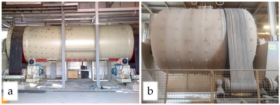
Figure 1.
The real images of continuous (a) and batch (b) mills.
The mill rotational speeds of the mills were evaluated proportionally to the critical speed, as seen in Equation (1).
where Nc is the critical speed (rpm), D is the mill inlet diameter (cm), and d is the maximum ball diameter (cm).
The critical speeds were calculated as 24.9 and 25.4 rpm for batch and continuous mills, respectively.
In the preparation of ceramic bodies, raw materials were first taken from silos according to the ratios of the ceramic recipe, weighed with automatic weighing belts, and subjected to the grinding process in an aqueous medium with dispersants. In batch grinding, the raw materials were added to the mills with water and dispersant according to the ceramic recipe, the mill cover was closed, and grinding started in an aqueous medium with dispersants. After the grinding process, the mill cover was opened, and the ground material was discharged. In the continuous grinding, the raw materials were weighed with automatic weighing belts, water/dispersant was continuously fed to the mill through flow meters, and measurements were performed as the grinding process became stable in terms of sieve residue/capacity. The flowsheet of the grinding study is shown in Figure 2.
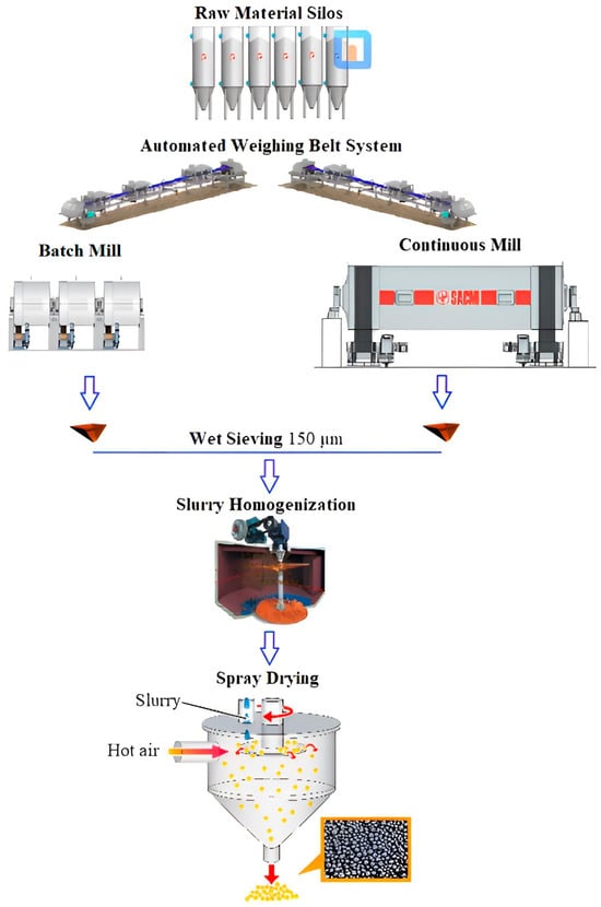
Figure 2.
Industrial-based ceramic granule preparation flowsheet with wet batch and continuous grinding system.
The Malvern Mastersizer Micro Plus device was used to determine the particle size distribution of the batch- and continuous-ground ceramic slurries, with a measurement range of 0.03 to 555 µm for the laser scattering method.
The slurries prepared with continuous and batch grinding were dried in a spray dryer to have 6% humidified moldable granules. The granules were then shaped in a laboratory-based pressing machine, sintered in an industrial kiln in porcelain sintering conditions, and evaluated in terms of ceramic characteristics.
A Setaram brand Labsys Evo model DTA/TG device was used to determine the thermal properties of the ground samples by heating with a rate of 10 °C/min to a maximum temperature of 1200 °C.
Water absorption measurement was realized in a compression tank at 10 ± 1 kPa of pressure and 30 min according to EN-ISO 10545-3 standard [32].
The firing shrinkage value (%) of samples was measured via the caliper with a precision of 0.01 and calculated with Equation (2), using the length of the dried sample (L1) and the length of the sintered sample (L2):
Color values (L, a, b) of sintered samples were determined by scanning the surface with a PCE XXM 30 color measuring device, which had a 400–700 nm wavelength range, and three analyses were applied for each specimen, with a 0.08 average color measurement accuracy (ΔE).
A Scanning Electron Microscope (SEM) of the Tescan brand Vega model was used for detailed imaging and elemental composition analysis of the sintered sample surfaces obtained by batch and continuous grinding methods. In order to increase the conductivity properties of the samples, the carbon plating process was performed by first applying a vacuum of 8.10−1 mbar/Pa and applying a current intensity of 10 mA. SEM images were taken from sintered specimens and HF (Hydrofluoric Acid)-treated sintered specimens. HF-treated samples were prepared in 3% HF solution by stirring them in a magnetic stirrer at 500 rpm for 1 min to dissolve the glass phase.
WITEC ALPHA 300RA model Atomic Force Microscope (AFM) was used to analyze the surface roughness of sintered ceramic body surfaces prepared using continuous/batch grinding methods. AFM measurements were performed in noncontact mode, 100 µm × 100 µm scan size, using a 20× objective. The roughness values were given as the arithmetic mean of the absolute values of the surface height deviations from the mean line, within a specified evaluation length (Sa), and as the root mean square average of profile height variation from the mean line (Sq).
3. Results and Discussion
3.1. Batch Ball Milling Studies
3.1.1. Effect of Permanent Mill Rotational Speed
To examine the permanent rotating speed, the mill was first fed with raw materials, water, and dispersants, and then the grinding process was started. Periodically, the ground samples were taken and analyzed to see the difference in sieve residue, and electrical consumptions were measured when the residues reached 6% for 63 µm (Figure 3).

Figure 3.
Sieve residues for +63 µm according to grinding time with permanent mill speed.
In rotary mills, the grinding process takes place mainly through high-intensity impacts generated by grinding media and feed material moving together with the rotating shell. When raised sufficiently, the media and particles are projected across the chamber and fall down due to gravity, striking other particles or the mill liner in the foot area. These dynamic collisions facilitate fracture, especially in large fragments, and represent the dominant breakage mechanism. Common types of interactions include media–media, media–ore, media–lining, ore–ore, and ore–lining contacts. Media tested included steel, rock, and glass, while wall materials consisted of steel, rock, and rubber [33]. The grinding time to reach 6% residue for +63 µm and energy consumption decreased from 540 min to 501 min and from 535 kW to 486 kW with the mill-rotating speed increment from 12 rpm to 16 rpm, which corresponded with values from 48.1% to 64.2% in terms of the critical speed ratio, respectively. From the viewpoint of mill-rotating studies, the particle size decreased rapidly until the 300th min at high speed (16 rpm), then slowed down and reached 6% of sieve residue for +63 µm. Therefore, the balls clung to the mill surface as much as possible and then fell with the combined effects of centrifugal and gravitational forces, resulting in a cataracting effect where the impact force was effective [34]. At a slow mill speed, the balls slid on each other and raw materials, causing a cascading effect where the friction force, rather than the impact force, was high [35]. Finally, the effect of the mill-rotating speed on the specific energy consumption and grinding capacity was calculated by changing the mill-rotating speed from 12 to 16 rpm as shown in Figure 4.
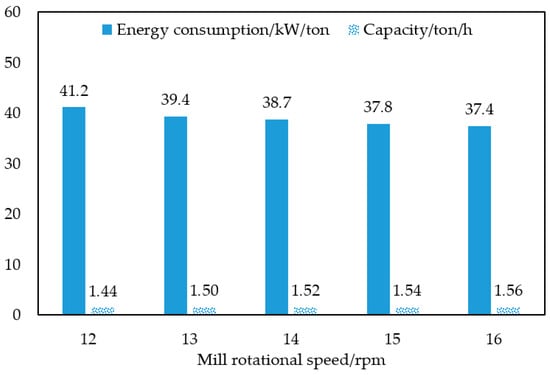
Figure 4.
The effect of permanent mill rotational speed on energy consumption and capacity for batch grinding.
The specific energy consumption decreased from 41.2 to 37.4 kW/ton, and ground material capacity increased from 1.44 to 1.56 ton/h with mill-rotating speed increments from 12 to 16 rpm, respectively. Experiments showed that increasing the speed also increased the power consumption, but the particle size did not change with power consumption. As the speed increased, the product size decreased to an optimum level (13 rpm). Beyond this level, the product could not be ground sufficiently.
3.1.2. Effect of Varying Mill Rotational Speed
The grinding experiments were carried out by dividing the whole grinding duration into three periods in order to understand the effects of varying mill rotational speeds on energy consumption and capacity. In each grinding experiment, the mill rotational speed started at 16 rpm in the initial 1st period, continued at 14 rpm in the 2nd middling period, and finished at 12 rpm in the 3rd final period. The grinding durations for each period were given as % for the whole grinding time. The batch grinding regimes are shown according to the mill rotational speeds and the grinding times applied in Table 5.
Table 5.
Regimes applied for batch grinding as varying rotational mill speed.
The speed variation in the first, middle, and last grinding periods was applied as varying grinding regimes: 515, 495, and 485 min of total grinding times with 501, 482, and 473 kW of total energy consumption measured for the 1st, 2nd, and 3rd regimes to reach 6% residue for a 63 µm sieve aperture, respectively (Table 5). Additionally, the specific energy consumptions and capacities calculated for the 1st, 2nd, and 3rd regimes in batch grinding are shown in Figure 5.
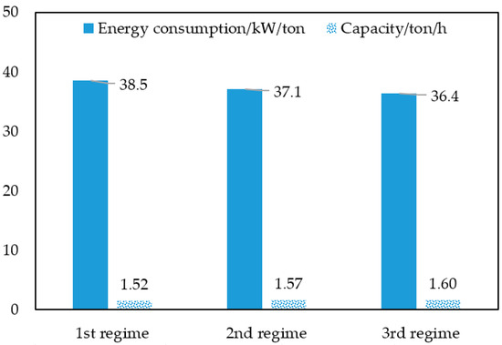
Figure 5.
The effect of varying mill rotational speed regime on energy consumption and capacity for batch grinding.
As the 1st, 2nd, and 3rd regimes were considered, the specific energy consumptions decreased to 38.5, 37.1, and 36.4 kW/ton, and the ground material capacity was increased to 1.52, 1.57, and 1.60 ton/h, accordingly. For the application of impact force on raw materials, coarse-grained raw materials were fed and crumbled by raising grinding media to a certain level inside the mill wall and tumbling freely on the coarse grains in the first period, with a high rotational speed [16]. After a while, the grains reaching a certain fineness were stuck between the grinding media and were not affected by the impact force, and the grinding efficiency decreased as seen in the permanent rotational speed given in Figure 3 [36]. For this reason, a friction force was required for the further size reduction of the grains that reached a certain fineness and were stuck between the grinding media. This process was carried out at low mill speeds, where the grinding media rolled over each other and fine-grained raw materials [37]. As seen in Table 5 and Figure 5, keeping the high-speed and low-speed processes, where the impact force and friction force were, respectively, effective, provided an increase in capacity and a decrease in specific energy consumption. As seen in Figure 3 and Figure 4, the particle size decreased rapidly at high mill speeds initially, but after a certain period the rate of particle size reduction slowed down. Therefore, it was understood that different mill speeds would be applied throughout the grinding process. Figure 5 clearly showed that a higher capacity could be achieved with lower specific energy consumption by applying first a high speed and then a low speed throughout the entire grinding process in the batch mill.
3.2. Continuous Ball Milling Studies
In continuous grinding studies, energy consumption and residues for a +63 µm sieve aperture were measured at different mill rotational speeds of 9, 10, 11, 12, and 13 rpm by keeping the feed amount of raw material at 8375 kg/h and the water (slurry density at 1690 g/L) and dispersant (0.7% SS and 0.07% STPP) dosages at constant values (Figure 6).

Figure 6.
The effect of different mill rotational speeds on energy consumption and sieve residues for continuous grinding.
As seen in Figure 6, the sieve residue for +63 µm decreased from 7.9% to 6.0%, and energy consumption increased from 27.9 to 43.1 kW/ton as the mill speed increased from 9 rpm to 13 rpm. In continuous milling, plastic clay minerals dispersed to a fine size more quickly, due to the effect of coarse-size balls, and quickly passed to the second chamber. Thus, non-plastic materials such as feldspar and quartz minerals, which contacted more with the balls and were ground effectively in the continuous mills, resulted in a fast residue decrement.
3.3. Particle Size Distribution of Batch/Continuous Grinding and the Effects on Sintering Properties
The optimum condition for the batch mill was obtained as 100, 200, and 185 min grinding duration in the 1st, 2nd, and 3rd periods at 16, 14, and 12 rpm regimes, respectively. The optimum condition for the continuous mill was achieved at a constant mill speed of 13 rpm to reach 6% sieve residue for +63 µm. Laser particle size distribution analysis was applied for both optimum results gained with batch/continuous grinding. The complete particle size distribution values and the curves for batch- and continuous-ground materials are given in Appendix B and Figure 7, respectively.
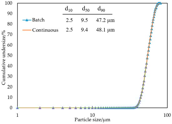
Figure 7.
Particle size distributions of batch- and continuous-ground ceramic slurries.
The d90, d50, and d10 values of batch- and continuous-ground porcelain body slurries were measured as 47.2, 9.5, and 2.5 µm and 48.1, 9.4, and 2.5 µm, respectively (Figure 7). Batch grinding produces a wider size distributed product in the grinding of one kind of raw material compared to continuous grinding [38]. However, in this study, a ceramic body composition consisting of clay, altered granite, kaolin, and feldspar and having different grinding characteristics was ground together in batch and continuous mills. In batch grinding, all raw materials were ground in the same environment from the beginning to the end of the grinding process. On the other hand, the raw materials started to be ground with larger balls in the 1st chamber, and then the finely ground materials passed to the 2nd chamber and continued to be ground with smaller sized balls. In this case, the plastic clay minerals, which were already fine-sized, were dispersed and passed into the 1st chamber, and left the mill together with other ground hard raw materials. Thus, due to the grinding and dispersing capabilities of different grinding methods according to raw material properties, the particle size distributions obtained in continuous and batch grinding were almost the same [39]. There was no significant difference in the particle size distributions for both mill types under the conditions studied from the laser particle size analyzer. On the other hand, chemical analysis was performed after sieving through a sieve with an opening of 38 µm to obtain the chemical differences according to the size fractions of ground slurries. The amount and properties of alkaline minerals, such as potassium and sodium feldspar, determine the sintering properties of ceramic materials. In this study, sodium, potassium, and silicon oxides of the −38 µm size group obtained from grinding batch and continuous milling were chemically analyzed in order to estimate the mineral type of the ground materials. The Na2O/K2O/SiO2 contents (wt.%) in the +38 µm size group were analyzed as 2.1/4.5/73.1 and 1.4/3.6/70.1 for the batch and continuous mill, respectively. Considering the Na2O/K2O/SiO2 contents, feldspathic and quartz minerals were more concentrated in the +38 µm size fraction in batch-ground materials, and this resulted in a higher water absorption due to the lower fluxing characteristics of coarse-sized feldspar and quartz minerals, which are assumed to have less surface area for reactions during the sintering process.
Batch- and continuous-ground ceramic slurries were dried with a spray dryer to obtain granules with a 6% moisture content. The granules were firstly shaped in a laboratory-based press at a specific pressure of 325 kg/cm2 in a 5 cm × 5 cm size and sintered at a maximum temperature of 1180 °C for 39 min to investigate their sintering characteristics (Table 6).
Table 6.
Sintering characteristic of continuous/batch-ground ceramic body.
The shrinkage, water absorption, L, a, b (color) values were 8.0%, 1.1%, 44.4, 10.2, 17.6 for batch- and 8.1%, 0.3%, 43.6, 10.2, 17.4 for continuous-ground ceramic bodies after sintering in floor tile conditions, respectively (Table 6). Grinding time is important for the color values of ceramic materials due to the different crystal and matrix formation [40]. However, no significant difference was found between the color values of bodies, and the dark sintering color was explained by the presence of metallic colorants such as hematite and anatase in the raw materials [41]. Additionally, the raw material particle size has significant effects on the sintering properties in ceramic floor tile bodies [42]. In the literature, it has been found that shrinkage and compressive strength increase as the particle size and water absorption decrease due to the decreasing pore diameter [43]. While there was no important difference between the shrinkage values of the samples, the difference in water absorption values indicated that feldspathic minerals, which reduced the melting temperature by forming eutectic or quartz and provided a glassy phase formation, were in a coarser particle size in batch grinding [44]. Quantitative XRD diagrams showing the phase analysis of sintered ceramic bodies prepared using continuous and batch grinding are shown in Figure 8.
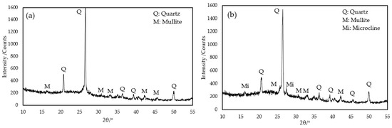
Figure 8.
XRD phase diagrams of sintered specimen prepared using continuous- (a) and batch- (b) ground ceramic bodies.
The XRD results showed that the sintered specimens obtained through continuous milling consisted of quartz and mullite, while the sintered body obtained through batch milling consisted of quartz, mullite, and microcline peaks. The presence of a microcline phase in the sintered composition obtained through batch grinding indicated the presence of unreacted potassium feldspar in the body. Feldspar is used to enhance the vitrification rate of porcelain ceramic bodies by decreasing the melting temperature of the glass phase with sodium and potassium elements [45]. In batch grinding, the plastic clay particles entered between feldspar and quartz minerals and made it difficult to grind hard minerals. For this reason, feldspar and quartz minerals could not be ground sufficiently compared to continuous grinding, and thus the vitrification rate of the ceramic body slowed down due to the presence of a coarse fraction of feldspar and quartz at −38 µm [46,47]. Clay group raw materials refer to minerals in the fine-size fraction in their natural state. Such minerals agglomerate and therefore appear to be coarse-sized in an aqueous medium [48]. In addition, clay minerals have different surface-edge electrical charges that attract each other with electrical forces, and the energy spent to overcome this force by separating the clay minerals into fine-sized particles is considerably lower than the energy required to reduce the particle size of non-plastic coarse minerals such as feldspar and quartz. Therefore, scrubbing or mixing methods are usually sufficient to remove agglomerated clay grains from each other and bring them to a fine particle size [49]. In continuous milling, clay minerals were reduced to a fine size in the first stage by rotation and agitation, and fine-sized clay minerals remain in the up-flow of the slurry. Coarse-sized feldspar and quartz minerals collapsed in the slurry and remained between the balls, and a more efficient grinding was realized compared to batch grinding. Thus, the feldspar and quartz minerals remained in the fine fraction of the −38 µm size group, and the energy required for sintering was lower than that obtained in batch grinding. The vitrification rate and glassy phase/mullite proportion increment resulted in a decrease in water absorption. In addition, the fine ball size distribution of second-stage continuous milling enhanced the particle size reduction in feldspar/quartz minerals and the ceramic properties of the sintered body.
DTA and TG analyses were performed to determine the behavior of continuous- and batch-ground bodies in terms of mass loss and energy changes against temperature increase (Figure 9).

Figure 9.
DTA/TG diagrams of sintered specimen prepared using continuous- (a) and batch- (b) ground glazed porcelain ceramics.
As seen from Figure 8, both curves have similar diagrams for continuous- and batch-ground bodies. The initial mass loss upon heating up to 200 °C was due to the release of adsorbed moisture in the samples. The removal of chemically bound water, which was particularly dependent on the structure of clay minerals, was detected by endothermic peaks in the 200–350 °C temperature range. The endothermic change seen at 266 and 274 °C in the DTA curve of the continuous- and batch-prepared samples showed that chemically bound water in the structure of clay minerals was removed. However, dehydroxylation of the kaolinite-type clay mineral was observed with the endothermic peak seen in the 450–650 °C range. Such peaks were determined as 566 and 594 °C for continuous- and batch-prepared bodies, respectively. The exothermic α→β phase transformation of quartz in the ceramic structure was also one of the important sources of peak formation in this region. In the 900–1000 °C range, dehydroxylated kaolinite transformed into mullite crystals through an exothermic reaction. The mullite formation temperatures of samples prepared through continuous and batch methods were 900 and 918 °C, respectively. Bragança and Bergmann (2006) found that a finer particle size resulted in high thermal expansion values compared to coarse-sized composition due to the increased surface area [50]. However, in this study, DTA and TG curves showed that reaction temperatures and mass losses occur at lower temperatures in continuous milling than in batch ones. The fact that reactions in the bodies prepared with the same raw materials occur at high temperatures indicated that kaolinite group clay minerals did not reach a fine enough particle size. This meant that the formation of mullite would be less in the body prepared with batch milling compared to the continuous method.
SEM and EDS analyses were carried out for HF-treated (Figure 10a,b) and nontreated (Figure 10c,d) surfaces for batch- and continuous-prepared sintered samples to examine the crystal morphology and observe the chemical differences on the surface.
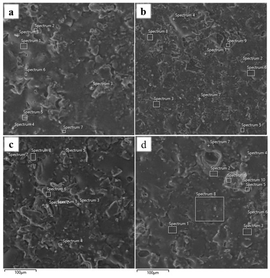
Figure 10.
(a) Batch HF-treated, (b) continuous HF-treated, (c) batch untreated surface, (d) continuous untreated surface.
The SEM-EDS analysis revealed that the ceramic structure was formed of glassy phase and mullite crystals for both sintered specimens, in general, as evaluated with XRD data (Figure 8). From the SEM-EDS analysis of untreated samples, considerable amounts of iron were observed as solved in the glass phase. The chemical compositions for Spectrum 5, Figure 10c, and Spectrum 4 in Figure 10d were analyzed as having 64.6% FeO, 25.3% SiO2, and 94.6% SiO2 content, respectively, which supported the glass phase for untreated samples. The glass phase was dissolved from samples with HF acid treatment to investigate crystal phase formation in sintered compositions. High Al2O3/SiO2 contents of 39.7/52.1% for Spectrum 4 in Figure 10a and 23.4/59.2% for Spectrum 3 in Figure 10b enhanced the mullite formation in the sintered compositions. However, the distribution of aluminum and silicon elements in the EDS analysis of the batch-prepared sample showed that the mullite amount was higher in the sample prepared through the continuous method. Na and K peaks seen around the mullite crystals in both samples indicated the existence of unreacted feldspar particles. In Figure 10a, Na2O was found to be 5.1% for Spectrum 5, while, in Figure 10b, K2O was found to be 7.4% for Spectrum 8, supporting the presence of feldspar in the compositions. On the other hand, spectra with high silicon content in both samples demonstrated residual quartz in the structure. EDS spectra for Figure 10 are given in Appendix C.
The AFM images were taken to examine the surface roughness and topography of sintered samples obtained through continuous and batch milling. Three-dimensional topography and phase images of samples that had a maximum roughness were given with a scale bar in Figure 11.
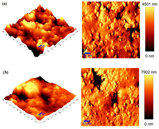
Figure 11.
AFM images of sintered specimens prepared using (a) continuous and (b) batch grinding.
In the AFM images, Sa/Sq values expressing the surface roughness of sintered tablets prepared using continuous and batch methods were obtained as 1414.6 ± 156.4/1842.5 ± 235.4 nm and 1584.1 ± 267.2/1960.1 ± 353.1 nm, respectively. The surface roughness values of the samples prepared using the batch method were higher than the continuous ones. In particular, unreacted coarse feldspar and quartz particles were the most important factors that increased the roughness values. Both the porosity and roughness increment result in decoration problems in glazed porcelain products, or can cause porosity in the polished porcelain tile microstructure that could lower its resistance to staining [51].
4. Conclusions
Different kinds of economic and technical impacts were observed for batch/continuous mills on the grinding and sintering properties of ceramic bodies. Changing the mill speed during the grinding process in the batch mill affected the grinding efficiency. Energy consumption/capacity values were calculated as 36.4 kW/ton/1.60 ton/h and 37.4 kW/ton/1.56 ton/h in batch mill experiments at variable (3rd regime) and constant (16 rpm) mill speeds, respectively. In other words, varying the mill rotational speed during the grinding process positively affected the grinding efficiency compared to a permanent speed in a batch mill. A considerably higher capacity was achieved with the continuous mill compared to the batch one. On the other hand, the batch mill used less energy in terms of specific energy consumption. However, the chambers of the continuous mill provided the overflow of finely ground materials passing to the second chamber; therefore, more efficient grinding was ensured compared to the batch mill. The fact that plastic clay minerals remained in the grinding environment during the process in the batch mill caused hard minerals such as feldspar and quartz to remain coarser than in the continuous mill. Such coarse-sized hard minerals made it difficult for particles to react with each other in the sintering step due to the lower surface area. For this reason, unreacted microcline peaks were detected in the phase analysis of the sintered body prepared through batch grinding. The difference in reaction temperatures observed in the DTA/TG curves and water absorption values after sintering confirmed the situation. It was understood from the SEM images that especially ferrous compounds originated from raw materials dissolved in the glassy phase, and this was the reason for the dark color. In addition, the high aluminum and silicon peak values obtained from EDS spectra showed that mullite formation was higher in the continuous sample. In addition, the AFM results also showed that the roughness values of sintered samples prepared through batch grinding were higher than samples prepared through continuous grinding. As a result, EN 14411 Group BIb, with a water absorption value of 0.5%–3% for batch grinding as a floor tile, and EN 14411 Group BIa, with a lower water absorption value < 0.5% for continuous grinding as a porcelain or glazed porcelain tile, could be produced within the scope of this study [52]. Although the initial investment costs of continuous mills are high, the smaller installation area provides an advantage over the batch mill. Furthermore, it is seen that the capacity of approximately five batch mills can be reached with one continuous mill within the scope of the operation. When comparing the properties of the ground products in terms of ceramic structure, grinding plastic clay minerals in a batch mill creates a cushioning effect, making it more difficult to achieve a sufficient fineness for the grinding of hard raw materials than in a continuous mill. Additionally, more time is lost in batch mills during the feeding and discharging stages. In general, except for the initial investment cost, all other criteria indicate that the selection of a continuous mill will provide a more efficient ceramic preparation process.
Funding
This work was supported by Çanakkale Onsekiz Mart University The Scientific Research Coordination Unit, Project number: FBA-2024-4812.
Data Availability Statement
Data is contained within the article.
Acknowledgments
Thanks to the Kaleseramik R&D Center for the technical support.
Conflicts of Interest
The author declares no conflicts of interest.
Appendix A


Figure A1.
XRD patterns of (a) clay, (b) altered granite, (c) kaolin, and (d) feldspar.
Appendix B
Table A1.
Complete particle size distributions of the batch/continuous-ground products.
Table A1.
Complete particle size distributions of the batch/continuous-ground products.
| Size (µm) | % Volume Under for Batch-Ground Material | % Volume Under for Continuous-Ground Material |
|---|---|---|
| 0.767 | 0 | 0 |
| 0.872 | 0.14 | 0 |
| 0.991 | 0.42 | 0.27 |
| 1.13 | 0.86 | 0.64 |
| 1.28 | 1.52 | 1.25 |
| 1.45 | 2.41 | 2.13 |
| 1.65 | 3.65 | 3.34 |
| 1.88 | 5.24 | 4.93 |
| 2.13 | 7.22 | 6.91 |
| 2.42 | 9.9 | 9.29 |
| 2.75 | 12.36 | 12.06 |
| 3.12 | 15.49 | 15.1 |
| 3.55 | 18.95 | 18.63 |
| 4.03 | 22.57 | 22.37 |
| 4.58 | 25.51 | 26.34 |
| 5.21 | 30.7 | 30.4 |
| 5.92 | 34.85 | 34.71 |
| 6.72 | 38.82 | 38.97 |
| 7.64 | 42.54 | 42.21 |
| 8.68 | 47.57 | 47.36 |
| 9.86 | 51.06 | 51.41 |
| 11.2 | 54.87 | 55.22 |
| 12.7 | 58.53 | 59.1 |
| 14.5 | 62.06 | 62.75 |
| 16.4 | 65.53 | 66.27 |
| 18.7 | 68.91 | 69.58 |
| 21.2 | 72.21 | 72.96 |
| 24.1 | 75.44 | 76.12 |
| 27.4 | 78.56 | 79.12 |
| 31.1 | 81.96 | 81.96 |
| 35.3 | 84.39 | 84.59 |
| 40.1 | 87.02 | 87.01 |
| 45.6 | 89.41 | 89.19 |
| 51.8 | 91.56 | 91.14 |
| 58.9 | 93.44 | 92.85 |
| 66.9 | 95.06 | 94.35 |
| 76 | 95.43 | 95.53 |
| 86.4 | 97.54 | 96.71 |
| 98.1 | 98.42 | 97.6 |
| 111 | 99.08 | 98.31 |
| 127 | 99.55 | 98.84 |
| 144 | 99.84 | 99.23 |
| 163 | 100 | 99.5 |
| 186 | 100 | 99.59 |
| 211 | 100 | 99.82 |
| 240 | 100 | 99.92 |
| 272 | 100 | 100 |
Appendix C


Figure A2.
EDS spectra corresponding to Figure 10.
References
- Ferrara, L.; Deegan, P.; Pattarini, A.; Sonebi, M.; Taylor, S. Recycling Ceramic Waste Powder: Effects Its Grain-Size Distribution on Fresh and Hardened Properties of Cement Pastes/Mortars Formulated from SCC Mixes. J. Sustain. Cem.-Based Mater. 2019, 8, 145–160. [Google Scholar] [CrossRef]
- Framinan, J.M.; Leisten, R.; García, R.R. A Case Study: Ceramic Tile Production. In Springer eBooks; Springer: Berlin/Heidelberg, Germany, 2014; pp. 371–395. [Google Scholar]
- Sahishna, S.S.; Subash Chandran, M.P.; Prasobh, G.R.; Akhila, J.B.; Rejakumar, P.; Renjini, A.S. An overview on blushing powder. Int. J. Pharm. Res. Appl. 2022, 7, 1043–1050. [Google Scholar]
- Durgut, E.; Cinar, M.; Terzi, M.; Unver, I.K.; Yildirim, Y.; Boylu, F.; Ozdemir, O. Effect of Blunging/Dispersion Parameters on Separation of Halloysite Nanotubes from Gangue Minerals. Minerals 2022, 12, 683. [Google Scholar] [CrossRef]
- Kumar, A.; Sahu, R.; Tripathy, S.K. Energy-Efficient Advanced Ultrafine Grinding of Particles Using Stirred Mills—A Review. Energies 2023, 16, 5277. [Google Scholar] [CrossRef]
- Gürcan, K.; Derïn, B.; Ayas, E. Effect of SIC Particle Size on the Microstructural, Mechanical and Oxidation Properties of in-Situ Synthesized HFB2-SIC Composites. J. Polytech. 2020, 24, 503–510. [Google Scholar] [CrossRef]
- Ranogajec, J.; Djuric, M.; Radeka, M.; Jovanic, P. Influence of Particle Size and Furnace Atmosphere on the Sintering of Powder for Tiles Production. Ceramics 2000, 44, 71–77. [Google Scholar]
- Zheng, W.; Cui, T.; Li, H.; Yang, Y. Novel Dry-Suspension Granulation Process for Preparing Pressed Powders of Ceramic Tiles. Powder Technol. 2020, 377, 274–280. [Google Scholar] [CrossRef]
- Olhero, S.M.; Ferreira, J.M.F. Influence of Particle Size Distribution on Rheology and Particle Packing of Silica-Based Suspensions. Powder Technol. 2003, 139, 69–75. [Google Scholar] [CrossRef]
- Moraga, C.; Astudillo, C.A.; Estay, R.; Maranek, A. Enhancing Comminution Process Modeling in Mineral Processing: A Conjoint Analysis Approach for Implementing Neural Networks with Limited Data. Mining 2024, 4, 966–982. [Google Scholar] [CrossRef]
- Ozsoysal, S.; Heidari, H.; Guner, G.; Clancy, D.J.; Bilgili, E. Modeling Power Consumption: A Novel Correlation for Stirred Media Mills with Variable Bead Filling Ratios. Deleted J. 2025, 2, 14. [Google Scholar] [CrossRef]
- Toprak, N.A.; Benzer, A.H.; Karahan, C.E.; Zencirci, E.S. Effects of Grinding Aid Dosage on Circuit Performance and Cement Fineness. Constr. Build. Mater. 2020, 265, 120707. [Google Scholar] [CrossRef]
- Wills, B.A.; Finch, J.A. Grinding Mills. In Elsevier eBooks; Elsevier: Amsterdam, The Netherlands, 2015; pp. 147–179. [Google Scholar]
- Matsanga, N.; Nheta, W.; Chimwani, N. A Review of the Grinding Media in Ball Mills for Mineral Processing. Minerals 2023, 13, 1373. [Google Scholar] [CrossRef]
- Yu, W.; Lv, B.; Yuan, J. Wear Model of Silicon Nitride Ceramic Balls in Three-Body Coupling Grinding Mode. Appl. Sci. 2023, 13, 5796. [Google Scholar] [CrossRef]
- Lv, J.; Wang, Z.; Ma, S. Calculation Method and Its Application for Energy Consumption of Ball Mills in Ceramic Industry Based on Power Feature Deployment. Adv. Appl. Ceram. Struct. Funct. Bioceram. 2020, 119, 183–194. [Google Scholar] [CrossRef]
- Carlos, E.; De Aguiar, P.R.; Eduardo, A.; Chinali, R. Optimization of Ceramics Grinding. In InTech eBooks; InTech: Toulon, France, 2011. [Google Scholar]
- Hogg, R.; Cho, H. A Review of Breakage Behavior in Fine Grinding by Stirred-Media Milling. KONA Powder Part. J. 2000, 18, 9–19. [Google Scholar] [CrossRef]
- Yang, J.; Li, Y.; Zhu, P.; Guo, R.; Li, H.; Ma, S.; Wang, D. Study on Impact and Abrasion Resistance of Minerals Based on JK Drop Weight Test and Grinding Test. Minerals 2025, 15, 407. [Google Scholar] [CrossRef]
- Yu, J.; Jin, S.-H.; Raju, K.; Lee, Y.; Lee, H.-K. Analysis of Individual and Interaction Effects of Processing Parameters on Wet Grinding Performance in Ball Milling of Alumina Ceramics Using Statistical Methods. Ceram. Int. 2021, 47, 31202–31213. [Google Scholar] [CrossRef]
- Yuan, C.; Wu, C.; Fang, X.; Liao, N.; Tong, J.; Yu, C. Effect of Slurry Concentration on the Ceramic Ball Grinding Characteristics of Magnetite. Minerals 2022, 12, 1569. [Google Scholar] [CrossRef]
- Heim, A.; Olejnik, T.P.; Pawlak, A. Rate of Ceramic Body Grinding in a Ball Mill. Physicochem. Probl. Miner. Process. 2005, 39, 189–198. [Google Scholar]
- Das, S.; Anil, L.; Pandivelan, C. Design and Development of an Ultrasonic Stack Assembly for Ultrasonic Vibration Assisted Grinding. Mater. Today Proc. 2021, 46, 8778–8782. [Google Scholar] [CrossRef]
- Celis, C.; Antoniou, A.; Cuisano, J.; Pillihuaman, A.; Maza, D. Experimental Characterization of Chalcopyrite Ball Mill Grinding Processes in Batch and Continuous Flow Processing Modes to Reduce Energy Consumption. J. Mater. Res. Technol. 2021, 15, 5428–5444. [Google Scholar] [CrossRef]
- Yan, H.; Deng, F.; Niu, H.; Zhu, J.; Hu, B. Effect of Grinding Parameters on Surface Quality in Internal Grinding of Silicon Nitride Ceramics. J. Braz. Soc. Mech. Sci. Eng. 2021, 43, 353. [Google Scholar] [CrossRef]
- Yuan, C.; Wu, C.; Ling, L.; Yao, X.; Li, Z.; Xie, F.; Tian, J. Ceramic Grinding Kinetics of Fine Magnetite Ores in the Batch Ball Mill. Minerals 2023, 13, 1188. [Google Scholar] [CrossRef]
- He, M.; Wang, Y.; Forssberg, E. Parameter Studies on the Rheology of Limestone Slurries. Int. J. Miner. Process. 2005, 78, 63–77. [Google Scholar] [CrossRef]
- Makokha, A.B.; Moys, M.H.; Muumbo, A.M.; Kiprono, R.J. Optimization of In-Mill Ball Loading and Slurry Solids Concentration in Grinding of UG-2 Ores: A Statistical Experimental Design Approach. Miner. Eng. 2012, 39, 149–155. [Google Scholar] [CrossRef]
- Tang, B.; Cheng, B.; Song, X.; Ji, H.; Li, Y.; Wang, Z. Experimental Study on the Influence of Rotational Speed on Grinding Efficiency for the Vertical Stirred Mill. Minerals 2024, 14, 1208. [Google Scholar] [CrossRef]
- El-Eskandarany, M.S. Controlling the Powder Milling Process. In Elsevier eBooks; Elsevier: Amsterdam, The Netherlands, 2015; pp. 48–83. [Google Scholar]
- Bond, F.C. Crushing and grinding calculations. Part I, Brit. Chem. Eng. 1961, 6, 378–385. Available online: https://www.911metallurgist.com/blog/wp-content/uploads/2015/11/Bond-F-C-1961-Crushing-and-Grinding-Calculations.pdf (accessed on 11 September 2025).
- EN-ISO 10545-3; Ceramic Tiles Part 3: Determination of Water Absorption, Apparent Porosity, Apparent Relative Density and Bulk Density. European Committee for Standardization: Brussels, Belgium, 2018.
- Dong, H.; Moys, M.H. Measurement of Impact Behaviour between Balls and Walls in Grinding Mills. Miner. Eng. 2003, 16, 543–550. [Google Scholar] [CrossRef]
- Panjipour, R.; Barani, K. The Effect of Ball Size Distribution on Power Draw, Charge Motion and Breakage Mechanism of Tumbling Ball Mill by Discrete Element Method (DEM) Simulation. Physicochem. Probl. Miner. Process. 2017, 54, 258–269. [Google Scholar] [CrossRef]
- AmanNejad, M.; Barani, K. Effects of Ball Size Distribution and Mill Speed and Their Interactions on Ball Milling Using DEM. Miner. Process. Extr. Metall. Rev. 2020, 42, 374–379. [Google Scholar] [CrossRef]
- Naumenko, Y.; Deineka, K. Building a Model of the Compression Grinding Mechanism in a Tumbling Mill Based on Data Visualization. East.-Eur. J. Enterp. Technol. 2023, 5, 64–72. [Google Scholar] [CrossRef]
- Parapari, P.S.; Parian, M.; Rosenkranz, J. Breakage Process of Mineral Processing Comminution Machines—An Approach to Liberation. Adv. Powder Technol. 2020, 31, 3669–3685. [Google Scholar] [CrossRef]
- Gupta, V.K. Hold-up Weight in Continuous Wet Ball Milling: Relationship with the Size Distribution of the Particulate Contents of the Mill. Powder Technol. 2022, 415, 118137. [Google Scholar] [CrossRef]
- Ipek, H.; Ucbas, Y.; Yekeler, M.; Hosten, Ç. Grinding of Ceramic Raw Materials by a Standard Bond Mill: Quartz, Kaolin and K-Feldspar. Miner. Process. Extr. Metall. Trans. Inst. Min. Metall. Sect. C 2005, 114, 213–218. [Google Scholar] [CrossRef]
- Yıldız, B. Effect of Particle Size Distribution on the Properties of Celsian Based Glazes. J. Aust. Ceram. Soc. 2024, 60, 1495–1504. [Google Scholar] [CrossRef]
- Lemougna, P.N.; Yliniemi, J.; Ismailov, A.; Levanen, E.; Tanskanen, P.; Kinnunen, P.; Roning, J.; Illikainen, M. Spodumene Tailings for Porcelain and Structural Materials: Effect of Temperature (1050–1200 °C) on the Sintering and Properties. Miner. Eng. 2019, 141, 105843. [Google Scholar] [CrossRef]
- Qian, C.; Hu, K.; Wang, H.; Nie, L.; Feng, Q.; Lu, Z.; Li, P.; Lu, K. The Effect of Particle Size Distribution on the Microstructure and Properties of Al2O3 Ceramics Formed by Stereolithography. Ceram. Int. 2022, 48, 21600–21609. [Google Scholar] [CrossRef]
- Çakar, E.Z.; Akbay, A.; Zırtıl, O.; Altınok, İ. Investigation of Effects Different Particle Size Quartz and Feldspar on Body Physical Properties. Int. J. Eng. Res. Dev. 2024, 17, 498–508. [Google Scholar]
- Alves, H.J.; Melchiades, F.G.; Boschi, A.O. Effect of Feldspar Particle Size on the Porous Microstructure and Stain Resistance of Polished Porcelain Tiles. J. Eur. Ceram. Soc. 2012, 32, 2095–2102. [Google Scholar] [CrossRef]
- Fuertes, V.; Reinosa, J.J.; Fernández, J.F.; Enríquez, E. Engineered Feldspar-Based Ceramics: A Review of Their Potential in Ceramic Industry. J. Eur. Ceram. Soc. 2021, 42, 307–326. [Google Scholar] [CrossRef]
- Garzón, E.; Pérez-Villarejo, L.; Eliche-Quesada, D.; Martínez-Martínez, S.; Sánchez-Soto, P.J. Vitrification Rate and Estimation of the Optimum Firing Conditions of Ceramic Materials from Raw Clays: A Review. Ceram. Int. 2022, 48, 15889–15898. [Google Scholar] [CrossRef]
- Koca, K.; Benkli, Y.E. Microstructural and Elemental Characterization of Pumice–Bauxite–Clay Ceramics: Effects of Sintering Temperature and Scherrer-Based Analysis. J. Aust. Ceram. Soc. 2025. [Google Scholar] [CrossRef]
- Huggett, J.M. Clay Minerals, Reference Module in Earth Systems and Environmental Sciences; Elsevier: Amsterdam, The Netherlands, 2015. [Google Scholar] [CrossRef]
- Durgut, E.; Cinar, M.; Ozdemir, O. Effect of Calcite and Mica Contents in Nepheline Syenite Samples on the Ceramic Body Sintering Behaviours and Surface Roughness. Physicochem. Probl. Miner. Process. 2022, 58, 149179. [Google Scholar] [CrossRef]
- Bragança, S.R.; Bergmann, C.P. Effect of Quartz of Fine Particle Size on Porcelain Properties. Mater. Sci. Forum 2006, 530–531, 493–498. [Google Scholar] [CrossRef]
- Rambaldi, E.; Lucchese, B.; Engels, M.; Bignozzi, M.C. Evaluation of Durability and Cleanability Performances of Protective Treatments for Lapped Ceramic Tiles—Part 2. Int. J. Appl. Ceram. Technol. 2018, 16, 625–637. [Google Scholar] [CrossRef]
- EN 14411; Ceramic Tiles—Definition, Classification, Characteristics, Assessment and Verification of Constancy of Performance and Marking. European Committee for Standardization: Brussels, Belgium, 2016.
Disclaimer/Publisher’s Note: The statements, opinions and data contained in all publications are solely those of the individual author(s) and contributor(s) and not of MDPI and/or the editor(s). MDPI and/or the editor(s) disclaim responsibility for any injury to people or property resulting from any ideas, methods, instructions or products referred to in the content. |
© 2025 by the author. Licensee MDPI, Basel, Switzerland. This article is an open access article distributed under the terms and conditions of the Creative Commons Attribution (CC BY) license (https://creativecommons.org/licenses/by/4.0/).