Article

Investigation of the Testing Method of Softening–Melting Properties of Iron-Bearing Materials

1
Key Laboratory for Ecological Metallurgy of Multimetallic Mineral (Ministry of Education), Northeastern University, Shenyang 110819, China
2
School of Metallurgy, Northeastern University, Shenyang 110819, China
3
Ironmaking Department, Beijing Shougang Co., Ltd., Tangshan 064400, China
*
Author to whom correspondence should be addressed.
Minerals 2024, 14(12), 1214; https://doi.org/10.3390/min14121214
Submission received: 30 October 2024 / Revised: 18 November 2024 / Accepted: 19 November 2024 / Published: 28 November 2024
(This article belongs to the Section Mineral Processing and Extractive Metallurgy)

Abstract

:
The softening–melting properties of iron-bearing materials play a crucial role in the reduction process in the lumpy zone in the blast furnace (BF) and affect the height, thickness, and shape of the cohesive zone, as well as gas permeability in the BF. A novel softening–melting method was developed based on actual BF production practices, which consistently matches the reduction index and metallization degree observed in actual BF operations compared to the conventional methods. Under the novel softening–melting testing method, the characteristic temperatures (T40 and TS) increase by about 5 °C and 49 °C, respectively, compared to the conventional method. Additionally, the permeability index (S) of the sinter in the novel method is about 707 kPa·°C lower compared to the conventional method. Clearly, the novel method results in higher softening–melting characteristic temperatures for iron-bearing materials compared to the traditional method, more closely matching actual BF conditions. This approach can provide valuable insights for improving gas permeability and enhancing the reduction process of iron-bearing materials in the BF.

1. Introduction

The cohesive zone, situated between the lumpy zone and the dripping zone within the blast furnace (BF), plays a crucial role in distributing BF gas flow, permeability, and heat transfer. This zone facilitates full interaction between iron-bearing materials and BF gas, initiating solid–liquid–gas multiphase reactions that effectively separate slag and iron [1,2,3]. Specifically, the softening–melting properties of iron-bearing materials are significant in the reduction process of the lumpy zone, determining the height, thickness, and shape of the cohesive zone and influencing permeability throughout the BF production process [4,5,6].
The softening–melting properties of iron-bearing materials play a significant role in the cohesive zone and BF permeability, and current test methods include high-temperature experiments, physical models or simulators, and various numerical simulations of the BF [7]. The temperature profile, gas composition, and load parameters are of significance in simulating the reducing, softening–melting, and dripping processes of the BF during high-temperature softening–melting methods. Researchers have employed various constant temperature rates, such as 200 °C/h [8], 3 °C/min [9,10,11,12,13,14], 10 °C/min [15,16], and 50–60 °C/min [17]. However, the current trend favors a stepwise method with isothermal holding, which has constant temperature rates instead. For instance, the heating rate is controlled at 10 °C/min below 900 °C, while temperatures above 900 °C are controlled at a rate of 5 °C/min, with an isothermal hold at 900 °C for 30 min [5,18].
Furthermore, the gas composition is controlled to shift gradually from an inert gas [8,10,11,13,14,19,20] to a different component [5,8,9,11,19,21,22,23,24] during the heating process. In softening–melting methods, the load is adjusted to 0.05 MPa [25], 0.1 MPa [13,26,27], and 0.15 MPa [28]. However, the current method emphasizes a stepwise approach rather than constant loading routines [13]. For instance, temperatures below 900 °C are maintained at a pressure of 0.05 MPa, whereas temperatures above 900 °C are adjusted to a pressure of 0.1 MPa [5,21,22,29].
However, challenges still remain in the softening–melting method process of iron-bearing materials so far. The iron-bearing materials undergo a series of processes, including reducing, softening–melting, and dripping, which typically take around 6–7 h in the BF [30]. During this time, the temperature range for the gas–solid reaction reduction process is generally between 700 °C and 1000 °C, with the reduction process lasting for approximately 3–4 h within the lumpy zone [31]. It is important to note that the gas–solid reaction time of the iron-bearing materials in conventional softening–melting methods is significantly shorter than that observed in an actual BF. Additionally, the changes in reduction index and metallization degree observed in these methods are not consistent with typical conditions found in an actual BF.
In addition to the properties of the iron-bearing materials themselves, the factors that have a significant impact on the test results include method indices such as the temperature rate, reduction time, and load. A novel softening–melting method has been designed, with main research focuses and original contributions including (1) a softening–melting method that has been proposed to closely approximate actual BF conditions. (2) Key indices for the novel method, including temperature rate, reduction time, and load, are defined. (3) Variations in these indices under the novel method are analyzed. These adjustments of the softening–melting properties of iron-bearing materials are effectively consistent with those observed in the cohesive zone of an actual BF, reflecting practical production practices.

2. Experiments

2.1. Materials

In the experiment, the sinter, pellet, and coke materials were provided by a commercial steel company. The sinter and pellet diameter ranged from 10.0 mm to 12.5 mm, while the coke diameter ranged from 5.0 mm to 10.0 mm. The chemical composition of the sinter and pellet, along with the proximate analysis of the coke, is detailed in Table 1 and Table 2, respectively.

2.2. Softening–Melting (S&M) Under Load Method

The softening–melting properties of the iron-bearing materials were studied using the RSZ-03 Ore Metallurgical Properties Comprehensive Measuring Instrument (Northeastern University, Shenyang, China). The S&M under load method (RSZ-03) is shown in Figure 1. The samples were stacked in a graphite crucible with a diameter of 75 mm. The bottom of the crucible features Φ10 drip holes to allow the melt to drip smoothly and vent holes for the passage of gas. The iron-bearing materials are typically sandwiched between two layers of coke, with the weight of the iron-bearing materials being 500 g. The upper layer of coke weighs 30 g, while the lower layer of coke weighs 90 g. Additionally, the samples are subjected to a load through a pushing system, which consists of a graphite ram on one end and a feed-through on the other.
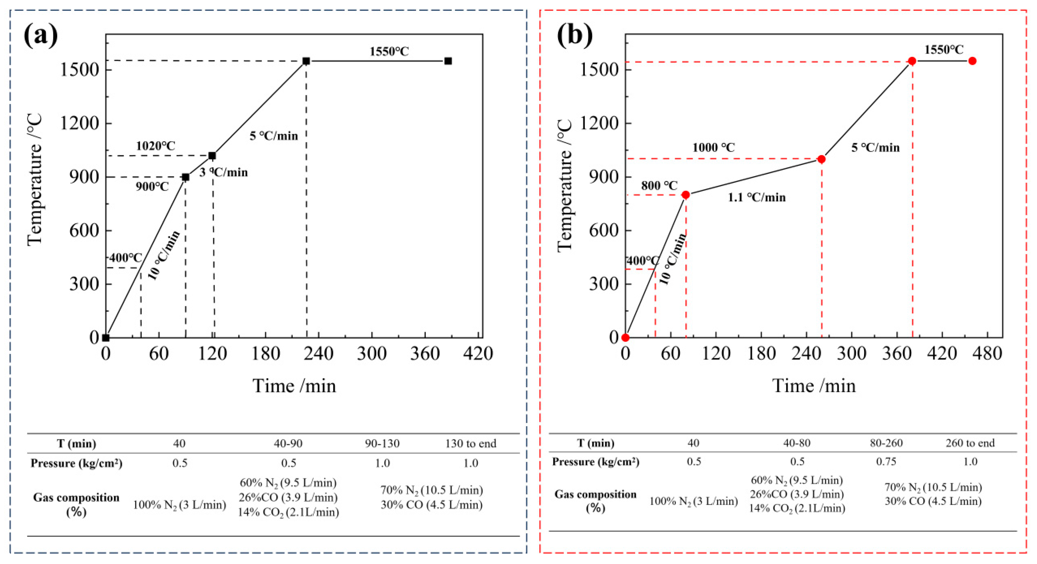
The test results significantly influence the softening–melting properties of iron-bearing materials and reduction indices, such as temperature rate, reduction time, and load. The conventional softening–melting method (a) and novel softening–melting method (b) for S&M under the load method are depicted in Figure 2. In Figure 2a, the conventional softening–melting method (CSMM) is widely adopted. It begins by heating the iron-bearing materials from room temperature to 400 °C in an N2 atmosphere at a flow rate of 3 L/min under a load of 0.5 kg/cm2. As the temperature rises beyond 400 °C but remains below 900 °C, the load is maintained at 0.5 kg/cm2, while the gas atmosphere shifts to 9.5 L/min of N2, 3.9 L/min of CO, and 2.1 L/min of CO2. Once temperatures exceed 900 °C, the load is increased to 1.0 kg/cm2, and the reducing gas changes to 10.5 L/min of N2 until the end, followed by 4.5 L/min of CO. Additionally, the applied pressure load is 0.5 kg/cm2 for the first 90 min, after which it increases to 1.0 kg/cm2.
In contrast, Figure 2b illustrates the novel softening–melting method (NSMM) used for processing iron-bearing materials. Initially, the burden is heated from room temperature to 400 °C in an N2 atmosphere at a flow rate of 3 L/min. As the temperature rises from 400 °C to 800 °C, the atmosphere shifts to 9.5 L/min of N2, 3.9 L/min of CO, and 2.1 L/min of CO2. Beyond 800 °C, the iron-bearing materials continue to be heated under an atmosphere of 10.5 L/min of N2 and 4.5 L/min of CO. Additionally, the applied pressure load gradually increases from 0.5 kg/cm2 to 0.75 kg/cm2 between 40 min and 80 min and then reaches 1.0 kg/cm2.
During the softening–melting process, the computer automatically recorded and generated the softening–melting indices of the burden, which are detailed in Table 3.

2.3. Quenching Experiment

To explore the softening–melting properties between conventional and novel softening–melting methods and to analyze the mechanism behind the changes in the softening–melting behavior of the burden, quenching experiments were conducted at various temperatures. Figure 3 illustrates a schematic diagram of the softening–melting property curves, showcasing the results of these experiments. In investigating the reduction index (RI) and metallization degree (MD) of the burden in softening–melting methods, sample points were selected at temperatures of 700 °C, 800 °C, 900 °C, 1000 °C, 1200 °C, and characteristic temperatures of T10, T40, and Ts. The iron-bearing materials, after being cooled from the desired temperature to room temperature, were put in an N2 atmosphere at a flow rate of 5 L/min. Afterward, the graphite crucible was vertically cut into various smaller samples for further investigation using techniques such as the chemical analysis method.

3. Results

3.1. Reduction Index in Gas–Solid Reduction

In general, iron-bearing materials undergo a 3 h gas–solid reduction process in a reducing atmosphere, as outlined in GB/T 13241-2017. This duration is selected to simulate the reduction potential of the lumpy zone in the BF and to provide insights into softening–melting properties. During this process, the temperature typically ranges between 700 °C and 1000 °C, with the reduction phase lasting approximately 3–4 h within the lumpy zone [31]. The reduction time of the conventional softening–melting method (CSMM) from 800 °C to 1000 °C is confirmed to be nearly 43 min. However, as this duration is significantly short of the actual reduction time observed in the lumpy zone of BF, the novel softening–melting method (NSMM) was developed. The NSMM extends the reduction time to nearly 180 min, consisting more closely with the BF production practices.
The reduction indices under the conventional softening–melting method (CSMM) and the novel softening–melting method (NSMM), which simulate the reduction process of the iron-bearing materials in the lumpy zone in an actual BF, are defined as RIC1000 and RIN1000, respectively. These data are presented in Table 4. According to the table, the RIC1000 and RIN1000 values for the sinter are 25.41% and 59.58%, respectively. In contrast, the pellet exhibits relatively poorer reduction properties, with RIC1000 and RIN1000 values confirmed at 14.95% and 40.34%, respectively.
Additionally, Shen et al. [32] have developed a three-dimensional mathematical model to describe the internal state of a BF, including multiphase flow, thermochemical behavior, and process indicators. Their research indicates that the reduction indices in the lumpy zone gradually increase from 0% to 50% upon reaching the cohesive zone. This observation is consistent with the RIN1000 values of the sinter and pellet, which are confirmed at 59.58% and 40.34%, respectively. Remarkably, the reduction index in the gas–solid reduction of the NSMM is closely consistent with the predictions of the three-dimensional mathematical model.

3.2. Comparison Between the Tested Data and Actual BF

To investigate the mechanism of the burden reduction index in the BF softening–melting process, quenching experiments were conducted on sample points, as illustrated in Figure 3. These sample points were carefully chosen across a temperature range from 700 °C to 1200 °C, which includes characteristic temperatures like T10, T40, and TS. The outcomes of these experiments are detailed in Figure 4.
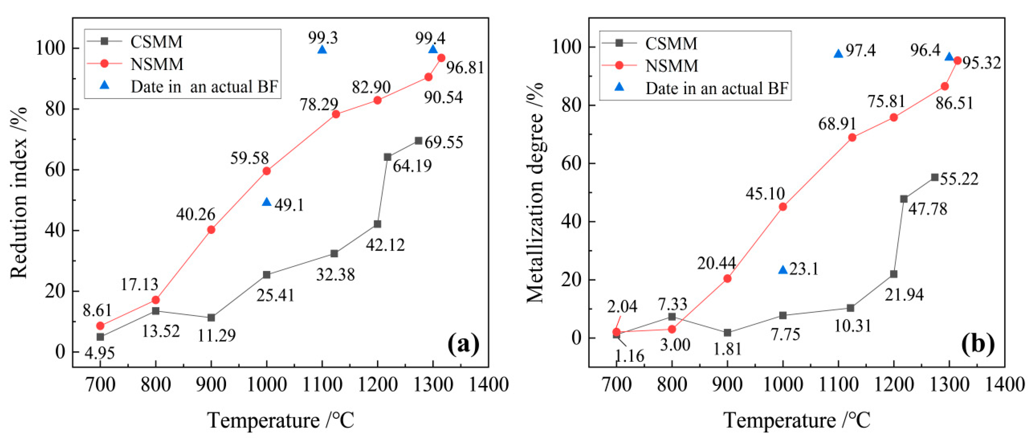
Figure 4 presents the reduction index and metallization degree of the sinter in quenching experiments conducted at temperatures ranging from 700 °C to 1200 °C, including the characteristic temperatures T10, T40, and TS. It outlines the reduction indices for the sintered conventional softening–melting method (CSMM) and the novel softening–melting method (NSMM), denoted by RI, at different temperature intervals. The reduction indices for CSMM are noted as 4.95%, 13.52%, 11.29%, 25.41%, 32.38%, 42.12%, 64.19%, and 69.55% at respective temperatures, whereas for NSMM, they are confirmed as 8.61%, 17.13%, 40.26%, 59.58%, 78.29%, 82.90%, 90.54%, and 96.81%. The MD for CSMM is noted as 1.16%, 7.33%, 1.81%, 7.75%, 10.31%, 21.94%, 47.78%, and 55.22% at respective temperatures, whereas for NSMM, they are confirmed to be 2.04%, 3.00%, 20.44%, 45.10%, 68.91%, 75.81%, 86.51%, and 95.32%.
In the NSMM, the sinter experiences a prolonged reduction time compared to the CSMM, resulting in enhanced reduction indices at different temperatures. For example, at 1000 °C, the reduction indices for the sinter in the CSMM and NSMM are 25.41% and 59.58%, respectively, highlighting the superior reduction performance of the NSMM. Additionally, with the sinter in NSMM, the extended reduction time leads to a decrease in FeO content. This reduction in FeO content elevates the initial slag melting point of the sinter in the NSMM compared to the CSMM. For instance, in CSMM, the FeO content of T10, T40, and TS are confirmed to be 49.09%, 40.65%, and 46.10%, respectively, with corresponding characteristic temperatures of 1122 °C, 1218 °C, and 1274 °C. In contrast, in the NSMM, the FeO content of T10, T40, and TS is observed to be 23.50%, 11.05%, and 3.92%, respectively, with corresponding characteristic temperatures of 1125 °C, 1292 °C, and 1315 °C.
Additionally, Table 5 displays the reduction indices of the pellet in both conventional and novel S&M methods at various temperatures. To validate the reasonableness and accuracy of NSMM, quenching experiments were conducted at specific temperature points ranging from 700 °C to 1000 °C, including the characteristic temperatures T10 and TS. In the case of the CSMM, the reduction indices at each temperature point, namely 700 °C, 800 °C, 900 °C, and 1000 °C, are observed to be 6.39%, 8.21%, 11.48%, and 14.95%, respectively. Moreover, at the characteristic temperatures T10 and TS, the reduction indices of CSMM are found to be 27.44% and 44.66%, respectively. The corresponding FeO content resulting from these methods is determined to be 14.34%, 19.15%, 27.22%, 36.06%, 59.23%, and 54.54%, respectively, for the different temperature and characteristic points.
In contrast, the reduction index of the NSMM at temperatures 700 °C, 800 °C, 900 °C, and 1000 °C, along with the characteristic temperatures T10 and TS, is observed to be 8.49%, 16.03%, 43.34%, 58.08%, and 60.84%, respectively. Additionally, the corresponding FeO content resulting from these methods is determined to be 19.30%, 39.02%, 35.84%, 67.88%, 55.77%, and 51.44%, respectively, for the different temperature and characteristic points. These results highlight the superior reduction performance and higher FeO content achieved by the NSMM compared to the CSMM.
A thorough comparison is conducted between conventional and novel S&M method conditions to evaluate the reduction index and metallization degree at various positions along the softening–melting zone, taking into consideration the height variations in the actual BF dissection [33]. The cohesive zone of the BF forms an inverted V-shaped structure, with the inner layer consisting of intact sinter rather than pellet, which have melted down [34]. Notably, the height of the cohesive zone spans from the starting point at 7800 mm to the endpoint at 13,200 mm, with the blast furnace throat being designated as the origin, at 0 mm [2,34,35]. As a result, the reduction index and metallization degree of the sinter in both the CSMM and NSMM are exclusively compared to the reduction index and metallization degree of the BF dissection practice. Figure 4 illustrates this comparison of the reduction index and metallization degree of the sinter at various temperatures within the cohesive zone.
In Figure 4a, the black, red, and blue lines depict the variation in the reduction index with temperature changes in the cohesive zone for the CSMM, the NSMM, and the actual BF conditions. It is evident that in the actual BF conditions, the reduction indices at 1000 °C, 1100 °C, and 1300 °C are 49.1%, 99.3%, and 99.4%, respectively [35]. The reduction index variation observed with the NSMM closely reflects that of the actual BF conditions, more closely than the CSMM. Therefore, the NSMM is considered more consistent for BF production than the CSMM.
Figure 4b shows the variation in metallization degree along the temperature change of the cohesive zone. The black, red, and blue lines represent the CSMM, the NSMM, and the actual BF conditions, respectively. The metallization degrees at 1000 °C, 1100 °C, and 1300 °C are 23.1%, 97.4%, and 96.4%, respectively [35]. Clearly, the metallization degree variation observed with the NSMM closely reflects that of the actual BF conditions. Therefore, the NSMM is considered more consistent for BF production compared to the CSMM.
In summary, these findings highlight the NSMM’s consistency with the operational practices of the actual BF, making it superior in reflecting industrial applications compared to the CSMM.

4. Discussions

4.1. S&M Characteristics

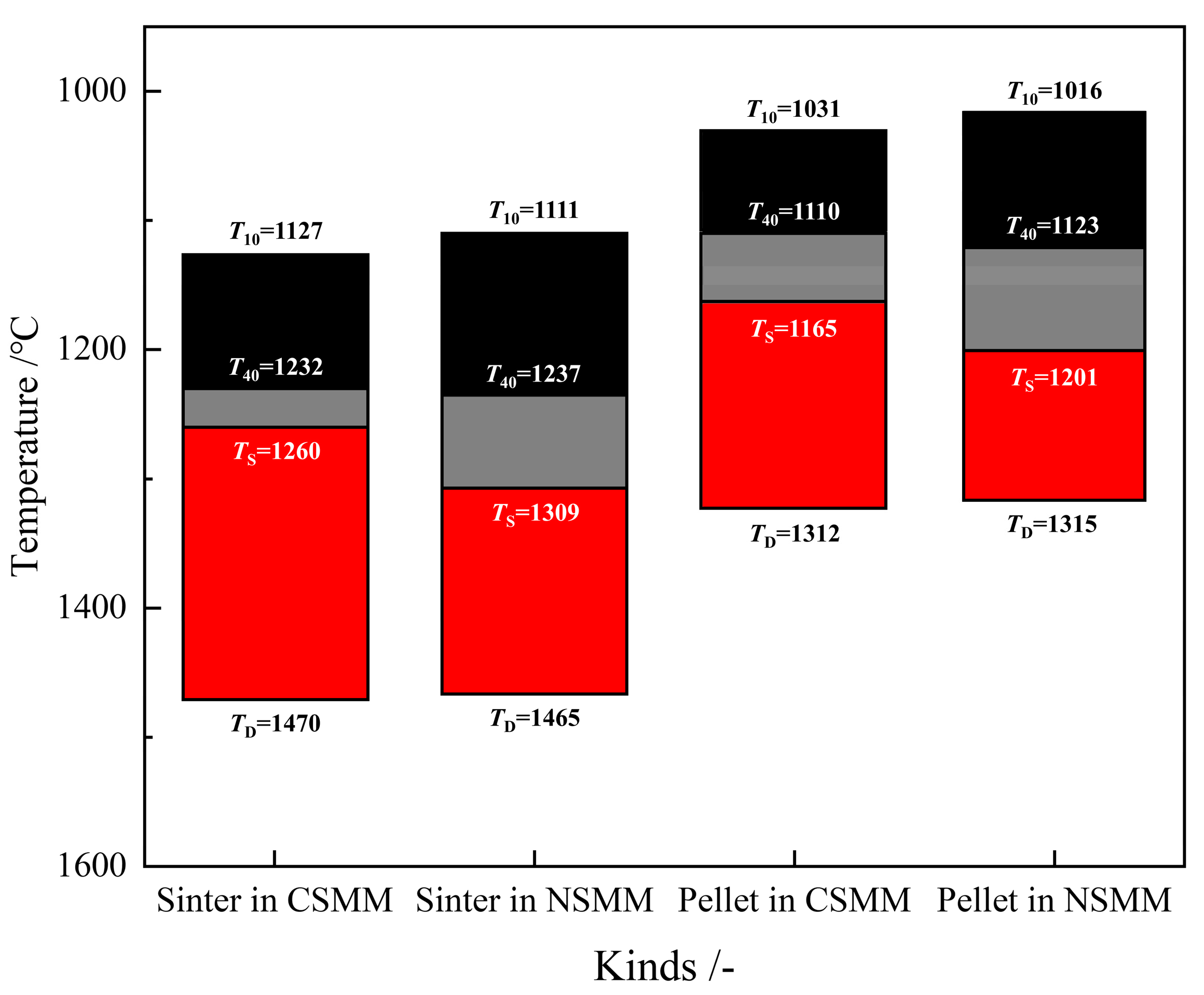
The softening–melting characteristic temperatures of iron-bearing materials using different softening–melting methods are illustrated in Figure 5. In the CSMM, the characteristic temperatures T10, T40, TS, and Td of the sinter are observed at 1127 °C, 1232 °C, 1260 °C, and 1470 °C, respectively. Conversely, in the NSMM, these characteristic temperatures are detected at 1111 °C, 1237 °C, 1309 °C, and 1465 °C, respectively. Notably, the characteristic temperatures (T40 and TS) of the sinter in the NSMM are 5 °C and 49 °C lower, respectively, than those in the CSMM. This difference can be attributed to the increased FeO content and the extension of reduction time from 800 °C to 1000 °C in the NSMM. With the higher FeO content, the melting point of the sinter is confirmed to rise, leading to a lower position of the cohesive zone and improved permeability in the NSMM compared to the CSMM.
Furthermore, in the CSMM, the characteristic temperatures T10, T40, TS, and Td of the pellet are observed at 1031 °C, 1110 °C, 1165 °C, and 1312 °C, respectively. Conversely, in the NSMM, these characteristic temperatures are observed at 1016 °C, 1132 °C, 1201 °C, and 1315 °C, respectively. Notably, the characteristic temperature (T40 and TS) of the pellet in the NSMM is 13 °C and 36 °C lower, respectively, than those in the CSMM. This difference can be attributed to the increased FeO content and the extension of reduction time from 800 °C to 1000 °C in the NSMM. With the higher FeO content, the melting point of the pellet is confirmed to rise, leading to a lower position of the cohesive zone and improved permeability in the NSMM compared to the CSMM.
Since the width of the melting temperature zone significantly influences permeability, a narrower zone indicates better permeability. Consequently, the iron-bearing materials in the NSMM exhibit superior permeability compared to those in the CSMM. This improvement significantly contributes to the consistency of blast furnace production practices.

4.2. Permeability

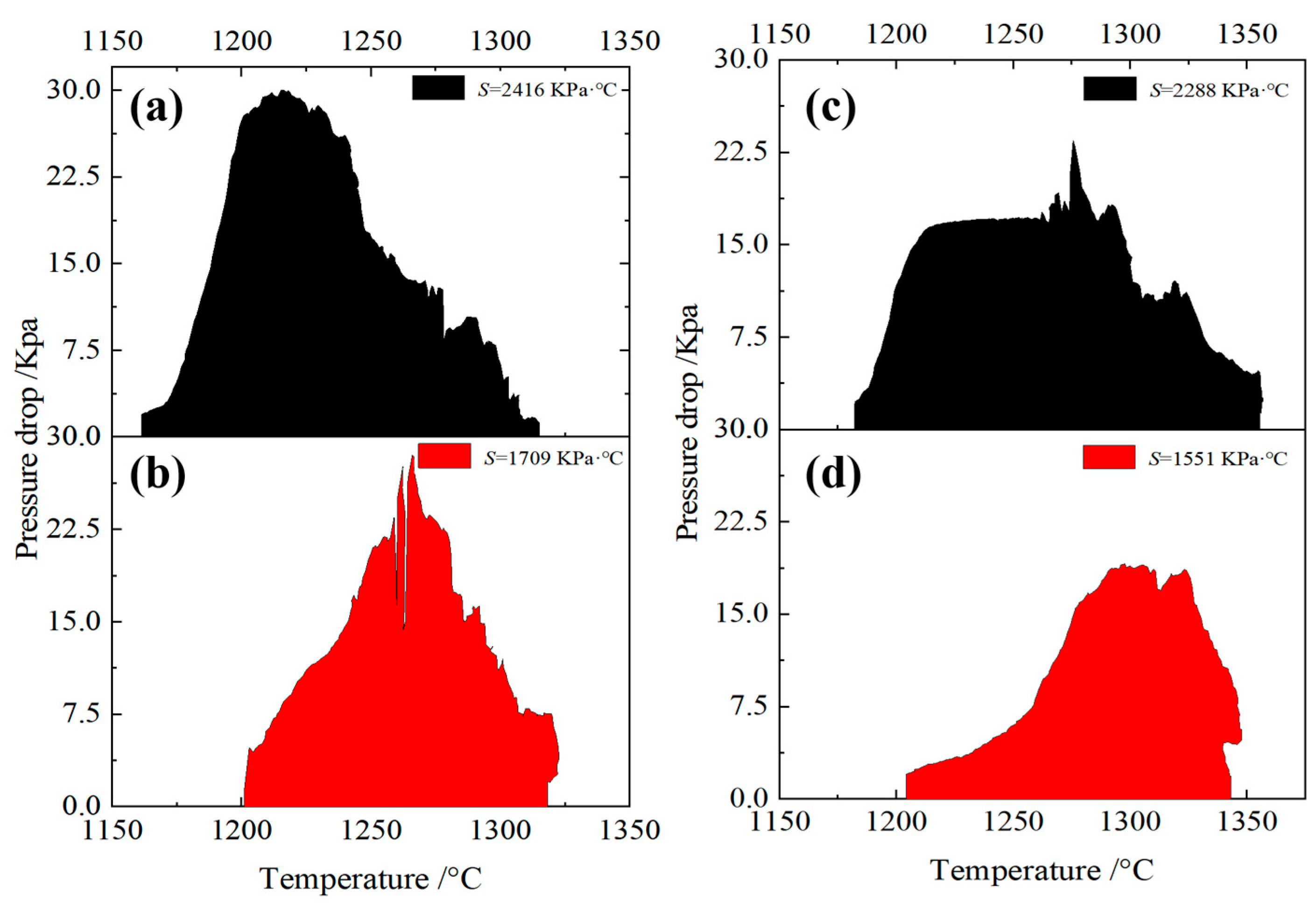
Permeability plays a significant role in the smooth operation of blast furnaces. To quantitatively evaluate the influence of different molten-droplet methods on permeability, a permeability index (S) was defined. Equation (1) is employed for calculating the S, where ∆P represents the pressure drop at a certain temperature between TS and Td in Pascals (Pa), and ∆P denotes the pressure drop at the melting start temperature in Pa.
S = T S T d Δ P m Δ P S d T
The permeability of iron-bearing materials under different molten-droplet methods is illustrated in Figure 6. Figure 6a and Figure 6b, respectively, depict sinter in the CSMM and NSMM. In the CSMM, the S and Pmax for sinter are confirmed at 2416 kPa·°C and 30.0 kPa, respectively, whereas in the NSMM, these values are confirmed at 1709 kPa·°C and 28.5 kPa, respectively. Clearly, the permeability of the sinter in the NSMM is better than that in the CSMM. Meanwhile, Figure 6c and Figure 6d, respectively, represent the pellet in the CSMM and NSMM. In the CSMM, the S and Pmax for the pellet are confirmed at 2288 kPa·°C and 23.5 kPa, respectively, whereas in NSMM, these values are confirmed at 1551 kPa·°C and 19.0 kPa, respectively. Once again, the permeability of the pellet in the NSMM is better than that in the CSMM. Consequently, this improvement significantly contributes to consistency with the operation of blast furnaces.

4.3. Dripping Behavior

The characteristic temperature (Td) indicates the ability of the molten ore to flow with a certain fluidity from the dripping zone to the deadman zone. The dripping characteristic of the iron-bearing materials is presented in Table 6. The Td of the sinter in the CSMM and NSMM is confirmed to be 1525 °C and 1520 °C, respectively, with neither showing the formation of dripping slag. Meanwhile, the Td of the pellet in the CSMM and NSMM is found to be 1348 °C and 1356 °C, respectively, with both showing the formation of dripping slag.

5. Conclusions

The softening–melting properties of iron-bearing materials play a crucial role in the reduction process of the lumpy zone, affecting the height, thickness, and shape of the cohesive zone, as well as gas permeability in the blast furnace. A novel testing method of softening–melting of iron-bearing materials was proposed, and the main findings can be summarized as follows.
  • Under the novel softening–melting testing method, the values of RIC1000 and RIN1000 of the sinter reached 25.41% and 59.58%, respectively. For the pellet, these values were 14.95% and 40.34%, respectively. Consequently, the reduction indices obtained in the novel method are consistent with the actual blast furnace.
  • Under the conventional softening–melting testing method, the reduction indices (RI) of the sinter at 700 °C, 800 °C, 900 °C, 1122 °C (T10), 1200 °C, 1218 °C (T40), and 1274 °C (TS) are 4.95%, 13.52%, 11.29%, 25.41%, 32.38%, 42.12%, 64.19%, and 69.55%, respectively. In contrast, under the novel softening–melting testing method, the reduction indices of the sinter at 700 °C, 800 °C, 900 °C, 1125 °C (T10), 1200 °C, 1292 °C (T40), and 1315 °C (TS) are 8.61%, 17.13%, 40.26%, 59.58%, 78.29%, 82.90%, 90.54%, and 96.81%, respectively. Furthermore, the reduction indices observed under actual blast furnace conditions at 1000 °C, 1100 °C, and 1300 °C are 49.1%, 99.3%, and 99.4%, respectively. One can conclude that the novel softening–melting method is consistent with the reduction conditions observed in an actual blast furnace. Consequently, reduction indices and the metallization degree of iron-bearing materials are consistent with those observed in an actual blast furnace.
Under the novel softening–melting testing method, the characteristic temperatures (T40 and TS) of the sinter increased by about 5 °C and 49 °C, respectively, compared to the conventional method. Additionally, the permeability index (S) of the sinter in the novel method is about 707 kPa· °C lower compared to the conventional method. Similarly, the characteristic temperatures (T40 and TS) of the pellet increased by about 13 °C and 36 °C, respectively, compared to the conventional method. Moreover, the permeability index (S) of the pellet in the novel method is about 737 kPa· °C lower compared to the conventional method. Clearly, the novel method results in higher softening–melting characteristic temperatures for iron-bearing materials compared to the traditional method, resulting in higher softening temperatures, lower melting temperatures, and improved permeability.

Author Contributions

Conceptualization, K.F.; methodology, X.J.; investigation, X.Z. and Q.W.; supervision, Q.G., H.Z. and F.S. All authors have read and agreed to the published version of the manuscript.

Funding

The National Natural Science Foundation of China (NSFC 52074074), China Baowu Low Carbon Metallurgy Innovation Foundation (BWLCF202303), and the National Key Research and Development Program of China (Grant No. 2021YFC2902401-1).

Data Availability Statement

The original contributions presented in the study are included in the article, further inquiries can be directed to the corresponding authors.

Acknowledgments

The financial support from the National Natural Science Foundation of China, China Baowu Low Carbon Metallurgy Innovation Foundation, and the National Key Research and Development Program of China is much appreciated.

Conflicts of Interest

Author Xin Zhang was employed by the company Ironmaking Department, Beijing Shougang Co., Ltd. The remaining authors declare that the research was conducted in the absence of any commercial or financial relationships that could be construed as a potential conflict of interest.

References

  1. Elices, M.; Guinea, G.V.; Gómez, J.; Planas, J. The cohesive zone model: Advantages, limitations and challenges. Eng. Fract. Mech. 2002, 69, 137–163. [Google Scholar] [CrossRef]
  2. Fan, X.; Jiao, K.; Zhang, J.; Wang, K.; Chang, Z. Phase Transformation of Cohesive Zone in a Water-quenched Blast Furnace. ISIJ Int. 2018, 58, 1775–1780. [Google Scholar] [CrossRef]
  3. Ueda, S.; Kon, T.; Kurosawa, H.; Natsui, S.; Ariyama, T.; Nogami, H. Influence of Shape of Cohesive Zone on Gas Flow and Permeability in the Blast Furnace Analyzed by DEM-CFD Model. ISIJ Int. 2015, 55, 1232–1236. [Google Scholar] [CrossRef]
  4. Chen, B.; Jiang, T.; Wen, J.; Yang, G.; Yu, T.; Zhu, F.; Hu, P. High-chromium vanadium–titanium magnetite all-pellet integrated burden optimization and softening–melting behavior based on flux pellets. Int. J. Min. Met. Mater. 2024, 31, 498–507. [Google Scholar] [CrossRef]
  5. Jiang, X.; Wu, G.; Li, G.; Shen, F. Study on improving the softening-melting properties of MgO-bearing iron ores. J. Northeast. Univ. (Nat. Sci.) 2013, 28, 365–368. [Google Scholar]
  6. Wang, G.; Kang, J.; Zhang, J.; Wang, Y.; Wang, Z.; Liu, Z.; Xu, C. Softening—Melting behavior of mixed burden based on low-magnesium sinter and fluxed pellets. Int. J. Min. Met. Mater. 2021, 28, 621–628. [Google Scholar] [CrossRef]
  7. Liu, X.; Honeyands, T.; Evans, G.; Zulli, P.; O’Dea, D. A review of high-temperature experimental techniques used to investigate the cohesive zone of the ironmaking blast furnace. Ironmak. Steelmak. 2018, 46, 953–967. [Google Scholar] [CrossRef]
  8. Zuo, G. Softening and Melting Characteristics of Self-fluxed Pellets with and without the Addition of BOF-slag to the Pellet Bed. ISIJ Int. 2000, 40, 1195–1202. [Google Scholar] [CrossRef]
  9. Kaushik, P. Mixed Burden Softening and Melting Phenomena. Ph.D. Thesis, Carnegie Mellon University, Pittsburgh, PA, USA, 2006. [Google Scholar]
  10. Kaushik, P.; Fruehan, R.J. Mixed burden softening and melting phenomena in blast furnace operation Part 1—X-ray observation of ferrous burden. Ironmak. Steelmak. 2006, 33, 507–519. [Google Scholar] [CrossRef]
  11. Kaushik, P.; Fruehan, R.J. Mixed burden softening and melting phenomena in blast furnace operation Part 2—Mechanism of softening and melting and impact on cohesive zone. Ironmak. Steelmak. 2006, 33, 520–528. [Google Scholar] [CrossRef]
  12. Kaushik, P.; Fruehan, R.J. Mixed burden softening and melting phenomena in blast furnace operation Part 3—Mechanism of burden interaction and melt exudation phenomenon. Ironmak. Steelmak. 2007, 34, 10–22. [Google Scholar] [CrossRef]
  13. Nogueira, P.F.; Fruehan, R.J. Blast furnace burden softening and melting phenomena: Part I. Pellet bulk interaction observation. Metall. Mater. Trans. B 2004, 35, 829–838. [Google Scholar] [CrossRef]
  14. Nogueira, P.F.; Fruehan, R.J. Blast furnace burden softening and melting phenomena: Part II. Evolution of the structure of the pellets. Metall. Mater. Trans. B 2005, 36, 583–590. [Google Scholar] [CrossRef]
  15. She, X.; Wang, J.; Liu, J.; Zhang, X.; Xue, Q. Increasing the Mixing Rate of Metalized Pellets in Blast Furnace Based on the High-temperature Interactivity of Iron Bearing Materials. ISIJ Int. 2014, 54, 2728–2736. [Google Scholar] [CrossRef]
  16. Kemppainen, A.; Ohno, K.; Iljana, M.; Mattila, O.; Paananen, T.; Heikkinen, E.; Maeda, T.; Kunitomo, K.; Fabritius, T. Softening Behaviors of Acid and Olivine Fluxed Iron Ore Pellets in the Cohesive Zone of a Blast Furnace. ISIJ Int. 2015, 55, 2039–2046. [Google Scholar] [CrossRef]
  17. Branescu, E.; Blajan, A.; Constantin, N. Experimental research on the characteristics of softening and melting of iron ores as significant factor of influence on gas permeability of blast furnace charge. IOP Conf. Ser. Mater. Sci. Eng. J. 2015, 85, 012006. [Google Scholar] [CrossRef]
  18. An, X.; Wang, J.; Lan, R.; Han, Y.; Xue, Q. Softening and Melting Behavior of Mixed Burden for Oxygen Blast Furnace. J. Iron. Steel. Res. Int. 2013, 20, 11–16. [Google Scholar] [CrossRef]
  19. Sternel, J.; Lahiri, A.K. Contraction and meltdown behaviour of olivine iron ore pellets under simulated blast furnace conditions. Ironmak. Steelmak. 1999, 26, 339–348. [Google Scholar] [CrossRef]
  20. Borinder, T. High temperature behaviour of some blast furnace pellets. P. 1. Scand. J. Metall. 1987, 16, 122–128. [Google Scholar]
  21. Shen, F.; Jiang, X.; Wu, G.; Wei, G.; Li, X.; Shen, Y. Proper MgO Addition in Blast Furnace Operation. ISIJ Int. 2006, 46, 65–69. [Google Scholar] [CrossRef]
  22. Gao, Q.J.; Wei, G.; Mu, L.; Du, G.; Shen, F.M. Experimental Study of Softening and Melting Properties on Indonesia Vanadium-Titanium Sinters. Adv. Mater. Res. 2011, 284–286, 1039–1043. [Google Scholar] [CrossRef]
  23. Guha, M.; Sinha, M. Tracking Softening-Melting Behaviour of Blast Furnace Burden. ISIJ Int. 2015, 55, 2033–2035. [Google Scholar] [CrossRef]
  24. Liu, J.; Cheng, G.; Liu, Z.; Chu, M.; Xue, X. Softening and melting properties of different burden structures containing high chromic vanadium titano-magnetite. Int. J. Miner. Process 2015, 142, 113–118. [Google Scholar] [CrossRef]
  25. Gustavsson, J.; Hahlin, P.; Jönsson, P. Meltdown behaviour of pellets reduced in a laboratory reduction furnace. Scand. J. Metall. 2003, 32, 100–112. [Google Scholar] [CrossRef]
  26. Shigaki, I.; Shirouchi, S.; Tokutake, K.; Hasegawa, N. Study and Improvement of Reduction and Melt-down Properties of Pellets. ISIJ Int. 1990, 30, 199–207. [Google Scholar] [CrossRef]
  27. Khaki, J.V.; Kashiwaya, Y.; Ishii, K. High temperature behaviour of selffluxed pellets during heating up reduction. Ironmak. Steelmak. 1994, 21, 56–63. [Google Scholar]
  28. Dawson, P. Determination of the high temperature properties of blast furnace burden materials. SEAISI Q. 1987, 16, 23–42. [Google Scholar]
  29. Liu, Z.; Chu, M.; Wang, H.; Zhao, W.; Xue, X. Effect of MgO content in sinter on the softening–melting behavior of mixed burden made from chromium-bearing vanadium–titanium magnetite. Int. J. Min. Met. Mater. 2016, 23, 25–32. [Google Scholar] [CrossRef]
  30. Geerdes, M.; Chaigneau, R.; Lingiardi, O. Modern Blast Furnace Ironmaking: An Introduction (2020), 4th ed.; IOS Press: Amsterdam, The Netherlands, 2020. [Google Scholar]
  31. Jiang, X. Fundamental Study on Reasonable Utilizating of Raw Material containing MgO in the Blast Furnace. Ph.D. Thesis, Northeastern University, Shenyang, China, 2008. [Google Scholar]
  32. Shen, Y.; Guo, B.; Chew, S.; Austin, P.; Yu, A. Three-Dimensional Modeling of Flow and Thermochemical Behavior in a Blast Furnace. Metall. Mater. Trans. B 2015, 46, 432–448. [Google Scholar] [CrossRef]
  33. Zhang, L.; Zhang, J.; Zuo, H.; Jiao, K. Temperature Field Distribution of a Dissected Blast Furnace. ISIJ Int. 2019, 59, 1027–1032. [Google Scholar] [CrossRef]
  34. Fan, X.; Zhang, J.; Jiao, K.; Zhang, J.; Wang, K. Distribution of harmful elements in dissected 125 m3 blast furnace. Can. Metall. Quart. 2019, 58, 400–409. [Google Scholar] [CrossRef]
  35. Zhang, J.; Luo, D.; Zeng, H.; Zuo, H.; Jiao, K. The Dissection Investigation of Blast Furnace; Metallurgical Industry Press: Beijing, China, 2019. [Google Scholar]
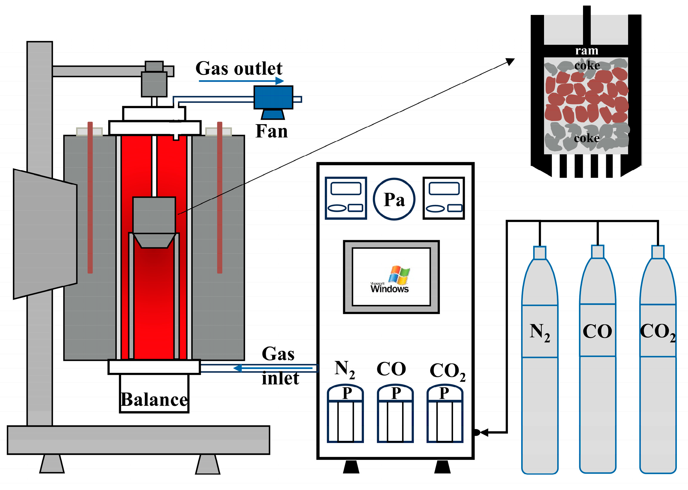
Figure 1. Schematic diagram of softening–melting method device (RSZ-03).
Minerals 14 01214 g001
Figure 2. Conventional softening–melting method (a) and novel softening–melting method (b) for S&M under load method.
Minerals 14 01214 g002
Figure 3. Schematic diagram of softening–melting property curve.
Minerals 14 01214 g003
Figure 4. Comparison of reduction index (a) and metallization degree (b) of sinter at various temperatures within the cohesive zone.
Minerals 14 01214 g004
Figure 5. Softening–melting characteristic temperatures of the iron-bearing materials with different softening–melting methods.
Minerals 14 01214 g005
Figure 6. Permeability of the iron-bearing materials under different softening–melting methods.
Minerals 14 01214 g006
Table 1. The chemical composition of iron-bearing materials (mass/%).
OresTFeFeOCaOSiO2MgOAl2O3
Sinter54.118.4812.385.831.082.06
Pellet61.495.681.388.530.750.96
Table 2. The proximate analysis of coke (mass/%).
Fixed CarbonAshVolatile MassMoisture
87.0712.290.630.01
Table 3. The indices for the S&M method.
SymbolSignificance
T10/°CThe beginning temperature of softening is defined as 10% shrinkage of iron-bearing materials
T40/°CThe softening temperature is defined as 40% shrinkage of iron-bearing materials
TS/°CThe melting temperature is defined as the pressure of the iron-bearing materials exceeding 2 kPa
Td/°CThe dripping temperature is defined as the temperature at which the first iron droplets begin to drip
(T40T10)/°CSoftening temperature zone
(TdTS)/°CMelting temperature zone
S /kPa·°CPermeability index, S = T S T d ( Δ P m Δ P s ) d T
Table 4. Comparison of reduction index (RI) under quenching (1000 °C) conditions with different methods.
SinterTFe/%FeO/%MFe/%RI/%
CSMM57.1938.944.4325.41
NSMM60.3133.6827.2059.58
PelletTFe/%FeO/%MFe/%RI/%
CSMM64.3136.060.2614.95
NSMM69.1267.8810.2840.34
Table 5. The reduction index of pellet in the conventional and novel S&M methods at different temperatures.
CSMM
/°C
TFe
/%
FeO
/%
MFe
/%
RI
/%
70063.7114.340.356.39
80063.5419.150.258.21
90063.6727.220.2511.48
100064.3136.060.2614.95
1070 (T10)66.5659.232.9027.44
1180 (TS)69.7854.5417.0244.66
NSMM
/°C
TFe
/%
FeO
/%
MFe
/%
RI
/%
70062.3719.300.298.49
80064.0639.020.1516.03
90067.6035.8420.0643.43
100069.1267.8810.2840.34
1081 (T10)74.3655.7728.7258.08
1204 (TS)73.6151.4431.4460.84
Table 6. Dripping characteristic of iron-bearing materials at Td.
OresMethodTdInitial Slag
SinterCSMM1525 °CNon-drop
SinterNSMM1520 °CNon-drop
PelletCSMM1348 °CDrop
PelletNSMM1356 °CDrop
Disclaimer/Publisher’s Note: The statements, opinions and data contained in all publications are solely those of the individual author(s) and contributor(s) and not of MDPI and/or the editor(s). MDPI and/or the editor(s) disclaim responsibility for any injury to people or property resulting from any ideas, methods, instructions or products referred to in the content.