Article

On the Initial Fabric of Naturally Occurring and Reconstituted Weakly Cemented Geomaterials

by
Mohd Ilyas Bhat
,
Bhupendra Chand
and
Tejas Gorur Murthy
*
Department of Civil Engineering, Indian Institute of Science, Bangalore 560012, India
*
Author to whom correspondence should be addressed.
These authors contributed equally to this work.
Minerals 2024, 14(10), 1000; https://doi.org/10.3390/min14101000
Submission received: 29 August 2024 / Revised: 27 September 2024 / Accepted: 28 September 2024 / Published: 30 September 2024

Abstract

:
The understanding of naturally occurring materials such as clay, sand, hard and soft rocks under a common theoretical framework has been a topic of persistent research interest. Over the past few decades, various sample reconstitution techniques have been developed in the literature to mimic in situ conditions, and to parse carefully the influence of various components in a cohesive-frictional geomaterial such that their behavior can be folded into the broad ambit of a continuum mechanics framework. The initial fabric of natural rock specimens is compared with reconstituted cemented sand samples using X-ray computed tomography (XRCT) scans. The efficacy of laboratory reconstitution techniques in replicating the initial microstructural features of natural rocks is evaluated here. Additionally, discrete element method (DEM) protocols which are often employed in generating cohesive granular ensembles are employed here and compared against the naturally occurring and artificially reconstituted fabric. A significant difference is observed in the grain boundaries of reconstituted and naturally occurring rocks. Additionally, the arrangement of particles, the orientation of grain contacts, and their coordination number are examined to assess the efficacy of laboratory-reconstituted specimens at micro-length scale.

1. Introduction

Structured soils, artificially cemented sands, and weak or soft rocks form an important intermediate class of geomaterials. [1,2]. In such geomaterials, the presence of cohesive bonds between the particles significantly enhances the strength of the ensemble [3]. The strength of loose sand deposits is often enhanced artificially by the introduction of a cementing agent such as Portland cement (OPC) [4], calcite [5], gypsum [6], clay [7,8], etc. Structured sands and soft rocks are also formed in nature by various geological processes such as erosion, sedimentation, welding, lithification, etc. [1]. Sedimentary rocks are an important class of naturally bonded geomaterials [9] which often exhibit characteristics in between those of classical rocks and dense sand. A very short note on the formation of sedimentary rocks in nature is presented in the ensuing.
Sedimentary or soft rocks are formed from the accumulation of rock fragments and organic materials on the earth’s surface or in oceans [10]. An understanding of the mechanical behavior of sedimentary rocks is crucial, given that it is frequently encountered in various infrastructure [11], mining [12], petroleum, and natural gas industry operations [13]. The response of sedimentary rocks under a range of boundary conditions is a strong function of the fabric. The fabric of a geomaterial is defined as the distribution of its particle sizes, particle orientation, contact orientation, and bonding characteristics [14,15,16,17], which are a consequence of the physical and chemical processes leading to its formation [18]. The formation of sedimentary rocks involves several processes, starting with the weathering and erosion of pre-existing rocks. The resulting sediments are transported by gravity, wind, water, and ice to new locations, where they accumulate in layers [19]. The weight of these layers consolidates the sediments, reducing the pore space by expelling water or air. In some conditions, the minerals and chemicals on the Earth’s surface precipitate from water, binding the sediment particles and turning them into rock. The binding of sediment particles and their fusion into a rock can occur even in the absence of water through other processes, such as local welding at contacts of the sediments. This binding process is known as lithification [20].
Various physical models [21,22] and elemental laboratory tests [23,24,25,26] on undisturbed samples are often employed to study the ensemble level or macroscopic behavior of naturally occurring sedimentary rocks. There is a large suite of constitutive models developed using the framework of continuum mechanics for different classes of sedimentary rocks to predict their behavior [27,28,29,30]. This suite of constitutive models often employ a state of “complete destructured material” as a baseline for modeling the mechanical response of soft rocks [31,32,33,34]. For example, many constitutive models of cemented sands employ the notion of the presence of interparticle cementation as an additional confining pressure over the parent sand (i.e., the complete destructured material) [33]. In this context, the laboratory tests using reconstituted soft rocks are critical [33,35,36]. The predominant objective in reconstituting elemental sample specimens in the laboratory is the accurate control of important variables such as porosity, degree and type of cementation, and curing conditions, all of which facilitate the parsing of these variables to study their individual effects. Additionally, perhaps the most important need for reconstitution is to replicate naturally occurring fabric in the laboratory. Lastly, as the extraction of undisturbed samples is expensive and tedious, reconstituted samples provide an important alternative in research. Hence, experimental studies using reconstituted structured soils have contributed in no small measure to developing a comprehensive understanding of the mechanical behavior of soft rocks [37,38,39].
A non-exhaustive list of commonly employed sample reconstitution methods in laboratory studies on bonded geomaterials are enumerated below:
(a) Wet tamping method: In this method sand, a cementing agent such as OPC, gypsum, clay, etc., and water are mixed together to obtain a uniform mixture or paste at the required cement and water content. The mixture is then filled in a lubricated mold in layers, followed by the compaction of each layer. The number of layers and compaction energy depends on the desired porosity and the considerations of homogeneity of the sample [40,41].
(b) Dry tamping method: In this method, a dry mix of sand and cementing agent such as OPC, gypsum, clay, etc. is poured into a mold, followed by its compaction. Once the dry mixture layers are compacted in a membrane, deaired water is percolated through the sample to initiate hydration. This method provides the option of curing cemented sand samples at controlled confining stresses, which is expected to mimic the geological conditions of lithification in weak rocks [42].
(c) Calcite precipitation methods: Calcite is also commonly present as a cementing agent in naturally formed bonded sands and weak rocks. Chemical reactions that precipitate calcium are used to create calcium carbonate bonds between particles in an ensemble. The granular matrix is usually created by air pluviation or water pluviation. Calcite precipitation is induced by percolating supersaturated calcite solutions or calcite cement through the sand matrix. Aerobically cultivated bacteria with highly active urease enzyme can also be introduced into soil, which releases a urease enzyme that catalyzes the hydrolysis of urea to produce ammonium and carbonate ions that precipitate and bond the particles [5,43].
All these different reconstitution techniques impart a characteristic initial fabric or structure which may not necessarily reproduce the fabric of naturally bonded geomaterials (that is, soft rocks formed by geological processes of transportation, sedimentation, welding, chemical changes, and physical conditions of stress and temperature) [1,2,44,45,46].
The different reconstitution techniques enumerated above result in very different initial fabrics in laboratory samples and consequently give rise to differences in their mechanical behavior [15,17,47]. While the effects of sample reconstitution methods on the stress–strain behavior of cemented sands has been extensively explored [5,40,41,42], quantitative comparisons of the fabric of naturally occurring soft rocks and reconstituted specimens have been very few and far between.
The objective of our study is to investigate and compare the fabric or structure of natural soft rock and laboratory reconstituted artificial rock. We aim to quantify the fabric of the both samples and compare them to estimate the efficacy of the laboratory reconstitution methods to replicate natural rock fabric. With the advent and increasing availability of 3D X-ray imaging technology in recent decades, X-ray computed micro-tomography (XRCT) provides an efficient tool to obtain high-resolution 3D images of granular materials [48,49]. In this study, we aim to employ CT imaging along with image analysis to digitally reconstruct particles and extract the contact geometry in a naturally occurring weak sandstone and in a laboratory reconstituted weakly cemented sand samples. The fabric of these both samples will be quantified using a series of microstructural parameters—viz. coordination number distribution, fabric tensor and fabric anisotropy parameters [14,15,16,17]. After the quantification and comparison of the initial fabric of natural weak sandstone and reconstituted rock samples, we employ commonly adopted discrete element method (DEM) [50] sample generation protocols to generate cemented sand samples to explore the possible factors during the deposition and compaction of sediments that are consequential in imparting the characteristic fabric to the weak rocks.

2. Materials and Methods
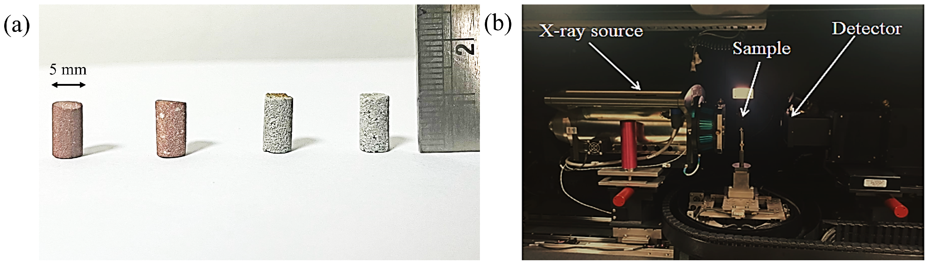
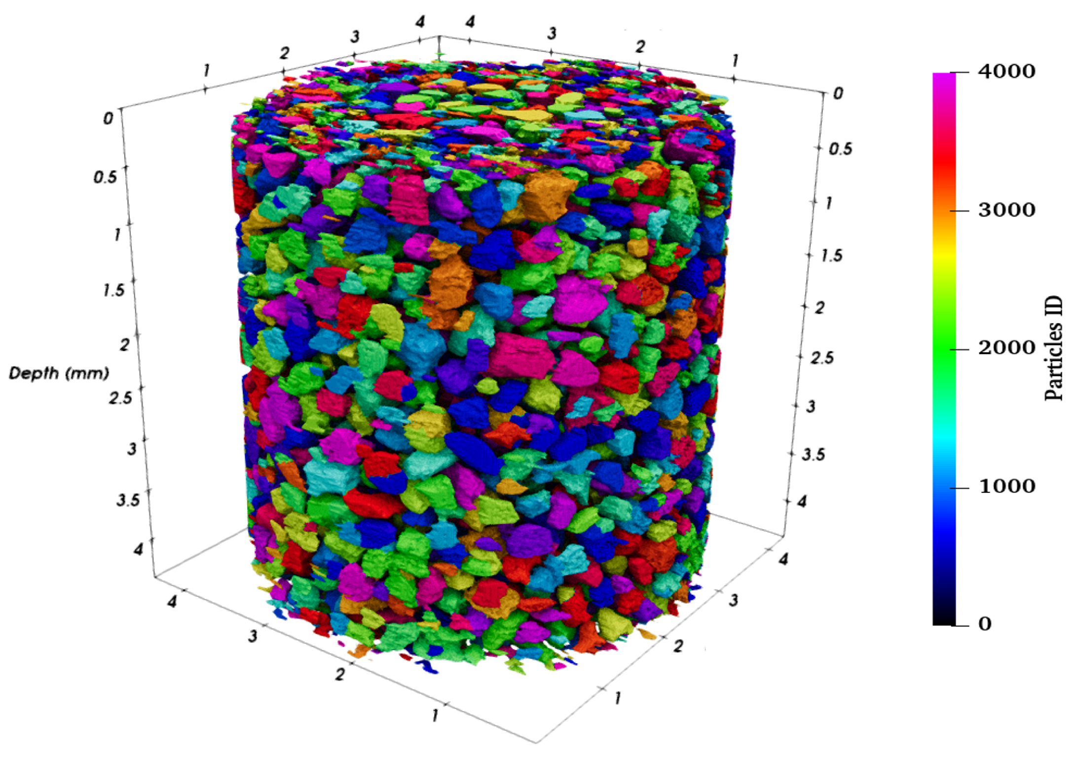
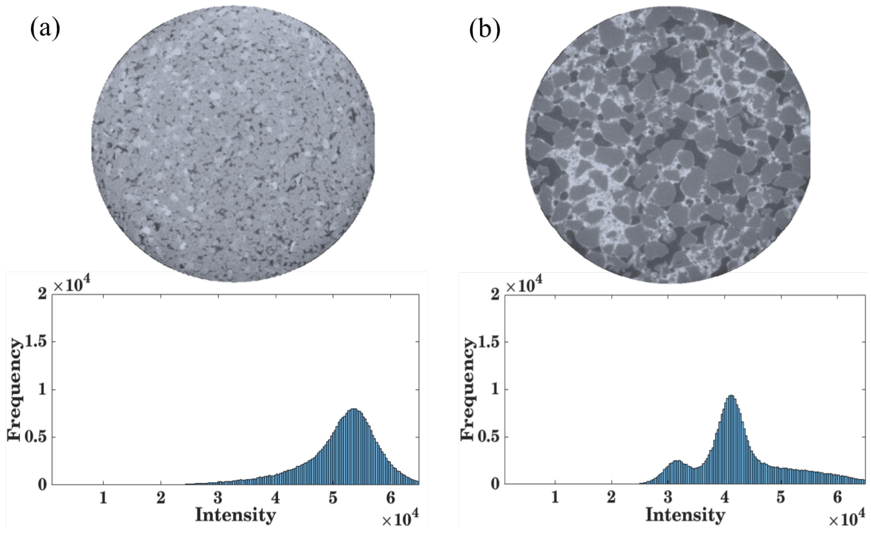
2.1. Experiments

In this study, two types of samples were scanned inside an X-ray computed tomograph. The XRCT instrument with model name ZEISS XRadia context micro CT is manufactured by ZEISS Microscopy in Oberkochen, Germany The first sample was a naturally occurring sandstone (NR) obtained from the Shivalik range of the Himalayan mountains. The second sample was an artificial weak rock (AR) created via laboratory reconstitution using sand and ordinary Portland cement. The sand grains had a size of 300 ± 50 μ m, and the wet tamping method was employed to prepare the specimen. A volumetric cement content of 8% by weight was used to create a void-bound specimen [51], ensuring that the strength of the natural and artificial samples was comparable. The wet sample paste was doped with a small amount of barium sulfate (an X-ray contrasting agent) as a contrasting agent to visualize the cement bonds. The artificially reconstituted sample was scanned after 28 days of curing. All the specimens were cylindrical, with a diameter of 5 mm and a height of 10 mm. The image of the samples and the X-ray CT setup is shown in Figure 1.
Over 1000 scans were captured from each specimen, and the entire ensemble was reconstructed by stitching the images together using MATLAB (R2023a version). All scans were captured at an energy level of 140 keV and a resolution of 7 μ m. The Otsu thresholding technique was used to binarize the 3D ensemble [52], which was then segmented into particles and voids using Morse-Gram software (see: https://bitbucket.org/vgl_iisc/morsegram, accessed on 29 August 2024) [53]. This algorithm utilizes the topological features of the images and assigns a unique ID to each individual particle. The labeled image of the AR specimen is shown in Figure 2, where the colors represent the IDs of the particles.

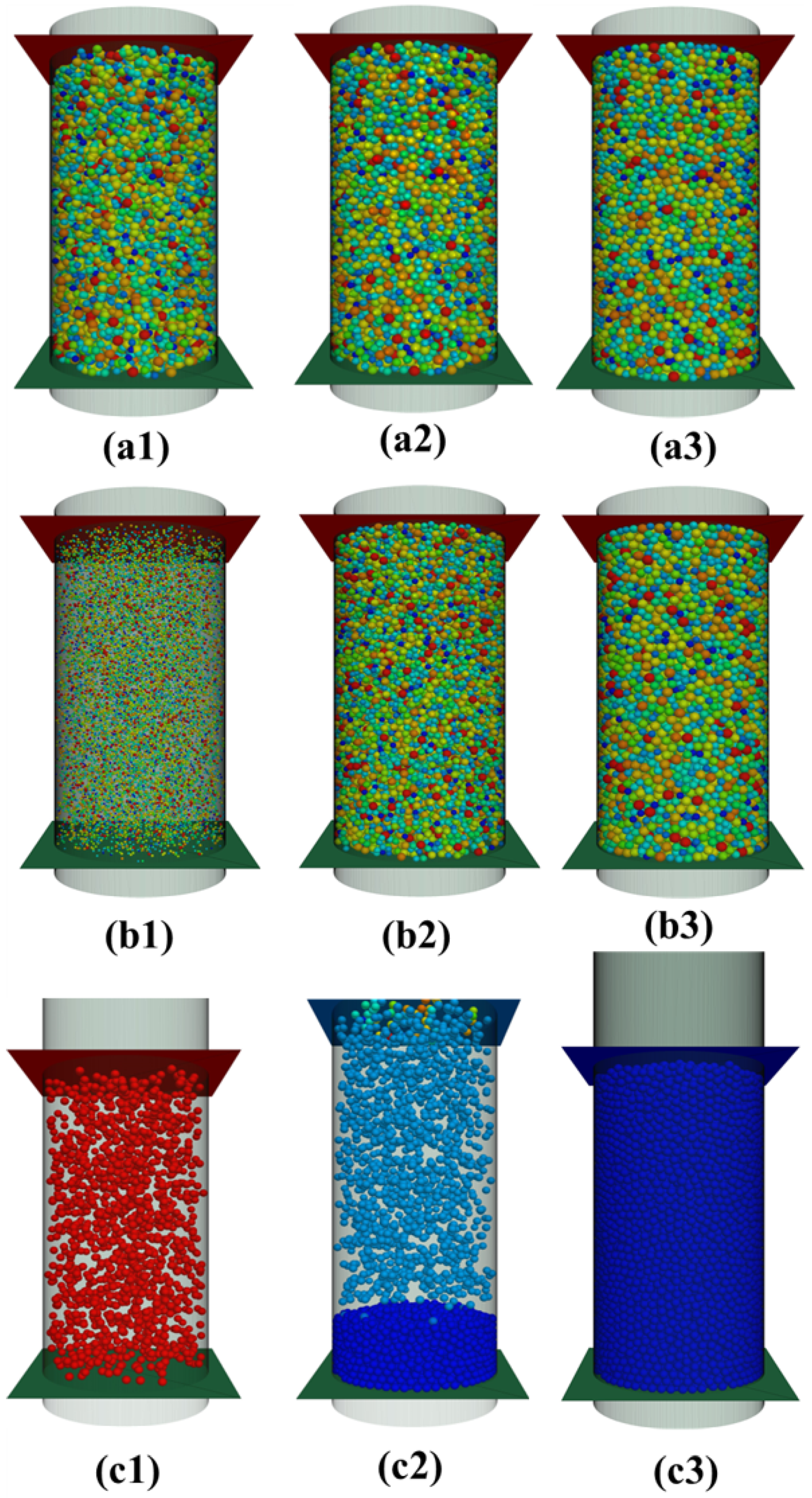
2.2. DEM Simulations

The discrete element technique models the mechanics of particulate materials by the time-step solution of Newton’s laws of motion and is efficient in capturing interparticle interactions [50,54]. Analogous to the variety of reconstitution protocols employed in laboratory, DEM simulations of granular materials also employ a range of sample generation protocols to generate particle ensembles [55]. Each sample generation protocol is invented with a specific focus—that is, to simulate samples with specific attributes, for example, protocols that generate homogeneous samples, or protocols that generate a specific initial fabric or a specific target porosity, etc. Three of the commonly employed methods of sample generation in DEM simulations include the following.
(a) Overlapped generation method (random number approach): This is arguably one of the simplest ensemble generation methods employed in DEM. The particles of a given size distribution are generated at random positions inside a walled container at the desired porosity [56,57,58]. As the particles are generated randomly, they have large unrealistic overlaps, which are even comparable to the particle diameter. In order to bring the particle overlaps within acceptable limits, the simulation is run for a small number of cycles, small enough to ensure the particle displacements to be significantly less than the particle diameter. After the given number of time cycles are completed, all the particle velocities are again set to zero to dissipate the kinetic energy in the system. By repeating this process of small time cycling and removing particle velocities multiple times, the high initial elastic energy of the overlapped particles is converted into kinetic energy and immediately expelled from the system (see Figure 3a1,a2,a3).
(b) Particle expansion method (radius expansion): The particles of the required size distribution are generated at much smaller radii in a wall-enclosed space and in the absence of gravity. The radii of the particles are then increased gradually at very low values of friction coefficients. Once the radii of the particles are increased to the target size, the values of friction coefficients are increased, and the ensemble is achieved at the desired porosity [59,60] (see Figure 3b1,b2,b3).
(c) Undercompaction method: The sample is generated in multiple layers, and each layer is compacted to a desired porosity before the subsequent layer. After the generation of particles for each layer in a cylindrical container, the layer is compressed by a moving rigid wall to a calculated height. Once the layer is compacted, the sample is equilibrated, and the same procedure is followed for the next layer and eventually the complete sample. This method is a DEM equivalent of wet and dry undercompaction methods used in laboratory sample reconstitution [56,61] (see Figure 3c1,c2,c3).
In all DEM simulations, a linear frictional contact model with rolling friction component is employed at all the particle–particle and particle–wall contacts. The diameter of the specimen is maintained at 15 times the average particle diameter. The spherical particle radii are normally distributed within a normalized standard deviation of 0.15. The values of contact model parameters are adopted from the proposed values in the literature for quartz sand particles [4,49,62,63]. The DEM model parameters are listed in Table 1.

3. Results

The scanned X-ray CT cross-sectional images of the ensemble are stitched together to reconstruct the 3D volume, which is further segmented in the MorseGram software [53]. The MorseGram segmentation scheme works on the principle of Morse–Smale theory and uses topological features of the image for segmentation of the discrete objects. The labeled 3D image of the artificial rock ensemble is shown in Figure 2, where each color represents the unique identification number of the particle. After the segmentation, the characteristic features of the particles like their volume, surface area, centroid, equivalent radius, eigenvalues, eigenvectors, etc., are determined, which are used for micro-scale quantification of the fabric. Figure 4a,b illustrate cross-sections of both (natural sandstone) NR and (artificially cemented) AR samples. In the AR sample, regions corresponding to particles, cementation, and void spaces are clearly distinguishable, whereas such distinction is not evident in the NR sample. This is apparent from the histograms of intensities which have been presented with the cross-sectional images in Figure 4a,b.
The AR sample displays two distinct peaks corresponding to voids and solid phases (particles and cementation), whereas the NR sample shows only one peak. The uniform intensity across the NR sample results from the fusion of natural sediment particles, when they are subjected to extremely high pressure and temperature.
The effect of sample generation methods or protocols on the initial structure and fabric of the ensemble is more accentuated in the DEM samples. One quantitative parameter to evaluate the contact fabric in an ensemble is the contact fabric tensor [64,65]. Mathematically, it is calculated as the average dyadic product tensor of the contact unit vectors, given by Equation (1):
F c = 1 N c i = 1 N c n c i n c i
where N c is the number of contacts in the ensemble, and n c i is the contact unit vector of the ith contact. The contact fabric tensors for three ensembles generated by the three DEM sample generation protocols and for the AR sample are as follows:
Overlap   generation   method : 0.331 0.00341 0.00025 0.00341 0.331 0.000333 0.00025 0.000333 0.338
Particle   expansion   method : 0.331 0.000574 0.00025 0.000574 0.331 0.000139 0.000149 0.000139 0.338
Undercompaction   method : 0.32 0.0007 0.00056 0.0007 0.32 0.00038 0.00056 0.00038 0.36
Artificial   rock   specimen : 0.388 0.006 0.004 0.006 0.332 0.002 0.004 0.002 0.281
The difference between the major and the minor components of the fabric tensor is a measure of the contact fabric anisotropy in an ensemble [57,66,67]. The overlapped and particle expansion methods are usually employed to generate homogeneous and isotropic ensembles, which is observed in their resultant fabric tensors. All the diagonal components of their corresponding fabric tensors are nearly equal to 0.33. The contact fabric tensor of the sample generated by the undercompaction method shows significant anisotropy. Instead of equal diagonal components of 0.33, the diagonal components of the fabric tensor for the sample generated by undercompaction method are 0.32, 0.32, and 0.36, which indicates significant contact anisotropy in the ensemble.
The distribution of the angle which the contact normal directions make with the vertical axis for the three DEM samples is presented in Figure 5a.
For the overlapped and the particle expansion sample generation protocols, the contact angle with vertical axis’ distributions are identical. For the undercompaction method, the distribution shows the characteristic dip in frequency at an angle of 75 deg. with the vertical. Similarly, the coordination number (CN) distribution for the three ensembles exhibits a similar trend as shown in Figure 5b. The CN distribution is identical for the overlapped and the expansion generation method but is different in the case of the undercompaction generation method. The average coordination number of ensembles generated by the overlapped, expansion, and undercompaction methods are 5.45, 5.41, and 5.31, respectively. The larger coordination numbers occur less frequently in the undercompaction generation method as compared to the other two methods.

4. Discussion

In this study, we visualize the three-dimensional microstructure of the rock specimens using high-resolution XRCT images.
The formation of sedimentary rocks under extreme conditions of pressure and temperature makes the fragments of weathered rocks lose their parent-fragmented feature and form a complex structure that is difficult to replicate either in the lab or using DEM. The average density of the rock specimens used in this study was 2.2 g/cc (grams per cubic centimeter), and the artificial rock (AR) samples were prepared to match this target density. It should be noted here that calcite precipitation and dry tamping techniques were prepared exactly to the required density of 2.2 g/cc, and the maximum density achieved using the wet tamping method was 1.90 g/cc, which is significantly lower than the natural rock (NR) sample density. The high attenuation density of rock specimens also rendered the imaging process quite challenging. Thus, a very high energy of 140 keV was used in the experiment to capture the CT images.
The accuracy of the segmentation relies on image binarization, which distinguishes grains and cementation from the background voids in the ensemble. Figure 4 shows the cross-section of the natural and artificial rock specimens. The cemented sand specimen clearly distinguishes the cement, grain, and void phases. In Figure 4b, the dark regions represent void spaces, while the bright regions indicate cementation. The intensity histogram provides two distinct peaks, suggesting that the grain and void spaces have different attenuation and can be distinguished from each other. Similar features are observed in the scans of artificial cemented sand specimens available in the literature [68,69,70], irrespective of their resolution.
The contact fabric tensor for the artificial rock sample indicates that most grain contacts are oriented along the x-direction. On the other hand, natural rock scans have no distinction among the three phases, which makes it difficult for the post analysis. Additionally, a limestone sample was scanned during the experiments. However, due to its high density and fusion of constitutive particles, the specimen obstructs a major portion of the X-ray transmission, appearing as a solid block in the images.
As shown in the results from DEM samples, with the presence of gravity, the process of the deposition and compaction does have non-trivial imprints on the ensemble fabric, even in the case of spherical particles. The process of sample generation significantly determines the properties of the contact network, contact density, and particle and contact orientations in an ensemble. Given the variability of constituent sediment particle morphologies and the processes involved in the lithification of sandstone and other sedimentary rocks, a wide range of microstructural features in these materials can be expected.
The stark contrast in the bonding features observed in the AR and NR samples is a clear consequence of the limitations of laboratory reconstitution methods in replicating the structural features of natural sedimentary rocks. The microstructral features present in natural weak rocks owing to the time scale, presence of chemical agents, range of temperature, and pressure encountered during the lithificaton of sedimentary rocks cannot be simulated during lab reconstitution, and its absence is apparent in the difference in structure in the AR and NR samples, particularly in the particle fusion induced bonding in the natural weak rocks, which needs to be carefully studied to compare its micromechanics with cement bridge bonds formed in artificial bonded samples. While the artificially bonded materials can have a contact-bound, void-bound, or matrix-bound bonding structure with a proper delineation possible between the bonding agent and the granular particles, the fusion in natural rocks shows an interpenetration and homogenization at the contact zones between the grains.
The interpenetration of the grains as observed inside the CT for a natural sandstone sample shows two predominant phases—the undivided solid phase and the pore phase. Hence, the structure of naturally occurring soft rocks in general can be described as a two-phase material with a solid phase devoid of any clear separation or any grain boundaries present alongside a tortuous pore network. A reconstitution protocol to obtain a two phase porous media is perhaps better suited to study the behavior of natural soft rocks like weak sand stones. Laboratory reconstituted cemented sand specimens (AR) show a very clear composite structure with multiple distinguishable phases (of the parent grain, the interparticle cohesion, and the pore space). Such a structure is perfectly poised to replicate natural specimen density and strength, but is not suitable to recreate fabric and microstructures.
The current study was restricted to the initial fabric and intact samples, a critical aspect of the mechanical response of soft rocks is the accumulating damage and the presence of multiple operative mechanisms that include fracture, pore collapse, and plasticity during deformation. The reconstitution of specimens should also consider these microstructural aspects of mechanical response in addition to matching the ensemble response.

5. Conclusions

This paper explores the efficacy of the common laboratory sample reconstitution techniques to replicate the fabric and structure of the naturally occurring weak rocks. Although the reconstituted samples prepared under controlled conditions offer valuable macroscopic insights into the destructuring process of the natural rocks, the XRCT analysis suggests that the initial fabric of the artificial samples differs drastically from that of the natural ones. The difference in the structure of the natural and artificial rock is qualitatively different with no discernible grain boundaries or bonding bridges present in the natural rock sample. Even in the DEM samples, the orientation of particle’s contacts depends on the preparation technique used. While the overlap generation and particle expansion methods produce isotropic ensembles, samples created through the undercompaction method exhibit significant anisotropy. These DEM results highlight the effect of the presence of factors such as gravity, compaction and layering on the structure of geomaterials. These factors should be taken into account while attempting to replicate the mechanical response of the natural rock with the artificially cemented sand specimens in laboratory experiments.

Author Contributions

Formal analysis, M.I.B.; Investigation, M.I.B. and B.C.; Writing—original draft, B.C.; Writing—review and editing, T.G.M. All authors have read and agreed to the published version of the manuscript.

Funding

The authors would like to thank the SERB for their generous SRG grant that has made this research possible.

Data Availability Statement

Data are contained within the article.

Conflicts of Interest

The authors declare no conflict of interest.

References

  1. Leroueil, S.; Vaughan, P. The general and congruent effects of structure in natural soils and weak rocks. Géotechnique 1990, 40, 467–488. [Google Scholar] [CrossRef]
  2. Gens, A. Conceptual bases for a constitutive model for bonded soils and weak rocks. In Proceedings of the Geotechnical Engineering of Hard Soils-Soft Rocks: Proceedings of International Symposium under the auspices of the ISSMFE, Athens, Greece, 20–23 September 1993; pp. 485–494. [Google Scholar]
  3. Cuccovillo, T.; Coop, M. On the mechanics of structured sands. Géotechnique 1999, 49, 741–760. [Google Scholar] [CrossRef]
  4. Wang, Y.H.; Leung, S.C. A particulate-scale investigation of cemented sand behavior. Can. Geotech. J. 2008, 45, 29–44. [Google Scholar] [CrossRef]
  5. Cheng, L.; Cord-Ruwisch, R.; Shahin, M.A. Cementation of sand soil by microbially induced calcite precipitation at various degrees of saturation. Can. Geotech. J. 2013, 50, 81–90. [Google Scholar] [CrossRef]
  6. Haeri, S.M.; Hamidi, A.; Tabatabaee, N. The effect of gypsum cementation on the mechanical behavior of gravely sands. Geotech. Test. J. 2005, 28, 380–390. [Google Scholar] [CrossRef]
  7. Jawad, T.; Baqir, A. Improvement of sandy soil properties by using bentonite. Kufa J. Eng. 2009, 1, 29–39. [Google Scholar] [CrossRef]
  8. Najjar, S.; Yaghi, K.; Adwan, M.; Jaoude, A. Drained shear strength of compacted sand with clayey fines. Int. J. Geotech. Eng. 2015, 9, 513–520. [Google Scholar] [CrossRef]
  9. Alvarado, G.; COOP, M.R.; Willson, S. On the role of bond breakage due to unloading in the behaviour of weak sandstones. Géotechnique 2012, 62, 303–316. [Google Scholar] [CrossRef]
  10. Mackenzie, F.T.; Garrels, R. Evolution of Sedimentary Rocks; Norton: New York, NY, USA, 1971. [Google Scholar]
  11. Jeng, F.S.; Weng, M.C.; Huang, T.H.; Lin, M.L. Deformational characteristics of weak sandstone and impact to tunnel deformation. Tunn. Undergr. Space Technol. 2002, 17, 263–274. [Google Scholar] [CrossRef]
  12. Maynard, J.B. Geochemistry of Sedimentary Ore Deposits; Springer Science & Business Media: Berlin/Heidelberg, Germany, 2012. [Google Scholar]
  13. Hunt, J.M. Distribution of hydrocarbons in sedimentary rocks. Geochim. Cosmochim. Acta 1961, 22, 37–49. [Google Scholar] [CrossRef]
  14. Quinteros, V.S.; Carraro, J.A.H. The initial fabric of undisturbed and reconstituted fluvial sand. Géotechnique 2023, 73, 1–15. [Google Scholar] [CrossRef]
  15. Gao, Z.; Zhao, J. Constitutive modeling of artificially cemented sand by considering fabric anisotropy. Comput. Geotech. 2012, 41, 57–69. [Google Scholar] [CrossRef]
  16. Singh, S.; Miers, J.; Saldana, C.; Murthy, T. Quantification of fabric in cemented granular materials. Comput. Geotech. 2020, 125, 103644. [Google Scholar] [CrossRef]
  17. Alvarado, G.; Lui, N.; Coop, M.R. Effect of fabric on the behaviour of reservoir sandstones. Can. Geotech. J. 2012, 49, 1036–1051. [Google Scholar] [CrossRef]
  18. Brewer, R.; Sleeman, J. Soil structure and fabric: Their definition and description. J. Soil Sci. 1960, 11, 172–185. [Google Scholar] [CrossRef]
  19. Tucker, M.E.; Jones, S.J. Sedimentary Petrology; John Wiley & Sons: Hoboken, NJ, USA, 2023. [Google Scholar]
  20. Shrock, R.R. A classification of sedimentary rocks. J. Geol. 1948, 56, 118–129. [Google Scholar] [CrossRef]
  21. Zhang, B.; Sun, X.; Yang, K.; Guo, P.; Tao, Z. Model test study on large deformation mechanism of thin-bedded metamorphic sandstone tunnel. Bull. Eng. Geol. Environ. 2022, 81, 436. [Google Scholar] [CrossRef]
  22. Liu, X.; Chen, H.; Liu, K.; He, C. Model test and stress distribution law of unsymmetrical loading tunnel in bedding rock mass. Arab. J. Geosci. 2017, 10, 1–11. [Google Scholar] [CrossRef]
  23. Zhu, Q.; Li, D.; Han, Z.; Li, X.; Zhou, Z. Mechanical properties and fracture evolution of sandstone specimens containing different inclusions under uniaxial compression. Int. J. Rock Mech. Min. Sci. 2019, 115, 33–47. [Google Scholar] [CrossRef]
  24. Fakhimi, A.; Hemami, B. Rock uniaxial compression test and axial splitting. Procedia Eng. 2017, 191, 623–630. [Google Scholar] [CrossRef]
  25. Zong, Y.; Han, L.; Wei, J.; Wen, S. Mechanical and damage evolution properties of sandstone under triaxial compression. Int. J. Min. Sci. Technol. 2016, 26, 601–607. [Google Scholar] [CrossRef]
  26. Corfdir, A.; Sulem, J. Comparison of extension and compression triaxial tests for dense sand and sandstone. Acta Geotech. 2008, 3, 241–246. [Google Scholar] [CrossRef]
  27. Tsesarsky, M.; Gal, E.; Machlav, E. 3-D global–local finite element analysis of shallow underground caverns in soft sedimentary rock. Int. J. Rock Mech. Min. Sci. 2013, 57, 89–99. [Google Scholar] [CrossRef]
  28. Fazio, N.L.; Perrotti, M.; Lollino, P.; Parise, M.; Vattano, M.; Madonia, G.; Di Maggio, C. A three-dimensional back-analysis of the collapse of an underground cavity in soft rocks. Eng. Geol. 2017, 228, 301–311. [Google Scholar] [CrossRef]
  29. Adachi, T.; Oka, F. An elasto-plastic constitutive model for soft rock with strain softening. Int. J. Numer. Anal. Methods Geomech. 1995, 19, 233–247. [Google Scholar] [CrossRef]
  30. Cao, P.; Youdao, W.; Yixian, W.; Haiping, Y.; Bingxiang, Y. Study on nonlinear damage creep constitutive model for high-stress soft rock. Environ. Earth Sci. 2016, 75, 1–8. [Google Scholar] [CrossRef]
  31. Baudet, B.; Stallebrass, S. A constitutive model for structured clays. Géotechnique 2004, 54, 269–278. [Google Scholar] [CrossRef]
  32. Zimbardo, M.; Nocilla, A.; Coop, M.R. Influence of Destructuration on the Compression Behaviour of a Weak Rock. Geosciences 2022, 12, 249. [Google Scholar] [CrossRef]
  33. Coop, M.; Willson, S. Behavior of hydrocarbon reservoir sands and sandstones. J. Geotech. Geoenviron. Eng. 2003, 129, 1010–1019. [Google Scholar] [CrossRef]
  34. Aversa, S.; Evangelista, A. The mechanical behaviour of a pyroclastic rock: Yield strength and “destructuration” effects. Rock Mech. Rock Eng. 1998, 31, 25–42. [Google Scholar] [CrossRef]
  35. Burland, J.; Rampello, S.; Georgiannou, V.; Calabresi, G. A laboratory study of the strength of four stiff clays. Géotechnique 1996, 46, 491–514. [Google Scholar] [CrossRef]
  36. Burland, J.B. On the compressibility and shear strength of natural clays. Géotechnique 1990, 40, 329–378. [Google Scholar] [CrossRef]
  37. Clough, G.W.; Sitar, N.; Bachus, R.C.; Rad, N.S. Cemented sands under static loading. J. Geotech. Eng. Div. 1981, 107, 799–817. [Google Scholar] [CrossRef]
  38. Schnaid, F.; Prietto, P.D.; Consoli, N.C. Characterization of cemented sand in triaxial compression. J. Geotech. Geoenviron. Eng. 2001, 127, 857–868. [Google Scholar] [CrossRef]
  39. Consoli, N.C.; Viana da Fonseca, A.; Cruz, R.C.; Heineck, K.S. Fundamental parameters for the stiffness and strength control of artificially cemented sand. J. Geotech. Geoenviron. Eng. 2009, 135, 1347–1353. [Google Scholar] [CrossRef]
  40. Abdulla, A.A.; Kiousis, P.D. Behavior of cemented sands—I. Testing. Int. J. Numer. Anal. Methods Geomech. 1997, 21, 533–547. [Google Scholar] [CrossRef]
  41. Veloso Marques, S.F.; Consoli, N.C.; Almeida e Sousa, J. Testing cement improved residual soil layers. J. Mater. Civ. Eng. 2014, 26, 544–550. [Google Scholar] [CrossRef]
  42. Cabalar, A.F.; Karabash, Z. Influence of cement type and sample preparation on the small-strain behaviour of sands. Arab. J. Sci. Eng. 2019, 44, 8835–8848. [Google Scholar] [CrossRef]
  43. Ismail, M.; Joer, H.; Randolph, M.; Meritt, A. Cementation of porous materials using calcite. Geotechnique 2002, 52, 313–324. [Google Scholar] [CrossRef]
  44. Fearon, R.; Coop, M. Reconstitution: What makes an appropriate reference material? Géotechnique 2000, 50, 471–477. [Google Scholar] [CrossRef]
  45. Coop, M. On the mechanics of reconstituted and natural sands. In Deformation Characteristics of Geomaterials; CRC Press: Boca Raton, FL, USA, 2005; pp. 36–65. [Google Scholar]
  46. Cuccovillo, T.; Coop, M. Yielding and pre-failure deformation of structured sands. Géotechnique 1997, 47, 491–508. [Google Scholar] [CrossRef]
  47. Rahimi, M.; Chan, D.; Nouri, A.; Rasouli, R. Effects of inherent fabric anisotropy and intermediate principal stress on constitutive behavior of uncemented and cemented sands. Comput. Geotech. 2016, 80, 237–247. [Google Scholar] [CrossRef]
  48. Cnudde, V.; Boone, M.; Dewanckele, J.; Dierick, M.; Van Hoorebeke, L.; Jacobs, P. 3D characterization of sandstone by means of X-ray computed tomography. Geosphere 2011, 7, 54–61. [Google Scholar] [CrossRef]
  49. Wang, L.; Frost, J.; Lai, J. Three-dimensional digital representation of granular material microstructure from X-ray tomography imaging. J. Comput. Civ. Eng. 2004, 18, 28–35. [Google Scholar] [CrossRef]
  50. Cundall, P.A.; Strack, O.D. A discrete numerical model for granular assemblies. Geotechnique 1979, 29, 47–65. [Google Scholar] [CrossRef]
  51. Sowers, G.F. Strength Testing of Soils; ASTM International: West Conshohocken, PA, USA, 1964. [Google Scholar]
  52. Otsu, N. A threshold selection method from gray-level histograms. Automatica 1975, 11, 23–27. [Google Scholar] [CrossRef]
  53. Pandey, K.; Bin Masood, T.; Singh, S.; Hotz, I.; Natarajan, V.; Murthy, T.G. Morse theory-based segmentation and fabric quantification of granular materials. Granul. Matter 2022, 24, 1–20. [Google Scholar] [CrossRef]
  54. O’Sullivan, C. Particulate Discrete Element Modelling: A Geomechanics Perspective; CRC Press: Boca Raton, FL, USA, 2011. [Google Scholar]
  55. Bagi, K. An algorithm to generate random dense arrangements for discrete element simulations of granular assemblies. Granul. Matter 2005, 7, 31–43. [Google Scholar] [CrossRef]
  56. Jiang, M.; Konrad, J.; Leroueil, S. An efficient technique for generating homogeneous specimens for DEM studies. Comput. Geotech. 2003, 30, 579–597. [Google Scholar] [CrossRef]
  57. Cui, L.; O’Sullivan, C. Analysis of a triangulation based approach for specimen generation for discrete element simulations. Granul. Matter 2003, 5, 135–145. [Google Scholar] [CrossRef]
  58. Cheng, Y.; Nakata, Y.; Bolton, M.D. Discrete element simulation of crushable soil. Geotechnique 2003, 53, 633–641. [Google Scholar] [CrossRef]
  59. Potyondy, D.O.; Cundall, P.A. A bonded-particle model for rock. Int. J. Rock Mech. Min. Sci. 2004, 41, 1329–1364. [Google Scholar] [CrossRef]
  60. Cundall, P. Computer simulations of dense sphere assemblies. In Studies in Applied Mechanics; Elsevier: Amsterdam, The Netherlands, 1988; Volume 20, pp. 113–123. [Google Scholar]
  61. Ladd, R. Preparing test specimens using undercompaction. Geotech. Test. J. 1978, 1, 16–23. [Google Scholar] [CrossRef]
  62. Hazzard, J.F.; Young, R.P.; Maxwell, S. Micromechanical modeling of cracking and failure in brittle rocks. J. Geophys. Res. Solid Earth 2000, 105, 16683–16697. [Google Scholar] [CrossRef]
  63. Shen, Z.; Jiang, M.; Thornton, C. DEM simulation of bonded granular material. Part I: Contact model and application to cemented sand. Comput. Geotech. 2016, 75, 192–209. [Google Scholar] [CrossRef]
  64. Satake, M. Fabric tensor in granular materials. In Proceedings of the IUTAM-Conference on Deformation and Failure of Granular Materials, Delft, The Netherlands, 31 August–3 September 1982; pp. 63–68. [Google Scholar]
  65. Oda, M. Fabric tensor for discontinuous geological materials. Soils Found. 1982, 22, 96–108. [Google Scholar] [CrossRef]
  66. Thornton, C. Numerical simulations of deviatoric shear deformation of granular media. Géotechnique 2000, 50, 43–53. [Google Scholar] [CrossRef]
  67. Maeda, K. Critical State-based Geo-micromechanics on Granular Flow. In Proceedings of the AIP Conference Proceedings. American Institute of Physics, Golden, CO, USA, 28 June–1 July 2009; Volume 1145, pp. 17–24. [Google Scholar]
  68. Bhat KI, M.; Hurley, R.C.; Murthy, T.G. Micromechanics of contact-bound cohesive granular materials in confined compression. Phys. Rev. E 2024, 109, 054903. [Google Scholar] [CrossRef]
  69. Chand, B.; Bhat, M.; Kumar Agrawal, A.; Murthy, T.G. Experimental Measurements of Degradation of Cementation in Contact-Bound and Void-Bound Cemented Sands. In Proceedings of the Geo-Congress, Vancouver, BC, Canada, 25–28 February 2024; pp. 108–117. [Google Scholar]
  70. Singh, S.; Murthy, T.G. Evolution of structure of cohesive granular ensembles in compression. Int. J. Solids Struct. 2022, 238, 111359. [Google Scholar] [CrossRef]
Figure 1. (a) Image of natural and artificial rock sample. The first two cylinders on the left with brownish pink color are the natural rock samples carved out of sandstone, and the two grey cylindrical samples on the right are the lab-prepared artificial rock samples. (b) Micro-CT machine.
Minerals 14 01000 g001
Figure 2. Color-labeled particles of the artificial rock specimen. Every individual particle is assigned a particle ID, which is shown here on the color bar.
Minerals 14 01000 g002
Figure 3. Rows of simulation snapshots depicting the process of three sample generation methods: (a1,a2,a3) Overlapped generation method at the random particle generation state, at 10% particle overlap stage, at final equilibrium state. (b1,b2,b3) Particle expansion sample generation method at 0% radii expansion, 75% radii expansion, at 100% radii expansion state. (c1,c2,c3) First layer particle generation, second layer particle generation, final compacted sample in undercompaction particle generation method.
Minerals 14 01000 g003
Figure 4. Cross-sectional image of the (a) natural rock sample and (b) artificial rock sample obtained from the reconstruction of the sample from the XRCT scans. The reconstructed image shows the cross-section in the gray-scale, with different phases of the sample having different intensity. Below the cross-sectional scans (a,b), are the corresponding histograms of the grey-scale intensity distribution in the cross-section.
Minerals 14 01000 g004
Figure 5. (a) Distribution of contact orientation angle with the vertical direction (deg.) for the three DEM sample generation methods. (b) Coordination Number (CN) distribution in ensembles created by the three DEM sample generation methods.
Minerals 14 01000 g005
Table 1. Contact model parameters.
Model ParameterValue
Normal contact stiffness ( k n ) 5 × 10 7 N/m
Shear contact stiffness ( k S ) 5 × 10 7 N/m
Damping factor ( β )0.2
Sliding friction coefficient ( μ s )0.25
Rolling friction coefficient ( μ r )0.2
Disclaimer/Publisher’s Note: The statements, opinions and data contained in all publications are solely those of the individual author(s) and contributor(s) and not of MDPI and/or the editor(s). MDPI and/or the editor(s) disclaim responsibility for any injury to people or property resulting from any ideas, methods, instructions or products referred to in the content.

