Article

Field Simulation Technique to Enhance the Mechanical Strength and Elemental Composition of Soft Clay Soil Using Thermal Treatment

Department of Civil Engineering, University of Technology, Baghdad 10066, Iraq
*
Author to whom correspondence should be addressed.
Minerals 2024, 14(1), 41; https://doi.org/10.3390/min14010041
Submission received: 29 November 2023 / Revised: 25 December 2023 / Accepted: 28 December 2023 / Published: 29 December 2023
(This article belongs to the Section Clays and Engineered Mineral Materials)

Abstract

:
This paper aims to improve the strength of soft clay soil using thermal treatment through a laboratory study that simulates the field application. The laboratory work consisted of preparing a soft clay (Cu = 14 kPa) inside a metal box (92.5 × 92.5 × 92.5) cm3. Boreholes of diameter 43 mm, with different lengths, spacing, and arrangements, were made inside the soil to work as a guide for heating pipes which connected to a controlled heating system. A novel heating system, using gas as a heat source, was developed and manufactured. After the end of the treatment periods, a load was applied until failure on a (20 × 20) cm2 square footing. Various parameter spacings (3, 4, and 5 times the outer diameter of the borehole), depths (1, 1.5, 2, and 2.5 times the width of the model footing), arrangements (square, circular, and triangular), and heating periods (2, 4, 6, 8, and 10 h) were investigated. The results showed the strength and behavior of the soil when subjected to the heated boreholes at different spacings, depths, and heating times, which were determined to be three times the outer diameter of the borehole, two times the width of the square footing, and eight hours, respectively, while the effect of the arrangement of the heated borehole casings was small. Also, a cone penetration probe (CPT) conducted on the heated soil showed that the unconsolidated shear strength (Cu) increased from 14 to 360 kPa and then decreased to 140 kPa (as an average with depth). In contrast, the average angle of internal friction (Ø) increased from 0 to 52 degrees and decreased to 16 degrees (as an average with depth) from the center of the heating model to the furthest point affected by heating. The EDS formula showed that components such as silicon, aluminum, and iron decreased at 300 °C and increased at 400 °C in the treated soils. The calcium content increased at 200 °C and then decreased sharply at 400 °C. The carbon percentage increased at 300 °C and decreased at 400 °C. The elemental proportions showed little change or remained stable at temperatures between 400 °C and 600 °C.

1. Introduction

A low bearing capacity and extensive expected subsidence are the primary issues associated with weak soil, together with the stability of structures built on such soils [1]. Soft clay soil, which is frequently encountered in civil engineering projects, is one of the problematic soil types that occupies a significant portion of the globe, such as many lowlands and coastal regions, where industrial and urban centers are located [2]. High plasticity, dispersivity, high compressibility, swelling, excessive settlement, low strength, and susceptibility to environmental variables are some of the most significant strength and behavioral difficulties related to certain types of soil [3]. Generally, all problematic soils should be modified to enhance their behavior and strength [4]. Based on the treatment approach, engineering methods for ground modification can be roughly divided into three categories: chemical, biological, and mechanical stability. Thermal treatment is a technique utilized for improving the behavior and strength of weak soils.
Several studies on the impact of high temperatures on soil quality have been published in recent years [5]. Particular emphasis is placed on summarizing the functions of clay minerals as primary components or additives, including (1) the thermal behavior of various clay minerals and (2) the effects of thermal behavior on the physical, mechanical, and thermal conductivity/diffusivity properties of brick products. Ref. [6] examined the influence of heating on different types of fine soils in eastern Turkey and discovered that the degree of heating (20 to 1000 °C) significantly affected the clay’s characteristics, such as the specific gravity, maximum dry density, and optimal water content. Ref. [7] examined the effect of the degree of heating (20 to 400 °C) on three types of fine loose soil in northern Jordan in a laboratory setting. The results showed that heat enhancement decreased the plasticity index, optimal moisture content, pressure of the swelling, and the undrained shear strength of the soil. Ref. [8] researched clay heated at 200–800 °C in a furnace to study the development of the clay’s physical characteristics under high-temperature heating. At high temperatures, the clay was shown to be influenced by three primary processes: chemical alterations in the mineral composition, heat-induced microcracking, and fractures in the mineral particles. Through laboratory measurements, the researchers in [9] studied the effect of the degree of heating (20 °C (room temperature) to 900 °C) on the thermophysical characteristics of clay and determined that, after heating, the clay’s thermal conductivity exhibited a strong linearity with the density.
Ref. [10] utilized microwave heating to strengthen a weak clayey insertion in specimens and found that when the temperature rose higher than 500 °C, the stability of the soil’s water transport properties significantly improved, and the treatment using microwaves also increased the cracks and porosity of the fine soil inside, making it suitable for grout reinforcement. Ref. [11] examined the potential use of microwave sintering to improve radioactively polluted soil and found that it may be an effective remediation method for radioactive soil pollutants. Ref. [12] developed a custom high-temperature device to heat soft clay soil at 105, 150, and 200 °C and found that the duration of heating affected the dry density, saturation, and volume change in the sample in a nonlinear pattern. Ref. [13] examined the thermoconsolidation properties of soft clay soil in the Ningbo region, China, by conducting thermoconsolidation experiments at varying temperatures and confining pressures and found that a higher temperature increased the degree of consolidation. Ref. [14] determined a mathematical equation for the variation in the angle of internal friction and cohesion with temperature by examining the effects of the confining pressure, dry density, and water content on the effectiveness of the swelling soil. Ref. [15] explored how temperature affected the dielectric properties of kaolin specimens exposed to microwave radiation and found that the existence of surface transporters that absorb microwave electromagnetic fields was correlated with a high efficiency of the heating action. The application of heated microwaves has the apparent ability to alter the swelling properties of expansive soil, with the vertical free-swelling strain and the free-swelling ratio of the soil samples decreasing substantially following microwave heating; their relationship with the microwave heating duration is close to linear after approximately fifteen minutes of heating in microwaves, after which the soil sample may become hardened and cease to qualify as an expansive soil [16].
According to the studies noted above, the temperature and exposure duration are crucial parameters influencing soils’ qualities. However, in terms of heat treatment, soil samples are typically subjected to inefficient high-temperature furnaces. Regarding the heat treatment of clay soils, particularly soft clay soils in locations where long-term engineering projects are expected to be created, a heating system and bearing load device have been developed that accurately represent the field conditions. Owing to Iraq’s abundant oil and gas reserves, the heating system was designed to operate on cooking gas.
This work is very important because it is related to studying the possibility of using the heat treatment method to improve the properties of soft clay soil by taking advantage of the gas available in the region, and thus, increasing the bearing capacity of the soil, which is reflected in reducing the implementation cost compared to other improvement methods. Also, the benefit of this study is its explanation of the improvement in weak soft clay soils of high thickness that cannot support multistory buildings, through thermal improvement in a way that simulates reality. Therefore, this research aimed to study the effect of the heat-treatment approach using a heated borehole surrounded by soft clay soil. This research also revealed the strength and behavior of the soil treated using heated boreholes with varying spacings, depths, arrangements, and heating periods that simulated reality. In addition, the bearing capacity parameters for the thermally treated soils were determined using an electrical cone penetration probe (CPT) with a cross-sectional area of 1000 mm2, following ASTM D5778 [17]. Finally, energy-dispersive spectroscopy (EDS) diffraction testing was conducted to compare the chemical change in the treated and untreated soils.

2. Methodology and Experimental Work

2.1. Materials Used

This study used three materials: soil, gas, and water. The soil sample used in this study was obtained from the Al-Amer site in Baghdad city. The physicochemical properties of the soil are listed in Table 1 [18,19,20,21,22,23,24]. The soil particle size distribution (Pp) (ASTM D422) is illustrated in Figure 1 [20]. The LPG used in the study was domestic compressed gas inside a cylinder, consisting mainly of methane and including propane, ethane, and heavier hydrocarbons. The gas also provides trace amounts of nitrogen, hydrogen sulfide, carbon dioxide, and water, which burn in a mixture of approximately 4% to 12% air by volume [25]. Lastly, tap water was used in the experiment.

2.2. Devices and Tests Used in This Study

To explore the response of heated soft clay soil, it is crucial to simulate circumstances similar to those that may be encountered in the field. A testing apparatus and its attachments were created and constructed to accomplish this objective. The devices provide heating, and then a monotonic load is applied to a 200 × 200 mm2 area for the model foundation. The evaluation system includes the following components: metal load framework, metal box, casing (barrier tube), and heating system.

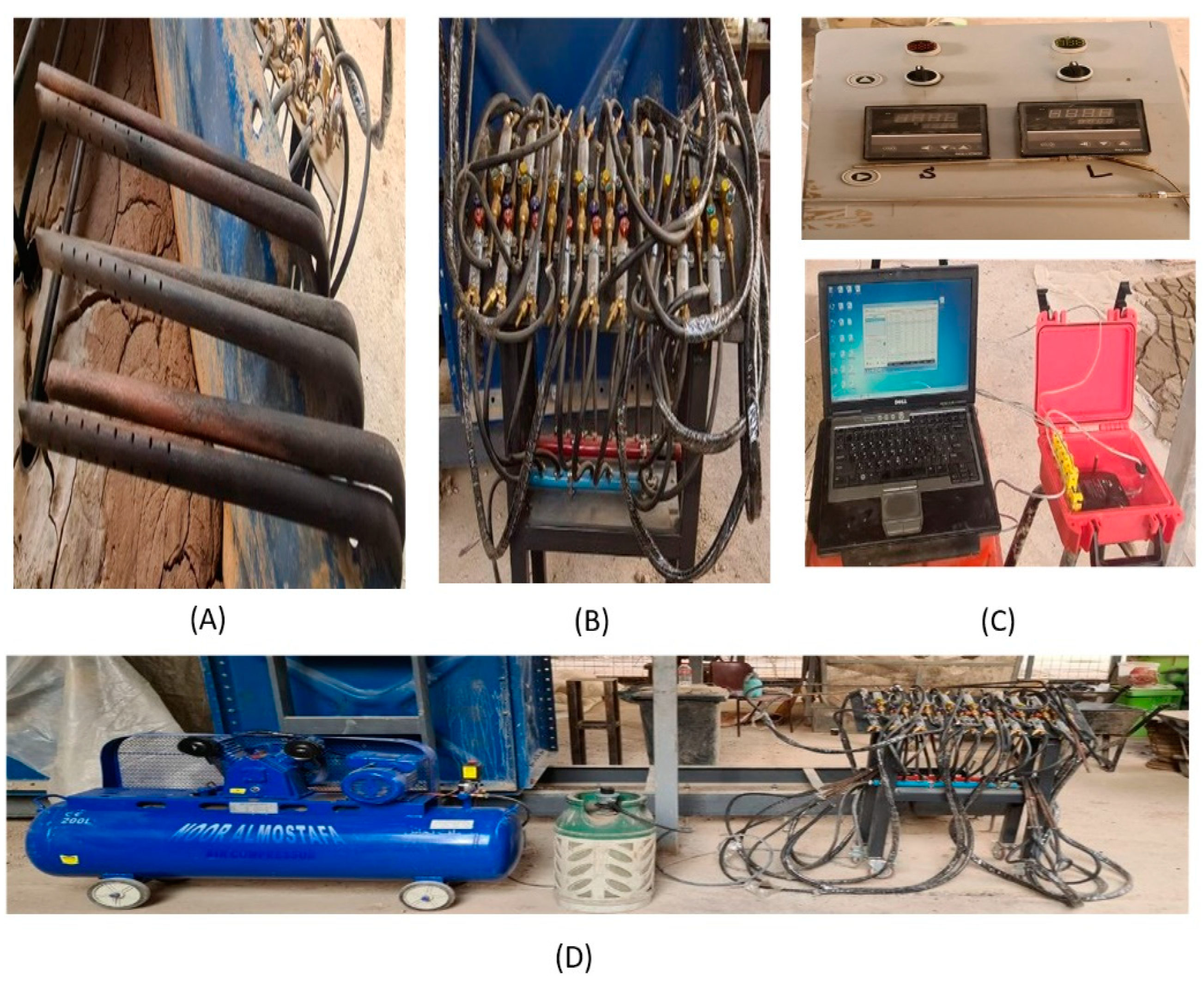
2.2.1. Metal Load Framework

A metal structure was created (simulated based on ASTM D1194 standard [26]) to sustain the verticality of the piston mechanism used to deliver the center-focused load onto the treated soil inside a metal box with interior dimensions (92.5 × 92.5 × 92.5) cm3, which held the penetration motor of the borehole casing throughout the heating process, as shown in Figure 2.

2.2.2. Casing (Barrier Tube)

The casing for the borehole was manufactured using four sizes of carbon steel according to A53 ASTM grade B, with a 43 mm outer diameter and a 4 mm thickness. Table 2 presents the physical properties of these cases. Various lengths (1, 1.5, 2, and 2.5 times the width of the model footing) were employed. The four varieties are shown in Figure 3. A previous experimental determination established that a minimum diameter of 35 mm is required to generate fire within the soil [27].

2.2.3. Heating System

The heating system was fabricated and installed to create heat inside the soil model. The system is composed of five major components: combustion pipes; rubber pipelines (W/BP 20/30 BAR) that transmit gas and air from the source to the priming pipes; a controller for the heating source; an air compressor that provides the heating system with air, along with a gas bottle and gas regulator; and the measuring devices for the heating system (Figure 4). Two devices are used to measure the temperature. The first is a heat control board with a plastic box holding two temperature controllers that monitor the soil’s internal temperature through a thermal connection. These temperature sensors (thermocables) are 15 and 30 cm in length, and they have two electric switches to activate the temperature controller and two electric lamps. The second device uses five thermal sensors linked by a thermal wire spread out within the soil to measure the soil temperature during heating. These sensors’ lengths are equal to 30 cm. In addition, the sensors are linked to a data-logger-type Ordel 100 device that records the temperature that is then transmitted to the computer. To ensure the accuracy of the results, two models were created for each variable, with the first model containing seven thermal sensors and the second containing two sensors.

2.2.4. CPT Probe Device

This investigation determined the bearing capacity parameter values for the thermally modified soils using an electrical cone penetration probe (CPT) with a 1000 mm2 cross-sectional area, as per ASTM D5778 [17]. The influence of the overburden pressure resulting from the shallow penetration depth was disregarded. Figure 5 illustrates that the penetrating motor was linked to this probe via a standard adapter. The penetration probe’s 10 mm/s velocity remained consistent due to the shallow penetration level.

2.3. Establishing the Soil Modeling and Test Procedure

An undrained shear strength (Cu) of 14 kPa was used with 29% water per 25 kg of dry clay soil, where the vane shear, a portable device, was used to achieve an undrained shear strength of the soil equal to 14 kPa. A 120 L laboratory mixer was used for blending. The soil was sealed in polythene bags for one day after mixing to obtain uniform moisture content. Afterward, the soil was deposited 10 cm deep for each layer in a (92.5 × 92.5 × 92.5) cm3 metal container and gently compressed with a 60 × 60 mm wooden tamper to remove air. After the final layer, the top surface was cleaned and leveled, and a hardwood platform with the same surface area as the bed’s soil was placed on the bed with 5 kPa of sitting pressure for one day. After removing the sitting pressure, the guide plate was placed according to the different arrangements, spacings, and lengths of the nine borehole cases to complete the installation of those cases; a motor was used that penetrated with a controlled velocity, and then an auger with a 34.5 mm diameter was used to empty the soils from inside the cases. After this step, the guide plate and motor were removed from the soil, and the model was prepared for heating. The heating pipes (combustion hands) started the heating stage. After inserting the casing into the soil and arranging the gas and air ratio (10% gas, 90% air), the heating system was activated, and the heat began to pass from the casing to the soil. Pipe primers ignited the casing fire.
After the operation, the heating equipment was switched off, and the soil model was allowed to reach ambient temperature after 24 h. After preparing the test model, the 20 cm × 20 cm footing was placed in the middle of the soil surface. The metal box was moved to align the foundation, and the motor pressurized the centers with a loading rate of 1 mm/min. Then, the loading transducer and LVDT were installed. Failure was defined as a load sufficient to induce a settlement equal to 10% of the footing width, although the influence of water vapor that escapes from the top layer causes massive cracks to occur in this layer; a 2 cm (10% of the footing width) depth settlement is a very weak criterion in this state. So, in this research, all models addressed a settlement equal to 15% of the footing width caused by the failure load. This research relied on the bearing ratio and settlement ratio. The definition of the bearing ratio is the compressive stress for treated soil (qu) divided by the undrained shear strength (Cu = 14 kPa). The settlement ratio is the settlement of the treated soil divided by the width of the footing test (20 cm). Lastly, Figure 6 shows the stages in the preparation of the soil model for the heat treatment and the load test.

2.4. Testing Program

The research approach used in this study was constrained to a series of five sequential processes including the analysis of physical models, as shown in Figure 7.

3. Test Results and Discussion

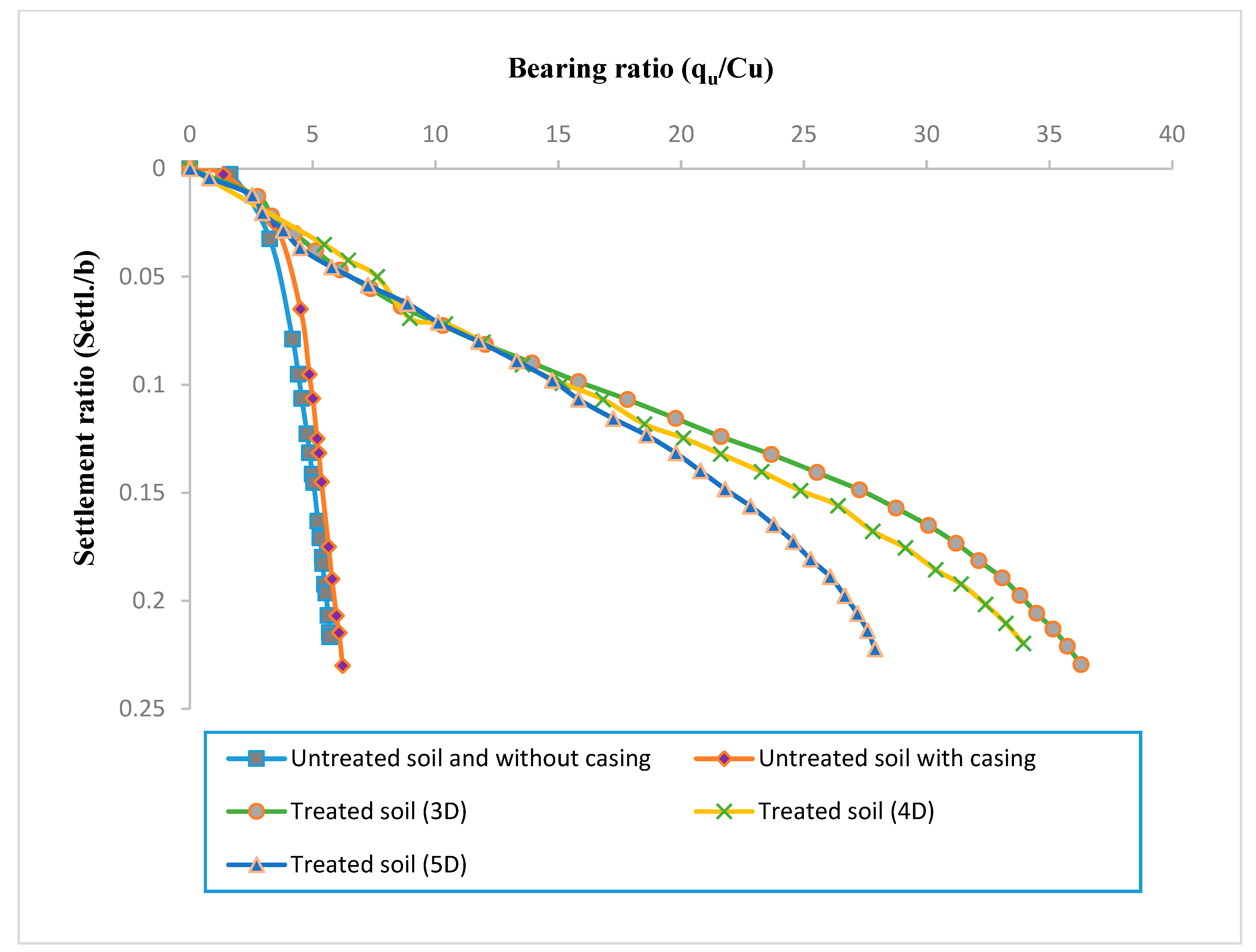
3.1. Effect of the Distance between the Borehole Casings (Spacing)

Three models were executed with nine square arrangements of heating boreholes at 40 cm depth (2b), with 3D (13 cm), 4D (17 cm), and 5D (22 cm) as the distances between each borehole. Each model was subjected to six hours of heating. The connection was dimensionless between the bearing ratio (qu/Cu) and the settlement ratio (Settl./bfooting) for all models, as shown in Figure 8. The values of the bearing ratio (qu/Cu) rise when the heating system operates and decrease when the distance between the heating boreholes increases up to a spacing of 5D, where the values of the bearing ratio at the 15% settlement ratio are 5.03, 5.35, 27.26, 24.84, and 21.78 for the models U.W (untreated soil without casing), U.C (untreated soil with casing), 3D, 4D, and 5D, respectively. For spacing increases greater than 3D, such as 4D and 5D, the interlocking between the unit cells is significant and leads to lower temperatures in the center of the treated zone, followed by low values for the bearing ratio, as shown in Figure 9. When the spacing is narrow, as in the 3D model, the unit cells become increasingly interlocked, and the temperature is higher than between the 4D and 5D models, as seen in Figure 10 and Figure 11 (the mechanical properties and chemical changes caused by the heating are discussed in the last section).

3.2. Effect of the Borehole Casing Depth

Four models with 3D (13 cm) spacing were designed to examine the effect of the borehole casing depth on the bearing capacity. Casing boreholes of varying depths and a square arrangement made with nine borehole casings were used to create all the models (b, 1.5b, 2b, and 2.5b), where b is the width of the model footing. There was a standard six-hour heating period for all models. Figure 12 illustrates the dimensionless relationship between the bearing and settlement ratios for all models with various depths, including U.W and U.C. The magnitude of the bearing ratios rises as the borehole casing depth increases. The bearing ratios are 5.03, 5.35, 14.23, 23.57, 27.26, and 28.2 for models U.W, U.C, 1b, 1.5b, 2b, and 2.5b, respectively. The results of all the models are attributed to two factors, the depth and the area on which the load acted, as illustrated in Figure 13. According to the stress bulb, the stress pressures dissipate with depth, with roughly 40% vanishing at less than 2b depth and 80% at more than 2b depth.

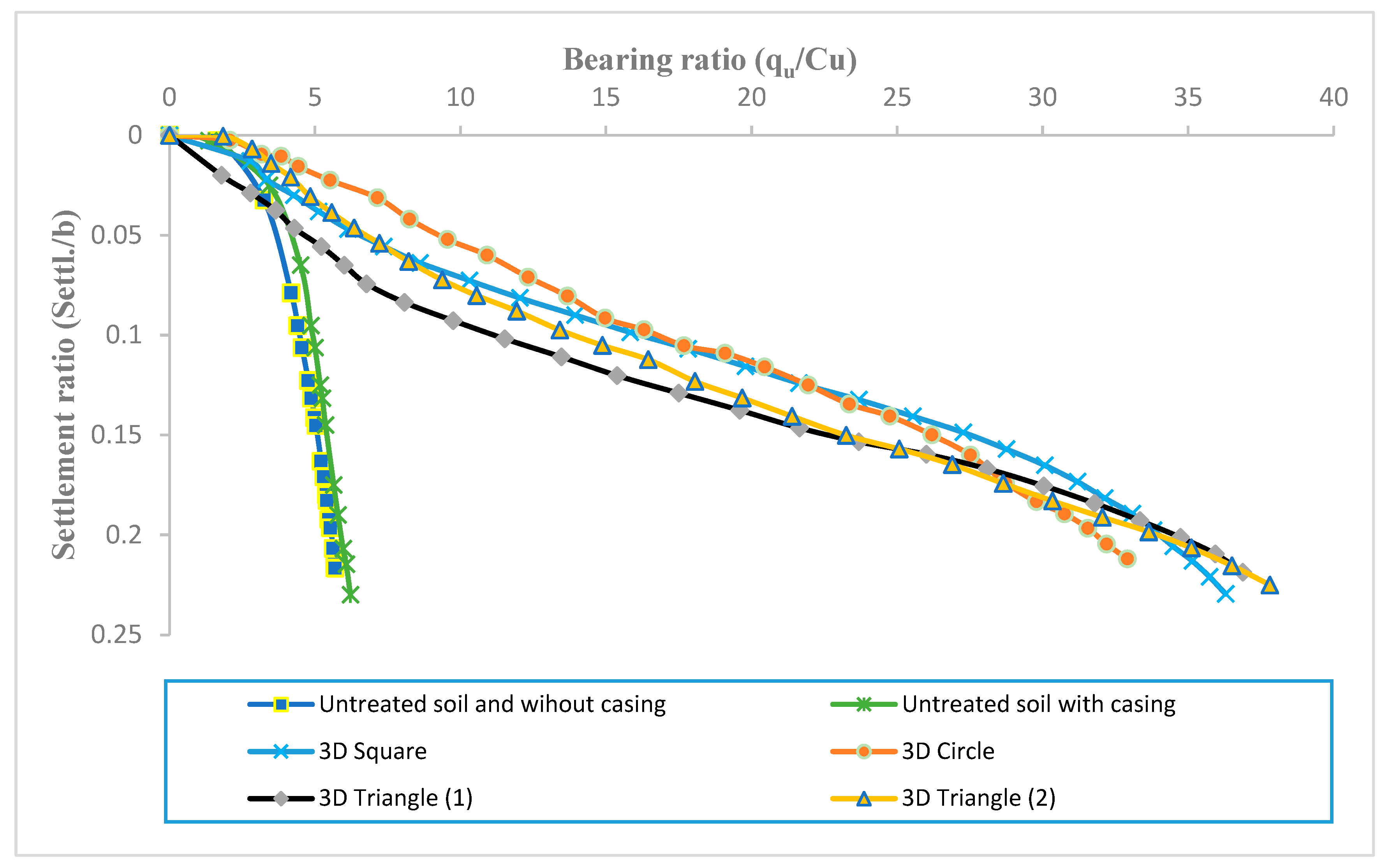
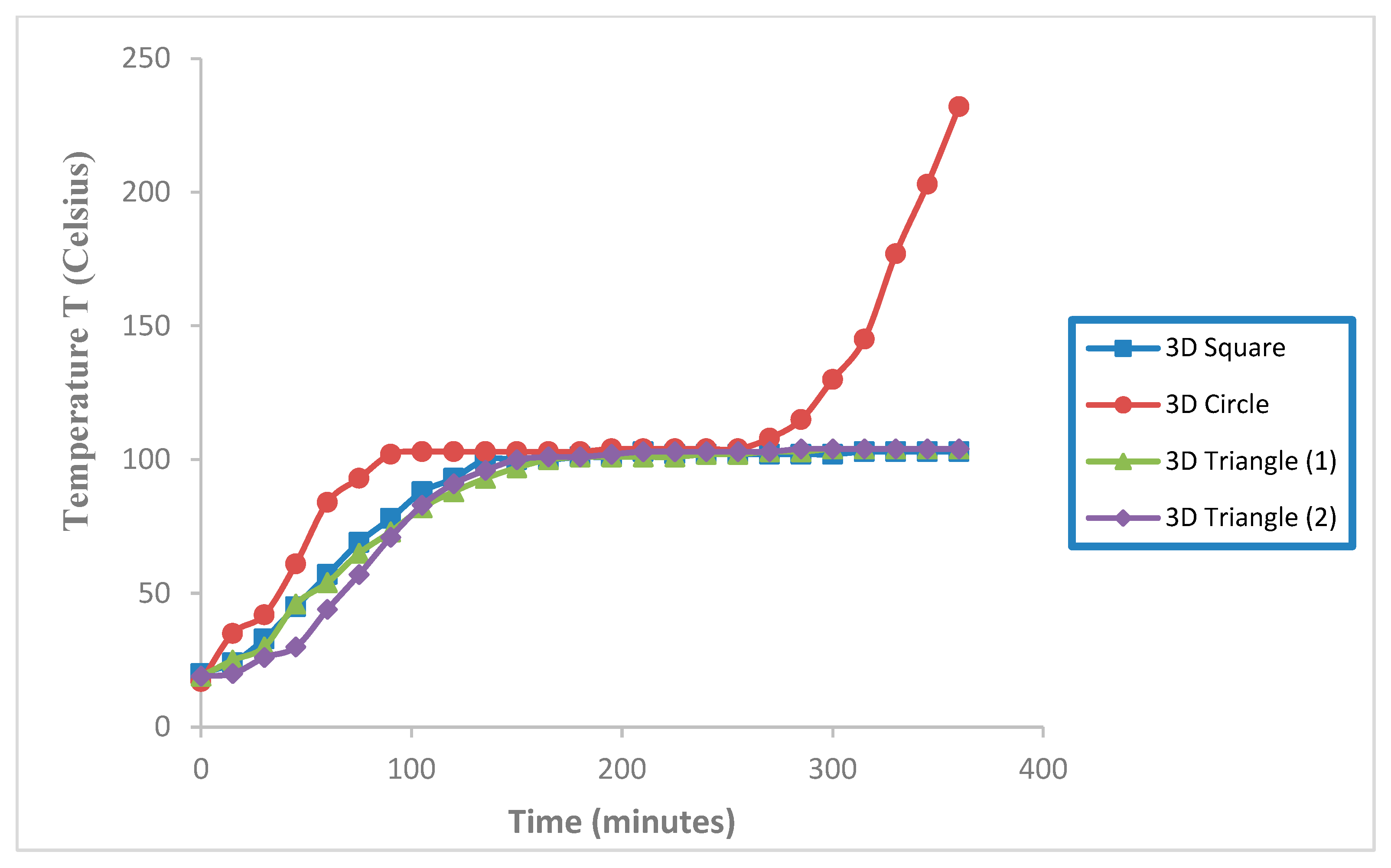
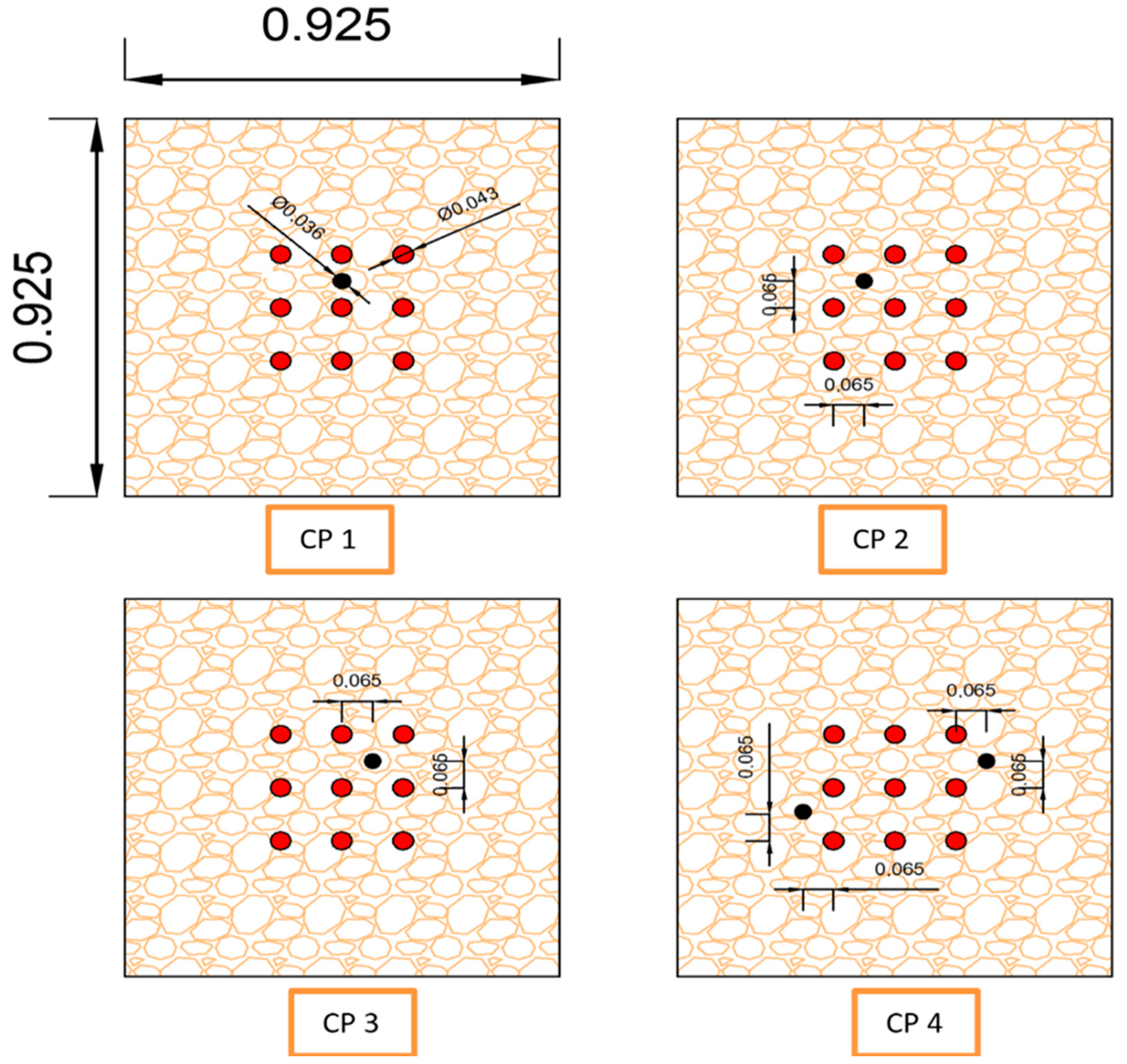
3.3. Effect of the Borehole Casing Arrangement

To evaluate the effect of the arrangement of the borehole heating casings on the bearing capacity, nine borehole casings with an inner diameter of 3.5 cm, a depth of 40 cm, and a spacing distance of 3D were produced to generate four models with varied arrangements: square, circle, triangle (1) (with one borehole heating casing under the footing), and triangle (2) (two borehole heating casings under the foundation). Figure 14 illustrates the dimensionless relationship between the bearing and settlement ratios for all models with various arrangements, including U.W and U.C. At the beginning of the study, we anticipated that the arrangement would have a substantial influence, but the differences were small. As shown in Figure 14, the bearing ratio values were 27.26, 26.19, 23.6, and 23.25 for the models 3D square, 3D circle, 3D triangle (2), and 3D triangle (1), respectively. In the triangular arrangement models, the treated area was inconsistent around the footing, where the unit cell interlocking was dispersed, and the bearing ratio was low compared to the square arrangement models, as seen in Figure 15. As a result of the close proximity between the small treated zone and the interlocking unit cells, resulting in the borehole heating casing, the bearing ratio of the circular arrangement was lower than that of the square design, as seen in Figure 16. Figure 17 and Figure 18 indicate the temperature fluctuations over time at the midpoint of the treatment zones for the 15 and 30 cm thermocables for all models, respectively. Figure 17 and Figure 18 show that the values were varied, most notably in the circular arrangement, where the temperature increased to 232 and 160 degrees Celsius. In comparison, it reached 104 degrees Celsius in the square and rectangular designs at the 15 and 30 cm thermocable lengths, respectively.

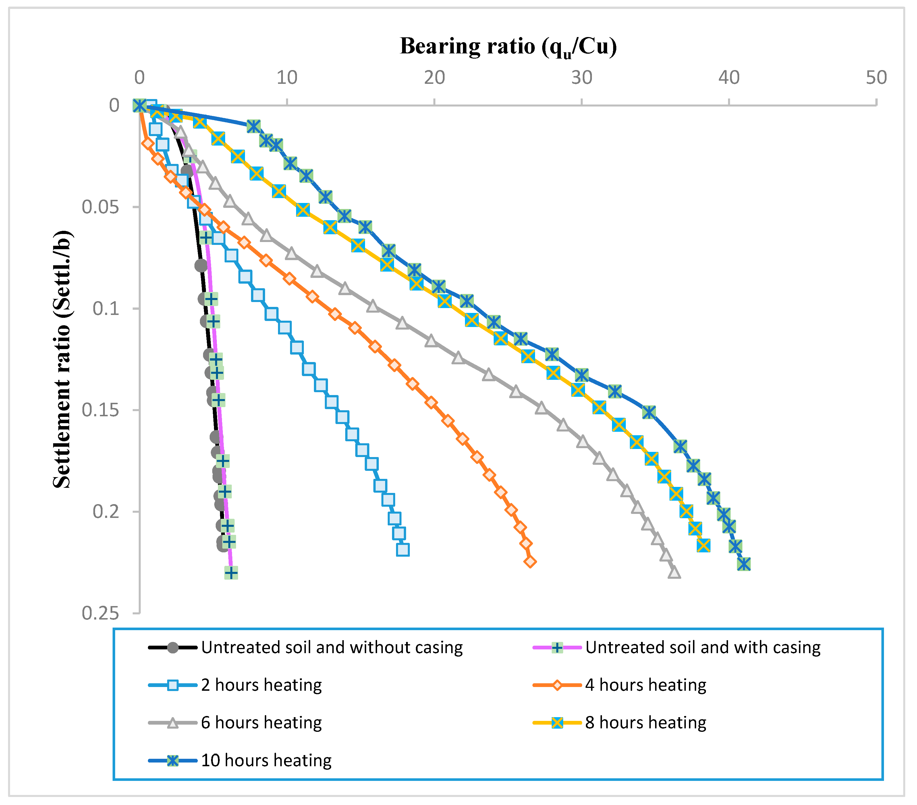
3.4. Effect of the Heating Time

Five models using the square arrangement were created to investigate the effect of the heating time on the bearing capacity. The models were heated for varying lengths of time (2, 4, 6, 8, and 10 h). The spacing and the extended depth of the borehole casings were 3D and 40 cm (2b), respectively. Figure 19 depicts the dimensionless relationship between the bearing and settlement ratios for all models with varying heating duration ratios. Figure 19 demonstrates that the bearing capacity values rose as the heating duration increased, because the bearing capacity parameters increased when the bearing ratios were 5.03, 5.35, 13.76, 20.9, 27.26, 31.19, and 34.57 for models U.W, U.C, 2 h, 4 h, 6 h, 8 h, and 10 h, respectively. Significantly, the angle of internal friction where the heating method worked on dry soils transformed the clay mineral, which then behaved like sandy soil. Figure 20 and Figure 21 depict the temperature variations with time at the midpoint of the treatment regions for the 15 and 30 cm thermocable lengths for all models, respectively. During the first 120 min of heating, the temperature rose rapidly from 21 to 98 °C.
The temperature inside the soil model increased until equilibrium was reached at 104 °C, and it remained at this temperature for the next four hours. Then, the temperature rose rapidly from 101 to 250 °C at 600 min, indicating the occurrence of three distinct phases. In the first stage, the soil and water act as heat conduction bridges. The mixture of soil and water is a uniform heat conductor since the soil particles are entirely covered by water, rapidly increasing the soil’s internal temperature. The second stage lasts between 120 and 360 min. The temperature increase is relatively slow until it reaches the equilibrium point of 101 °C. When the temperature rises, the amount of water vapor progressively increases and eventually exits from the soil, causing the soil pores to expand. Heat is transmitted via water, steam, and soil particles as the temperature increases. When all the soil moisture has evaporated, the soil’s heat is transported via the soil particles and steam. The stage in which the soil temperature remains at around 101 °C and does not rise due to the presence of water vapor is known as the constant stage. After 360 min of heat treatment, the third stage occurs: the water vapor in the soil evaporates entirely, the soil becomes dry, the clay minerals transmit heat fully, and the temperature rises until it exceeds the temperature of the heating source. Thus, it may be concluded that the first and second phases are complete after 360 min, meaning that the soil’s water vapor has been released and the soil has become dry. The soil examined in [28] exhibited the same behavior. Figure 22 depicts the relationship between the temperature (degrees Celsius) and the horizontal distance of the treatment zone for the 2, 4, 6, 8, and 10 h models, with the peaks on these curves representing the source of heat. Also, due to the action of the heating system, where the air is pushed into the wells to provide continuous air to run the heating system and remove the trapped gases created by combustion, there is a minor fluctuation in the temperature.
The CPT test was used to determine the increase in the undrained shear strength and the angle of internal friction. Four models (CP 1, CP 2, CP 3, and CP 4) were created using the square arrangement with 3D distance spacing (13 cm) and a depth of 40 cm for the borehole casing. Figure 23 shows the locations of the CPT test points. The models were heated for 8 h. Figure 24 and Figure 25 show the increase in the undrained shear strength (Cu) and the angle of internal friction (Ø) with regard to the reference model (Cu = 14 kPa and Ø = 0). The increased values of the undrained shear strength and the angle of internal friction at the center of the heating model (CP 1) occurred from 14 to 360 kPa and 0 to 52 degrees, respectively. However, from the center of the heating model to the farthest point affected by the heating (CP 1 to CP 4), the bearing capacity parameter values (Cu and Ø) dropped from 360 to 140 kPa and from 52 to 16 degrees on average with the depth (h) of the heat-treated soil.
The thermal consolidation effect of the soil was responsible for an increase or decrease in the bearing ratio in the treated soils, where the parameters of the bearing capacity, the angle of internal friction, and the undrained shear strength increased or decreased depending on how close or far apart the borehole heating casings were. A rise in the temperature accelerated the movement of the suspended particles in the porous medium [29] as well as chemical changes within the treated soil. Figure 26, Figure 27, Figure 28, Figure 29, Figure 30 and Figure 31 illustrate the EDS (energy-dispersive spectroscopy) pattern for the untreated soil and treated soil with different temperatures. The specimens used in the EDS test were taken from the center of the physical model. Figure 32 illustrates the change in the elemental composition (mg/kg) at different temperatures. The figure shows that as the temperature rose from 100 to 300 °C, the proportions of silicon, aluminum, and iron decreased from 18.04, 5.73, and 6.3 to 10.24, 3.3, and 2.81 (mg/kg), respectively. As the temperature rose to 400 °C, the proportions of these elements increased to 18.28, 6.1, and 5.53, respectively. The increase became very small when the temperature reached 600 °C. However, when the temperature reached 200 °C, the percentage of calcium increased from 9.18 to 18.36 (mg/kg). When the temperature reached 400 °C, the percentage of calcium decreased significantly to 13.66 (mg/kg), and when the temperature reached 600 °C, it decreased even more to 12.21 (mg/kg). When the temperature reached 300 °C, the percentage of carbon increased from 8.27 to 12.62 (mg/kg), and when the temperature reached 400 °C, the percentage of this element fell to 7.5 (mg/kg). At this point, the percentage almost stabilized until the temperature reached 600 °C. Table 3 includes the elemental composition of the untreated and heat-treated soils.

4. Conclusions

Based on the findings of the current research, the following inferences can be made:
  • The bearing ratio decreases from 27.26 to 21.78 at a 15% settlement ratio when the spacing increases from 3D to 5D. The interlocking between unit cells is significant and reduces the temperature in the center of the treated zone.
  • At a 15% settlement ratio, the magnitude of the bearing ratio rises from 14.23 to 28.2 for models 1b to 2.5b as the borehole casing depth increases. Also, this substantial increase then gradually decreases from 27.26 to 28.2 for models 2b to 2.5b.
  • The effect of the casing arrangement is small when the borehole heating casing is used. The bearing ratio is 26.19 for the circle arrangement model, while the bearing ratio for the square arrangement model is higher at 27.26. The amount of heat gained determines the strength of the treated area. The greater the amount of heat in the footing center, the greater the strength of the heat-treated zone. Also, the correct distribution of the borehole heating casing increases the strength, which provides an appropriate treatment area according to the order of the stresses applied mainly to the treatment area consisting of interlocking unit cells.
  • The bearing ratio value increases from 13.76 to 34.57 for the 2–10 h heating duration models at a 15% settlement ratio. A small increase in the bearing ratio, from 31.19 to 34.57, is observed for the 8–10 h heating duration models. Also, the rate of improvement rises rapidly for the first six hours but diminishes after that.
  • The best spacing between boreholes is three times the outer diameter of the borehole, and the best borehole depth is two times the width of the foundation footing with 8 h of heating duration.
  • The values of the undrained shear strength and angle of internal friction at the center of the heating model (CP 1) increase from 14 to 360 kPa and 0 to 52 degrees, respectively.
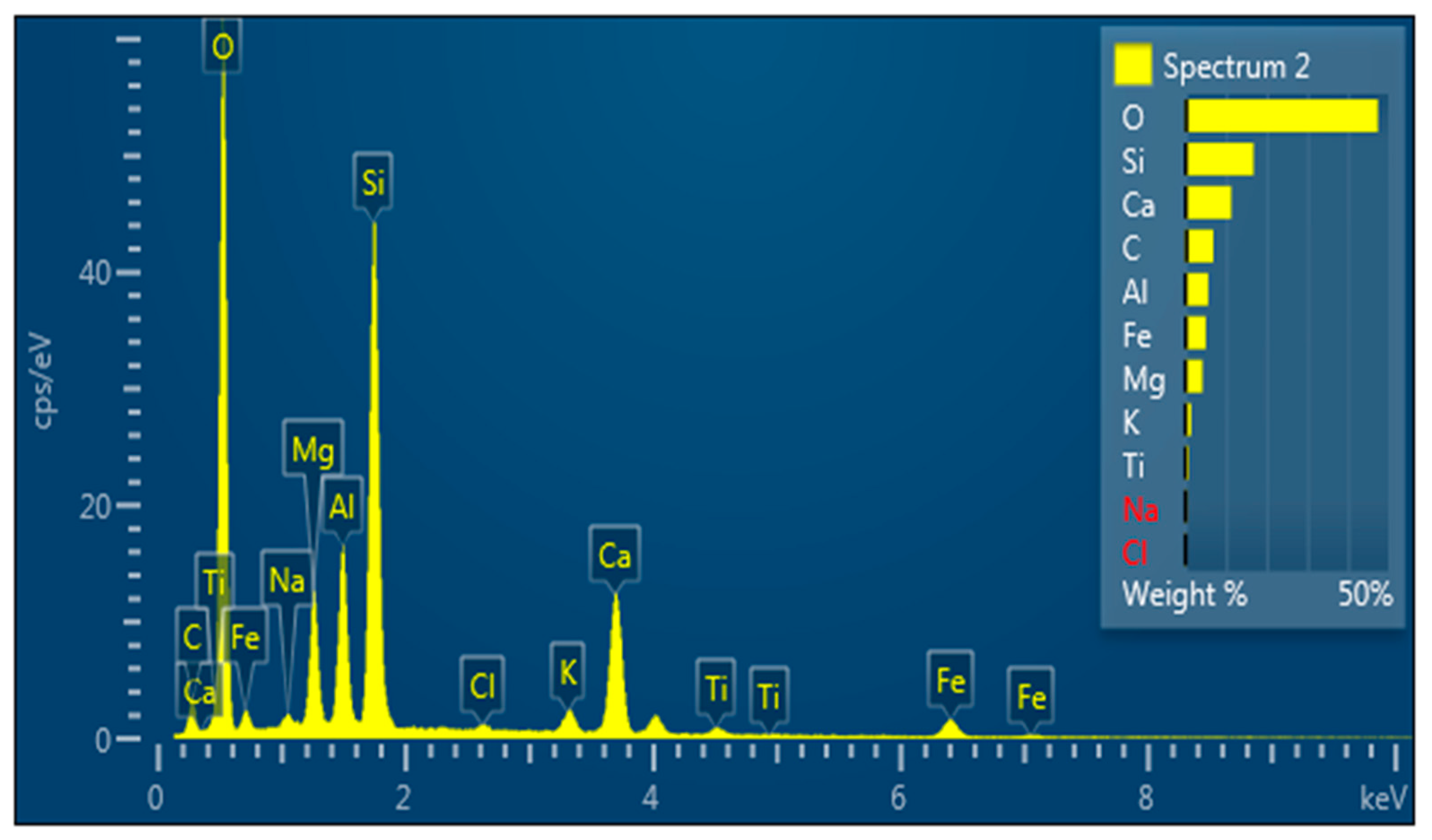
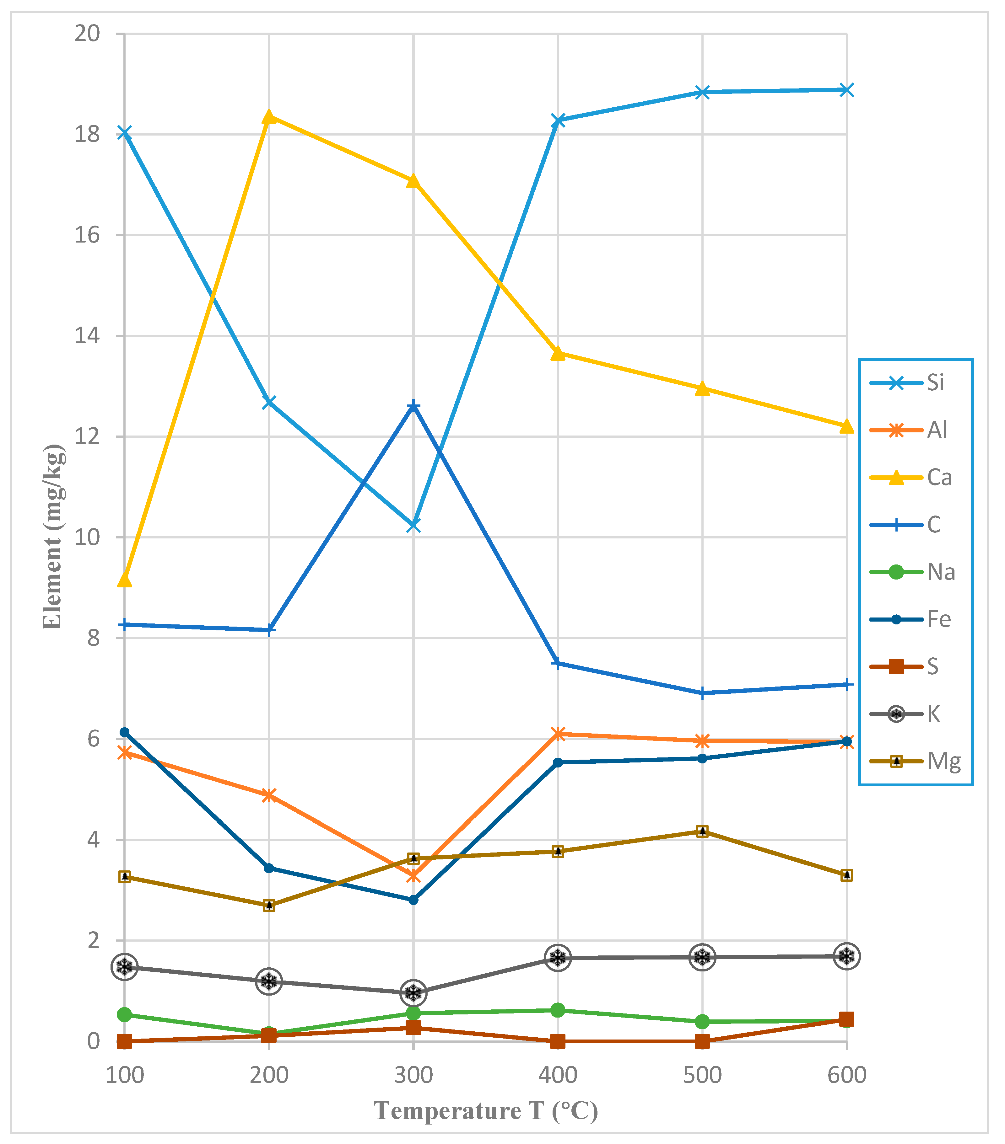
  • The EDS pattern for the treated soils demonstrates that the percentage of elements such as silicon, aluminum, and iron decreases at 300 °C and increases at 400 °C. Moreover, the percentage of calcium increases as the temperature reaches 200 °C and sharply decreases when it reaches 400 °C. The amount of carbon increases as the temperature rises to 300 °C and decreases at 400 °C.
  • The amounts of the measured elements exhibit either low or negligible fluctuations when the temperature falls within the range of 400 to 600 °C.

Author Contributions

A.H.S.: conceptualization, carrying out experimental research, writing—review and editing; M.A.A.-N.: writing—review and editing, supervision; F.H.R.: writing—original draft, supervision. All authors have read and agreed to the published version of the manuscript.

Funding

This research received no from any funding agency in the public, commercial, or not-for-profit sectors.

Data Availability Statement

The data that support the findings of this study are available on request from the corresponding author.

Conflicts of Interest

The authors declare no conflict of interest.

References

  1. Al-Neami, M.A.M. Reducing settlement of soft soils using local materials. Eng. Technol. J. 2010, 28, 6649–6661. [Google Scholar] [CrossRef]
  2. Sasanian, S. The Behaviour of Cement Stabilised Clay at High Water Contents; The University of Western Ontario: London, ON, Canada, 2011. [Google Scholar]
  3. Ahmed, A. Compressive strength and microstructure of soft clay soil stabilised with recycled bassanite. Appl. Clay Sci. 2015, 104, 27–35. [Google Scholar] [CrossRef]
  4. Sukpunya, A.; Jotisankasa, A. Large simple shear testing of soft Bangkok clay stabilised with soil–cement-columns and its application. Soils Found. 2016, 56, 640–651. [Google Scholar] [CrossRef]
  5. Wang, S.; Gainey, L.; Mackinnon, I.D.; Allen, C.; Gu, Y.; Xi, Y. Thermal behaviors of clay minerals as key components and additives for fired brick properties: A review. J. Build. Eng. 2022, 66, 105802. [Google Scholar] [CrossRef]
  6. Tan, Ö.; Yılmaz, L.; Zaimoğlu, A.S. Variation of some engineering properties of clays with heat treatment. Mater. Lett. 2004, 58, 1176–1179. [Google Scholar] [CrossRef]
  7. Abu-Zreig, M.M.; Al-Akhras, N.M.; Attom, M.F. Influence of heat treatment on the behavior of clayey soils. Appl. Clay Sci. 2001, 20, 129–135. [Google Scholar] [CrossRef]
  8. Sun, Q.; Zhang, W.; Qian, H. Effects of high temperature thermal treatment on the physical properties of clay. Environ. Earth Sci. 2016, 75, 610. [Google Scholar] [CrossRef]
  9. Geng, J.; Sun, Q. Effects of high temperature treatment on physical-thermal properties of clay. Thermochim. Acta 2018, 666, 148–155. [Google Scholar] [CrossRef]
  10. Hu, Q.; Gu, Y.; Zeng, J.; He, L.; Tang, H.; Wei, G.; Lu, X. Microwave irradiation reinforcement of weak muddy intercalation in slope. Appl. Clay Sci. 2019, 183, 105324. [Google Scholar] [CrossRef]
  11. Zhang, S.; Ding, Y.; Lu, X.; Mao, X.; Song, M. Rapid and efficient disposal of radioactive contaminated soil using microwave sintering method. Mater. Lett. 2016, 175, 165–168. [Google Scholar] [CrossRef]
  12. Chen, Z.; Zhu, H.; Yan, Z.; Zhao, L.; Shen, Y.; Misra, A. Experimental study on physical properties of soft soil after high temperature exposure. Eng. Geol. 2016, 204, 14–22. [Google Scholar] [CrossRef]
  13. Yin, T.; Liu, G.; Guo, Z. Theoretical and experimental study on thermal consolidation characteristics of typical soft clay in Ningbo region. Build. Struct. 2014, 44, 66–69. [Google Scholar]
  14. Chen, Y.; Sun, Z.; Cui, Y.; Ye, W.; Liu, Q. Effect of cement solutions on the swelling pressure of compacted GMZ bentonite at different temperatures. Constr. Build. Mater. 2019, 229, 116872. [Google Scholar] [CrossRef]
  15. Reinosa, J.J.; García-Baños, B.; Catalá-Civera, J.M.; Fernández, J.F. A step ahead on efficient microwave heating for kaolinite. Appl. Clay Sci. 2019, 168, 237–243. [Google Scholar] [CrossRef]
  16. Yao, H.; Lu, J.; Bian, H.; Zhang, Z. Influence of microwave heating on the swelling properties of expansive soil in Hefei. Case Stud. Therm. Eng. 2022, 39, 102466. [Google Scholar] [CrossRef]
  17. ASTM D5778; Standard Test Method for Electronic Friction Cone and Piezocone Penetration Testing of Soils. ASTM International: West Conshohocken, PA, USA, 1997.
  18. ASTM D4318; Standard Test Methods for Liquid Limit, Plastic Limit, and Plasticity Index of Soils. ASTM International: West Conshohocken, PA, USA, 2000.
  19. ASTM D854; Standard Test Methods for Specific Gravity of Soil Solids by Water Pycnometer, Annual Book of ASTM Standards. ASTM International: West Conshohocken, PA, USA, 2002.
  20. ASTM D422; Standard Test Method for Particle Size—Analysis of Soils. ASTM International: West Conshohocken, PA, USA, 2000.
  21. ASTM D2487; Standard Practice for Classification of Soils for Engineering Purposes (Unified Soil Classification System). ASTM International: West Conshohocken, PA, USA, 2000.
  22. ASTM D4974; Standard Test Methods for Determining the Water (Moisture) Content, Ash Content, and Organic Material of Peat and Other Organic Soils. Annual Book of ASTM Standards, Vol. 04.08. ASTM International: West Conshohocken, PA, USA, 2002.
  23. ASTM D5907; Standard Test Methods for Filter Matter (Total Dissolved Solids) and Nonfilterable Matter (Total Suspended Solids) in Water, Annual Book of ASTM Standards. ASTM International: West Conshohocken, PA, USA, 2002.
  24. ASTM D4972; Standard Test Method for pH of Soils. Annual Book of ASTM Standards, Vol. 04.08. ASTM International: West Conshohocken, PA, USA, 2002.
  25. Demirbas, A. Fuel properties of hydrogen, liquefied petroleum gas (LPG), and compressed natural gas (CNG) for transportation. Energy Sources 2002, 24, 601–610. [Google Scholar] [CrossRef]
  26. ASTM D1194; Standard Test Method for Bearing Capacity of Soil for Static Load and Spread Footings. ASTM International: West Conshohocken, PA, USA, 1994.
  27. Rahil, F.; Baqir, H.; Alkabee, H. Bearing capacity of soft clay improved by heating through different spacing cased boreholes. Kufa J. Eng. 2019, 10, 68–77. [Google Scholar] [CrossRef]
  28. Bai, B.; Long, F.; Rao, D.; Xu, T. The effect of temperature on the seepage transport of suspended particles in a porous medium. Hydrol. Process. 2017, 31, 382–393. [Google Scholar] [CrossRef]
  29. Zhu, H.; Chen, Z.; Wang, Y.; Yan, Z. Experimental investigation on heat transfer characteristics of soft clay at high temperatures. Jpn Geotech. Soc. Spec. Publ. 2015, 1, 40–44. [Google Scholar] [CrossRef]
Figure 1. Grain size of soil.
Minerals 14 00041 g001
Figure 2. Metal load framework.
Minerals 14 00041 g002
Figure 3. Tube casing of the borehole.
Minerals 14 00041 g003
Figure 4. Heating system: (A) combustion pipes, (B) heating source controller, (C) heating system measuring devices, and (D) air compressor, gas bottle, and gas regulator.
Minerals 14 00041 g004
Figure 5. Preparing the CPT probe to model the test.
Minerals 14 00041 g005
Figure 6. Stages in the test procedure for the heat treatment and load test.
Minerals 14 00041 g006
Figure 7. Flowchart of the testing program.
Minerals 14 00041 g007
Figure 8. Dimensionless connection between the bearing ratio and the settlement ratio for various spacing models.
Minerals 14 00041 g008
Figure 9. Images showing the areas enhanced by the heating technique: (A) 3D model and (B) 5D model.
Minerals 14 00041 g009
Figure 10. Temperature and duration for the 15 cm thermocable at various spacings.
Minerals 14 00041 g010
Figure 11. Temperature and duration for the 30 cm thermocable at various spacings.
Minerals 14 00041 g011
Figure 12. Dimensionless connection between the bearing ratio and the settlement ratio for various depth models.
Minerals 14 00041 g012
Figure 13. Enhancement area at various depths: (A) 20 cm (b), (B) 30 cm (1.5b), (C) 40 cm (2b), and (D) 50 cm (2.5b).
Minerals 14 00041 g013
Figure 14. Dimensionless connection between the bearing ratio and the settlement ratio for various casing arrangements.
Minerals 14 00041 g014
Figure 15. Triangular arrangement model: (A) triangle (2) (two borehole heating casings under footing), and (B) triangle (1) (one borehole heating casing under footing).
Minerals 14 00041 g015
Figure 16. Circular casing arrangement.
Minerals 14 00041 g016
Figure 17. Relationship between temperature and duration for the 15 cm thermocable in various arrangements.
Minerals 14 00041 g017
Figure 18. Relationship between temperature and duration for the 30 cm thermocable in various arrangements.
Minerals 14 00041 g018
Figure 19. Dimensionless connection between the bearing ratio and settlement ratio for various heating times.
Minerals 14 00041 g019
Figure 20. Relationship between temperature and duration for the 15 cm thermocable for various heating times.
Minerals 14 00041 g020
Figure 21. Relationship between temperature and duration for the 30 cm thermocable for various heating times.
Minerals 14 00041 g021
Figure 22. Relationship between temperature and horizontal distance for the 2, 4, 6, 8, and 10 h models.
Minerals 14 00041 g022
Figure 23. Location of CPT test points (all dimensions in meters).
Minerals 14 00041 g023
Figure 24. Variation in the undrained shear strength with depth.
Minerals 14 00041 g024
Figure 25. Variation in the angle of internal friction (Ø) with depth.
Minerals 14 00041 g025
Figure 26. EDS pattern for the untreated soil.
Minerals 14 00041 g026
Figure 27. EDS of the soil treated at 200 °C.
Minerals 14 00041 g027
Figure 28. EDS of the soil treated at 300 °C.
Minerals 14 00041 g028
Figure 29. EDS of the soil treated at 400 °C.
Minerals 14 00041 g029
Figure 30. EDS of the soil treated at 500 °C.
Minerals 14 00041 g030
Figure 31. EDS of the soil treated at 600 °C.
Minerals 14 00041 g031
Figure 32. Change in the elemental composition (mg/kg) at different temperatures.
Minerals 14 00041 g032
Table 1. Physicochemical properties of the soil.
Index PropertyTest StandardIndex Value
Liquid Limit (LL) (%)ASTM D431845
Plastic Limit (PL) (%)ASTM D431823
Plasticity Index (PI) (%)ASTM D431822
Specific Gravity (G.s)ASTM D8542.69
Gravel (larger than 4.75 mm) (G) %ASTM D4220
Sand (0.075 to 4.75 mm) (S) %ASTM D4222
Silt (0.005 to 0.075 mm) (M) %ASTM D42220
Clay (less than 0.005 mm) (C) %ASTM D42278
Classification (USCS)ASTM D2487CL
Organic Matter (OM) (%)ASTM D2974<0.01
Total Dissolved Solids (TDS %)ASTM D59072.21
pHASTM D49727.2
Table 2. Physical properties of the pipe casing (based on factory specifications).
PropertyValue
Density at 20 °C, ρ20 (kg/dm3)785
Thermal conductivity at 20 °C, κ20 (W/m K)50
Specific thermal capacity at 20 °C, ϲ20 (J/kg K)460
Table 3. Elemental composition (from the EDS analysis) of the untreated soil and treated soil.
ElementUntreated SoilSoil Treated at 200 °CTreated Soil at 300 °CSoil Treated at 400 °CSoil Treated at 500 °CSoil Treated at 600 °C
Weight (W) (mg/kg)Weight (W) (mg/kg)Weight (W) (mg/kg)Weight (W) (mg/kg)Weight (W) (mg/kg)Weight (W) (mg/kg)
Si18.0412.6810.2418.2818.8418.89
O47.3947.2646.3742.2942.9143.69
Al5.734.883.36.15.965.94
C8.278.1612.627.56.917.08
Ca9.1618.3617.0813.6612.9612.21
Na0.530.150.560.620.390.41
K1.481.190.961.661.671.69
Fe6.133.442.815.535.615.95
Mg3.272.73.633.774.173.3
S00.110.27000.44
Cl00.121.670.520.280.36
Disclaimer/Publisher’s Note: The statements, opinions and data contained in all publications are solely those of the individual author(s) and contributor(s) and not of MDPI and/or the editor(s). MDPI and/or the editor(s) disclaim responsibility for any injury to people or property resulting from any ideas, methods, instructions or products referred to in the content.

