
Investigation of Hydrated Dy(III) and MgSO4 Leaching Agent Ion Adsorption on (001) Surface of Montmorillonite: A Study Using Density Functional Theory
 , , ,
, , , 
Abstract
:1. Introduction
2. Kaolinite Structure
3. Calculation Method and Model
4. Results and Discussion
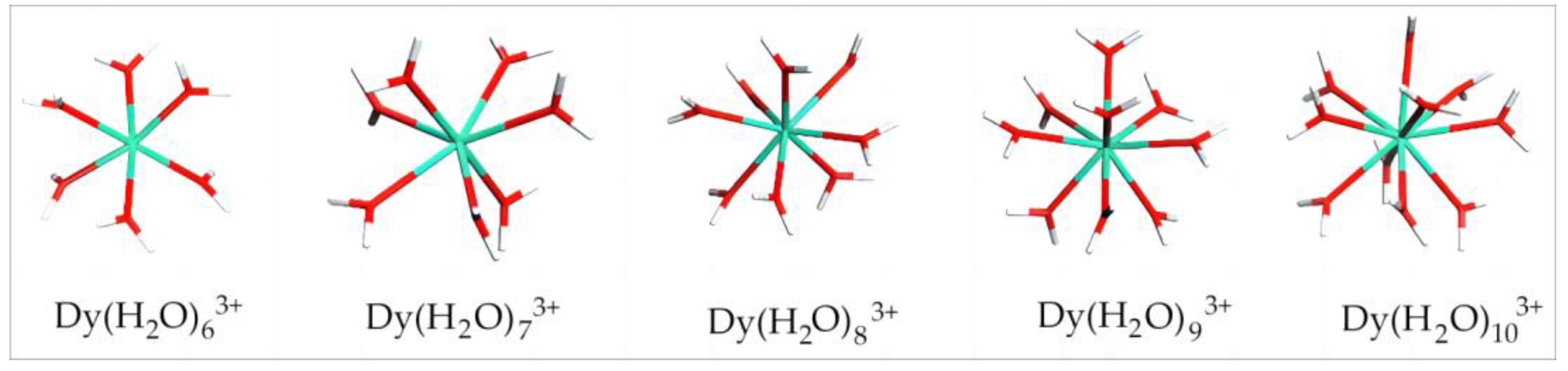
4.1. Stable Configuration of Hydrated Dy(III)
4.1.1. Equilibrium Configuration Parameter and Binding Energy of Dy(H2O)n3+
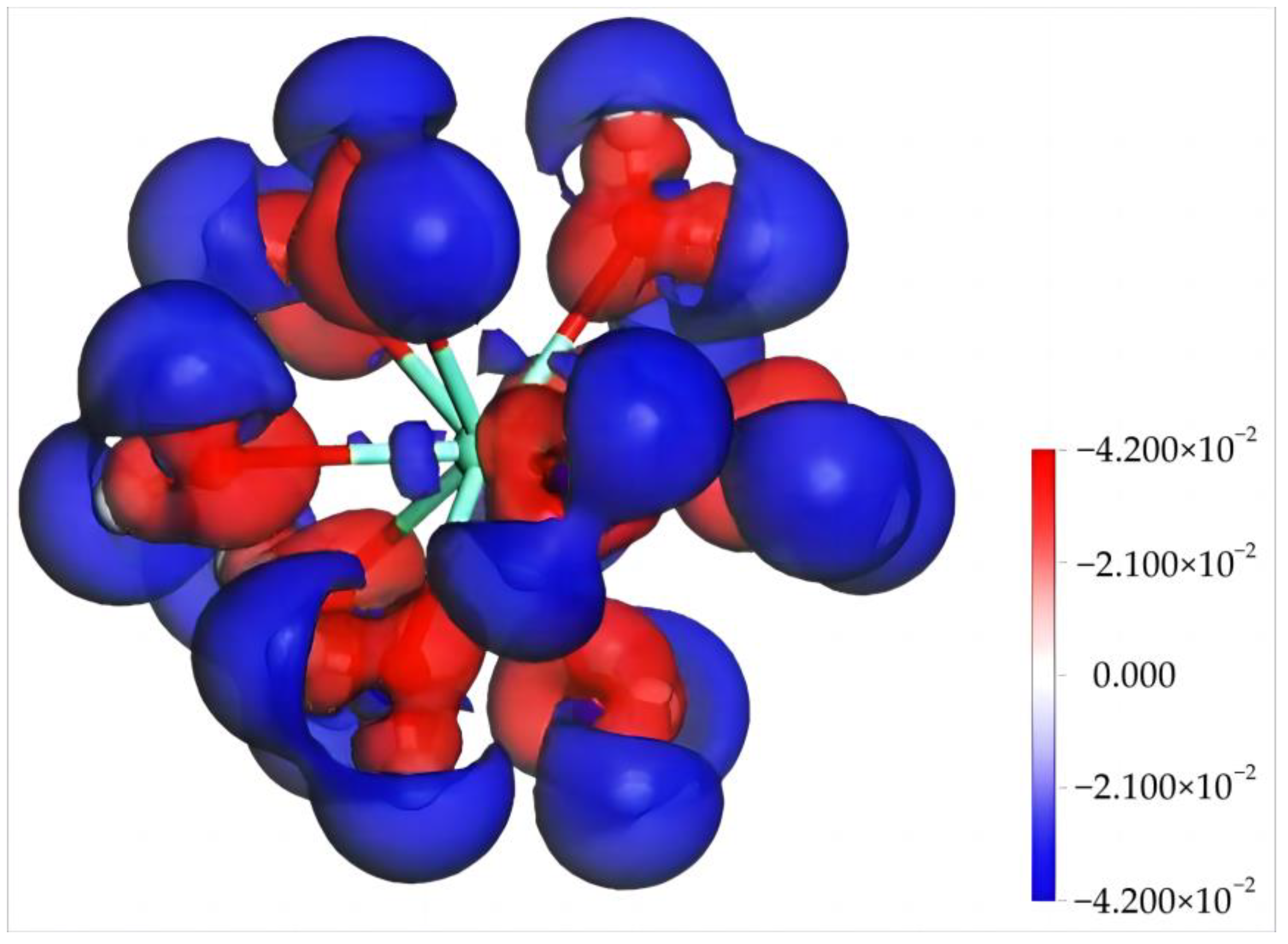
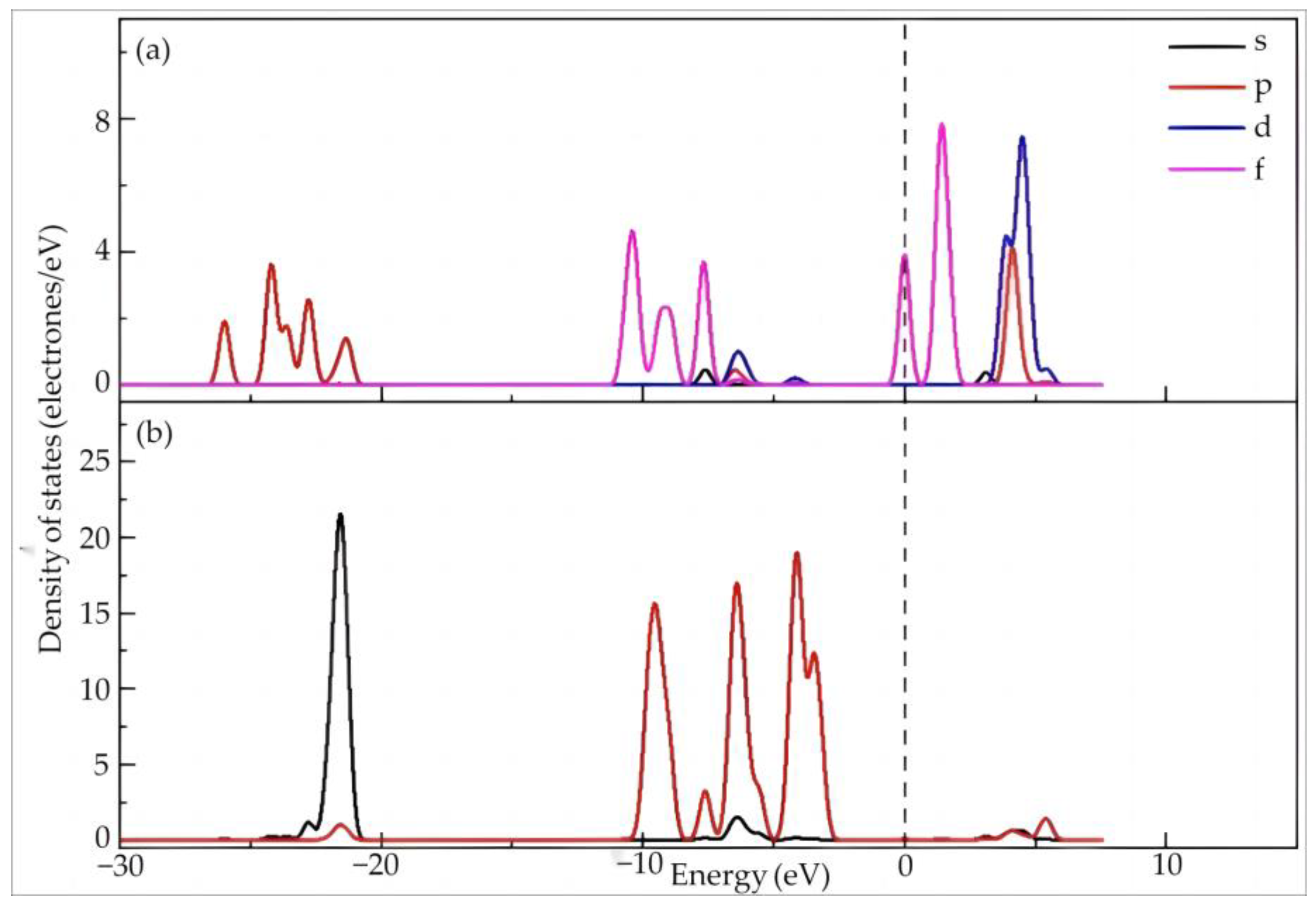
4.1.2. Electronic Structure and Properties of Dy(H2O)103+
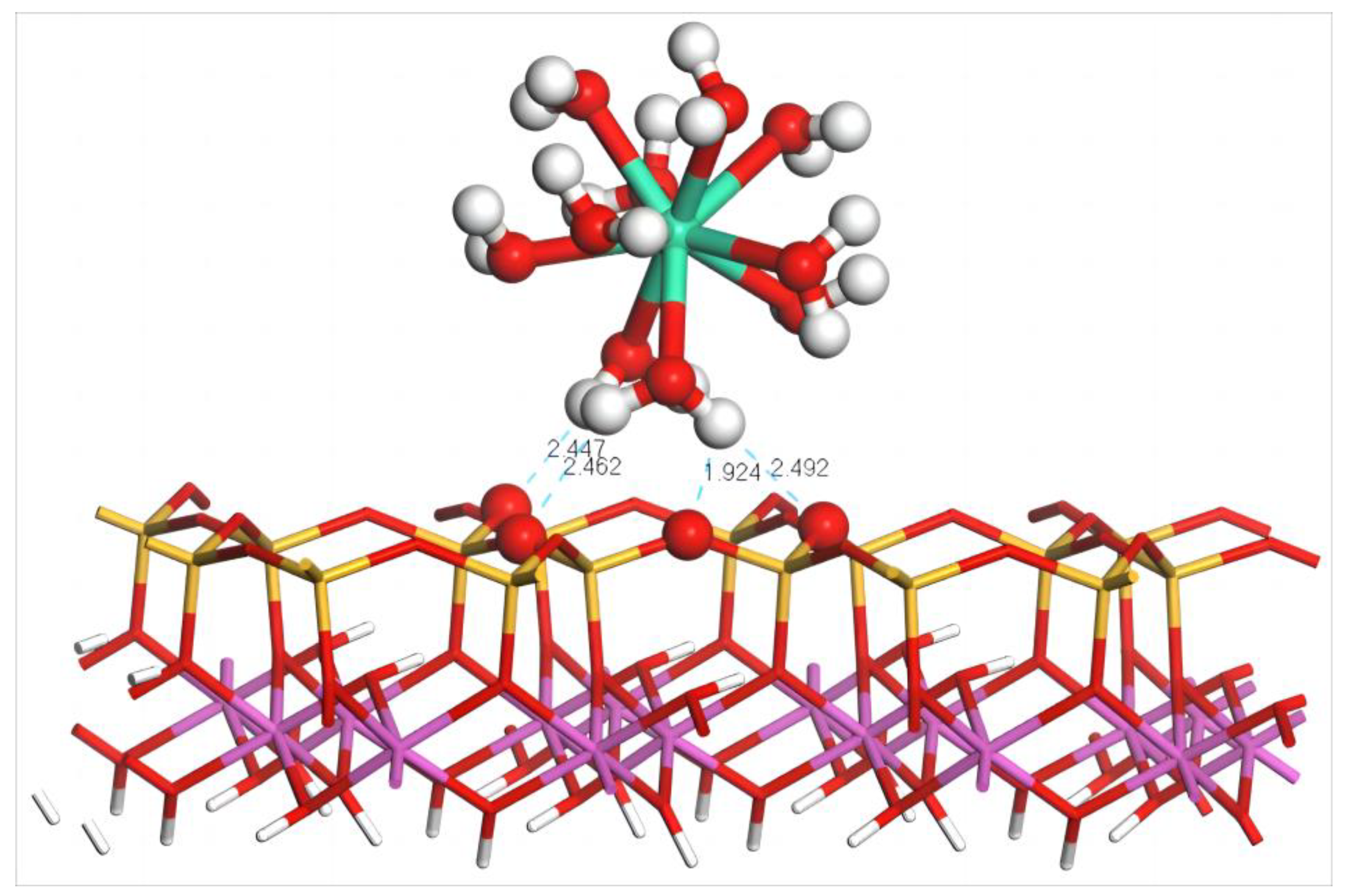
4.2. Adsorption of Dy(H2O)103+ Ions on the Silico–Oxygen Plane of Kaolinite
4.2.1. Adsorption Configuration and Adsorption Energy of Dy(H2O)103+
4.2.2. Dy(H2O)103+ Electron Transfer and State Density Study
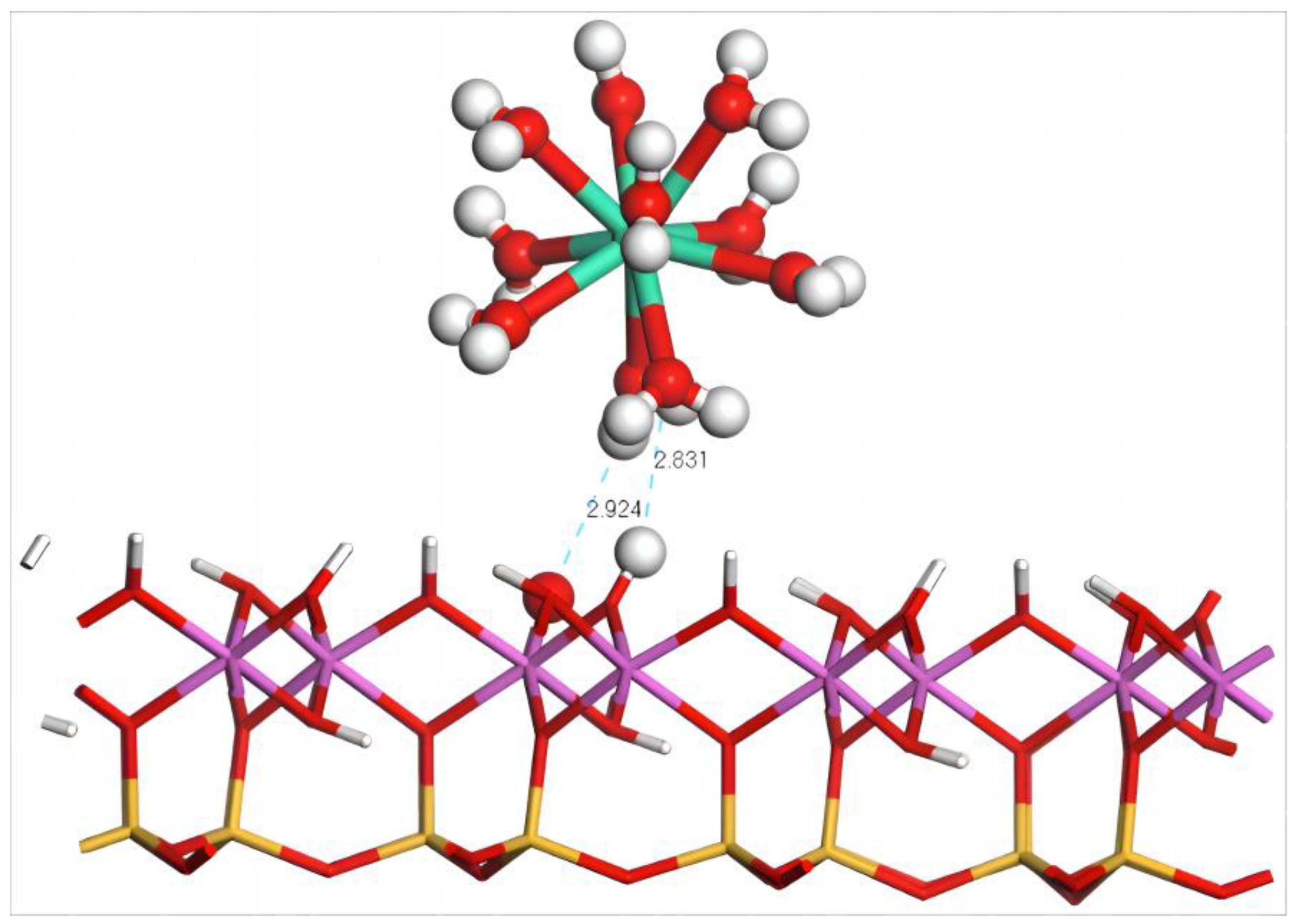
4.3. Adsorption of Dy(H2O)103+ Ions on the Aluminum–Hydroxyl Plane of Kaolinite
4.3.1. Adsorption Configuration and Adsorption Energy of Dy(H2O)103+
4.3.2. State Density and Electron Transfer of Dy(H2O)103+
4.4. Adsorption of Cations and Anions of MgSO4 Leaching Agent on Kaolinite Surface
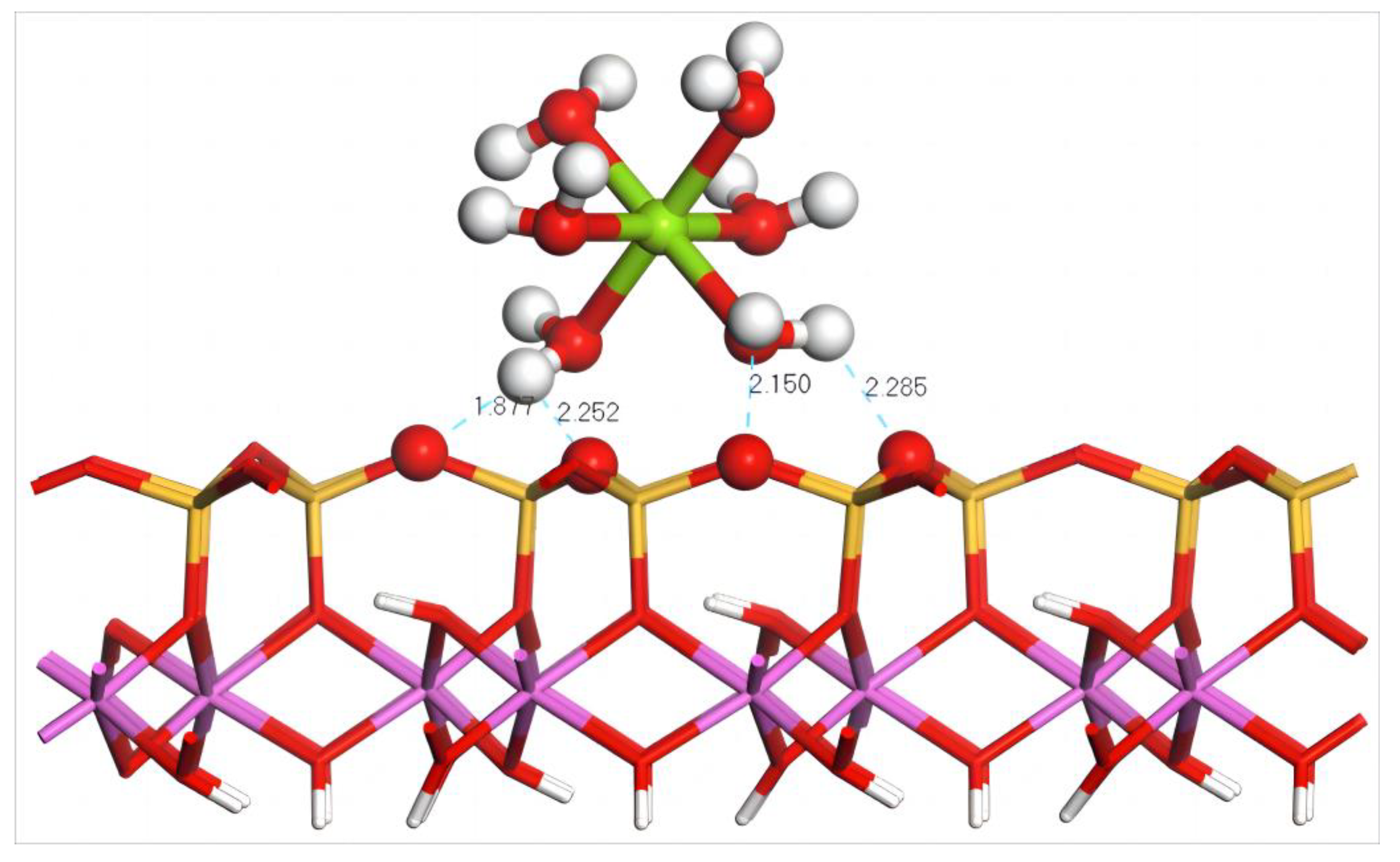
4.4.1. Adsorption of Mg(H2O)62+ on the Silico–Oxygen Plane of Kaolinite
- (1)
- Adsorption Configuration and Adsorption Energy
- (2)
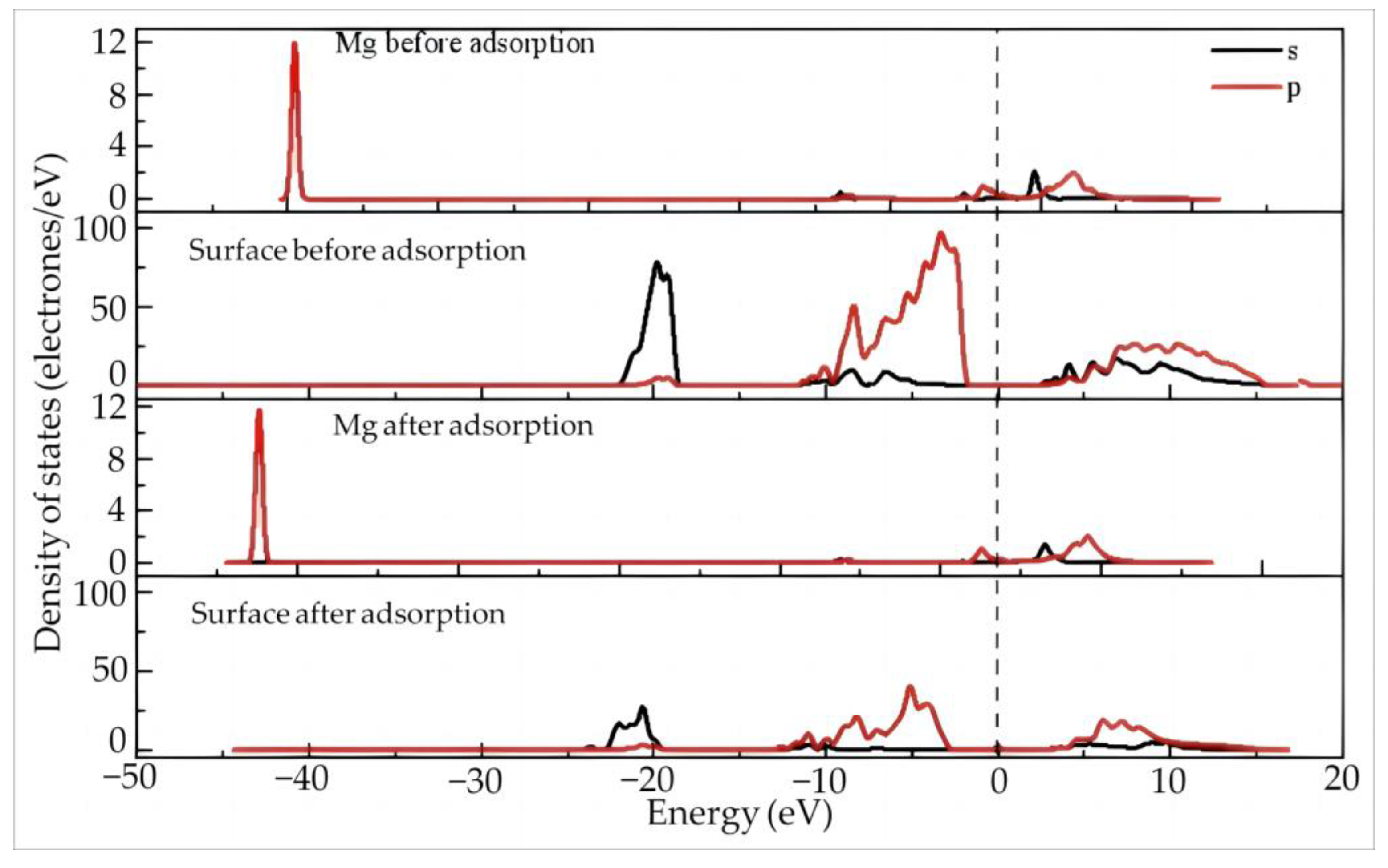
- Electron Transfer and State Density Study
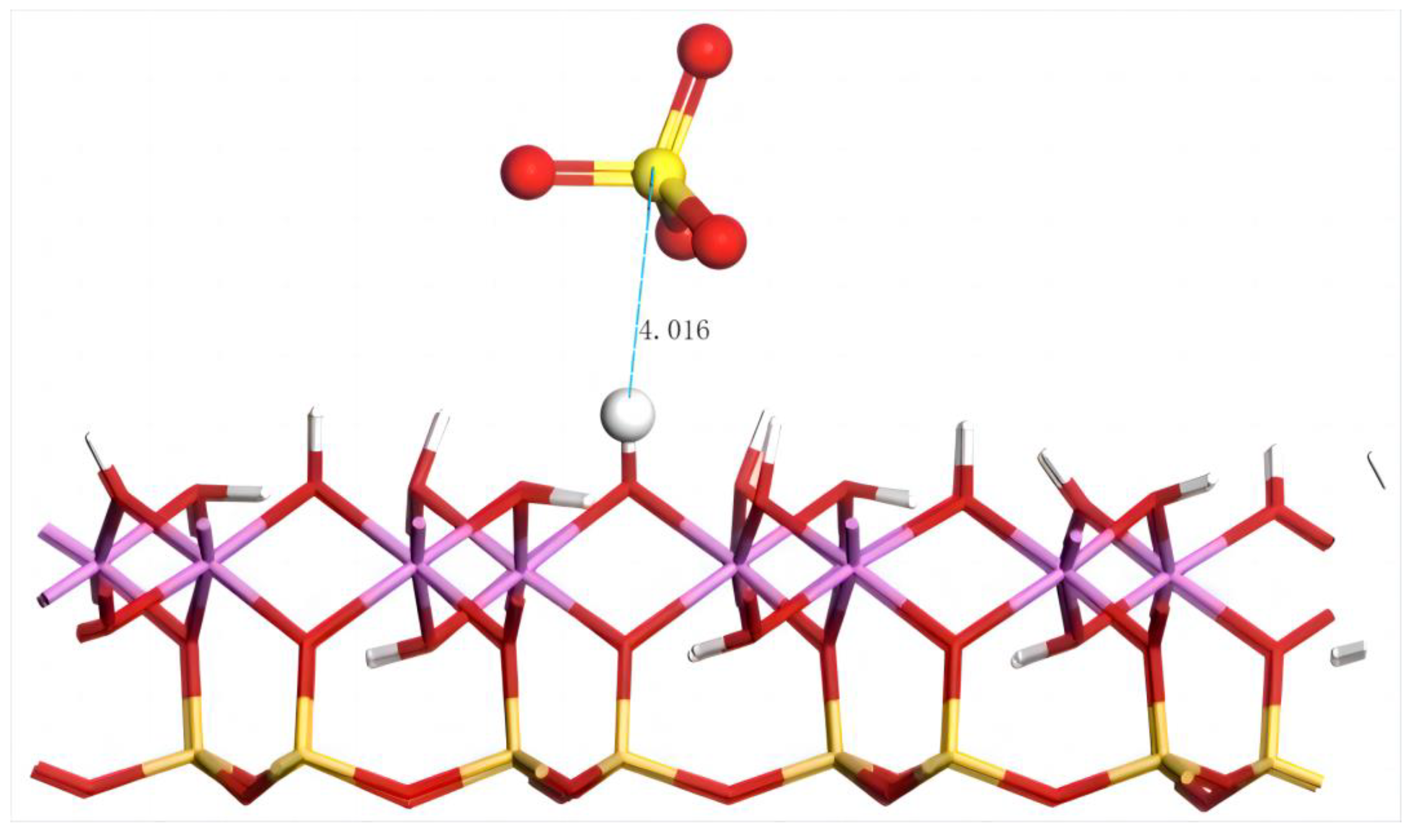
4.4.2. Adsorption of SO42− on the Silico–Oxygen Plane of Kaolinite
4.5. Adsorption of MgSO4 on the Aluminum–Hydroxyl Plane of Kaolinite
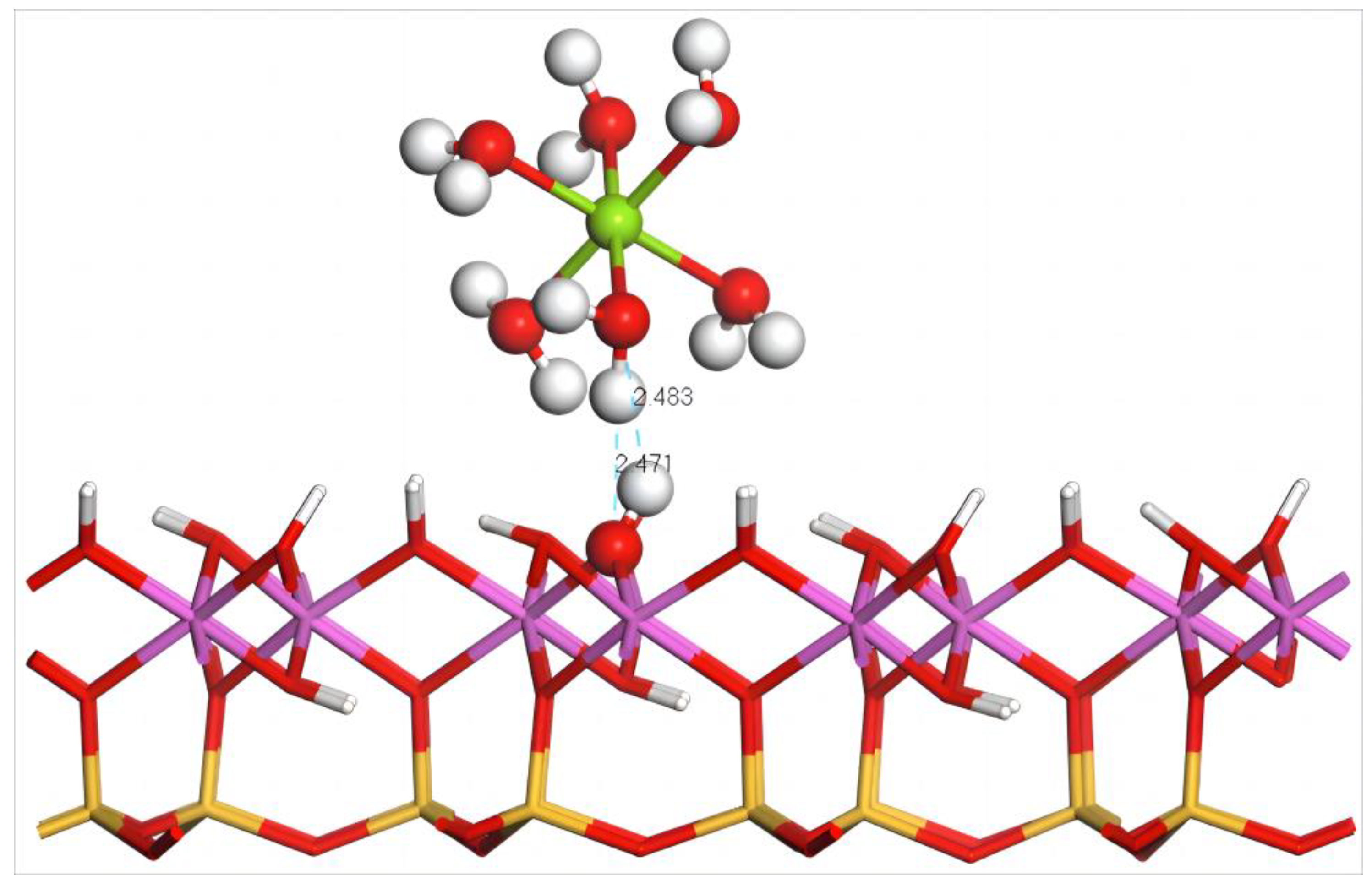
4.5.1. Adsorption of Mg(H2O)62+ on the Aluminum–Hydroxyl Plane of Kaolinite
- (1)
- Adsorption Configuration and Adsorption Energy
- (2)
- Electron Transfer and State Density Study
4.5.2. Adsorption of SO42− on the Aluminum–Hydroxyl Plane of Kaolinite
5. Conclusions
Author Contributions
Funding
Data Availability Statement
Acknowledgments
Conflicts of Interest
References
- Brown, B.; Ma, B.M.; Chen, Z.M. Developments in the processing and properties of NdFeb-type permanent magnets. J. Magn. Magn. Mater. 2002, 248, 432–440. [Google Scholar] [CrossRef]
- Zeng, S.H.; Du, D.P.; Bai, F.H.; Su, H.Q. Bridging complexes of rare earth and cobalt cluster as catalyst precursors for Fischer-Tropsch synthesis. J. Rare Earths 2011, 29, 349–353. [Google Scholar] [CrossRef]
- Chen, H.; Wang, Y.H. Photoluminescence and cathodoluminescence properties of novel rare-earth free narrow-band bright green-emitting ZnB2O4:Mn2+ phosphor for LEDs and FEDs. Chem. Eng. J. 2019, 361, 314–321. [Google Scholar] [CrossRef]
- Huang, L.J.H.; Xiao, B.; Liu, L.H.; Li, W.H.; Duan, X.G.; Huang, W.F.; Fan, C.Y.; Dong, Y.; Liu, S.M. Selective recovery of Gd(III) by benzimidazole- and benzoxazole-linked 3D porous polymers. J. Water Process Eng. 2023, 51, 103378. [Google Scholar] [CrossRef]
- Huang, W.F.; Zou, Z.Q.; Zhong, X.X.; Huang, X.L. Occurrence characteristics and leaching rules of different weathering rare earth ores. J. Chin. Soc. Rare Earths 2017, 35, 253–261. [Google Scholar]
- Huang, L.J.H.; Liu, H.L.; Huang, W.F.; Zhao, B.X.; Shen, Z.F.; Bao, Y.Q. Recovery of lanthanum cations by functionalized magnetic multi-walled carbon nanotube bundles. RSC Adv. 2021, 11, 4751–4759. [Google Scholar] [CrossRef]
- Xiao, Y.F.; Chen, Y.Y.; Feng, Z.Y.; Huang, X.W.; Huang, L.J.H.; Long, Z.Q.; Cui, D.L. Leaching characteristics of ion-adsorption type rare earths ore with magnesium sulfate. Nonferr. Metal. Soc. 2015, 25, 3784–3790. [Google Scholar] [CrossRef]
- Xiao, Y.F.; Feng, Z.Y.; Huang, X.W.; Huang, L.J.H.; Chen, Y.Y.; Wang, L.S.; Long, Z.Q. Recovery of rare earths from weathered crust elution-deposited rare earth ore without ammonia-nitrogen pollution: I. leaching with magnesium sulfate. Hydrometallurgy 2015, 153, 58–65. [Google Scholar]
- He, Z.Y.; Zhang, Z.Y.; Yu, J.X.; Xu, Z.G.; Xu, Y.L.; Zhou, F.; Chi, R.A. Column leaching process of rare earth and aluminum from weathered crust elution-deposited rare earth ore with ammonium salts. Trans. Nonferrous Met. Soc. China 2016, 26, 3024–3033. [Google Scholar] [CrossRef]
- Wu, P.Q.; Zhou, J.W.; Huang, J.; Lin, X.J.; Liang, X.L. Enrichment and fractionation of rare earth elements in ion-adsorption rare earth elements deposits: Constraints of iron oxide-clay mineral composites. Geochimica 2022, 51, 271–282. [Google Scholar]
- Zhang, M.; He, X.C.; Tan, W.; Ma, L.Y.; Zhao, F.F. Geochemical characteristics and genesis of ion-adsorption type REE deposit in the Lincang granite, Yunnan Province. Geol. China 2022, 49, 201–214. [Google Scholar]
- Liu, E.H.; Huang, J.; Tan, W.; Liang, X.L.; Ma, L.Y. Constraints on the Ree enrichment-fractionation in weathering crust by the mineral evolution in the weathering and leaching processes: A case study of the Renju Ree deposit in the Meizhou Area, Guangdong, China. Bull. Mineral. Petrol. Geochem. 2022, 41, 517–526. [Google Scholar]
- Zai, X.S.; Li, J.P.; Xin, J.Z.; Fang, Z.J.; Mo, J.C. Detection and finite element analysis for a stone arch bridge. J. Guangxi Univ. Sci. Technol. 2016, 27, 66–70. [Google Scholar]
- Ning, L.; Gou, K.Y.; Liu, M.L.; Zeng, J.S.; Lu, Y.; Zhou, X.; Fang, Z.J. Clay mineral montmorillonite crystals and their structural analysis. J. Guangxi Univ. Sci. Technol. 2020, 31, 75–81. [Google Scholar]
- Yao, X.H.; Huang, L.J.H.; Huang, W.F.; Zeng, X.R.; Huang, B.L.; Bao, Y.Q. Density functional calculation of La(H2O)3+10 adsorption on surface of montmorillonite (001). Bull. Chin. Ceram. Soc. 2021, 40, 3769–3776. [Google Scholar]
- Du, J.; Min, F.F.; Zhang, M.X.; Peng, C.L.; Fang, F. Adsorption of H3O+ on (001) basal and (010) edge surface of illite: A DFT study. J. China Coal Soc. 2018, 43, 2625–2632. [Google Scholar]
- Zou, Z.Q.; Huang, L.J.H.; Li, X.D.; Xu, J.; Zeng, X.R.; Shu, R.H.; Xiao, B.; Ou, J.C.; Huang, W.F. Adsorption of Hydrated Pr3+ and NH4+/Mg2+ Ions onto the (001) Surface of Montmorillonite: A DFT Analysis with Experimental Verification. Minerals 2022, 12, 1454. [Google Scholar] [CrossRef]
- Weshahy, A.R.; Gouda, A.A.; Atia, B.M.; Sakr, A.K.; Al-Otaibi, J.S.; Almuqrin, A.; Hanfi, M.Y.; Sayyed, M.I.; El Sheikh, R.; Radwan, H.A.; et al. Efficient recovery of rare earth elements and zinc from spent Ni-metal hydride batteries: Statistical studies. Nanomaterials 2022, 12, 2305. [Google Scholar] [CrossRef]
- Allam, E.M.; Lashen, T.A.; Abou El-Enein, S.A.; Hassanin, M.A.; Sakr, A.K.; Cheira, M.F.; Almuqrin, A.; Hanfi, M.Y.; Sayyed, M.I. Rare earth group separation after extraction using sodium diethyldithiocarbamate/polyvinyl chloride from lamprophyre dykes leachate. Materials 2022, 15, 1211. [Google Scholar] [CrossRef]
- Lee, S.G.; Choi, J.I.; Koh, W.; Jang, S.S. Adsorption of β-d-glucose and cellobiose on kaolinite surfaces: Density functional theory (DFT) approach. Appl. Clay Sci. 2013, 71, 73–81. [Google Scholar] [CrossRef]
- Qiu, S.; Yan, H.; Qiu, X.; Wu, H.; Zhou, X.; Wu, H.; Li, X.; Qiu, T. Adsorption of La on kaolinite (001) surface in aqueous system: A combined simulation with an experimental verification. J. Mol. Liq. 2021, 347, 117956. [Google Scholar] [CrossRef]
- Chen, J.; Min, F.F.; Liu, L.Y.; Jia, F.F. Adsorption of methylamine cations on kaolinite basal surfaces: A DFT study. Physicochem. Probl. Miner. Process. 2020, 56, 338–349. [Google Scholar] [CrossRef]
- Chen, J.; Min, F.F.; Liu, L.Y.; Liu, C.F. Mechanism research on surface hydration of kaolinite, insights from DFT and MD simulations. Appl. Surf. Sci. 2019, 476, 6–15. [Google Scholar] [CrossRef]
- Chen, J.; Min, F.F.; Liu, L.Y. The interactions between fine particles of coal and kaolinite in aqueous, insights from experiments and molecular simulations. Appl. Surf. Sci. 2019, 467, 12–21. [Google Scholar] [CrossRef]
- Patrick, V.B.; Randall, T.C.; Kathryn, L.N. Molecular controls on kaolinite surface charge. J. Colloid Interface Sci. 1996, 183, 356–364. [Google Scholar]
- Heimann, J.E.; Grimes, R.T.; Rosenzweig, Z.; Bennett, J.W. A density functional theory (DFT) investigation of how small molecules and atmospheric pollutants relevant to art conservation adsorb on kaolinite. Appl. Clay Sci. 2021, 206, 106075. [Google Scholar] [CrossRef]
- Li, M.L.; Wang, X.P.; Zhang, J.; Gao, Y.H.; Zhang, W. Cu-loaded MOF-303 for iodine adsorption: The roles of Cu species and pyrazole ligands. Appl. Surf. Sci. 2023, 619, 156819. [Google Scholar] [CrossRef]
- Zhang, W.; Zhang, J.; Dong, X.T.; Li, M.L.; He, Q.; Zhao, S.; Xie, L.X. Fluorinated metal–organic frameworks for enhanced stability and iodine adsorption selectivity under humid conditions. Chem. Eng. J. 2023, 461, 142058. [Google Scholar] [CrossRef]
- Zeng, X.R.; Zeng, B.; Huang, L.J.H.; Zhong, L.; Li, X.D.; Huang, W.F. Adsorption of Y(III) on the Interface of Kaolinite-H2O: A DFT Study. Minerals 2022, 12, 1128. [Google Scholar] [CrossRef]
- Xu, H.Y.; Guan, D.Q.; Ma, L. The bio-inspired heterogeneous single-cluster catalyst Ni100-Fe4S4 for enhanced electrochemical CO2 reduction to CH4. Nanoscale 2023, 15, 2756–2766. [Google Scholar] [CrossRef]
- Xiao, W.; Kiran, G.K.; Yoo, K.; Kim, J.-H.; Xu, H.Y. The dual-site adsorption and high redox activity enabled by hybrid organic-inorganic vanadyl ethylene glycolate for high-rate and long-durability lithium-sulfur batteries. Small 2023, 19, 2206750. [Google Scholar] [CrossRef]
- Xu, H.Y.; Guan, D.Q. Exceptional anisotropic noncovalent interactions in ultrathin nanorods: The terminal sigma-hole. ACS Appl. Mater. Interfaces 2022, 14, 51190–51199. [Google Scholar] [CrossRef]
- Zhang, Z.J.; Zhou, Q.; Yuan, Z.T.; Zhao, L.; Dong, J.D. Adsorption of Mg2+ and K+ on the kaolinite (001) surface in aqueous system: A combined DFT and AIMD study with an experimental verification. Appl. Surf. Sci. 2021, 538, 148158. [Google Scholar] [CrossRef]


| N | Rmin/Å | Rmax/Å | Rmean/Å | Ebinding/kJ·mol−1 | Dy Charge/e |
|---|---|---|---|---|---|
| 6 | 2.29 | 2.434 | 2.34467 | −1206.7 | 2.02 |
| 7 | 2.328 | 2.434 | 2.39043 | −1361.8 | 2.01 |
| 8 | 2.385 | 2.487 | 2.42225 | −1478.4 | 2.01 |
| 9 | 2.375 | 2.715 | 2.46822 | −1545.6 | 2.02 |
| 10 | 2.428 | 2.643 | 2.5184 | −2403.8 | 2.08 |
| Atom | n | s | p | d | f | Total | Charge/e |
|---|---|---|---|---|---|---|---|
| O | 1 | 1.86 | 5.08 | 0 | 0 | 6.94 | −0.94 |
| O | 2 | 1.87 | 5.09 | 0 | 0 | 6.96 | −0.96 |
| O | 3 | 1.86 | 5.07 | 0 | 0 | 6.93 | −0.93 |
| O | 4 | 1.87 | 5.10 | 0 | 0 | 6.98 | −0.98 |
| O | 5 | 1.86 | 5.06 | 0 | 0 | 6.92 | −0.92 |
| O | 6 | 1.86 | 5.07 | 0 | 0 | 6.93 | −0.93 |
| O | 7 | 1.86 | 5.06 | 0 | 0 | 6.92 | −0.92 |
| O | 8 | 1.86 | 5.07 | 0 | 0 | 6.93 | −0.93 |
| O | 9 | 1.86 | 5.07 | 0 | 0 | 6.93 | −0.93 |
| O | 10 | 1.86 | 5.06 | 0 | 0 | 6.92 | −0.92 |
| Dy | 1 | 2.19 | 5.72 | 0.70 | 9.17 | 17.78 | 2.22 |
| Bond | PopulationValue | Length |
|---|---|---|
| Dy–O1 | 0.12 | 2.50 |
| Dy–O2 | 0.12 | 2.57 |
| Dy–O3 | 0.11 | 2.43 |
| Dy–O4 | 0.14 | 2.59 |
| Dy–O5 | 0.13 | 2.47 |
| Dy–O6 | 0.12 | 2.54 |
| Dy–O7 | 0.11 | 2.45 |
| Dy–O8 | 0.11 | 2.47 |
| Dy–O9 | 0.13 | 2.51 |
| Dy–O10 | 0.13 | 2.64 |
| Structure | N | Dy–O/Å | Dy–Om/Å | Eads/kJ·mol−1 |
|---|---|---|---|---|
| Before | 10 | 2.58, 2.58, 2.58, 2.58, and 2.58 2.58, 2.58, 2.58, 2.58, and 2.58 | 2.58 | −544.3 |
| After | 10 | 2.47, 2.51, 2.45, 2.64, and 2.43 2.57, 2.59, 2.50, 2.55, and 2.47 | 2.51 |
| Element | s | p | d | f | Total | Charge/e |
|---|---|---|---|---|---|---|
| Dy before | 2.17 | 5.65 | 0.62 | 9.74 | 18.19 | 1.81 |
| Dy after | 2.18 | 5.71 | 0.72 | 9.4 | 18.01 | 1.99 |
| Structure | N | Dy–O/Å | Dy–Om/Å | Eads/kJ·mol−1 |
|---|---|---|---|---|
| Before | 10 | 2.58, 2.58, 2.58, 2.58, and 2.58 2.58, 2.58, 2.58, 2.58, and 2.58 | 2.58 | −194.4 |
| After | 10 | 2.58, 2.59, 2.58, 2.58, and 2.58 2.59, 2.58, 2.58, 2.59, and 2.58 | 2.583 |
| Atom | s | p | d | f | Total | Charge/e |
|---|---|---|---|---|---|---|
| Dy before | 2.17 | 5.65 | 0.62 | 9.74 | 18.19 | 1.81 |
| Dy after | 2.18 | 5.89 | 0.37 | 9.01 | 17.45 | 2.55 |
| Structure | N | Mg–O/Å | Mg–Om/Å | Eads/kJ·mol−1 |
|---|---|---|---|---|
| Before | 6 | 2.26, 2.26, and 2.26 2.26, 2.26, and 2.26 | 2.26 | −230.4 |
| After | 6 | 2.39, 2.53, and 2.57 2.48, 2.61, and 2.56 | 2.52 |
| Atom | s | p | d | f | Total | Charge/e |
|---|---|---|---|---|---|---|
| Mg before | 0.33 | 5.99 | 0 | 0 | 6.32 | 1.68 |
| Mg after | 0.29 | 5.89 | 0 | 0 | 6.18 | 1.82 |
| Structure | N | Mg–O/Å | Mg–Om/Å | Eads/kJ·mol−1 |
|---|---|---|---|---|
| Before | 6 | 2.26, 2.26, and 2.26 2.26, 2.26, and 2.26 | 2.26 | −180.5 |
| After | 6 | 2.43, 2.45, and 2.33 2.46, 2.30, and 2.58 | 2.43 |
| Atom | s | p | d | f | Total | Charge/e |
|---|---|---|---|---|---|---|
| Mg before | 0.33 | 5.99 | 0 | 0 | 6.32 | 1.68 |
| Mg after | 0.26 | 5.88 | 0 | 0 | 6.15 | 1.85 |
Disclaimer/Publisher’s Note: The statements, opinions and data contained in all publications are solely those of the individual author(s) and contributor(s) and not of MDPI and/or the editor(s). MDPI and/or the editor(s) disclaim responsibility for any injury to people or property resulting from any ideas, methods, instructions or products referred to in the content. |
© 2023 by the authors. Licensee MDPI, Basel, Switzerland. This article is an open access article distributed under the terms and conditions of the Creative Commons Attribution (CC BY) license (https://creativecommons.org/licenses/by/4.0/).
Share and Cite
Huang, L.; Zou, Z.; Liu, S.; Liu, L.; Xiao, W.; Qian, Y.; Alam, S.; Huang, W. Investigation of Hydrated Dy(III) and MgSO4 Leaching Agent Ion Adsorption on (001) Surface of Montmorillonite: A Study Using Density Functional Theory. Minerals 2023, 13, 831. https://doi.org/10.3390/min13060831
Huang L, Zou Z, Liu S, Liu L, Xiao W, Qian Y, Alam S, Huang W. Investigation of Hydrated Dy(III) and MgSO4 Leaching Agent Ion Adsorption on (001) Surface of Montmorillonite: A Study Using Density Functional Theory. Minerals. 2023; 13(6):831. https://doi.org/10.3390/min13060831
Chicago/Turabian StyleHuang, Lijinhong, Zhiqiang Zou, Shaomin Liu, Lihong Liu, Wengang Xiao, Yantao Qian, Shafiq Alam, and Wanfu Huang. 2023. "Investigation of Hydrated Dy(III) and MgSO4 Leaching Agent Ion Adsorption on (001) Surface of Montmorillonite: A Study Using Density Functional Theory" Minerals 13, no. 6: 831. https://doi.org/10.3390/min13060831
APA StyleHuang, L., Zou, Z., Liu, S., Liu, L., Xiao, W., Qian, Y., Alam, S., & Huang, W. (2023). Investigation of Hydrated Dy(III) and MgSO4 Leaching Agent Ion Adsorption on (001) Surface of Montmorillonite: A Study Using Density Functional Theory. Minerals, 13(6), 831. https://doi.org/10.3390/min13060831