Abstract
This study investigated the micro and nanoscale structure in Cu-Zn alloy, as well as its corrosion patterns. To achieve this goal, a set of Roman orichalcum coins were analysed using Scanning Electron Microscopy (SEM-EDS), X-ray maps, high resolution field emission scanning electron microscopy (HR-FESEM-EDS) and electron microprobe analyser (EMPA) techniques. The samples showed a high degree of corrosion on their external surfaces, which evolved in depth up to ~1 mm. Micro and sub-micro imaging of the inner metal highlighted the presence of “stressed areas” caused by mechanical processing work, representing the trigger zone of corrosion and causing the loss of material. These images also permitted us to follow the grain-grain interface and selective Zn-dealloying in the examined samples. X-ray maps of Cu and Zn helped us to understand the evolution of the dezincification process, from rim to core. HR-FESEM-EDS imaging investigation highlighted a heterogeneous composition within the strain line structures, confirming that the mechanically stressed areas were active zones for corrosion processes. Cracks and voids also characterised the patina. Conversely, the uncorroded cores of the samples were not affected by dealloying.
1. Introduction
Cu-Zn alloy is considered a good industrial material, due to its high strength, formability and remarkable corrosion resistance. Indeed, it is used in the production of electrical conductors, connectors, lead frames, and in many other applications [1,2]. Nevertheless, over time corrosion processes affect metals and alloys, generating serious problems for industrial materials, as well as for archaeological artefacts [3,4,5,6]. The negative impact of corrosion on the conservation of private and museum collections justifies great technological and scientific endeavour in the study of metal deterioration. [7,8,9,10]. In this context, significant efforts have been made to understand, predict and prevent corrosion [11,12,13]. This phenomenon is generally explained by the formation of corrosion at the metal–electrolyte interface [14], which involves the loss of material, highlighted by the presence of pitting areas.
Accelerated corrosion studies are usually carried out in a laboratory, simulating the environmental conditions of burial as much as possible [15]. However, laboratory simulations do not take into account important factors, such as mechanical stress affecting artefacts, which undergo a production phase and random environmental variations that can occur during long periods of burial history. Indeed, the study of ancient alloys permits the evaluation of metal behaviours and corrosive processes in different burial environments [8,16,17,18,19]. Experimental studies on the long-term corrosion mechanism of alloys at the micro and nanoscales, and the distribution of damage, represent one of the major challenges that must be addressed to protect archaeological objects [7].
In recent years, several advances in sub-micro and nanoscale studies have impacted industry and the diagnostics applied to cultural heritage [20,21,22], whereas research applied to archaeological metal artefacts has been very limited [23,24]. Previous research has shown that non-invasive and micro-destructive analyses on archaeological metal samples are useful tools to acquire qualitative information about the surface, the patina and the corrosion processes [9,25,26]. However, these kinds of measurement can be influenced by several factors, which may increase errors in results. In the particular case of orichalcum, archaeological samples suffer from dealloying of the patinas, i.e., dezincification (the loss of zinc) or, in the worst cases, decuprification (the subsequent loss of copper). Such processes cause the formation of a porous patina that can exceed a millimetre of depth, and which is different in composition and structure from the uncorroded inner core of the object [26]. Therefore, surface techniques have to be used with caution, especially in the case of determining the composition of ancient alloys, because the techniques generally do not allow the acquiring of information from a depth greater than 20–30 µm [27].
Recently, surface analyses on archaeological samples [9,18,19,25,26,28,29,30] revealed the importance of studying the development of corrosion in ancient alloys. The progression of the corrosion in archaeological metallic artefacts is strictly related to their conservation. Research on corrosion mechanisms of historical alloys can help the development of suitable protective coatings for metals. These coatings can help improve the condition of metal preservation by reducing the corrosion rate, but they do not stop these processes [31,32]. For these reasons, investigation at high resolution (from micro to nanoscale) of the corrosion mechanism can support research into improving and producing ever more specific protective products. Moreover, this information can provide suggestions for museum conservators and private collectors as to how they can minimize the degradation damage by selecting dedicated protective coatings, that take into account environmental conditions of the museum/gallery and intrinsic properties of the object under question. Furthermore, the results can drive decisions about the selection of the most suitable and less aggressive chemical solutions for cleaning, conservation and restorative treatments to safeguard collections [33]. Archaeometric studies of ancient coins [9,27,28,29,34,35,36] are a powerful tool to enhance knowledge on the processing and use of metals, development of coinage methods and economic circulation in different historical periods.
Moreover, the study of ancient alloys permits the evaluation of metal behaviours and corrosive processes in different burial environments [8,16,17,18,19,37]. All the information obtained by archaeometric investigations can give useful suggestions for the conservation and preservation of metal finds in the future [11,30,38].
The current work aimed at investigating the effect of corrosion on a set of coins over centuries, assessing the micro and nanostructures and gaining understanding of the evolution of the dezincification process. Indeed, the variations in microstructure and texture induced selective corrosion and gradual dealloying. Here, the micro to sub-micro scale corrosion process of Cu-Zn-based alloy was explored. The use of a high resolution scanning electron microscope (HR-FESEM-EDS), combined with X-ray elemental mapping, provided information about the chemical composition of the unaltered alloy at micro and sub-micro scale, and allowed determination of the degree of corrosion of the samples and, consequently, their state of preservation. The specific objectives were the investigation of changes in morphology, changes in composition due to the corrosive process, porosity of the alloy and its influence on corrosion. With a multi-analytical approach an attempt was made to identify which structural elements affected the corrosion process. The results were also compared with data from literature [15,39].
For the first time, coins minted in orichalcum were analysed using high resolution imaging, appreciating the microstructures of the alloy in greater detail. It was also possible to learn about the specific composition of very small sections of the Cu-Zn-based alloy.
This study provided an exceptional opportunity to examine at high magnification the inner core of ancient metal objects. The investigation of the structures of the orichalcum allowed a better understanding of the cementation process, i.e., the metallurgical process adopted and improved by Romans [40,41] to produce the Cu-Zn alloy. Roman coins can suffer from a high degree of corrosion, not only on their superficial patinas, but also in the inner areas [26]. Therefore, the examination of the structures with high resolution imaging permitted the understanding of where the corrosive processes started in this ancient alloy artefact.
2. Materials and Methods
2.1. Materials
A selected number of samples were analysed from private collections, which were cut in order to better understand the corrosion processes of ancient orichalcum by investigating the microstructures of the orichalcum alloy and the degradation of the patina formed by the natural degradation processes. Due to the difficulty of obtaining permission to study archaeological samples in a destructive way, a limited number of Roman coins (A3, F1, F13, F14) were explored in this study (Figure 1). All the samples appeared gold-like in colour, typical of objects in orichalcum. The dimension of the samples was very variable. The thickness of the samples was ~2 mm for samples A3 and F1, and ~1 mm for samples F13 and F14. Nevertheless, the thickness of each sample was variable due to the minting process and degradation. For historical and numismatic information see Figure 1. Despite the small number of samples, this study provided technical insights on archaeological corroded objects, while expanding the results of previous research endeavours [26].
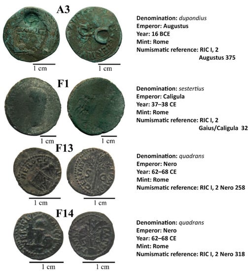
Figure 1.
Images of the studied coins (reverse and obverse), from private collections, and their numismatic information.
Numismatic overview [42] revealed that the denominations were one dupondius, one sestertius and two quadrantes issued under the reign of Augustus (27 BCE–14 CE), Caius (37–41 CE) and Nero (54–68 CE). In particular, the samples A3 and F1 were minted during the Augustus and Caius Empires, respectively, following the rules of the Augustus monetary reform (23 BCE), whereas samples F13 and F14 were produced under Nero, after his monetary reform of 63–64 CE [43,44].
2.2. Methods
To explore and characterize the nature of the alloy and its corrosion pattern, it was necessary to prepare cross sections, cutting the coins from rim to rim. Then, the sections were embedded in epoxy resins, using appropriate moulds, and polished.
Scanning electron microscope (SEM-EDS (Department of Earth Sciences, Sapienza University of Rome, Italy) investigations were performed on the cross sections (from rim to core to rim), using a FEI-Quanta 400 instrument with an EDAX Genesis Microanalysis system. Secondary electron (SE) and back-scattered electron (BSE) imaging, along with X-ray maps, were carried out to study the microstructure of the alloy and to evaluate the evolution of the corrosion process inside archaeological samples.
The investigation at high magnification was performed on the same cross section by means of an AURIGA Zeiss High Resolution Field Emission Scanning Electron Microscope (HR-FESEM, SNN-lab at Center for Nanotechnology for Engineering-CNIS, Sapienza University of Rome) equipped with a Bruker energy dispersive X-ray spectroscopy (EDS) system. BSE imaging and X-ray maps were realized to obtain precision qualitative data on corroded areas. HR-FESEM offers high magnification imaging that provides the characterization of corrosion pattern at sub-micrometre scale, allowing also semi-quantitative EDS analyses.
EMPA measurements for quantitative chemical analyses were performed using a Cameca SX50 electron microprobe equipped with five wavelength-dispersive spectrometers (CNR–IGAG, Rome, c/o Department of Earth Sciences, Sapienza University of Rome). The accelerating voltage was 15 kV, and beam current 15 nA. Element peaks and background were measured with counting times of 20 and 10 s, respectively. Metallic Cu and metallic Zn were used, respectively, as a reference standard for Cu and Zn (LIF). Matrix corrections were calculated by the PAP method [45], with software supplied by Microbeams Services. The detection limits under the specified working condition varied from 0.05 to 0.1 wt.% with standard deviations from 0.02 to 0.04 wt.%. The analytical error was ∼1% rel. for the major elements. During EMPA measurements, only the chemical elements that could make up the alloy were taken into consideration, in order to discover the real composition of the ancient orichalcum. For this purpose, analyses of altered areas of the samples did not use reference standards of exogenous elements (such as Mg, Al, Si, Cl, K, Ca).
3. Results
The analysis of the microstructures and corrosion layers of brass coins allows evaluation of the degree of corrosion and its dependence from mechanically stressed areas. The study on natural corrosion of ancient coins, developed in depth over the years, explores both the alloy microstructures and the corrosion structures at high magnification, without resorting to etching treatment.
The sestertius F1 showed a complex corrosion pattern from core to rim (Figure 2) due to its severe condition after issuing and circulation. Considering a ~2 mm average thickness of the specimen, the uncorroded nucleus had a maximum breadth of ~1.2 mm and a minimum of ~200 µm, whereas the corroded layer varied from ~400 µm up to ~1 mm in depth (Figure 2a). The corroded external layer was formed by a porous microstructure, increasing from the inner nucleus to the external rim. In particular, it was evident that the grain-grain interface (Figure 2c,d) played an important role in triggering corrosion, as evidenced by the selective corrosion of grains that highlighted the grain boundaries. Moreover, back-scattered images showed the presence of fine and parallel strain lines caused by plastic deformation, especially in the proximity of the external corroded layer of the sample (Figure 2b). These line structures, usually occurring after chemical etching treatments in a laboratory, involved natural degradation processes and selective depletion of the stressed areas, as evidenced by the dark grey colour. Indeed, HR-FESEM images of these structures at higher magnification showed several intersections between bundles of lines (Figure 3). The analysis highlighted that the fine strain lines were not continuous, unlike what had been previously observed. Indeed, at the perpendicular intersections of two bundles of parallel lines, single cross-shaped sub-micro domains with a homogeneous composition were formed (Figure 3d). In some cases, the corroded spots forming the strain lines could be smaller than a micron (Figure 3). In addition, sample F1 showed evidences of corrosion with a consequent dezincification that followed the grain boundaries (Figure 2c,d). Figure 2d shows the α-brass structures as highlighted by the occurrence of microdomains around the grains of the alloy [46]. The microstructures observed at high magnification were indirectly Cu-enriched areas, due to corrosion of Zn and selective de-alloying. This difference in chemical composition, compared to the undegraded alloy of the sample, was confirmed through microanalysis (Figure 4). Indeed, the EDS spectrum of the altered micro-domains showed oxygen and copper signals, suggesting the presence of copper oxides. Moreover, the absence of zinc could be noticed, which caused the indirect Cu-enrichment of the degraded areas. Conversely, the EDS spectrum of the unaltered metal presents the typical composition of the orichalcum alloy [46].
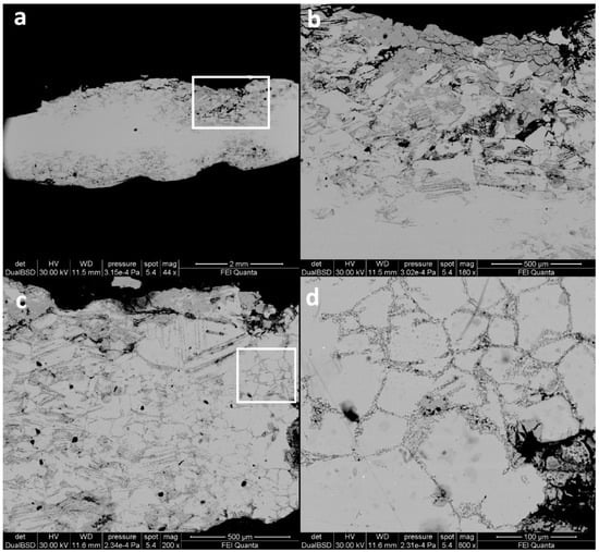
Figure 2.
BSE images of cross section of sample F1. Here the corrosion patterns are well visible through the whole section. Moreover, in (b,c) the fine and parallel strain lines caused by plastic deformation are clearly visible, especially in proximity of the external corroded layer. Evidence of corrosion, with consequent dezincification following the grain boundaries, is visible (c,d). From (a–d) the magnification is increased: the highlighted area in (a) is expanded in (b,c), the highlighted area in (c) is expanded in (d).
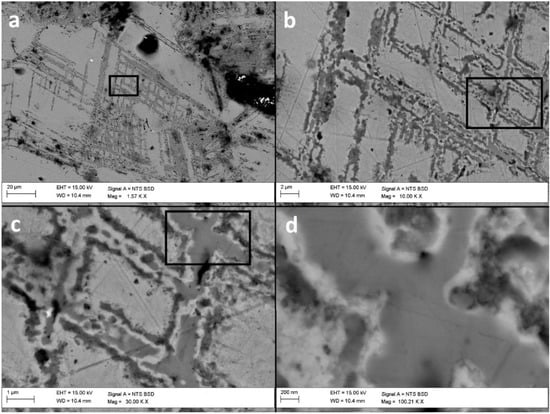
Figure 3.
BSE images at sub-micro scale of cross section of sample F1. At high magnification several intersections between bundles of lines are clearly visible. The fine strain lines are not continuous and at the perpendicular intersections of two bundles of parallel lines, single cross-shaped sub-micro domains are formed (c,d). The corrosion could be smaller than a micron (d). From (a–d) the magnification is increased: the highlighted area in (a) is expanded in (b), the highlighted area in (b) is expanded in (c), the highlighted area in (c) is expanded in (d).
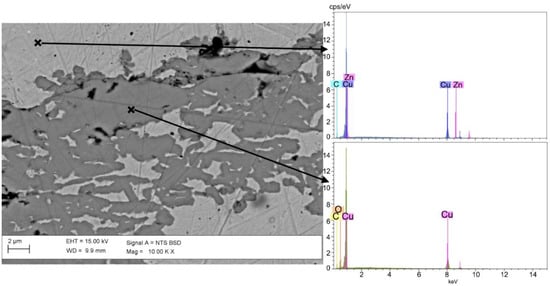
Figure 4.
BSE image at sub-micro scale of cross section of sample F1 and related EDS spectra of unaltered and altered areas. It can be seen that in degraded areas zinc is totally absent and dezincification has completely occurred.
Zinc depletion could also be clearly observed in the patina layer, corresponding to the external portion of the dupondius and the sestertius. In sample A3 (the dupondius, Figure 5) the degraded patina had an average extension in depth of ~350 µm, reaching a maximum of ~500 µm. In this area, the X-ray elemental distribution maps of sample A3 (Figure 5) showed a lower amount of Zn for the entire thickness of the patina, when compared to the innermost portion of the sample. The distribution of Cu was homogeneous, both in the patina and in the core of the sample, excluding the areas where the leaching of Cu caused porosity of the metal. Moreover, X-ray maps highlighted the presence of Cl in the section. Chlorine was concentrated in the area corresponding to the patina-core interface. Its distribution matched with the more degraded zones, as shown by the BSE image (Figure 5), and the Zn-depleted areas at the patina–core interface. The presence of both Cu and Cl in the degraded area, as underlined by X-ray maps, could suggest the occurrence of basic copper (II) chloride of stoichiometry Cu2Cl(OH) as botallackite, atacamite, paratacamite and clinoatacamite [47].
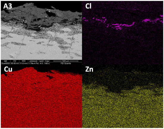
Figure 5.
BSE images in cross section of sample A3 and related X-ray maps of Cl, Cu and Zn. The maps highlighted the presence of Cl at the interface between the patina and the unaltered core, as well as the dezincification of the outer layer of the coin A3.
The quadrantes F13 and F14 have Zn-depleted patinas like the sestertius and the dupondius. EDS analyses revealed a low presence of Zn and Cu in the external layer of these coins (Figure 6). In particular, in the sample F13 a homogeneous patina of ~60 µm occurred (Figure 6b). The patina appeared to be compact and with a very low degree of porosity. EDS analyses of the patina in section (Figure 6c–e) revealed that a dezincification process occurred in the external area, whereas in the inner area Zn was still present (Figure 6b,e). In addition, the patina of sample F13 appeared to have exogenous elements in it, coming from the burial soil, such as Mg, Al, P, K, Ca, Fe. In particular, the Si peak, also present in sample F14, was very intense (Figure 6c,d). In both samples, the EDS analyses carried out on several points of the patina, the patina-core interface and the core itself excluded the presence of chlorine.
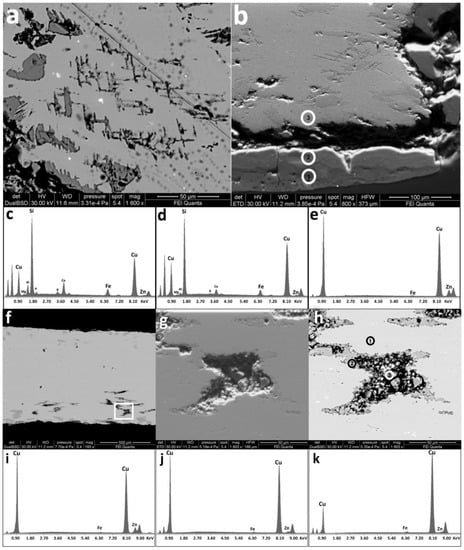
Figure 6.
SEM images of the lower edge of sample F13 and relative spectra. In particular, a homogeneous and compact patina of ~60 µm occurred (b). EDS analyses (c–e) revealed that a dezincification process had occurred on the external area, whereas in the inner area Zn was still present. In addition, exogenous elements were in it. Porosity was also present near the edge (f–h). BSE (a) and SE (b) high magnification images of sample F13; (c) EDS spectrum of point “1” in image (b); (d) EDS spectrum of point “2” in image (b); (e) EDS spectrum of point “3” in image (b); (f) BSE cross section images of sample F13, the highlighted area in (f) is expanded in (g) SE image and (h) BSE image. EDS spectra from (i–k) are related to points 1, 2 and 3 respectively, highlighted in (h).
At high magnification, SEM imaging showed a detachment between the uncorroded core and the patina of the quadrantes (Figure 6a,b). In the case of samples F13 and F14 the corrosion process had occurred (Figure 6i–k). In Figure 6f–h the existence of porosity in the lower area of the section is visible, decreasing through the core of the sample. The holes were stretched horizontally and showed a coalescence process caused by the progress of corrosion.
The unaltered metallic area (Figure 6h point 1) presented the typical orichalcum composition, i.e. a Cu-Zn alloy (Figure 6i), whereas the edge of the degraded zone (Figure 6h point 2) had a chemical composition that led to the dezincification process (Figure 6j), in which the EDS analyses showed the decrease of Zn, compared to the standard brass spectrum. Finally, the Zn signal was extremely weak in the inner part of the degraded area and the Cu signal had a lower intensity than the other spectra (Figure 6h point 3, Figure 6k).
BSE images of quadrantes F13 and F14 showed the presence of fine and parallel strain lines, representing the plastic deformation signs (Figure 7), with a high level of corrosion. EDS spectra of Figure 7 reveal Zn depletion. HR-FESEM-EDS investigation of the line structures at sub-micro scale showed similarities between quadrantes (Figure 7) and sample F1 (Figure 3). The dezincification process, as shown in the HR-FESEM images, followed the stress lines and the grain boundaries of the alloy. Indeed, EDS analyses on samples F13 and F14 showed that in the lines a dezincification process had occurred and a progressive loss of copper was taking place from the external to the inner zone of the deformation structures. Moreover, EDS analyses highlighted the presence of Cl in a very low amount and only at the degraded areas.
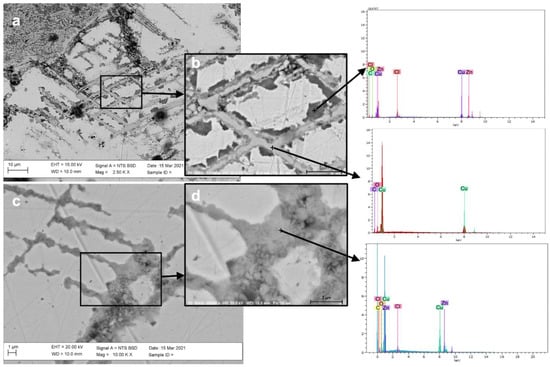
Figure 7.
BSE image in cross section of samples F13 and F14. Fine and parallel strain lines, representing the plastic deformation signs with a high level of corrosion, are highlighted, showing that dezincification followed the stress lines and the grain boundaries of the alloy. The highlighted areas in (a,c) are expanded in (b,d) respectively. EDS spectra refer to points marked with a cross and reveal a Zn depletion inside the lines.
4. Discussion
Previous studies [39] proposed the classification of two types of patina for metal artifacts, according to their formation mechanisms and characteristics: Type I and Type II patinas. The Type I structure, or “even” patina, presents an unaltered aesthetic and a corroded layer, usually mineralized and compact, with excellent corrosion resistance properties. It is generally called “noble patina”. The Type II structure is called “coarse” patina. This kind of patina has been damaged in depth, with the presence of different copper corrosion deposits on the surface and chlorides at the layer–core interface.
SEM-EDS analyses revealed a coarse-type structure [39] for the patina of the samples A3 and F1. The corroded surface layer was due to the dezincification process and usually occurs in artefacts having low amounts of Sn in the alloy [48,49]. The presence of an adequate amount of tin in the alloy (≤1%) promotes the formation of a passive film at the unaltered metal-corrosion product interface [50]. In that area of the samples the oxidation state of Sn is >2 and limits the process of anodic dissolution, increasing the resistance of the Cu-Zn-based alloy to corrosion [51]. In particular, the studied coins had an amount of Sn lower than 1% (Table 1). Moreover, as previously reported [26], quantitative analyses on orichalcum coins minted during the Roman Empire show a maximum Sn value of 2.27% and a minimum value of 0.01%. The altered patina of the samples here studied was similar in thickness to that identified by Robbiola et al. [39] as Type II structure patina (“coarse patina”), i.e., from ~200 µm to several mm.

Table 1.
Maximum (Max.), minimum (Min.) and average (Avg.) EMP analyses of major elements only in non-corroded areas of the samples. For a comparison with other samples minted from the 1st century BCE and the 1st century CE see [26]. b.l.d.= below detection limit.
The strain lines as evidence of plastic deformation shown by SEM and FESEM imaging indicated heavy cold-working during the minting process, where the metal planchet was hammered between two dies below its recrystallization temperature. This hammering, required for coinage, caused the slip of crystal planes and, as a consequence, a series of parallel movements, which resulted in fine lines [7,46]. Such slip usually occurs along the line of the maximum shearing stress [52]. However, the twin strain lines observed do not present additional deformation, as shown in SEM images (Figure 3, Figure 6a,b, and Figure 7). This seems to suggest that further hammering was not performed on the coins after minting (e.g., coinage defect as random multiple strikes by mistake or intentional overstriking, using an old coin as a planchet). The heterogeneity in composition was highlighted by studying the stress lines using a scanning electron microscope. This meant that the slip lines had been preferentially affected by dezincification with respect to the non-stressed zones of alloy, as highlighted by HR-FESEM images of the quadrantes (Figure 7). Micrographic investigations on other ancient alloys proved that the dendritic arms in cast objects were preferentially corroded, compared to the inter-dendritic areas, which were preferentially preserved [46]. Therefore, it could be suggested that the strain lines here observed represented preferential areas of corrosion in orichalcum samples, like the dendritic structures for other copper-based alloys [7].
The trans-granular and inter-granular corrosion, and the resulting dezincification, were clearly observed in X-ray maps of the elemental distribution of sample F1 (Figure 5), which could be attributed to the Cu-Zn ratio; as observed by Sieradzki et al. [53]. The corrosion process could be induced in trans-granular zones of alloys with Zn content between 20% and 30% and it was less likely in samples where the percentage was lower (up to 10%). In the case of Roman orichalcum coins, the average content of Zn in the alloy was ~22% and the average content of Cu was ~78%, but in our particular case samples A3 and F1 had an average content of Zn slightly higher than samples F13 and F14 and this could also justify differences in degradation processes. These values were referred to quantitative analyses on non-altered areas of the orichalcum samples (core of the coins), as reported in Table 1. The quantitative results (Table 1) showed a lower amount of Zn compared to the composition of Roman orichalcum coins previously studied [26]. According to Sieradzki et al. [53], the trans-granular stress corrosion could be correlated with the dislocated structures of deformed alloys when in contact with basic solutions. Other authors [7,54] report that the local strain due to cold working seems to have a key role in the acceleration of stress corrosion cracking, deforming grain boundaries and inducing corrosion.
The occurrence of chlorine (Figure 5 and Figure 7) as an exogenous element from the burial environment provided an ideal medium for galvanic reactions between Cu and Zn, involving the corroded area and penetrating to the inner zones of the coins. It is known that chlorine is the main corroding agent for Cu-based archaeological artefacts. It can form copper chlorides and oxychlorides at the interface between the metal surface and the environment. In particular, chlorides can be formed in a marine atmosphere (on surfaces exposed to the wind from the sea, or in marine soil containing Cl-rich fluids) [55,56,57]. The presence of chloride ions in solution accelerates the dezincification reaction [58]. Furthermore, it has been experimentally shown that as the corrosion reaction increases [15], copper chlorides can form and fill the porous structures. The first ionization of Zn determines superficial dezincification and, thus, indirect Cu-enrichment on the surface layer. Moreover, Cu can also be lost, causing decuprification and, thus, providing porosity systems [48,59], clearly visible in Figure 2. In addition, the increasing of Cl at the corroded–uncorroded interface (Figure 5) was already found in previous studies on archaeological artefacts and artificial reference materials for historical metals [39,48]. According to these studies, chlorine increase is typical of intense interactions between samples and environmental agents and confirms that the patinas of A3 and F1 samples belonged to the so-called Type II [39].
The dupondius A3 and the sestertius F1 were similar in composition (Table 1) to the experimental “brass-IV” sample used by Liang and co-authors [15] to simulate the corrosion of Cu-Zn-based archaeological artefacts in a laboratory. In that case, the artificially corroded surface of sample “brass-IV” appeared free of porosity on the external surface of the patina, which was uniform, compared to samples with less amounts of copper in the alloy. In the thickness of the corrosion layer no cracks and pores were found. Furthermore, the laboratory sample brass-IV, subjected to impedance spectroscopy, exhibited excellent corrosion. In our case, despite the ~81% wt. of Cu, both samples fell into Type II structure patinas. This suggested that a long period of burial history, along with different soil composition and constraints of the system, could significantly change the state of conservation of the coins [17].
The occurrence of Si as an exogenous element in the patinas of samples F13 and F14 protected the two quadrantes from corrosion due to good resistivity value of Si. In fact, it is known that silica is chemically inert, thanks to the binding energy (360 kJ·mol−1) of the tetrahedral structure. Silicon from the soil, in contact with the outer layer of the coins, produced a protective and compact patina, which slowed down further degradation processes of the metal, such as the infiltration of Cl-rich fluids. Based on the low occurrence of Zn and soil elements, these patinas could be described as Type I structure patinas (“even” patinas), according to Robbiola et al. [39]. Indeed, SEM imaging revealed a good degree of conservation of the metal core of these two samples (Figure 6), considering the external layer to be passive and protective, the so-called “noble patinas”. The presence of voids could be attributable to the dissolved gases in the melted alloy during the casting of the planchet. The elongated shape of the pores was due to the force exerted by the hammering of the planchet, to mint the coin [46]. Despite the low presence of Cl in the stressed slip lines, as preferential areas of corrosion, the natural coating effect of the Si-rich patina was confirmed by the absence of Cl at the patina–core interface and by the good degree of preservation of the metal inner cores.
The use of HR-SEM sub-microscale imaging showed the occurrence of corroded areas, in which a morphological evolution from a homogeneous metallic area to corroded micro globular-shaped structures was observed, along with the formation of secondary Cu-mineral phases (Figure 7c,d). This confirmed that, despite the presence of Type I patina, which protects the sample from corrosion [39], an early stage of corrosive processes occurred.
HR imaging (Figure 3 and Figure 7) confirmed that the corrosion is the result of the contribution of complex mechanisms [46,53,54], i.e. metal working deformation, chemical composition of the alloy linked to the Cu-Zn ratio and the environmental history of the coins. In addition, the investigation on coins subjected to real and long conditions of environmental stress allowed taking into account various degradation factors, such as the interaction between soil elements (e.g. Si) and copper corrosion products.
Figure 8 summarises the complex corrosion pattern, occurring in coins that have undergone long and natural degradation processes. Both the Type I and Type II structures can be described as a series of overlapped layers that differ in chemical composition and degradation pattern (presence of porosity and/or cracks, degree of homogeneity of the external layer, degree of corrosion of the innermost layers). From a visual point of view, bronze and orichalcum coins can be easily confused when their surfaces are degraded. In cases of a good state of conservation, numismatic investigation can help to distinguish each coin by denomination, issuer and year of minting and, consequently, allows hypothesizing of the composition of the samples, according to historical sources. When the state of conservation is poor, due to severe corrosion of the surfaces, the legends and the types are illegible, both on the obverse and on the reverse. This prevents identification of the samples. In this case, an archaeometrical investigation, with a multi-analytical approach, is the best way to solve numismatic and archaeological queries.
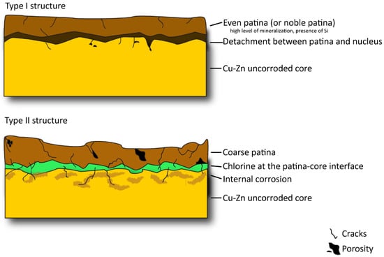
Figure 8.
Schematic representation of the Type I (up) and Type II (down) corrosive structures of orichalcum samples. In the scheme the damages that occurred in both types of structures are evident, highlighting the highest degree of degradation in Type II, due to cracks and induced porosity causing internal corrosion and the settlement of chlorine-rich fluid at the patina–core interface.
Considering the most recent literature [31,60], metal artefacts, once extracted from their burial environment, continue their corrosion processes, due to change of environment itself. In particular, the main causes of artefact corrosion in museums are temperature, relative humidity, atmospheric pollutants and dust. For these reasons, archaeological metal objects should be exhibited and/or stored in a specially designed indoor environment and, depending on the specific case, protected with specific and tested coatings.
5. Conclusions
The micro and sub-micro structures of Roman orichalcum coins were investigated applying SEM and HR-FESEM, at different resolutions, and X-ray elements mapping. The following information about the corrosive process and productive technology were obtained:
- The investigation of the patinas revealed the occurrence of selective trans-granular corrosion, due to the Cu-Zn ratio and to the presence of exogenous elements, such as chlorine;
- Two different degrees of corrosion were observed, i.e. F13 and F14 samples were protected by the presence of exogenous Si in the patinas, while the silicon-free coins, A3 and F1, showed a severe condition of degradation;
- X-ray maps of the main elements and high magnification investigation showed there was also the presence of corrosion inside the slipped crystal planes, due to plastic deformation induced by hammering. The related strain lines were heterogeneous in composition and Zn depleted;
- Sub-micro scale images indicated an early stage of corrosive processes, despite the presence of the noble patina (Type I) that usually protects the sample from corrosion (Figure 6). This consideration suggested that the structures produced by mechanical stress could be the trigger of corrosion and degradation processes in orichalcum.
- The use of SEM-EDS and HR-FESEM-EDS confirmed the use of cold-working by hammering to mint coins.
- Laboratory simulation could be a useful guide to understand the dezincification process, but cannot completely describe the long-term corrosive mechanism influenced by several random factors, such as mechanical stress or environmental events.
Author Contributions
M.D.F. and C.D.V. designed the study, planned the experiments, interpreted SEM-EDS and HR-FESEM-EDS data and wrote the manuscript. A.C.F. wrote the manuscript together with other authors. F.C. obtained the coins here studied from different collections of Private Collectors and wrote the historical context. L.M. read the manuscript. All authors have read and agreed to the published version of the manuscript.
Funding
This research was funded by Sapienza “Ateneo Funding 2021”.
Acknowledgments
Financial support was provided by Sapienza University of Rome (Ateneo funding, 2021). “PhD-grants” of the Department of Earth Sciences, Sapienza University of Rome, are gratefully. The authors are indebted to Private Collectors for generously providing the coins used for the study. The SNN-lab of the Center for Nanotechnology for Engineering (CNIS), Sapienza University of Rome, is gratefully acknowledged.
Conflicts of Interest
The authors declare that they have no known competing financial interests or personal relationships that could have appeared to influence the work reported in this paper.
References
- Xavier, J.R.; Nallaiyan, R. Corrosion Inhibitive Properties and Electrochemical Adsorption Behaviour of Some Piperidine Derivatives on Brass in Natural Sea Water. J. Solid State Electrochem. 2012, 16, 391–402. [Google Scholar] [CrossRef]
- Shi, P.; Wang, Q.; Xu, Y.; Luo, W. Corrosion Behavior of Bulk Nanocrystalline Copper in Ammonia Solution. Mater. Lett. 2011, 65, 857–859. [Google Scholar] [CrossRef]
- Inberg, A.; Ashkenazi, D.; Cohen, M.; Iddan, N.; Cvikel, D. Corrosion Products and Microstructure of Copper Alloy Coins from the Byzantine-Period Ma’agan Mikhael B Shipwreck, Israel. Microchem. J. 2018, 143, 400–409. [Google Scholar] [CrossRef]
- Jiang, J.; Xu, D.; Xi, T.; Shahzad, M.B.; Khan, M.S.; Zhao, J.; Fan, X.; Yang, C.; Gu, T.; Yang, K. Effects of Aging Time on Intergranular and Pitting Corrosion Behavior of Cu-Bearing 304L Stainless Steel in Comparison with 304L Stainless Steel. Corros. Sci. 2016, 113, 46–56. [Google Scholar] [CrossRef]
- Di Turo, F. Limits and Perspectives of Archaeometric Analysis of Archaeological Metals: A Focus on the Electrochemistry for Studying Ancient Bronze Coins. J. Cult. Herit. 2019, 43, 271–281. [Google Scholar] [CrossRef]
- Hou, Y.; Chen, L.; Li, Z.; Zhao, G.; Zhang, C. Effects of Artificial Aging on Microstructure, Mechanical Properties and Stress Corrosion Cracking of a Novel High Strength 7A99 Al Alloy. Mater. Sci. Eng. A 2020, 780, 139217. [Google Scholar] [CrossRef]
- Ashkenazi, D. How Can Fracture Mechanics and Failure Analysis Assist in Solving Mysteries of Ancient Metal Artifacts? Archaeol. Anthropol. Sci. 2020, 12, 34. [Google Scholar] [CrossRef]
- Ashkenazi, D.; Inberg, A.; Langgut, D.; Hendler, N.; Cvikel, D. Brass–Iron Couple and Brass–Iron–Wood Ternary System of Metal Objects from the Akko 1 Shipwreck (Israel). Corros. Sci. 2016, 110, 228–241. [Google Scholar] [CrossRef]
- Doménech-Carbó, M.T.; Di Turo, F.; Montoya, N.; Catalli, F.; Doménech-Carbó, A.; De Vito, C. FIB-FESEM and EMPA Results on Antoninianus Silver Coins for Manufacturing and Corrosion Processes. Sci. Rep. 2018, 8, 10676. [Google Scholar] [CrossRef] [Green Version]
- Oudbashi, O.; Wanhill, R. Long-Term Embrittlement of Ancient Copper and Silver Alloys. Heritage 2021, 4, 130. [Google Scholar] [CrossRef]
- Ashkenazi, D.; Nusbaum, I.; Shacham-Diamand, Y.; Cvikel, D.; Kahanov, Y.; Inberg, A. A Method of Conserving Ancient Iron Artefacts Retrieved from Shipwrecks Using a Combination of Silane Self-Assembled Monolayers and Wax Coating. Corros. Sci. 2017, 123, 88–102. [Google Scholar] [CrossRef]
- Chiavari, C.; Bernardi, E.; Balbo, A.; Monticelli, C.; Raffo, S.; Bignozzi, M.C.; Martini, C. Atmospheric Corrosion of Fire-Gilded Bronze: Corrosion and Corrosion Protection during Accelerated Ageing Tests. Corros. Sci. 2015, 100, 435–447. [Google Scholar] [CrossRef]
- Letardi, P. Laboratory and Field Tests on Patinas and Protective Coating Systems for Outdoor Bronze Monuments. In Proceedings of the International Conference on Metals Conservation, Canberra, Australia, 4–8 October 2004; pp. 379–387. [Google Scholar]
- Liao, B.; Cen, H.; Chen, Z.; Guo, X. Corrosion Behavior of Sn-3.0Ag-0.5Cu Alloy under Chlorine-Containing Thin Electrolyte Layers. Corros. Sci. 2018, 143, 347–361. [Google Scholar] [CrossRef]
- Liang, Z.; Jiang, K.; Zhang, T.; Lin, S. Corrosion Behavior of Brass from the Western Zhou Dynasty in an Archeological-Corrosive Medium. J. Alloys Compd. 2021, 865, 158579. [Google Scholar] [CrossRef]
- Barrena, M.I.; Gómez de Salazar, J.M.; Soria, A. Corrosion of Brass Archaeological Blinker: Characterisation of Natural Degradation Process. Mater. Lett. 2008, 62, 3944–3946. [Google Scholar] [CrossRef]
- Papadopoulou, O.; Alessandri, O.C.; Vassiliou, P.; Grassini, S.; Angelini, E.; Gouda, V. Soil-Induced Corrosion of Ancient Roman Brass—A Case Study. Mater. Corros. 2016, 67, 160–169. [Google Scholar] [CrossRef]
- Pronti, L.; Felici, A.C.; Alesiani, M.; Tarquini, O.; Bracciale, M.P.; Santarelli, M.L.; Pardini, G.; Piacentini, M. Characterisation of Corrosion Layers Formed under Burial Environment of Copper-Based Greek and Roman Coins from Pompeii. Appl. Phys. A 2015, 121, 59–68. [Google Scholar] [CrossRef]
- Bernabale, M.; Nigro, L.; Montanari, D.; Niveau-de-Villedary, A.M.; De Vito, C. Microstructure and Chemical Composition of a Sardinian Bronze Axe of the Iron Age from Motya (Sicily, Italy). Mater. Charact. 2019, 158, 109957. [Google Scholar] [CrossRef]
- Salvan, C.; Briottet, L.; Baffie, T.; Guetaz, L.; Flament, C. CuCrZr Alloy Produced by Laser Powder Bed Fusion: Microstructure, Nanoscale Strengthening Mechanisms, Electrical and Mechanical Properties. Mater. Sci. Eng. A 2021, 826, 141915. [Google Scholar] [CrossRef]
- Conte, A.M.; Pulci, O.; Misiti, M.C.; Lojewska, J.; Teodonio, L.; Violante, C.; Missori, M. Visual Degradation in Leonardo Da Vinci’s Iconic Self-Portrait: A Nanoscale Study. Appl. Phys. Lett. 2014, 104, 224101. [Google Scholar] [CrossRef]
- Giorgi, R.; Baglioni, M.; Berti, D.; Baglioni, P. New Methodologies for the Conservation of Cultural Heritage: Micellar Solutions, Microemulsions, and Hydroxide Nanoparticles. Acc. Chem. Res. 2010, 43, 695–704. [Google Scholar] [CrossRef] [PubMed]
- Michelin, A.; Drouet, E.; Foy, E.; Dynes, J.; Neff, D.; Dillmann, P. Investigation at the Nanometre Scale on the Corrosion Mechanisms of Archaeological Ferrous Artefacts by STXM. J. Anal. At. Spectrom. 2013, 28, 59–66. [Google Scholar] [CrossRef]
- Bernabale, M.; Nigro, L.; Montanari, D.; De Vito, C. Exploring the Chemical Composition and Corrosion Patterns of Arrowheads Used in the Siege of Motya (397 BC) through a Multi-Analytical Approach. J. Cult. Herit. 2021, 52, 146–152. [Google Scholar] [CrossRef]
- Di Fazio, M.; Felici, A.C.; Catalli, F.; Doménech-Carbó, M.T.; De Vito, C.; Doménech-Carbó, A. Solid-State Electrochemical Characterization of Emissions and Authorities Producing Roman Brass Coins. Microchem. J. 2020, 152, 104306. [Google Scholar] [CrossRef]
- Di Fazio, M.; Felici, A.C.; Catalli, F.; De Vito, C. Microstructure and Chemical Composition of Roman Orichalcum Coins Emitted after the Monetary Reform of Augustus (23 B.C.). Sci. Rep. 2019, 9, 12668. [Google Scholar] [CrossRef] [PubMed] [Green Version]
- Ager, F.J.; Gómez-Tubío, B.; Paúl, A.; Gómez-Morón, A.; Scrivano, S.; Ortega-Feliu, I.; Respaldiza, M.A. Combining XRF and GRT for the Analysis of Ancient Silver Coins. Microchem. J. 2016, 126, 149–154. [Google Scholar] [CrossRef]
- Di Fazio, M.; Di Turo, F.; Medeghini, L.; Fabrizi, L.; Catalli, F.; De Vito, C. New Insights on Medieval Provisini Silver Coins by a Combination of Non-Destructive and Micro-Invasive Techniques. Microchem. J. 2019, 144, 309–318. [Google Scholar] [CrossRef]
- Fabrizi, L.; Di Turo, F.; Medeghini, L.; Di Fazio, M.; Catalli, F.; De Vito, C. The Application of Non-Destructive Techniques for the Study of Corrosion Patinas of Ten Roman Silver Coins: The Case of the Medieval Grosso Romanino. Microchem. J. 2019, 145, 419–427. [Google Scholar] [CrossRef]
- Doménech-Carbó, M.T.; Álvarez-Romero, C.; Doménech-Carbó, A.; Osete-Cortina, L.; Martínez-Bazán, M.L. Microchemical Surface Analysis of Historic Copper-Based Coins by the Combined Use of FIB-FESEM-EDX, OM, FTIR Spectroscopy and Solid-State Electrochemical Techniques. Microchem. J. 2019, 148, 573–581. [Google Scholar] [CrossRef]
- Artesani, A.; Di Turo, F.; Zucchelli, M.; Traviglia, A. Recent Advances in Protective Coatings for Cultural Heritage—An Overview. Coatings 2020, 10, 217. [Google Scholar] [CrossRef] [Green Version]
- L’héronde, M.; Bouttemy, M.; Mercier-Bion, F.; Neff, D.; Apchain, E.; Etcheberry, A.; Dillmann, P. Multiscale Study of Interactions Between Corrosion Products Layer Formed on Heritage Cu Objects and Organic Protection Treatments. Heritage 2019, 2, 2640–2651. [Google Scholar] [CrossRef] [Green Version]
- Giraud, T.; Gomez, A.; Lemoine, S.; Pelé-Meziani, C.; Raimon, A.; Guilminot, E. Use of Gels for the Cleaning of Archaeological Metals. Case Study of Silver-Plated Copper Alloy Coins. J. Cult. Herit. 2021, 52, 73–83. [Google Scholar] [CrossRef]
- Corsi, J.; Grazzi, F.; Lo Giudice, A.; Re, A.; Scherillo, A.; Angelici, D.; Allegretti, S.; Barello, F. Compositional and Microstructural Characterization of Celtic Silver Coins from Northern Italy Using Neutron Diffraction Analysis. Microchem. J. 2016, 126, 501–508. [Google Scholar] [CrossRef]
- Ingo, G.M.; Riccucci, C.; Faraldi, F.; Pascucci, M.; Messina, E.; Fierro, G.; Di Carlo, G. Roman Sophisticated Surface Modification Methods to Manufacture Silver Counterfeited Coins. Appl. Surf. Sci. 2017, 421, 109–119. [Google Scholar] [CrossRef]
- Di Turo, F.; Montoya, N.; Piquero-Cilla, J.; De Vito, C.; Coletti, F.; Favero, G.; Doménech-Carbó, T.M.; Doménech-Carbó, A. Dating Archaeological Strata in the Magna Mater Temple Using Solid-state Voltammetric Analysis of Leaded Bronze Coins. Electroanalysis 2018, 30, 361–370. [Google Scholar] [CrossRef] [Green Version]
- Di Turo, F.; Coletti, F.; De Vito, C. Investigations on Alloy-Burial Environment Interaction of Archaeological Bronze Coins. Microchem. J. 2020, 157, 104882. [Google Scholar] [CrossRef]
- Dumitriu, I.; Fierascu, R.; Catangiu, A.; Neata, M.; Ion, R.; Somoghi, R. A Synthetic Approach into the Restoration and Conservation of Metal Artifacts (Coins). J. Optoelectron. Adv. Mater. 2011, 13, 874. [Google Scholar]
- Robbiola, L.; Blengino, J.-M.; Fiaud, C. Morphology and Mechanisms of Formation of Natural Patinas on Archaeological Cu–Sn Alloys. Corros. Sci. 1998, 40, 2083–2111. [Google Scholar] [CrossRef]
- Caley, E.R. Orichalcum and Related Ancient Alloys; Numismatic notes and Monograph; American Numismatic Society: New York, NY, USA, 1964. [Google Scholar]
- Craddock, P.T. The Composition of the Copper Alloys Used by the Greek, Etruscan and Roman Civilizations. J. Archaeol. Sci. 1978, 5, 1–16. [Google Scholar] [CrossRef]
- Sutherland, C.H.V. The Roman Imperial Coinage: From 31 BC to AD 69: With Introd. to the Mints; Spink: London, UK, 1984; ISBN 978-0-907605-09-6. [Google Scholar]
- Catalli, F. Numismatica Greca e Romana; Istituto poligrafico e Zecca dello Stato: Roma, Italy, 2003. [Google Scholar]
- Barello, F. Archeologia Della Moneta: Produzione e Utilizzo Nell’antichità; Carocci: Roma, Italy, 2006; ISBN 978-88-430-3712-4. [Google Scholar]
- Pouchou, J.; Pichior, F. “PAP” f(RZ) Procedure for Improved Quantitative Analysis. In Microbeam Analysis; Armstrong, J.T., Ed.; San Francisco Press: San Francisco, CA, USA, 1985; pp. 104–106. [Google Scholar]
- Scott, D.A. Metallography and Microstructure of Ancient and Historic Metals; Getty Conservation Institute in association with Archetype Books: Marina del Rey, CA, USA, 1991; ISBN 0-89236-195-6. [Google Scholar]
- Doménech-Carbó, A.; Doménech-Carbó, M.T.; Martínez-Lázaro, I. Electrochemical Identification of Bronze Corrosion Products in Archaeological Artefacts. A Case Study. Microchim. Acta 2008, 162, 351–359. [Google Scholar] [CrossRef]
- Constantinides, I.; Adriaens, A.; Adams, F. Surface Characterization of Artificial Corrosion Layers on Copper Alloy Reference Materials. Appl. Surf. Sci. 2002, 189, 90–101. [Google Scholar] [CrossRef]
- Campanella, L.; Alessandri, O.C.; Ferretti, M.; Plattner, S.H. The Effect of Tin on Dezincification of Archaeological Copper Alloys. Corros. Sci. 2009, 51, 2183–2191. [Google Scholar] [CrossRef]
- Karpagavalli, R.; Balasubramaniam, R. Development of Novel Brasses to Resist Dezincification. Corros. Sci. 2007, 49, 963–979. [Google Scholar] [CrossRef]
- Beccaria, A.M.; Poggi, G.; Capannelli, G. The Effect on the Behaviour of Alpha-Brasses in Sea Water of the Addition of Al and Sn—Part 1. Corros. Prev. Control 1989, 36, 169–173. [Google Scholar]
- Moore, H.F.; Ver, T. A Study of Slip Lines, Strain Lines, and Cracks in Metals under Repeated Stress. Univ. Ill. Bull. 1930, XXXVII. [Google Scholar]
- Sieradzki, K.; Kim, J.S.; Cole, A.T.; Newman, R.C. The Relationship Between Dealloying and Transgranular Stress-Corrosion Cracking of Cu-Zn and Cu-Al Alloys. J. Electrochem. Soc. 1987, 134, 1635–1639. [Google Scholar] [CrossRef]
- Ulaganathan, J.; Newman, R.C. The Role of Local Strains from Prior Cold Work on Stress Corrosion Cracking of α-Brass in Mattsson’s Solution. Mater. Charact. 2014, 92, 127–137. [Google Scholar] [CrossRef]
- Mattsson, E. Corrosion of Copper and Brass: Practical Experience in Relation to Basic Data. Br. Corros. J. 1980, 15, 6–13. [Google Scholar] [CrossRef]
- Graedel, T.E. Copper Patinas Formed in the Atmosphere—II. A Qualitative Assessment of Mechanisms. Copp. Patina Form. 1987, 27, 721–740. [Google Scholar] [CrossRef]
- Casaletto, M.P.; De Caro, T.; Ingo, G.M.; Riccucci, C. Production of Reference “Ancient” Cu-Based Alloys and Their Accelerated Degradation Methods. Appl. Phys. A 2006, 83, 617–622. [Google Scholar] [CrossRef]
- Dinnappa, R.K.; Mayanna, S.M. The Dezincification of Brass and Its Inhibition in Acidic Chloride and Sulphate Solutions. Corros. Sci. 1987, 27, 349–361. [Google Scholar] [CrossRef] [Green Version]
- Marshakov, I.K. Corrosion Resistance and Dezincing of Brasses. Prot. Met. 2005, 41, 205–210. [Google Scholar] [CrossRef]
- Abdel-Karim, A.M.; El-Shamy, A.M. A Review on Green Corrosion Inhibitors for Protection of Archeological Metal Artifacts. J. Bio-Tribo-Corros. 2022, 8, 35. [Google Scholar] [CrossRef]
Publisher’s Note: MDPI stays neutral with regard to jurisdictional claims in published maps and institutional affiliations. |
© 2022 by the authors. Licensee MDPI, Basel, Switzerland. This article is an open access article distributed under the terms and conditions of the Creative Commons Attribution (CC BY) license (https://creativecommons.org/licenses/by/4.0/).