
Core Orientation Technology Based on Drilling Trajectory Projection and Its Application in In Situ Stress Measurement of the Deepest Shaft in China


Abstract
:1. Introduction
2. Drilling Trajectory Projection and Core Orientation Technology
2.1. Theoretical Basis
- (1)
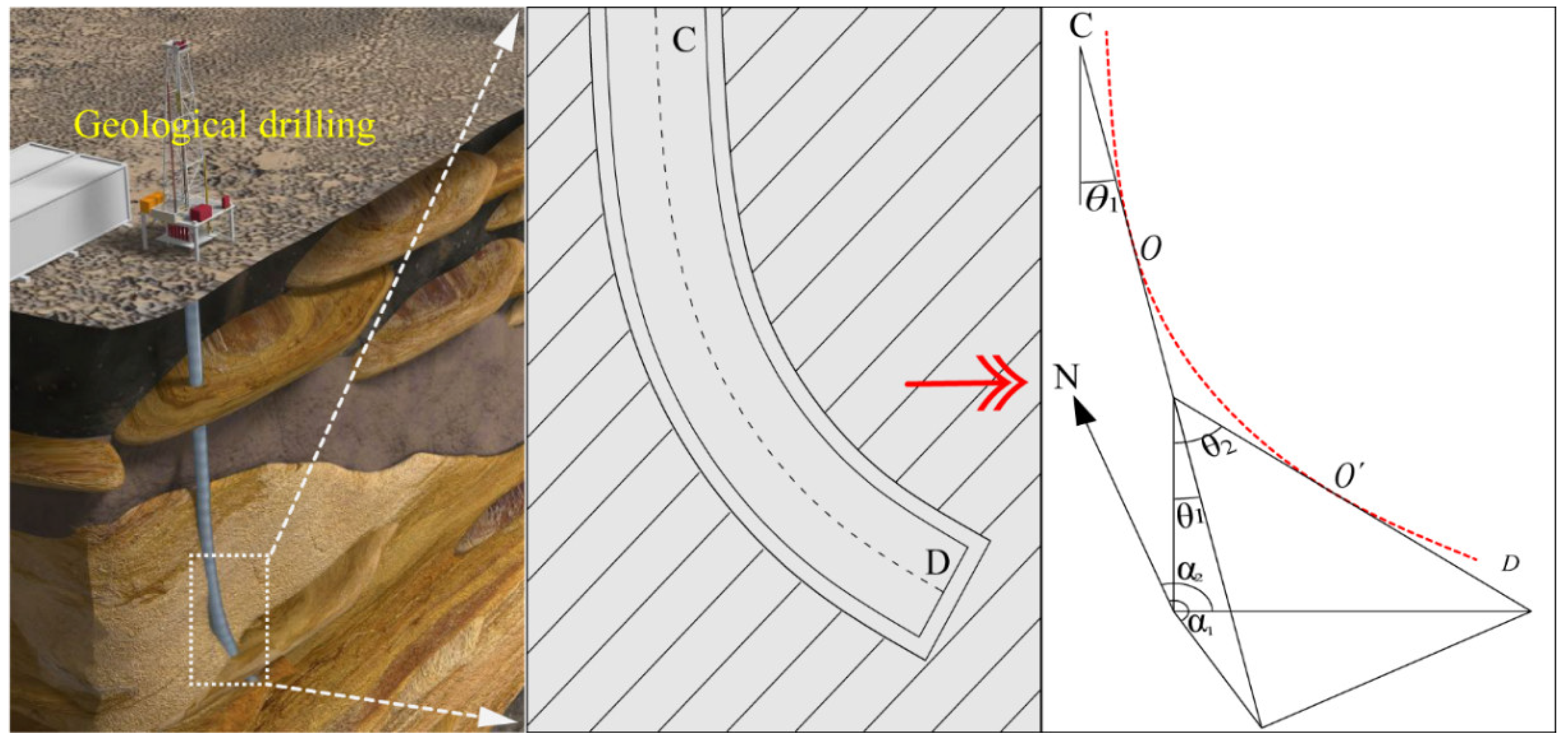
- Absolute bending principle of drilling trajectory
- (2)
- Consistent bending principle of drilling trajectory and core axis
- (3)
- Uniqueness principle of matching the spatial attitude of the borehole and the core
2.2. Establishment of Drill-Core Spatial Attitude Model
3. Implementation of Drilling Trajectory Projection and Core Orientation Technology
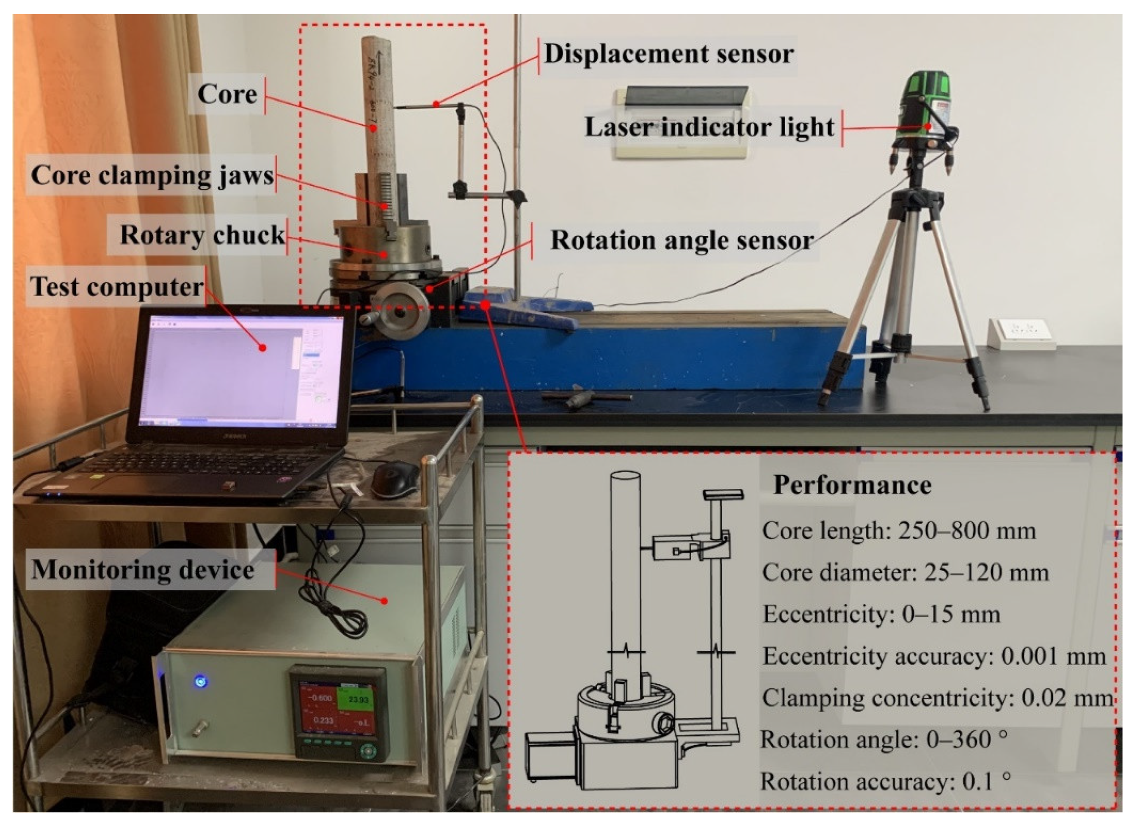
3.1. Development of the Core Orientation System
3.2. Method and Process of Core Orientation
- (1)
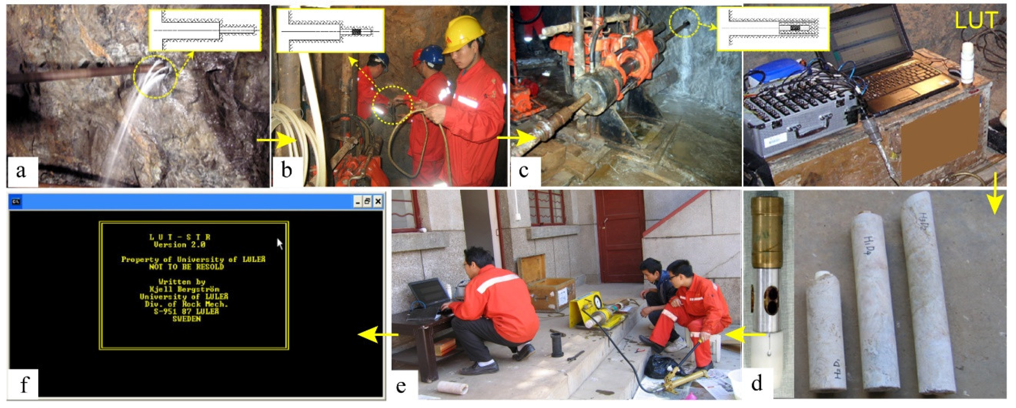
- We connected the test system, screwed the claw on the rotary chuck, and clamped the core so that the axis of the upper-end face of the core coincided with the axis of the chuck. Then, the displacement sensor was closed to the core surface, the displacement and rotation angle monitoring software was opened, and the rotary chuck handle was shaken to drive the core to rotate from the initial position. The displacement measuring device synchronously measured the displacement data of each point on the core surface relative to the chuck axis during the rotation of the core.
- (2)
- The software was employed to solve the displacement peak point and valley point, and the corresponding rotation angle of the peak point and valley point on the rotary chuck (the angle scale was engraved on the rotary chuck) was recorded. When the displacement reached the peak point and valley point, the contact point between the spherical probe of the displacement sensor and the core surface was marked.
- (3)
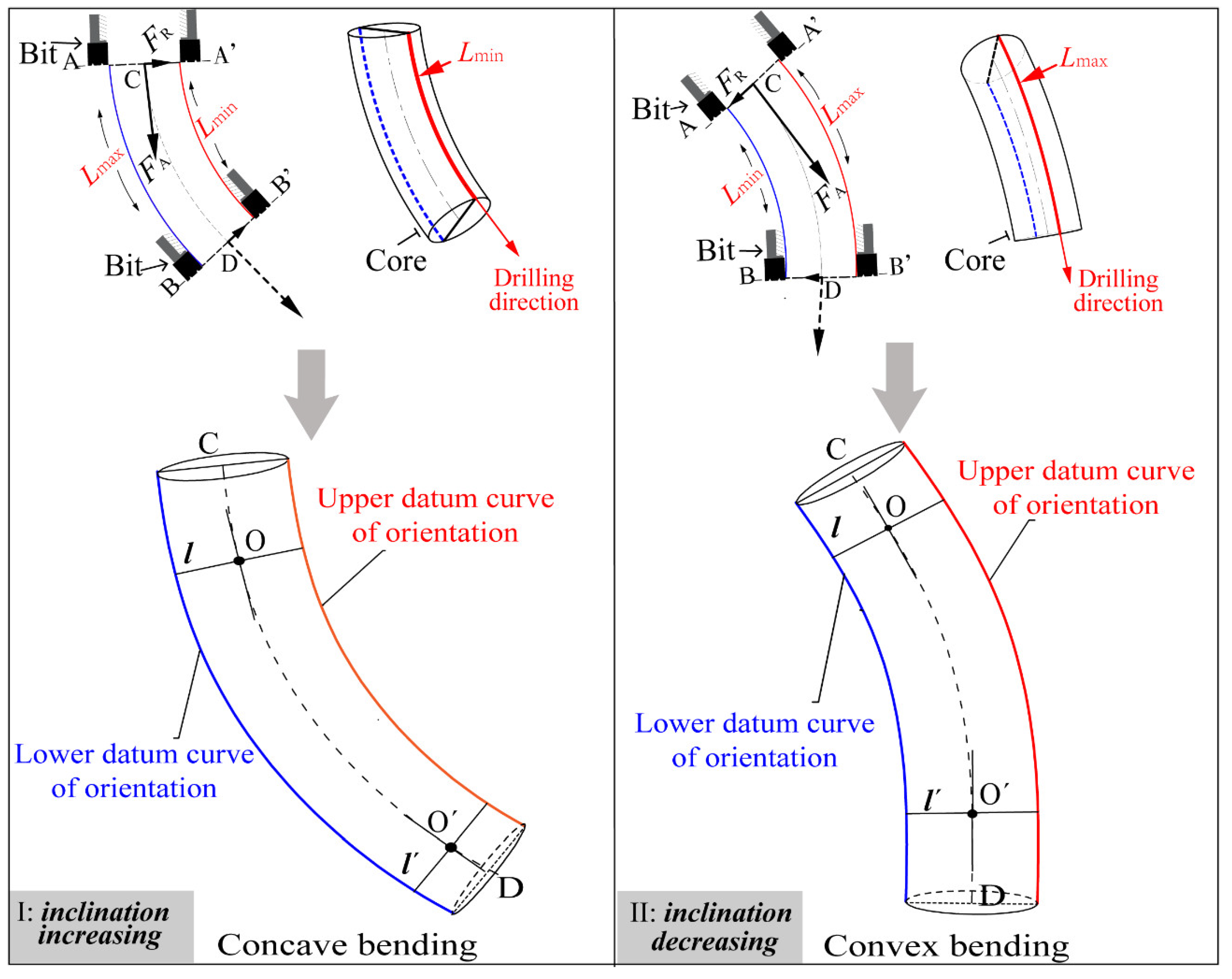
- Multiple displacement peak points and displacement valley points can be obtained by changing the position of the displacement sensor relative to the core and making multiple measurements. Connecting these points can obtain two marking lines: one is the upper datum curve of the orientation, and the other is the lower datum curve of the orientation.
- (4)
- The laser indicator can shoot a vertical beam of light; we aimed it at the core and illuminated the corresponding datum curve. Then, we rotated the upper datum curve to the counterclockwise direction by an azimuth angle. Thus, the light shining on the core by the laser indicator is the north (N) line. This line was marked, and the core was oriented.
4. In Situ Stress Measurement by Reoriented Cores AE Method
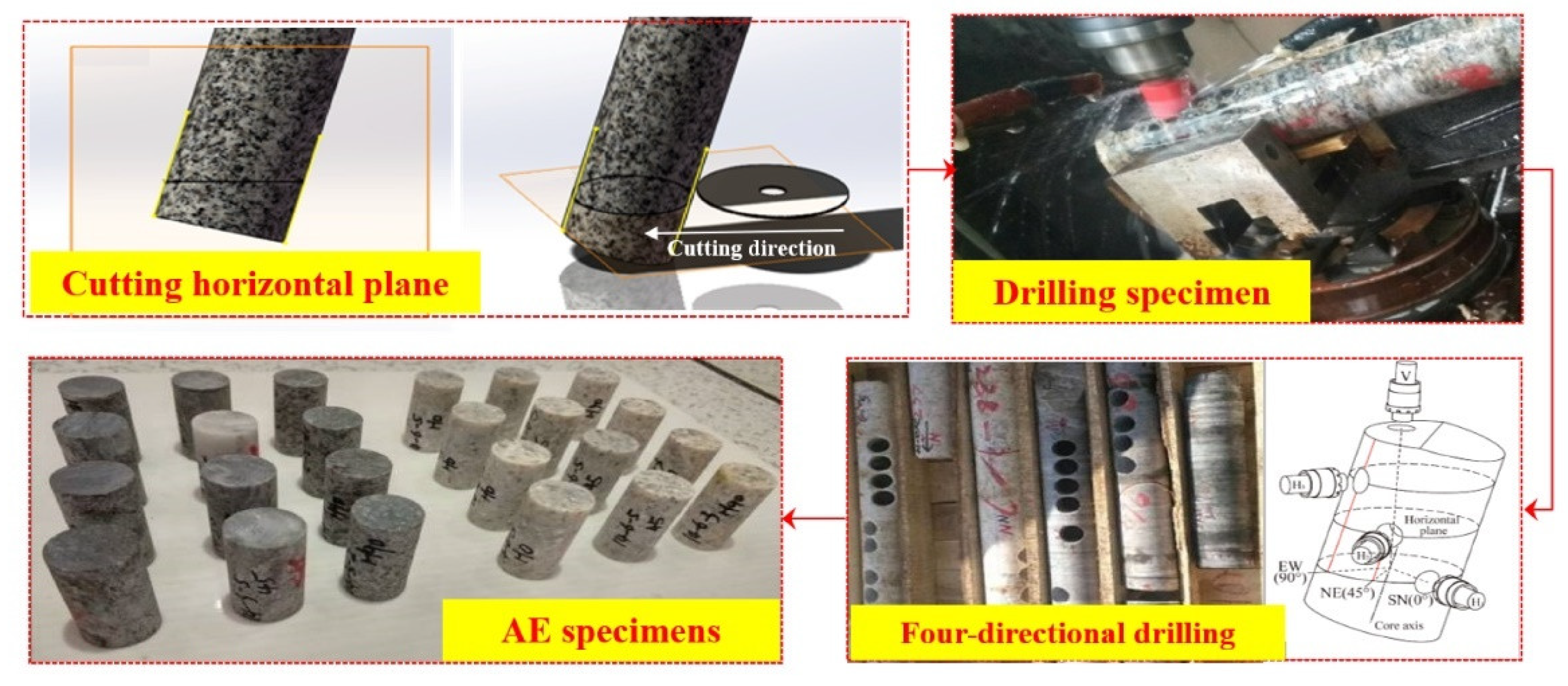
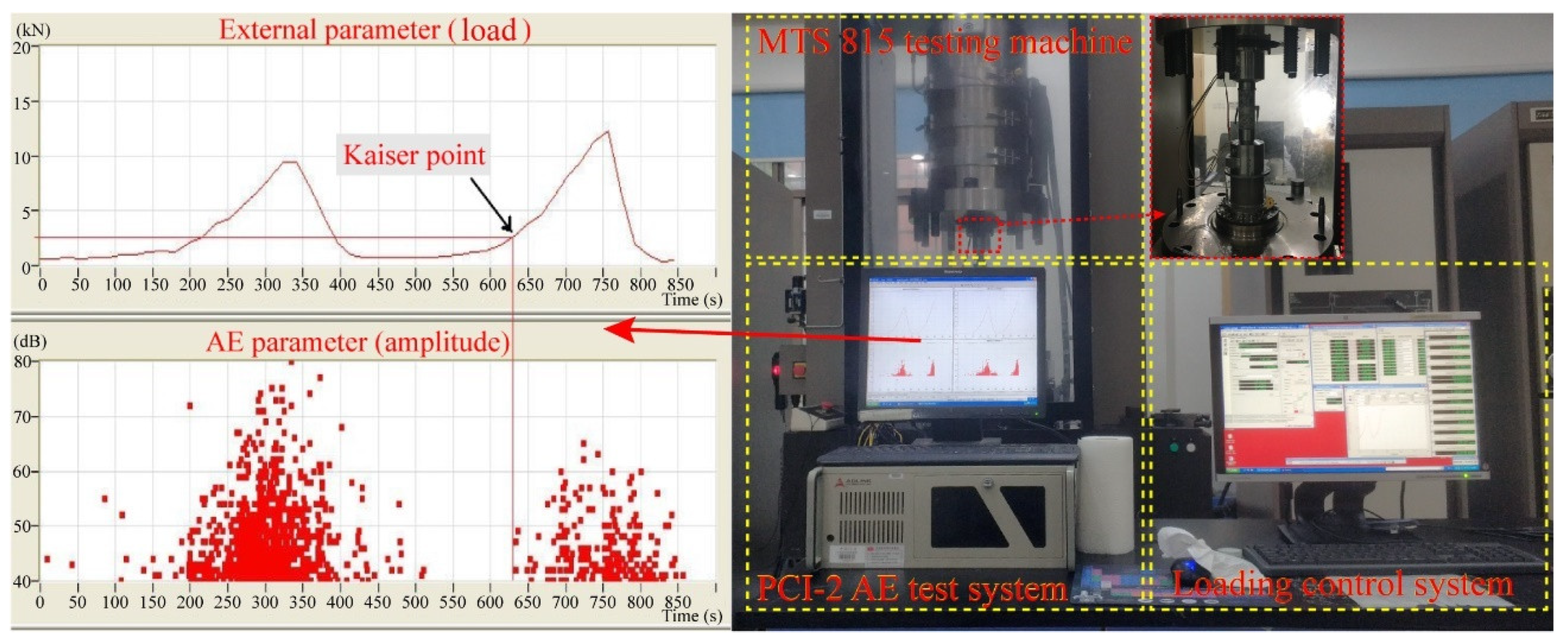
4.1. Sample Preparation and Experimental Equipment
4.2. Test Scheme
4.3. Test Results
4.4. Distribution of In Situ Stress
- (1)
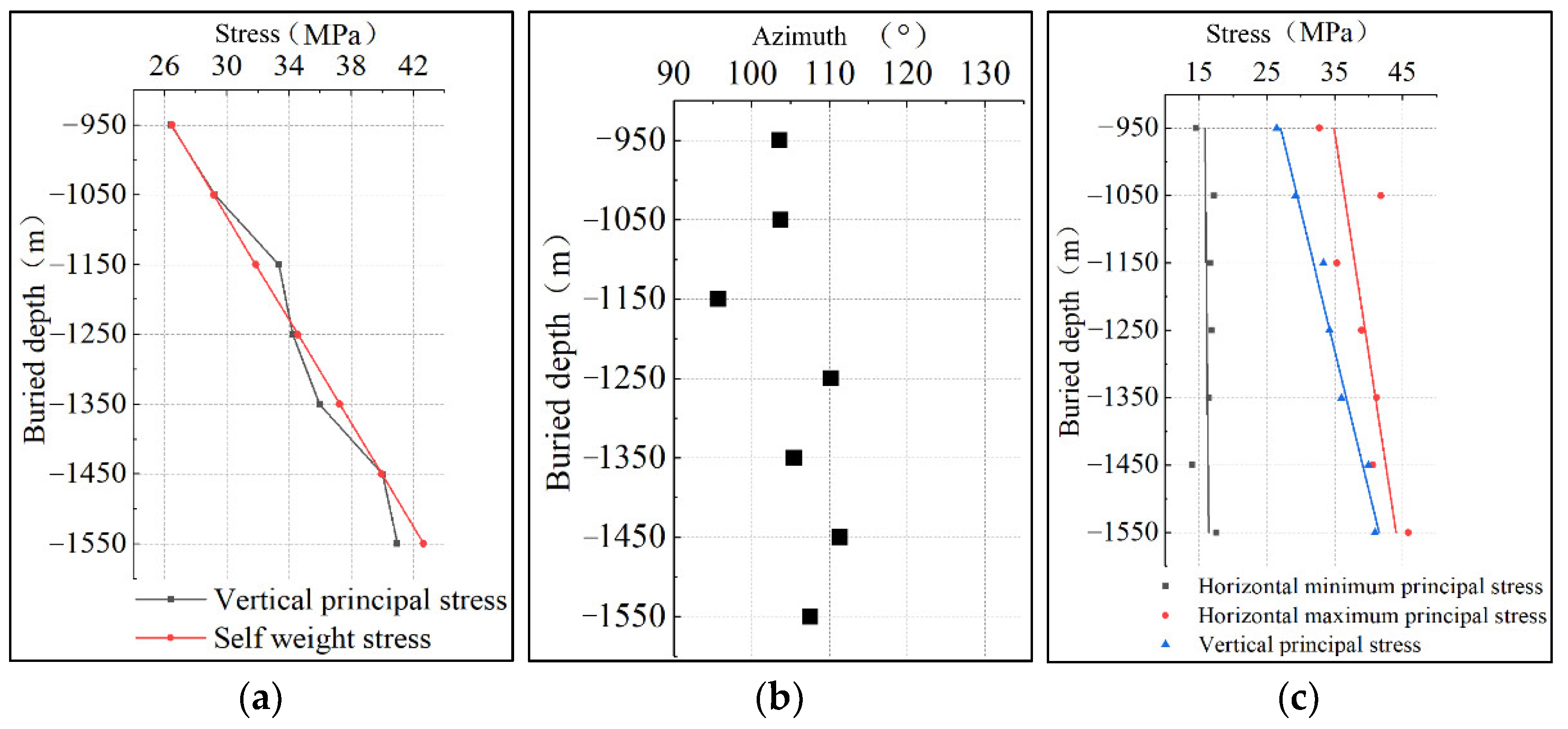
- The vertical principal stress increases nearly linearly with the increase in borehole depth, which is consistent with the self-weight stress at that burial depth (Figure 8a).
- (2)
- The directions of the maximum horizontal principal stress at different depths are similar, ranging from 275.72° to 291.33° (Figure 8b).
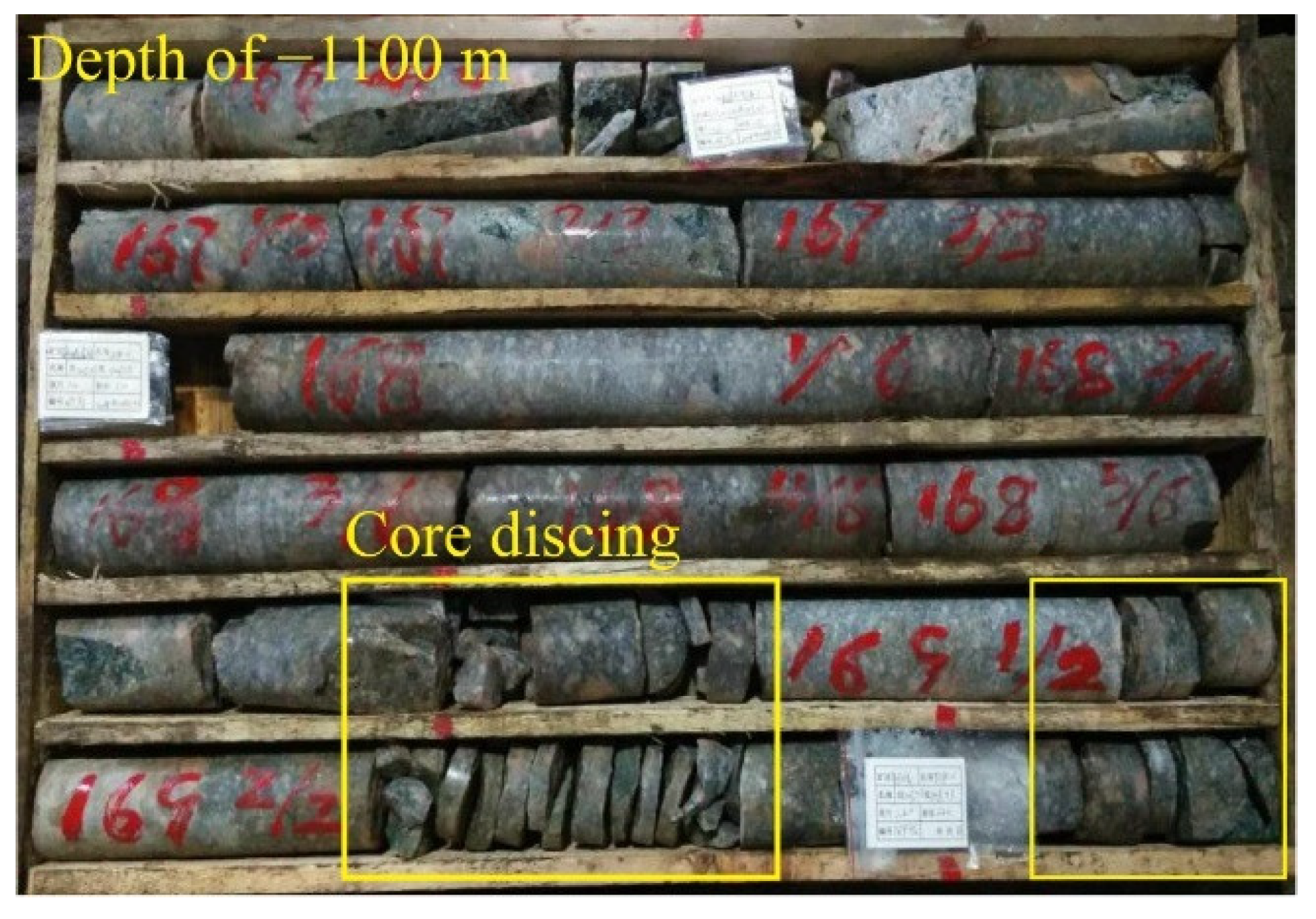
- (3)
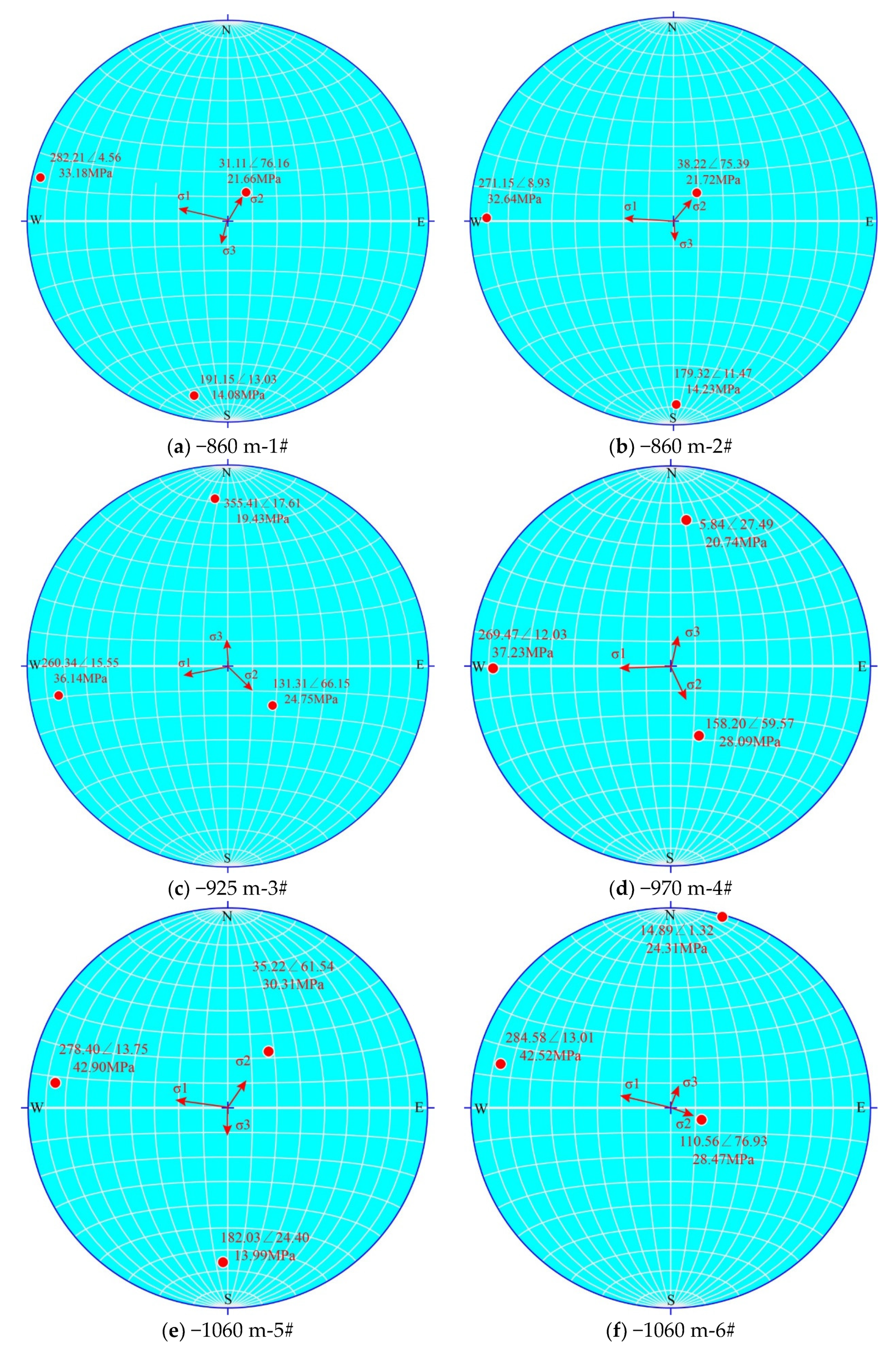
- The in situ stress in the area in which the borehole is located is mainly horizontal tectonic stress. In different soundings of the borehole, the maximum stress is the maximum horizontal principal stress, and the intermediate principal stress is the vertical stress. With the further increase in drilling depth, the dominant role of the horizontal tectonic stress field decreases, and the self-weight stress field increases (Figure 8c). The maximum horizontal principal stress generally shows an increasing trend with the increase in borehole depth. It is worth noting that, at the depth of −1050 m, the maximum horizontal principal stress shows a sudden increase, reaching 41.83 MPa. Under this high stress level, the core discing phenomenon occurs in the borehole, as shown in Figure 9. This finding indicates that the maximum horizontal principal stress undergoes unstable changes in this area and may have geological structural reasons underpinning this.
5. Comparison and Verification
6. Conclusions
- (1)
- The core in an ultradeep geological borehole was reoriented using the developed nonoriented geological core reorientation technology and test system. This technical method only requires the geological core as the test sample without redundant operation in the process of drilling. The utility model has the advantages of low cost, simple operation, and strong applicability.
- (2)
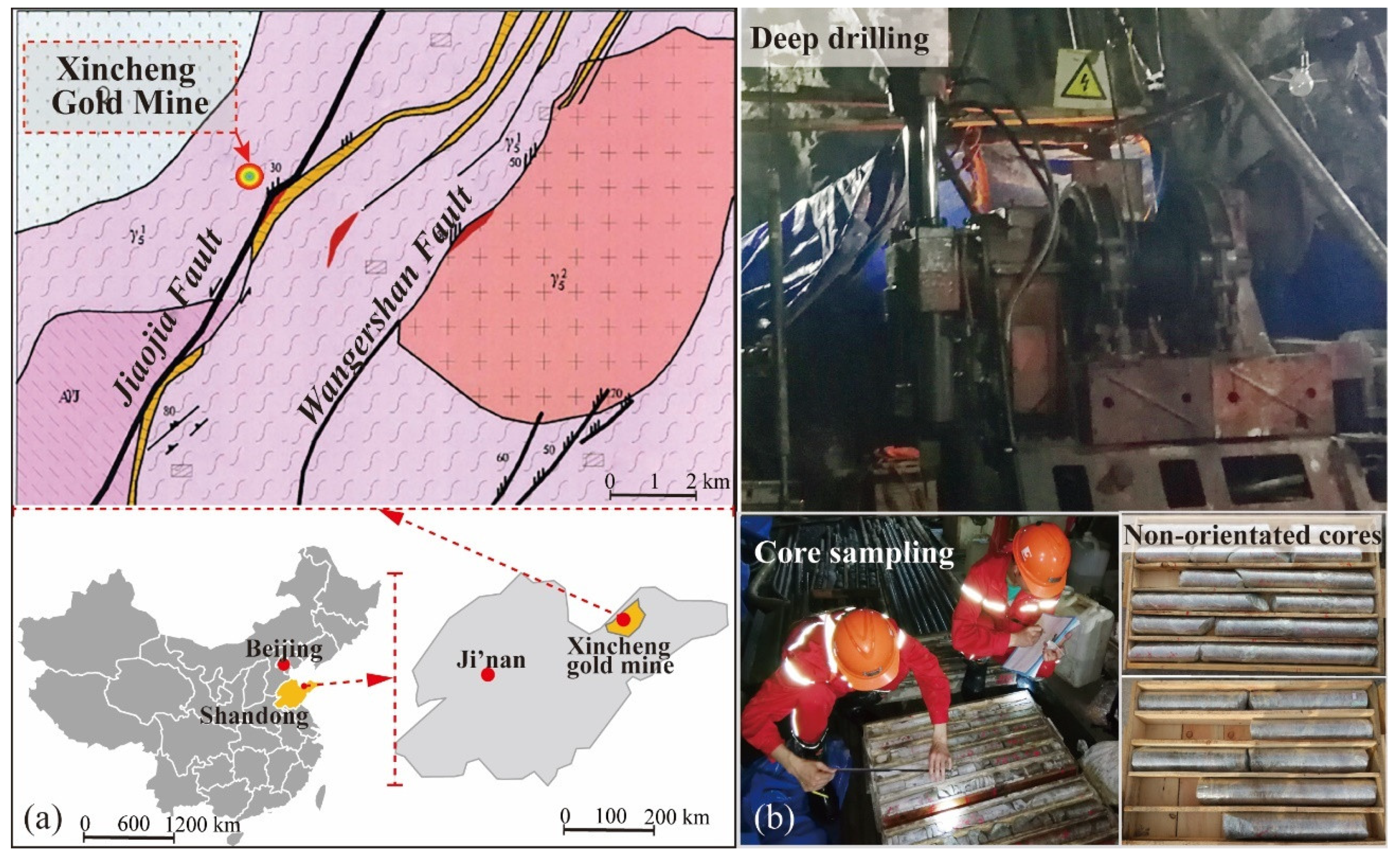
- To obtain the in situ stress distribution of the deepest shaft of Xincheng Gold Mine, the cores collected from a −1550 m ultradeep geological borehole in the mining area were reoriented, and then the in situ AE stress measurement method was conducted. The measured results show that, as the depth increases, the in situ stress field gradually changes from one dominated by horizontal stress to one dominated by vertical stress; the vertical principal stress and the maximum horizontal principal stress increase with the increase in the burial depth. At a depth of −1550 m, all of them exceed 40 MPa, reaching a high level of in situ stress; the azimuth angles of the maximum principal stress are all around 283°.
- (3)
- To verify the accuracy of the in situ stress results measured by the combination of the core orientation technology and the AE method, six measuring points were selected for in situ stress measurement by the stress relief method in Xincheng Gold Mine. The results imply that the three-dimensional in situ stress results measured by the two methods are in good agreement. This proves that the core orientation technology combined with the AE method is reliable in measuring the in situ stress in the area of interest.
Author Contributions
Funding
Data Availability Statement
Acknowledgments
Conflicts of Interest
References
- Li, X.B.; Jian, Z.; Wang, S.F.; Bing, L. Review and practice of deep mining for solid mineral resources. Chin. J. Nonferr. Metal. 2017, 27, 1236–1262. [Google Scholar]
- Cai, M.F.; Xue, D.L.; Ren, F.H. Current status and development strategy of metal mines. Chin. J. Eng. 2019, 41, 417–426. [Google Scholar]
- Yan, Z.W.; Liu, D.G.; Wang, Z.L.; Zhao, D.M.; Tian, H.T. Research on the Method and Model for Calculating Impact Load in the Rockburst Tunnel. Minerals 2022, 12, 13. [Google Scholar] [CrossRef]
- Gong, F.Q.; Luo, Y.; Li, X.B.; Si, X.F.; Tao, M. Experimental simulation investigation on rockburst induced by spalling failure in deep circular tunnels. Tunn. Undergr. Space Technol. 2018, 81, 413–427. [Google Scholar] [CrossRef]
- Gong, F.Q.; Si, X.F.; Li, X.B.; Wang, S.Y. Experimental investigation of strain rockburst in circular caverns under deep three-dimensional high-stress conditions. Rock Mech. Rock Eng. 2019, 52, 1459–1474. [Google Scholar] [CrossRef]
- Kaiser, P.K.; Cai, M. Design of rock support system under rockburst condition. J. Rock Mech. Geotech. Eng. 2012, 4, 215–227. [Google Scholar] [CrossRef] [Green Version]
- Sousa, L.R.E.; Miranda, T.; Sousa, R.L.E.; Tinoco, J. The use of data mining techniques in rockburst risk assessment. Engineering 2017, 3, 552–558. [Google Scholar] [CrossRef]
- Liu, B.; Zhu, Y.G.; Liu, Q.S.; Liu, X.W. A Novel in Situ Stress Monitoring Technique for Fracture Rock Mass and Its Application in Deep Coal Mines. Appl. Sci. 2019, 9, 3742. [Google Scholar] [CrossRef] [Green Version]
- Wang, X.G.; Wang, J.D.; Hou, T.S. Geostress tests and analysis of the Tibet Bangpu mining area. Int. J. Geotech. Eng. 2017, 11, 156–161. [Google Scholar]
- Goswami, D.; Hazarika, P.; Roy, S. In situ stress orientation from 3 km borehole image logs in the Koyna Seismogenic zone, Western India: Implications for transitional faulting environment. Tectonics 2020, 39, 17. [Google Scholar] [CrossRef]
- Guo, H.J.; Ming, J.; Zhao, W.S. Analysis of the distribution characteristics and laws of in situ stress in China’s coal mines. Arab. J. Geosci. 2020, 13, 14. [Google Scholar] [CrossRef]
- Li, Y.; Fu, S.; Qiao, L.; Liu, Z.; Zhang, Y. Development of twin temperature compensation and high-level biaxial pressurization calibration techniques for CSIRO in-situ stress measurement in depth. Rock Mech. Rock Eng. 2019, 52, 1115–1131. [Google Scholar] [CrossRef]
- Yang, W.; Lin, B.; Zhai, C.; Li, X.; Sun, X.; Zhang, C. A new technology for coal and gas control based on the in situ stress distribution and the roadway layout. Int. J. Min. Sci. Technol. 2012, 22, 145–149. [Google Scholar] [CrossRef]
- Cao, A.; Jing, G.; Dou, L.; Wu, Y.; Zhang, C. Statistical analysis of distribution patterns of coal seams in fold zones in Northwest China. Int. J. Min. Sci. Technol. 2018, 28, 819–828. [Google Scholar] [CrossRef]
- Zhou, Y.; Chen, X.; Fukushima, E.F.; Wu, M.; Cao, W.; Terano, T. An online hybrid prediction model for mud pit volume in the complex geological drilling process. Control Eng. Pract. 2021, 111, 104793. [Google Scholar] [CrossRef]
- Li, Y.; Cao, W.; Hu, W.; Wu, M. Identification of downhole conditions in geological drilling processes based on quantitative trends and expert rules. Neural Comput. Appl. 2021, 1–10. [Google Scholar] [CrossRef]
- Deng, C.; He, H.; Pan, Y.; Zhu, R. Chronology of the terrestrial Upper Cretaceous in the Songliao Basin, northeast Asia. Palaeogeogr. Palaeoclimatol. Palaeoecol. 2013, 385, 44–54. [Google Scholar] [CrossRef]
- Ge, K.; Liu, Q.; Deng, J.; Nobes, D.; Wang, Y.; Wang, Y.; Chen, X. Rock magnetic investigation and its geological significance for vein-type uranium deposits in southern China. Geochem. Geophys. Geosynthesis 2017, 18, 1333–1349. [Google Scholar] [CrossRef]
- Li, Y.; Qiao, L.; Sui, Z. In-situ stress measurement based on acoustic emission in combination with core orientation techniques. In Proceedings of the ISRM International Symposium on In-Situ Rock Stress, Beijing, China, 25 August 2010; OnePetro: Richardson, TX, USA, 2010. [Google Scholar]
- Bleakly, D.C.; Alstine, D.; Packer, D.R. Core orientation—1: Controlling errors minimizes risk and cost in core orientation. Oil Gas J. 1985, 83, 103–109. [Google Scholar]
- Morris, A.; Gee, J.; Pressling, N.; John, B.; MacLeod, C.J.; Grimes, C.; Searle, R. Footwall rotation in an oceanic core complex quantified using reoriented Integrated Ocean Drilling Program core samples. Earth Planet. Sci. Lett. 2009, 287, 217–228. [Google Scholar] [CrossRef]
- Davison, I.; Haszeldine, R. Orienting conventional cores for geological purposes: A review of methods. J. Petrol. Geol. 1984, 7, 461–466. [Google Scholar] [CrossRef]
- Nelson, R.; Lenox, L.; Ward, B., Jr. Oriented core: Its use, error, and uncertainty. AAPG Bull. 1987, 71, 357–367. [Google Scholar]
- Kessels, W.; Kück, J. Computer-aided matching of plane core structures with borehole measurements for core orientation. Sci. Drill. 1992, 3, 225–238. [Google Scholar]
- MacLeod, C.; Parson, L.; Sager, W. Identification of tectonic rotations in boreholes by the integration of core information with Formation MicroScanner and Borehole Televiewer images. Geol. Soc. 1992, 65, 235–246. [Google Scholar] [CrossRef]
- Paulsen, T.S.; Jarrard, R.D.; Wilson, T.J. A simple method for orienting drill core by correlating features in whole-core scans and oriented borehole-wall imagery. J. Struct. Geol. 2002, 24, 1233–1238. [Google Scholar] [CrossRef]
- Jin-Chao, W.; Chuan-Ying, W.; Sheng, H.; Zeng-Qiang, H.; Yi-Teng, W. A new method for extraction of parameters of structural surface in borehole images. Rock Soil Mech. 2017, 38, 3074–3080. [Google Scholar]
- Jin-Chao, W.; Chuan-Ying, W.; Xin-Jian, T.; Sheng, H.; Zeng-Qiang, H.; Yi-Teng, W. A method for estimating rock mass joint size using borehole camera technique. Rock Soil Mech. 2017, 38, 2701–2707. [Google Scholar]
- Wang, J.; Tao, D.; Huang, Y.; Wang, C.; Han, Z.; Hu, S. Borehole imaging method based on ultrasonic synthetic aperture technology. Rock Soil Mech. 2019, 40 (Suppl. 1), 557–564. [Google Scholar]
- Haggas, S.; Brewer, T.; Harvey, P.; Iturrino, G. Relocating and orientating cores by the integration of electrical and optical images: A case study from Ocean Drilling Program Hole 735B. J. Geol. Soc. Lond. 2001, 158, 615–623. [Google Scholar] [CrossRef]
- Shigematsu, N.; Otsubo, M.; Fujimoto, K.; Tanaka, N. Orienting drill core using borehole-wall image correlation analysis. J. Struct. Geol. 2014, 67, 293–299. [Google Scholar] [CrossRef]
- Sugimoto, T.; Yamamoto, Y.; Yamamoto, Y.; Lin, W. A Method for Core Reorientation Based on Rock Remanent Magnetization: Application to Hemipelagic Sedimentary Soft Rock. Mater. Trans. 2020, 61, 1638–1644. [Google Scholar] [CrossRef]
- Lackie, M.; Schmidt, P. Drill core orientation using palaeomagnetism. Explor. Geophys. 1993, 24, 609–613. [Google Scholar] [CrossRef]
- Butler, R.F.; Butler, R.F. Paleomagnetism: Magnetic Domains to Geologic Terranes; Blackwell Scientific Publications: Boston, MA, USA, 1992; Volume 319. [Google Scholar]
- Tauxe, L. Essentials of Paleomagnetism; University of California Press: Los Angeles, CA, USA, 2010. [Google Scholar]
- Dong, P. Orientation determination of maximum horizontal stress in reservoir formation by paleomagnetic orientation of cores. Chin. J. Rock Mech. Eng. 2004, 23, 2480–2483. [Google Scholar]
- Villaescusa, E.; Seto, M.; Baird, G. Stress measurements from oriented core. Int. J. Rock Mech. Min. Sci. 2002, 39, 603–615. [Google Scholar] [CrossRef]
- Zhao, X. Application of the Kaiser effect of acoustic emission to measure vertical stress in an underground mine. Insight 2012, 54, 662–666. [Google Scholar] [CrossRef]
- Lavrov, A. The Kaiser effect in rocks: Principles and stress estimation techniques. Int. J. Rock Mech. Min. Sci. 2003, 40, 151–171. [Google Scholar] [CrossRef]
- Tuncay, E.; Obara, Y. Comparison of stresses obtained from acoustic emission and compact conical-ended borehole overcoring techniques and an evaluation of the Kaiser Effect level. Br. Eng. Geol. Environ. 2011, 71, 367–377. [Google Scholar] [CrossRef]
- Lehtonen, A.; Cosgrove, J.W.; Hudson, J.A.; Johansson, E. An examination of in situ rock stress estimation using the Kaiser effect. Eng. Geol. 2012, 124, 24–37. [Google Scholar] [CrossRef]
- Chen, Y.; Irfan, M.; Song, C. Verification of the Kaiser Effect in rocks under tensile stress: Experiment using the brazilian test. Intl. J. Geomech. 2018, 18, 04018059. [Google Scholar] [CrossRef]
- Chen, Y.; Meng, Q.; Li, Y.; Pu, H.; Zhang, K. Assessment of appropriate experimental parameters for studying the Kaiser effect of rock. Appl. Sci. 2020, 10, 7324. [Google Scholar] [CrossRef]
- Kharghani, M.; Goshtasbi, K.; Nikkah, M.; Ahangari, K. Investigation of the Kaiser effect in anisotropic rocks with different angles by acoustic emission method. Appl. Acoust. 2021, 175, 107831. [Google Scholar] [CrossRef]
- Fu, X.; Ban, Y.X.; Xie, Q.; Abdullah, R.A.; Jun, D. Time delay mechanism of the Kaiser effect in sandstone under uniaxial compressive stress conditions. Rock Mech. Rock Eng. 2021, 54, 1091–1108. [Google Scholar] [CrossRef]
- Li, C.; Nordlund, E. Experimental verification of the Kaiser effect in rocks. Rock Mech. Rock Eng. 1993, 26, 333–351. [Google Scholar] [CrossRef]
- Lubinski, A. A study of the buckling of rotary drilling strings. Drill. Prod. Pract. 1950, 178–214. [Google Scholar]
- Lavrov, A.; Vervoort, A.; Wevers, M.; Napier, J.A.L. Experimental and numerical study of the Kaiser effect in cyclic Brazilian tests with disk rotation. Int. J. Rock Mech. Min. Sci. 2002, 39, 287–302. [Google Scholar] [CrossRef] [Green Version]
- Ding, Y.; Zhang, D. Application of the incomplete erasion phenomenon in acoustic emission activities to the measurement of geostress. Chin. J. Rock Mech. Eng. 1991, 10, 313–326. [Google Scholar]
- Boyce, G.M.; Mccabe, W.M.; Koerner, R.M. Acoustic emission signatures of various rock types in unconfined compression. Astm Spec. Tech. Publ. 1981, 750, 13. [Google Scholar]
- Bai, X.; Zhang, D.; Wang, H.; Li, S.; Rao, Z. A novel in situ stress measurement method based on acoustic emission Kaiser effect: A theoretical and experimental study. R. Soc. Open Sci. 2018, 5, 181263. [Google Scholar] [CrossRef] [PubMed] [Green Version]
- Goodno, B.J.; Gere, J.M. Mechanics of Materials; Cengage Learning: Boston, MA, USA, 2020. [Google Scholar]


| Drilling Depth (m) | Kaiser Point Stress in the Vertical Direction (Mpa) | Kaiser Point Stress in the Horizontal Direction (MPa) | ||||||
|---|---|---|---|---|---|---|---|---|
| σN (0°) | σNE (45°) | σE (90°) | ||||||
| Actual Value | Average Value | Actual Value | Average Value | Actual Value | Average Value | Actual Value | Average Value | |
| −950 | 26.61 | 26.41 | 14.91 | 15.52 | 19.45 | 19.48 | 32.95 | 31.78 |
| 26.45 | 15.51 | 18.19 | 29.93 | |||||
| 26.18 | 16.11 | 20.87 | 29.27 | |||||
| —— | 15.55 | 19.43 | 34.96 | |||||
| −1050 | 28.01 | 29.22 | 17.76 | 18.56 | 24.41 | 23.83 | 40.32 | 40.45 |
| 30.66 | 17.68 | 24.36 | 41.65 | |||||
| 29.00 | 19.74 | 23.65 | 40.06 | |||||
| —— | 19.07 | 22.89 | 39.75 | |||||
| −1150 | 32.49 | 33.33 | 16.32 | 16.82 | 24.25 | 24.15 | 36.71 | 35.19 |
| 33.13 | 18.91 | 23.74 | 37.73 | |||||
| 34.36 | 17.44 | 24.58 | 34.45 | |||||
| —— | 14.63 | 24.01 | 31.85 | |||||
| −1250 | 34.21 | 34.25 | 19.28 | 19.49 | 20.03 | 20.73 | 37.61 | 36.30 |
| 35.19 | 17.99 | 23.30 | 36.44 | |||||
| 33.36 | 19.36 | 18.93 | 36.89 | |||||
| —— | 21.34 | 20.66 | 34.28 | |||||
| −1350 | 36.84 | 35.98 | 18.71 | 18.20 | 23.43 | 22.47 | 37.33 | 39.48 |
| 35.43 | 19.86 | 21.55 | 38.82 | |||||
| 35.68 | 16.31 | 20.79 | 40.68 | |||||
| —— | 17.91 | 24.14 | 41.09 | |||||
| −1450 | 40.51 | 40.01 | 17.96 | 17.54 | 17.38 | 18.31 | 34.88 | 37.11 |
| 40.05 | 20.30 | 16.62 | 35.07 | |||||
| 39.46 | 16.19 | 20.85 | 39.24 | |||||
| —— | 15.72 | 18.39 | 39.24 | |||||
| −1550 | 42.01 | 40.95 | 23.91 | 19.16 | 21.09 | 22.72 | 37.61 | 43.17 |
| 40.84 | 20.05 | 22.62 | 45.65 | |||||
| 40.02 | 15.30 | 19.38 | 43.84 | |||||
| —— | 17.37 | 27.79 | 45.57 | |||||
| Measuring Point Depth (m) | Vertical Principal Stress σv (MPa) | Self-Weight Stress σz (MPa) | Maximum Horizontal Principal Stress σH (MPa) | Minimum Horizontal Principal Stress σh (MPa) | Azimuth Angle of Maximum Horizontal Principal Stress β (°) |
|---|---|---|---|---|---|
| −950 | 26.41 | 26.46 | 32.78 | 14.52 | 283.57 |
| −1050 | 29.22 | 29.16 | 41.83 | 17.18 | 283.70 |
| −1150 | 33.33 | 31.86 | 35.37 | 16.64 | 275.72 |
| −1250 | 34.25 | 34.56 | 38.95 | 16.85 | 290.22 |
| −1350 | 35.98 | 37.26 | 41.23 | 16.44 | 285.43 |
| −1450 | 40.01 | 39.96 | 40.63 | 14.02 | 291.33 |
| −1550 | 40.95 | 42.66 | 45.84 | 17.56 | 287.55 |
| Depth (m) | Maximum Horizontal Principal Stress σH (MPa) | Minimum Horizontal Principal Stress σh (MPa) | Vertical Principal Stress σv (MPa) | ||||||
|---|---|---|---|---|---|---|---|---|---|
| AE | Stress Relief | Deviation (%) | AE | Stress Relief | Deviation (%) | AE | Stress Relief | Deviation (%) | |
| −860 | 27.815 | 33.110 | −16.0 | 11.606 | 14.468 | −19.8 | 23.713 | 21.345 | +11.1 |
| −860 | 27.815 | 32.374 | −14.1 | 11.606 | 14.528 | −20.1 | 23.713 | 21.688 | +9.3 |
| −925 | 29.687 | 35.292 | −15.9 | 12.314 | 19.944 | −38.3 | 25.479 | 25.079 | +1.6 |
| −970 | 30.983 | 36.788 | −15.8 | 12.805 | 22.349 | −42.7 | 26.690 | 26.919 | −0.9 |
| −1060 | 31.125 | 42.112 | −26.1 | 13.786 | 16.856 | −18.2 | 29.111 | 28.234 | +3.1 |
| −1060 | 31.125 | 41.803 | −25.5 | 13.786 | 24.311 | −43.3 | 29.111 | 29.128 | −0.1 |
Publisher’s Note: MDPI stays neutral with regard to jurisdictional claims in published maps and institutional affiliations. |
© 2022 by the authors. Licensee MDPI, Basel, Switzerland. This article is an open access article distributed under the terms and conditions of the Creative Commons Attribution (CC BY) license (https://creativecommons.org/licenses/by/4.0/).
Share and Cite
Ma, C.; Tan, G.; Li, X.; Xu, J.; Chen, J. Core Orientation Technology Based on Drilling Trajectory Projection and Its Application in In Situ Stress Measurement of the Deepest Shaft in China. Minerals 2022, 12, 521. https://doi.org/10.3390/min12050521
Ma C, Tan G, Li X, Xu J, Chen J. Core Orientation Technology Based on Drilling Trajectory Projection and Its Application in In Situ Stress Measurement of the Deepest Shaft in China. Minerals. 2022; 12(5):521. https://doi.org/10.3390/min12050521
Chicago/Turabian StyleMa, Chunde, Guanshuang Tan, Xibing Li, Jiaqing Xu, and Jiangzhan Chen. 2022. "Core Orientation Technology Based on Drilling Trajectory Projection and Its Application in In Situ Stress Measurement of the Deepest Shaft in China" Minerals 12, no. 5: 521. https://doi.org/10.3390/min12050521
APA StyleMa, C., Tan, G., Li, X., Xu, J., & Chen, J. (2022). Core Orientation Technology Based on Drilling Trajectory Projection and Its Application in In Situ Stress Measurement of the Deepest Shaft in China. Minerals, 12(5), 521. https://doi.org/10.3390/min12050521