Abstract
A number of Cd-, Pb-, Ag- and Sb(±As)-bearing minerals are found in the Zn-rich smoker chimneys of the Irinovskoe hydrothermal sulfide field, 13°20′ N, Mid-Atlantic Ridge. Sulfide samples were studied using optical microscopy, SEM/EDS, XRD, EBDS, ICP-MS and thermodynamic approaches. The chimneys consist of major sphalerite (including Cd-bearing type with up to 41.38 wt% Cd) and wurtzite, subordinate opal, pyrite, chalcopyrite and Fe-oxyhydroxides, as well as accessory native sulfur, baryte, secondary copper sulfides, galena, CdS phase (most likely hawleyite), pyrrhotite, isocubanite, acanthite, Ag–Cu–Sb(±As)-bearing minerals, native gold, anglesite, gypsum, smectites, naumannite and lollingite. The main source of metals for the formation of Zn-rich sulfides was mafic rocks, with a subordinate role from ultramafic rocks. Crystallization of most accessory minerals at low temperatures (<120 °C) under acidic/reducing conditions and low S activity could be initiated by a magmatic input, which is supported by a negative S isotopic composition of bulk sulfide samples. The finding of Cd-rich sphalerite and a CdS phase in low-temperature mineral assemblage significantly expands the temperature limits of their possible formation. The high Cd contents of easily soluble sphalerite and the presence of the CdS phase should be taken into account in possible future mining and processing of seafloor hydrothermal sulfide fields.
1. Introduction
A specific association of “low-temperature” [1] heavy metals (Cd, Pb, Ag, Sb±As) is typical of Zn-rich ores of various deposit types, including seafloor hydrothermal sulfide fields (HSFs). Although Zn-rich massive sulfides occur in most HSFs, a considerable enrichment in Cd, Pb, Ag and Sb±As is generally characteristic of felsic-dominated island-arc environments, which locally exhibit an epithermal style of mineralization [2,3,4,5,6,7,8,9].
In the Mid-Atlantic Ridge (MAR), seafloor HSFs occur within mafic- or ultramafic-related ridge segments and their Zn-rich massive sulfides can locally be enriched in (average) Pb (2%) (Rainbow-2 HSF), Sb (229 ppm) (TAG HSF), Ag (489 ppm) (Semenov-2 HSF), Cd (700 ppm) and As (522 ppm) (Logatchev-2 HSF) [3,10]. Minerals of Zn and above heavy metals in the MAR HSFs are dominated by sphalerite and wurtzite (main hosts of Zn), galena (main host of Pb) and acanthite/native silver (main hosts of Ag) [3]. Rare Sb and As minerals mainly include As-bearing species: tennantite (Menez Gwen, Lucky Strike, Snake Pit, Rainbow, Logatchev-2, Ashadze-1 HSFs), luzonite (Logatchev-2 HSF), jordanite (Broken Spur, Snake Pit HSFs), cobaltite (Logatchev-2, Ashadze-1, Ashadze-2, Semenov-2 HSFs), skutterudite (Ashadze-1 HSF) and realgar (Broken Spur HSF) [3,11,12,13,14,15]. Extremely rare Sb-bearing minerals are found in massive sulfides of the Logatchev-2 (tetrahedrite and a Cu3Pb2(Sb,As)S4 phase), Semenov-2 (aurostibite) and Ashadze-1 (stibnite, boulangerite) HSFs [3,11,14,15].
Among the above heavy metals, Cd is of great interest because of its high toxicity [16]. About 20 Cd minerals are known to date; they are rare in nature as they are found in 1–3 type localities [17]. The main Cd source is related to sphalerite, but its Cd content rarely exceeds >1 wt% even in Cd-rich deposits [18,19,20]. Greenockite CdS is the most abundant Cd mineral. In seafloor environments, trace greenockite was described in the greenish tuffs of the Myojinsho submarine caldera, Izu-Ogasawara Arc, northwestern Pacific [21]. Two grains of native cadmium were reported from the Rainbow HSF [11]. The latter finding, however, is suspicious in our opinion, because one grain occurs in an unknown black substance (epoxy resin?) and another one exhibits an evident relief relative to the host sphalerite indicating its possible origin as a result of laboratory pollution. Therefore, the enormous Cd content (up to 41.38 wt%) of sphalerite and the presence of a CdS phase and associated heavy-metal-bearing minerals in Zn-rich smoker chimneys of the Irinovskoe HSF (MAR) are unexpected and require consideration. This paper documents the main peculiarities of the Zn-rich smoker chimneys of the Irinovskoe HSF and discusses the origin of heavy-metal-bearing minerals, as well as possible sources of heavy metals.
2. Geological Background
The first sulfide chimneys at 13°20´ N, MAR, were dredged in 2007 during the cruise of R/V James Cook [22]. The Irinovskoe HSF (13°20’0″ N, 44°55′6″ W) was discovered in 2011 during the 34th cruise of R/V Professor Logatchev by the Polar Marine Geosurvey Expedition (PMGE, St. Petersburg, Russia) in collaboration with VNIIOkeangeologia (St. Petersburg, Russia) [23]. The field is located between the Marathon and 15°20′ fracture zones in a summit area of the southeastern slope of seamount 13°20′ N at a water depth of 2700–2850 m (Figure 1). The seamount 13°20′ N is an oceanic core complex (OCC) in the form of a smooth dome more elevated to the west representing a large detachment fault, which extends for 11 km parallel to the MAR, with a heave of 9 km [22]. The dome has prominent spreading-parallel topographic corrugations. It is characterized by a dominant in situ lithology of serpentinized peridotite, partially covered by basaltic scree with minor amounts of greenschist facies dolerite dikes. The rugged and elevated western part of the OCC is dominated by basalt, greenschist dolerite and minor amounts of gabbro.
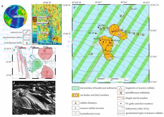
Figure 1.
(a,b) Location of the Irinovskoe HSF within the Mid-Atlantic Ridge; (c), interpretation of structure and geological relationships in the HSF area after [22] (an approximate position of the hydrothermal field is marked by a red triangle); (d) three-dimentional perspective view looking NW of active striated detachment surface emerging from axial valley floor after [22]; (e) schematic map of the HSF, simplified after an unpublished in-house PMGE report, 2011.
According to TV observations of 2011, the Irinovskoe HSF 350 × 380 m in size includes two massive sulfide bodies 3–5 m high, which consist of sulfide edifices with smoker chimneys and products of their erosion surrounded by metalliferrous sediments (Figure 1) [23]. Only strongly chloritized basalts with sulfide dissemination were collected together with massive sulfides in the area of the Irinovskoe HSF. The 230Th/U age of massive sulfides is 58,000–8000 ka [24].
In 2013, the Irinovskoe HSF was explored with an automatic underwater vehicle (AUV) and a remotely operated vehicle (ROV) during the ODEMAR cruise on the R/V “Pourquoi Pas?” [25,26]. Two sites of high-temperature black smoker venting, Active Pot and Pinnacle Ridge, were surveyed with the ROV. Both show black smoker fluids venting at ~365 °C from 1 to 2 m high cauldron-shaped structures with large exit orifices (several decimeters in diameter). Each site consisted of a single, vigorously venting short chimney at the top of a small, elongated sulfide mound. Very little diffuse flow was observed, and no mussel beds were present. Shrimp and bacterial mats were located on or directly next to the active chimneys. Abundant inactive and toppled sulfide chimneys occur in the region surrounding the two active sites, indicating more widespread venting at this site in the past.
3. Materials and Methods
Samples from the Irinovskoe HSF were collected during the 34th cruise of the R/V Professor Logatchev on August 31, 2011 from a water depth of 2791 m using a TV-grab station 34L241 (hereinafter, st. 241; 13°19,957’ N, 44°54,679’ W) (unpublished PMGE report, 2011) positioned in the NW part of ore body I (Figure 1). The station grabbed a large fragment of an extinct sulfide structure weighing more than 100 kg. The bottom of the sulfide fragment measured 65 × 25 cm and the height reached 75 cm.
The textures, structures and preliminary mineralogy of sulfide samples were first examined on-board. The laboratory studies, excluding electron back-scattered diffractometry (EBSD), were carried out at the Institute of Mineralogy (IMin), South Urals Federal Research Center of Mineralogy and Geoecology UB RAS, Miass, Russia. The samples were studied on an Axiolab (Carl Zeiss) optical microscope and a REMMA-202M scanning electron microscope (SEM) equipped with a LZ-5 Link ED-System at a 1-µm electron beam, a 0.6-nA beam current, a 20-kV accelerating voltage (30 kV accelerating voltage in case of native gold) and a counting time of 120 s for peak (standard MINM-25-53, ASTIMEX Scientific Limited, mineral mount no. 01-044). The detection limit for elements was 0.20%. The using of SEM/EDS analysis in studies of Zn-rich chimneys of the Irinovskoe HSF with complex textures involving fine-grained aggregates was warranted by the high SEM/EDS detection efficiency, which permits analysis at a low current and an easier study of minerals unstable in the case of electron bombardment [27]. The possible overlappings (Pb and S or As and Pb) were avoided by using different analytical lines, for example, the As content of As-bearing galena was analyzed using As Lα line because of the overlapping Pb Lα and As Kα lines. The chemical composition of minerals, which are shown in Figures 3–10 and Supplementary Figures S1-1–-54, is presented in Tables 2–7 and Supplementary Tables S1–S9, respectively.
The bulk mineral composition of four samples drilled from Zn-rich chimneys was refined on a SHIMADZU XRD-6000 diffractometer with a Cu anode and a graphite monochromator. The mineral contents were recalculated by the SIROQUANT V4 software with the Rietveld method.
The Fe content of bulk sulfide samples was analyzed using titrimetry and the Cu, Zn, Cd, Pb, Co, Ni, Au and Ag contents were analyzed using atomic absorption analysis (AAA) in air-acetylene flame on a Perkin Elmer 3110 spectrometer. Quality control of the analytical procedure was performed by analysis of State Standard Samples of water metal solutions (7256-96 Zn, 7252-96 Pb, 7472-98 Cd, 7265-96 Ni, 7268-96 Co, 7255-96 Cu, and 8402-2002 Ag) and flotation concentrate of Au-bearing ore CZK-3 (2739-83 Au) (Russian Federation). The analytical titrimetry and AAA uncertainties are shown in Table S8.
Selected trace elements (Ti, V, Cr, Mn, Co, Ni, As, Se, Sr, Mo, Cd, Sn, Sb, Te, Ba, Tl, Pb, Bi and U) of bulk sulfide samples were analyzed on an Agilent 7700× quadrupole inductively coupled plasma mass spectrometer (ICP-MS). The spectrometer was calibrated using multielement calibrated solutions (INORGANIC VENTURES, USA, and GSO, Russian Federation) for the entire set of analyzing elements. The metrological control of the analytical quality was supported by using a standard SGD-2a (Russian Federation). Samples were digested in Teflon autoclaves using a mixture of HF, HCl and HNO3 in a SpeedWave microwave digestion system (Berghof, Germany) during a two-stage heating up to 180 °C for 40 min. After digestion, the fluorine complexes were decomposed by a double evaporation of the dry residual with concentrated HNO3 at 110 °C in glassy carbon crucibles. The precipitates were further dissolved in hot 0.5 N HNO3 and reduced to a 100-mL aliquot. All the pure acids used for digestion were additionally purified in a BSB-939-IR apparatus (Berghof, Germany). The ultrapure water (resistivity 18.2 MΩ*cm compensated at 25 °C) used for dilution was deionized in a Simplicity Water Purification System (Millipore, Molshiem, France). The analytical uncertainties on individual-trace elements are ≤5 rel. %. The analytical ICP-MS uncertainties are shown in Table S9.
EBSD studies of Zn-rich sample 241-2/1-11 were conducted at the Resource Center “Geomodel” (St. Petersburg State University (SPbSU), St. Petersburg, Russia) on a HITACHI S-3400N SEM equipped with an OxfordHKL NordLys Nano EBSD detection system. The EBSD mapping was performed at an accelerating voltage of 30 kV, a beam current of 1.5 nA, an exposition of 0.5 s per pattern, averaging two images (when mapping) or 20 images (to obtain individual patterns) and their subsequent processing using a software package Oxford AZtecHKL. To obtain a mechanically undistorted surface, the sample for the EBSD analysis was treated with a direct beam of Ar plasma using an Oxford IonFab 300 etcher at an exposition of 10 min, an angle of 45°, an accelerating voltage 500 V, a current 200 mA and a beam diameter of 4 inches (Nanophotonics Resource Center, Scientific Park, SPbSU).
For S isotopic analysis, the bulk samples from central and marginal parts of Zn-rich chimneys were drilled with a diamond microdrill. The S isotopic composition (δ34S, ‰; Canyon Diablo Troilite) was determined on a Delta+ Advantage, Thermo Finnigan mass spectrometer equipped with an EAFlash 1112 elemental analyzer and ConFloIII interface using NBS-123 (sphalerite, US National Bureau of Standards) as a standard. The analytical error is ±0.12‰. The results were processed in the ISODAT-2.0 program.
To estimate the possible formation conditions of mineral assemblages and the role of various factors affecting the mineral composition (host rocks and magmatic input), we simulated the process of crystallization of mineral assemblages of Zn-rich sulfides of the Irinovskoe HSF by Gibbs energy minimization and local equilibrium in the Selektor software. Because the initial parameters of modeling and their results are closely related, the details of modeling are provided in Section 4.4.
4. Results
4.1. Textures of Massive Sulfides
The sulfide edifice consisted of coalesced Cu-rich chimneys in the central part/basement and Zn-rich chimneys at the margins/top (Figure 2a). The Cu-rich chimneys contain numerous channels filled with opal sinters. The sulfide edifice was oxidized from the surface and covered by up to 0.5 cm thick crusts of ochreous and brown aggregates of Fe- and Mn-oxyhydroxides, locally with minerals of the atacamite group. The diameter of Zn-rich chimneys varied from a few centimeters to 10–15 cm (Figure 2b). The Zn-rich samples were light, sooty, porous and friable (Figure 2c,d). They locally contain small (1 cm max) unsealed channels (Figure 2c), but most Zn-rich chimneys exhibit no channels or clear zonation (Figure 2d). Some chimney fragments that are up to 10 cm across exhibit: (i) A central more porous zone ~1 cm thick (a former channel?); (ii) A surrounding more compact opal–Zn sulfide zone up to 1.5 cm thick rimmed by an almost continuous dense opal–Zn sulfide layer up to 1 mm thick; (iii) A zone of porous opal–Zn sulfide aggregates up to 4 cm thick with a small amount of granular pyrite. More massive Zn-rich sulfide samples are characterized by a higher amount of opal (Figure 2d).
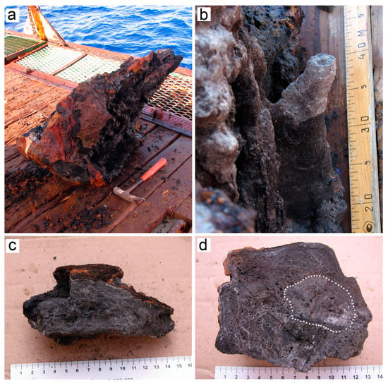
Figure 2.
Massive sulfides of the Irinovskoe HSF: (a) A sulfide edifice collected at st. 241; (b) A clogged Zn-rich chimney at the periphery of the edifice; (c) Porous Zn-rich sample without zonation and central conduits; (d) An unpolished section of Zn-rich chimney with unclear zonation: a more compact inner zone (contoured by white dots) and a more porous outer zone. Brown, Fe-oxyhydroxide crusts. On-board images.
4.2. Mineralogy of Massive Sulfides
The mineral composition of Zn-rich sulfides varies depending on the sampling area, closer to the margins or the central part of the edifice. Macroscopically, only Zn sulfides (~65%), silica (~20%), Fe-oxyhydroxides (~10%) and, locally, pyrite and chalcopyrite (~5% in total) can be recognized in samples. Rare crystals of baryte and secondary copper sulfides are observed under a binocular microscope. According to the X-ray diffractometry (XRD), the mineral composition is dominated by wurtzite (from 3 to 65 wt%) and sphalerite (from 5 to 30 wt%), which are accompanied by pyrite, chalcopyrite, amorphous silica and, locally, native sulfur (Table 1). SEM studies revealed the presence of accessory galena, CdS phase, pyrrhotite, isocubanite, acanthite, various Ag–Cu–Sb(±As)-bearing minerals, covellite, yarrowite, native gold, native sulfur, anglesite, gypsum, smectites, naumannite and lollingite.

Table 1.
XRD-based mineral composition of fragments of Zn-rich chimneys (wt%).
4.2.1. Zn Sulfides
Sphalerite and wurtzite were distinguished on the basis of morphology of their aggregates. All Zn sulfides are intensely replaced by Fe-oxyhydroxides locally mixed with smectites and by Cu sulfides.
The walls of unsealed channels are incrusted by tabular and pyramidal, most likely wurtzite, crystals up to ~0.1 mm in size with striation on edges (Figure 3a and Figure S1-1). These crystals locally overgrow the former tube worms, the interior of which is filled with a mixture of Fe-oxyhydroxides and smectites (Figure 3b). In polished specimens, the wurtzite crystals exhibit hexagonal sections (Figure 3c) and a zoned–sectorial structure with higher (11.75–18.75 wt%) and lower (2.97–7.64 wt%) Fe contents in the cores and rims, respectively (Figure 3c; Table 2 and Table S1). Wurtzite is locally replaced by low-Fe (2.97 wt%) Cd-bearing (up to 5.50 wt% Cd) most likely sphalerite with darker color and lower reflectivity (Figure 3d,e and Figures S1-2,-3; Table 2 and Table S1).
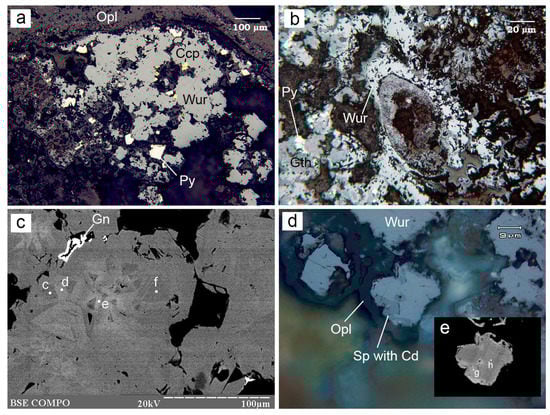
Figure 3.
Morphology of wurtzite from the Irinovskoe HSF: (a) Crystalline wurtzite (Wur) among opal (Opl) with pyrite (Py) and chalcopyrite (Ccp) crystals on top; (b) Transverse section of a tube worm filled with Fe-oxyhydroxides (Gth) and overgrown by wurtzite; (c) Zoned–sectorial wurtzite crystals (SEM/EDS points (hereinafter, points) c–f) with high- and low-Fe zones overgrown by galena (Gn); (d) Wurtzite rimmed by opal and replaced by a Cd-bearing sphalerite (darker rim) with lower reflectivity; (e) Detail of the previous image: Fe-rich wurtzite (point h) replaced by a Cd-bearing sphalerite (point g). Images: reflected light (a,b,d); BSE (c,e). Sample numbers: 241-2/1-11 (a,c–e), 241-2/2-5 (b). Hereinafter, the mineral abbreviations follow the recommendations of [28].
Table 2.
Selected chemical composition of Zn sulfides from the Irinovskoe HSF, wt%.
Abundant dendrites, which grow toward the margins of the chimneys, are most likely made up of sphalerite (Figure 4a and Figure S1-4). Closer to the margins of the chimneys, sphalerite and opal compose zoned spherulitic aggregates with several alternated zones and interstitial galena (Figure 4b and Figures S1-5–S1-7). The central and marginal zones are made up of opal, whereas sphalerite occupies an intermediate position. The sphalerite zones, a few micrometers thick in the central and intermediate parts, are composed of chains of the tiniest grains. A penultimate zone 20–30 µm thick consists of radial sphalerite intergrowths locally with reniform morphology (Figure 4c and Figure S1-8). The reniform aggregates are composed of two sphalerite types: a core of up to 40 µm across enriched in Pb (8.57–9.55 wt%) and Ag (1.83–2.56 wt%) and a rim of up to 5 µm thick depleted in Pb (up to 1.37 wt%) and Ag (0.37–0.48 wt%) (Table 2 and Table S1).
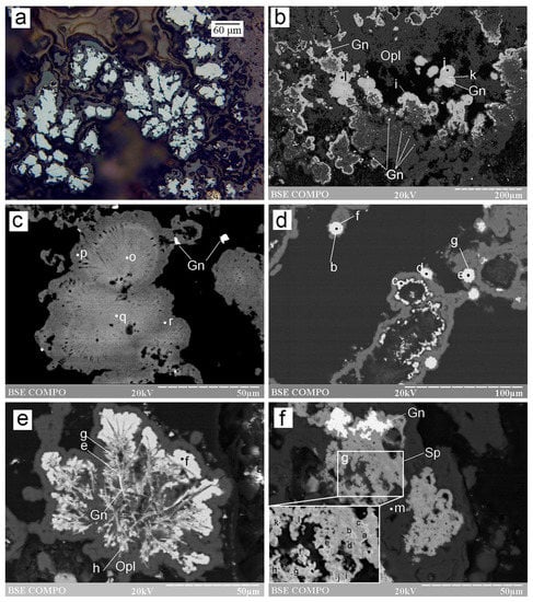
Figure 4.
Morphology of sphalerite from the Irinovskoe HSF: (a) Dendritic sphalerite rimmed by opal with tiny pyrite grains; (b) Zoned opal–sphalerite aggregates with reniform sphalerite and galena crystals on top and numerous galena inclusions in opal; (c) Zoned reniform sphalerite aggregate with a Pb- and Ag-rich center and a Pb- and Ag-poor rim; (d) Sphalerite framboids (points b, f, g and e) rimmed by opal (point c); (e) Dendrites of Fe-, Cd-, Co- and Pb-bearing acicular sphalerite (points g and e) and galena overgrown by Fe-rich crystalline sphalerite (points f and h); (f) Anhedral Cd-rich sphalerite aggregates (Sph) with galena (bright) surrounded by opal ( point m); (g) Detail of the previous image: veinlets of sphalerite with high Cd contents (all points except for a and d) in sphalerite with lower Cd contents (points a and d). Images: reflected light (a); BSE (others). Sample numbers: 241-2/1-11 (a–c,f,g), 241-2/2-2 (d,e).
Sphalerite is also observed as microcrystals and their aggregates or loosely/densely packed framboids 10 µm in diameter surrounded by opal (Figure 4d and Figure S1-9). The microcrystals and framboids can contain Pb, Ag and Cu (Table 2 and Table S1). The framboidal aggregates are characterized by a Pb-rich core (up to 6.66 wt%) and a Pb-free margin (Table 2 and Table S1).
Acicular sphalerite crystals 1–2-µm thick form dendrites or skeletal aggregates, which replace radial aggregates of acicular native sulfur (Figure 4e). Acicular sphalerite is overgrown by fine-crystalline sphalerite and acicular galena (Figure 4e) and contains the high amounts of Fe, Cd, Co and Pb (Table 2).
Anhedral sphalerite aggregates of up to 50 µm in size within opal are made up of isometric grains max 5 µm in size (Figure 4f and Figure S1-10–-12). This low-Fe (<4.48 wt%) sphalerite contains 13.85–17.48 wt% Cd and is surrounded by rims or is cut by the finest veinlets of Cd-rich sphalerite (20.09–41.38 wt%) (Figure 4g) (Table 2 and Table S1).
The Zn sulfides of different morphology exhibit different correlation coefficients between the main chemical elements (Table S2). Wurtzite, framboidal and microcrystalline sphalerite have the highest negative Zn–Fe correlations. In contrast, Cd-poor and Cd-rich reniform and anhedral sphalerite is characterized by the highest negative Zn–Cd correlations. The negative Fe–Cd correlation is characteristic of anhedral sphalerite, whereas the reniform one exhibits negative Fe–Ag and Fe–Pb and positive Ag–Pb correlations.
The EBSD studies of dendritic sphalerite revealed its polycrystalline structure (Figure S2-1a–-1c). According to pole figures, these aggregates are chaotically oriented (Figure S2-1d). The maps in Euler colors show that the aggregates are composed of chaotically oriented smaller crystals in the central parts and larger crystals in the margins (Figure S2-2a–-2c). The inclusions of galena and wurtzite in sphalerite exhibit the same orientation as sphalerite (Figure S2-1c). The Kikuchi patterns of some Cd-rich Zn sulfide grains correspond to sphalerite at the coincidence level of 9 to 12 bands out of 12 with a mean angle deviation (MAD) less than 1° (minimum 0.48°) (Figure S2-3).
4.2.2. Cd Sulfides
The Cd sulfide occurs as several morphological and geochemical types (Figure 5). The smallest (<1–10 µm) anhedral grains, subhedral crystals or microcrystalline intergrowths are found on top of sphalerite or opal aggregates (Figure 5a,b, Figures S1-3, S1-10 and S1-13–-15). This CdS type contains a low amount of Zn (0.81–2.25 wt%) and Fe (max 2.05 wt%), but a significant amount of Cu (0.42–6.73 wt%) and Ag (2.09–21.01 wt%) (Table 3 and Table S3).
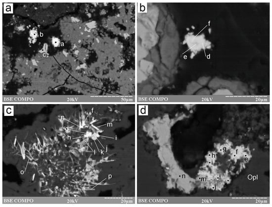
Figure 5.
Morphology of a CdS phase from the Irinovskoe HSF: (a) Anhedral CdS grains (points a and b) between sphalerite aggregates (point c) replaced by Fe-oxyhydroxides (gray); (b) Microcrystalline aggregate of an Ag-rich CdS phase (points e, d and f) on top of sphalerite replaced by Fe-oxyhydroxides; (c) Pseudomorphic replacement of fine-platy pyrrhotite (points l, o and p) and granular sphalerite (points k and j) by CdS phase (points f, g, h, i, m and n) in opal; (d) Spongy aggregate of CdS phase (all points except for l and n) and Ag sulfide (point l) after anhedral high-Fe Cd-free sphalerite (point n). BSE images. Sample numbers: 241-2/2-5 (a,b); 241-2/2-2 (c); 241 (d).
Table 3.
Selected chemical composition of the CdS phase from the Irinovskoe HSF, wt%.
In samples with native sulfur, the CdS phase pseudomorphically replaces acicular pyrrhotite and granular sphalerite (Figure 5c and Figure S1-16). It has higher Zn contents (13.76–23.07 wt%) and a variable amount of Fe (0.00–10.81 wt%), but is free from Cu and Ag (Table 3 and Table S3). The CdS phase locally forms spongy aggregates, which replace sphalerite and are associated with an Ag sulfide (Figure 5d). This CdS phase exhibits the highest Zn (21.24–25.27 wt%)/Ag (0.00–7.04 wt%) and lowest Fe (0.47–1.47 wt%) contents (Table 3). The spongy aggregates are locally characterized by higher S contents possibly originating from host sphalerite (Table 3).
4.2.3. Fe Sulfides and Fe Arsenide
The Fe sulfides include pyrite, marcasite and pyrrhotite. Pyrite most often forms small (~50 µm) crystals and their intergrowths around Zn sulfides, locally, in assemblage with chalcopyrite (Figure 3b). The amount of pyrite increases toward the margins of chimneys, where its fine-crystalline, laminar, dendritic or reniform aggregates mostly occur in opal (Figure 6a). Rare crystalline pyrite–marcasite aggregates (~150–200 µm) are rimmed by marcasite crystals (Figure 6b). Pyrite framboids ~5 µm across are observed on top of radial baryte aggregates (Figure 6b). At the margins of chimneys, fragments of tube worms up to 150 µm long and ~50 µm across are partly replaced with opal and mantled by fine-crystalline pyrite. Another type of most likely biosignatures includes filaments max 50 µm long and a few micrometers thick, which are composed of opal and are overgrown by fine pyrite crystals (Figure 6c).
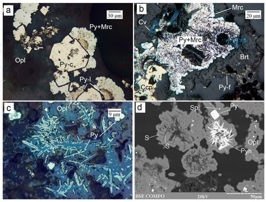
Figure 6.
Morphology of Fe sulfides from the Irinovskoe HSF: (a) Crystalline pyrite (Py-c) overgrown by reniform pyrite composed of the laminar core (Py-l) and radial pyrite–marcasite rim (Py+Mrc) in opal; (b) Crystalline pyrite–marcasite aggregate (Py+Mrc) with a marcasite rim overgrown by baryte (Brt) and framboidal pyrite (Py-f); (c) Opal filaments overgrown by fine-crystalline pyrite; (d) Lattice aggregates of acicular pyrrhotite and native sulfur (S), crystalline pyrite and sphalerite grains in opal. Images: a–c, reflected light; d, BSE image. Sample numbers: 241-2/2-2 (a,d), 241-2/4-1 (b); 241-2/2-5 (c).
Pyrrhotite was found in samples with native sulfur, where it forms lattice aggregates of acicular crystals ~2 µm thick or anhedral inclusions in pyrite crystals (Figure 6d).
Two platy lollingite grains 5 × 2 µm in size were found aroundy a platy As-bearing galena crystal between opal coatings on sulfides (Figure S1-17). Lollingite contains 1.89 wt% Zn and 0.84 wt% S; its formula, based on an anion sum of two, is (Fe0.95Zn0.06)1.01(As1.94S0.06)2.00.
4.2.4. Cu–Fe and Cu Sulfides
The Cu–Fe sulfides include isocubanite and chalcopyrite. Isocubanite occurs as euhedral to subhedral crystals up to 50 µm in size, which are arranged along the unsealed channels and overgrown by pyrite and wurtzite crystals (Figure 7a). Isocubanite crystals contain a lattice of chalcopyrite lamella about 1 µm thick. Chalcopyrite also forms subhedral crystalline aggregates up to 50 µm in size, which either overgrow Zn sulfides or are surrounded by them (Figure 3b, Figure 6b and Figure 7a,b). Locally, chalcopyrite is observed as filaments of up to 50 µm long and 5 µm thick (pseudomorphoses after tubular microorganisms?) (Figure S1-18). Both isocubanite and chalcopyrite contain Zn and are characterized by a Cu deficit and a Fe + Zn excess (Table S4).
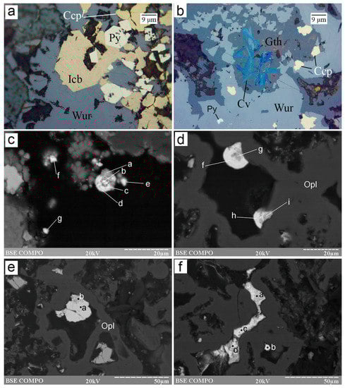
Figure 7.
Morphology of Cu–Fe and Cu sulfides from the Irinovskoe HSF: (a) Euhedral isocubanite (Icb) and pyrite crystals overgrown by wurtzite; (b) Acicular covellite crystals in Fe-oxyhydroxides, which replace wurtzite; (c) Spherules of Ag- and Cd-bearing covellite (point a), Cu- and Cd-bearing acanthite (points b, c and f) and an Ag- and Cu-bearing CdS phase (points d, e and g); (d) Spherules of Ag- and Sb-bearing covellite (points g and i) and As-bearing Cu–Ag–Sb sulfosalt (“stephanite”) (points h and f); (e) An intergrowth of hexagonal-shaped crystal of Ag-rich Sb-bearing Cu sulfide (point b) replaced by Cu-bearing Ag–Sb sulfosalt (“pyrargyrite”) (point a); (f) A veinlet of Ag-rich Sb-bearing covellite (point a) replaced by Cu-bearing Ag–Sb sulfosalt (“argentotetrahedrite-Zn”) (points b, c and d) in opal. Images: a,b, reflected light; c–f, BSE image. Sample numbers: 241-2/2-5 (a–c), 241 (d–f).
Several morphological and chemical types are recognized for Cu sulfides. According to the metal/sulfur ratio, they mostly consist of covellite. Radial-shaped bunches of acicular covellite crystals a few micrometers thick replace Zn and Cu–Fe sulfides and Fe-oxyhydroxides (Figure 6b, Figure 7b and Figure S1-19,-20). This covellite is nearly stoichiometric and contains Fe (5.75–9.36 wt%) and a minor amount of Zn (0.64–1.08 wt%) and Ag (0.58–0.92 wt%) (Table 4 and Table S4). Extremely small (~5 µm) spherical covellite grains in assemblage with acanthite and CdS phase occur on top of opal, locally, forming spherules with alternating zones of these minerals (Figure 7c and Figure S1-21). This covellite contains 8.02–14.33 wt% Ag, 2.60–4.26 wt% Fe and, locally, 2.91 wt% Cd (Table 4).
Table 4.
Selected chemical composition of Cu sulfides from the Irinovskoe HSF, wt%.
Another type of spherical aggregate is also found on opal and is composed of covellite and Cu–Ag–Sb sulfosalts, which overgrow and replace covellite (Figure 7d and Figures S1-22–-25). This covellite contains a higher amount of Ag (4.80–20.50 wt%), as well as Sb (2.89–5.92 wt%) and Zn (0.00–1.96 wt%) (Table 4). Iron (0.46 wt%) and Cd (0.47 wt%) were detected in single analyses. Both Ag-rich covellite types locally exhibit deficit in metals.
Some interstitial granular aggregates between opal or veinlets 10 µm thick and 50 µm long in opal are also made up of Cu sulfides and are locally replaced by Cu–Ag–Sb sulfosalts (Figure 7f and Figure S1-24,-38). These Cu sulfides exhibit a lower S content (21.53–26.97 wt%) in comparison with covellite and extremely high Ag contents (33.00–40.67 wt%) and also contain Sb (2.63–17.45 wt%) (Table 4 and Table S4). Two analyses are well recalculated to the formula of yarrowite Cu9S8 (Table 4).
4.2.5. Pb Sulfides
The Pb sulfides include galena and its As-bearing variety. Galena forms small euhedral to subhedral crystals and their aggregates around Zn sulfides, inclusions in opal and anhedral aggregates with sphalerite (Figure 3e, Figure 4b,c,f and Figure S1-26,-27). In samples with native sulfur, galena pseudomorphically replaces acicular CdS crystals (Figure 4e). Galena is characterized by a stoichiometric composition (Table S4).
The As-bearing galena forms spongy anhedral grains, which occur in opal, and locally replaces As-free galena or sphalerite (Figure 8a and Figure S1-28–-31). The As content reaches 8.20 wt% (Table 5) and exhibits a negative correlation with Pb content (r = –0.99). These galena grains are replaced by an As2O3 phase from the rims (Figure 8b and Figure S1-28–-31).
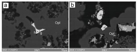
Figure 8.
Morphology of As-bearing galena and Ag–Sb–Cu sulfosalts from the Irinovskoe HSF: (a) Interstitial aggregate of Pb–As–Cu-bearing Ag–Sb sulfosalts, the compositions of which can be recalculated to “pyrargyrite” (point i), “argentotetrahedrite-Zn” (point h) and “miargyrite” (point g); (b) Reniform aggregates of As-Cu-bearing Ag–Sb sulfosalt (“pyrargyrite”) (points k and l) on opal. BSE images. Sample 241.
Table 5.
Chemical composition of As-bearing galena from the Irinovskoe HSF, wt%.
4.2.6. Noble Metal Mineralization
The noble metal mineralization includes Ag–Sb–Cu sulfosalts, Ag sulfides, naumannite and native gold. The Ag–Sb–Cu sulfosalts occur as interstitial aggregates or veinlets in opal and anhedral grains, euhedral crystals or spherulitic aggregates 20 µm max on top of opal (Figure 7d–f, Figure 8 and Figure S1-33–-39). In most cases, these minerals replace covellite. The zoned spherulitic aggregates exhibit atoll-like structure with a Ag-rich Sb-bearing covellite in the central zones and Ag–Sb–Cu sulfosalts in the rims. The Ag–Sb–Cu sulfosalts demonstrate a variety of nonstoichiometric compositions (Table 6 and Table S5). Their composition is dominated by Ag, which is followed by Sb and then Cu. Some analyses can approximately be recalculated to formulas of miargyrite, pyrargyrite, stephanite and argentotetrahedrite-Zn (Table 6).
Table 6.
Selected chemical composition of Ag–Sb–Cu sulfosalts from Zn-rich chimneys of the Irinovskoe HSF, wt%.
Acanthite is observed between opal, sulfides or Fe-oxyhydroxides as: (i) Anhedral knobby aggregates, which are locally associated with Ag-bearing covellite and replace sphalerite together with covellite; (ii) Crystalline aggregates; (iii) Spherulitic aggregates together with Ag- and Cd-bearing covellite and CdS phase; (iv) Spherulitic aggregates and fine-acicular crystals in assemblage with interstitial Ag- and Sb-bearing covellite (Figure 7c, Figure 9a–d and Figure S1-40–-42). Two geochemical types of acanthite are recognized: (i) Cu-, Zn- and Fe-bearing associated with Ag-bearing covellite and (ii) Sb-, Cu- and Zn-bearing associated with Ag- and Sb-bearing covellite (Table 7).
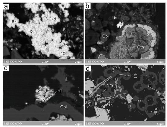
Figure 9.
Morphology of Ag-rich sulfides and native gold from the Irinovskoe HSF: (a) Interstitial knobby aggregate of acanthite (points a–d); (b) Star-shaped crystalline acanthite aggregate (point a) on opal around sphalerite (point b); (c) Bladed Sb–Cu-bearing acanthite crystals (points d–g) with interstitial Ag–Sb-bearing covellite (points c and h); (d) Naumannite grain (Nm) on top of covellite (point d) and opal and inclusions of native gold (point a) at the boundary of sphalerite and opal. BSE images. Samples: 241-2/2-5 (a,b), 241 (c), 241-2/3-2 (d).
Table 7.
Chemical composition of acanthite from the Irinovskoe HSF, wt%.
The composition of some Ag-rich Cu–Sb-bearing grains cannot adequately be recalculated to a particular mineral species, most likely because of the extremely fine mixtures of associated Cu sulfides, Cu-bearing Ag–Sb sulfosalts and acanthite (Table S7). These phases also occur as the smallest (max 5 µm) grains on top of opal, or are also associated with Ag–Sb-bearing covellite in reniform aggregates, where they replace covellite (Figure 9d).
One small (max 3 µm) naumannite grain was found on top of covellite and opal around sulfides (Figure 9d). The mineral contains S, Fe, Zn and Cu, which are probably acquired from the adjacent covellite. Abundant small (2 µm) native gold grains occur: (i) In/on opal (Figure 9d); (ii) At the contact of opal and fine-crystalline pyrite or sphalerite; (iii) In Fe-oxyhydroxides; (iv) In smectites, which overgrow Zn sulfides and are replaced by Fe-oxyhydroxides. Native gold has a high Ag content varying from 15.00 to 48.43 wt%.
4.2.7. Non-Sulfide Minerals
The non-sulfide minerals include major opal, abundant Fe-oxyhydroxides and subordinate to rare baryte, native sulfur, anglesite, gypsum, smectites and Mn-oxyhydroxides. Opal occurs as: (i) Rare elongated bunchy needles up to 4–5 mm long, which are directed toward the center of the unsealed channels (Figure 10a), and (ii) More abundant spherical aggregates or thin films and crusts on sulfides or interstitial massive aggregates between sulfides (Figure 4, Figure 5, Figure 6, Figure 7, Figure 8, Figure 9, Figure 10b and Figure S1). Opal contains SO3 (0.26–1.64 wt%), FeO (0.24–1.67 wt%), ZnO (0.43 wt%) and Al2O3 (up to 11.99 wt%).
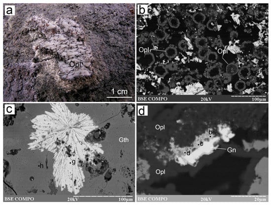
Figure 10.
Morphology of some non-sulfide minerals from the Irinovskoe HSF: (a) Opal sinters in a channel of a Zn-rich chimney; (b) Opal “donuts” on sulfides; (c) Radial baryte aggregate (point g) in Fe-oxyhydroxides (point h); (d) Galena grains replaced by anglesite (points b–d). On-board photo (a), BSE images (b–d). Samples: 241-2/3-2 (b), 241-2/2-5 (c), 241-2/2-2 (d).
The Fe-oxyhydroxides form thin crusts on the sulfide edifice (Figure 2a,d–f) and replace all sulfides (Figure 4c,d, Figure 5a, Figure 6c, Figure 7b, Figure 9b and Figure S1-43,-44). The chemical composition of Fe-oxyhydroxides depends on the replaced minerals. All Fe-oxyhydroxides contain SiO2, Al2O3, ZnO, SO3 and Cl (Table S6). The Fe-oxyhydroxides after opal are enriched in SiO2 (15–18 wt%) (Table S6). Those developed after sulfides can contain a higher amount of SO3, ZnO, CuO and Ag2O (Table S6). The Fe-oxyhydroxides from the outer crusts also contain MgO (up to 1.10 wt%), P2O5 (up to 2.08 wt%), CaO (up to 0.64 wt%) and PbO (up to 0.79 wt%). The Fe-oxyhydroxides intergrown with Mn-oxyhydroxides in the outermost areas of the crusts also contain MnO (up to 8.20 wt%), K2O (up to 0.34 wt%), V2O5 (up to 0.73 wt%), CoO (up to 0.42 wt%) and TiO2 (up to 0.42 wt%) (Table S6).
The Mn-oxyhydroxides replace Fe-oxyhydroxides at the margins (Figure S1-45,-46). Based on XRD studies, todorokite is the most likely Mn-bearing phase. The composition of Mn-oxyhydroxides reflects a fine mixture with Fe-oxyhydroxides (Table S6). These aggregates also contain ZnO (up to 11.52 wt%), SO3 (up to 6.87 wt%), SiO2 (up to 7.19 wt%), Al2O3 (up to 1.74 wt%), NiO (up to 0.32 wt%) and K2O (up to 0.66 wt%). The latter has a positive correlation with SO3 (r = 0.95).
Baryte is abundant in the outermost Fe-oxyhydroxide crusts, where it forms radial aggregates ~100–150 µm across (Figure 10c and Figure S1-47,-48). It also occurs as radial aggregates on sulfides (Figure 6b) or single platy crystals, 20 µm long and ~5 µm wide, on top of opal rims around sulfides (Figure S1-49). Baryte contains SrO (5.32–6.04 wt%), FeO (0.59–1.06 wt%) and CaO (0.35–0.75 wt%) (Table S7).
Native sulfur forms radial aggregates of acicular crystals, ~10 µm long and ~2 µm wide, that are surrounded by opal and replaced by pyrrhotite, sphalerite (including Cd-bearing variety) and galena (Figure 6f and Figure S1-50–-52). The acicular morphology is indicative of its monoclinic state. Anglesite was found as small anhedral porous aggregates, which replace galena crystals (Figure 10d; Table S7).
The Al-rich smectites form anhedral aggregates around sulfides and are overgrown by opal or replaced by Fe-oxyhydroxides (Figure 3d). Their chemical composition is dominated by SiO2 (50.42–53.71 wt%) and Al2O3 (23.85–28.17 wt%) with a subordinate amount of FeO (4.33–5.42 wt%) and a minor content of K2O (0.32–0.75 wt%), CaO (0.24–0.46 wt%), ZnO (0.65–1.22 wt%) and SO3 (0.43–0.65 wt%) and correspond to a mixed-layered kaolinite–smectite clay mineral.
4.3. Chemical and S Isotopic Composition of Zn-Rich Massive Sulfides
Depending on the position of the samples (closer to the margin or the center of the sulfide edifice), the contents both of main and trace chemical elements significantly vary (Table 8 and Table 9). The Zn-richer samples (241-2/2, 241-2/3) are characterized by the highest Cd, Pb, Co, Au, Ag, As, Sn, Sb, Ba and Tl contents, whereas the Cu-richer sample (241-1/1) has the highest Co, Ge, Se, Te and Bi contents.
Table 8.
AAA-based contents of chemical elements of Zn-rich smoker chimneys from the Irinovskoe HSF (ppm).
Table 9.
ICP-MS-based contents of chemical elements of Zn-rich smoker chimneys from the Irinovskoe HSF (ppm).
The S isotopic composition of bulk Zn-rich samples is negative and varies from –0.04 to –1.59‰ with an average value of –0.59‰ (Table 10).
Table 10.
S isotopic composition of bulk samples of Zn-rich chimneys from the Irinovskoe hydrothermal sulfide field.
4.4. Physicochemical Modeling
In physicochemical modeling, we used a multisystem, which was previously applied for the calculations of basalt/seawater and peridotite/seawater (rock/seawater = R/SW) interaction [10,31,32] including Ag, Al, As, Au, B, Ba, Bi, Br, C, Ca, Cd, Cl, Co, Cr, Cu, F, Fe, H, I, K, Mg, Mn, N, Na, Ni, O, P, Pb, S, Sb, Se, Si, Te, Ti, Tl and Zn. The system was expanded by thermodynamic data of miargyrite, pyrargyrite [33,34] and enargite [35]. The coefficients of the heat capacity equation for enargite (Cp (cal·mol−1·K−1) = 48.334 − 1.921 × 10 × T−0.5 + 0.069 × 10³ × T−1) were calculated in the Selektor software. Pyrolusite, bixbyite and hausmannite were excluded from calculations because the Mn concentration in the solution under oxidized conditions depends on the presence of Mn-oxyhydroxides Mn(OH)2 and MnOOH. Because the thermodynamic data on hawleyite are unavailable, only greenockite was present in calculations. Both sphalerite and greenockite were included as mineral phases rather than solid solutions.
Two scenarios of R/SW interaction were calculated. Scenario I includes the change in the chemical composition of the multisystem depending on the R/SW ratio (ξ), following a scheme of Helgeson [36], in which the R/SW ratio was given by the addition of a variable amount of a solid matter to 1 L seawater according to a logarithmic law (log10) with a step of 0.01. Scenario II uses a flow reactor model, where the fluid, which reacted with solid phases, moves to the next reservoir in the same multicomponent system [37,38]. Seawater and reactant rock compositions [39,40,41,42] are reported in Table S10. To estimate a possible magmatic input, magmatic gas (10 g) of the Erta Ale basaltic volcano was added to the initial composition of basalt and peridotite that corresponds to the concentration of H2O saturation of 1% of the fluid concentration in basaltic magma [43].
In calculations, we first modeled an interaction of basalt and peridotite with seawater at temperatures of 350 and 400 °C (typical of high-temperature black smokers [44]) and a pressure of 50 MPa (below the critical point of seawater) [45]. These conditions correspond to ~5000 m of a water column pressure, which is 2200 m below the seafloor in the area of the Irinovskoe HSF. These conditions result from the heating of watered rocks in a temperature field above a magmatic chamber [46]. To model the mineral assemblages most close to natural ones, the ξ value varied from –5 to 1. It was found that these mineral assemblages match the alteration of basalts at a ξ value of 0.2. Further modeling was conducted according to scenario II with conductive cooling of the fluid from 350 and 400 to 2 °C (a temperature of ambient seawater) and a step of 10 °C without interaction with any solid phases, which imitates the process of penetration of fluid in a free porous space of the smoker chimney. The Bi, Cr, Mo, P and Ti minerals (apatite, bismuthinite, magnesiochromite, ilmenite, rutile, titanite, molybdenite and chromite), which are present in solutions, were removed from consideration because their presence has a minor effect on the geochemical properties of the system.
Our calculations showed that a hematite + anhydrite + brucite + chrysotile + chlorite assemblage of secondary minerals is typical of both rock types at the lower ξ values (= a strong “washing” by heated seawater) (Figure S3). With the increasing ξ values, the oxidation conditions change by reducing conditions at the ξ values of –3.24 and –3.0 for peridotite and basalt, respectively, which is clearly registered in each case by a drop in Eh values of the system (Figure S3a,a’).
In a range of the intermediate ξ values (−3 < ξ < −1.7), the altered basalt is host to an anhydrite + quartz + amesite ± talc ± smectite assemblage. Anhydrite precipitates from seawater during its heating. The increase in the ξ values at high negative Eh values leads to the disappearance of anhydrite, quartz, talc and hematite and the stability of magnetite, montmorillonite, actinolite, sodic plagioclase, smectites, epidote and sulfides (pyrite, pyrrhotite, chalcopyrite, sphalerite, greenockite, kullerudite, clausthalite, linnaeite–polydymite and cattierite).
The peridotite/seawater system at the ξ values of <−3 typically contains anhydrite + hematite + chrysotile + chlorite (Figure S3). An anhydrite + chrysotile + chlorite + hematite ± magnetite ± talc ± linnaeite–polydymite ± cattierite ± vaesite assemblage is typical of a range of −3.0 < ξ < −1.5. At the ξ values of >−1.5, the system contains chrysotile, chlorite, actinolite, diopside, magnetite ± phlogopite and sulfides (Figure S3d’), but is free from anhydrite, hematite and talc. The ξ values of >0 are favorable for the formation of phlogopite, biotite, tetra-auricupride, auricupride, native silver and chalcocite. These mineral assemblages are generally consistent with those in naturally altered basalts and peridotites and with the results of experiments and thermodynamic modeling of R/SW interaction (e.g., [47,48,49,50,51]).
We also monitored the extraction and behavior of elements in the fluid (Figure S3b,b’) depending on the ξ values. The concentration of nearly all elements decreases with the formation of the solid phases in the reaction products: see, e.g., a gradual decrease in Zn and Cd contents at the corresponding precipitation of sphalerite and greenockite. The maximal contents of Cd (2.89 × 10⁻⁶ moles) for ξ = 0.34 and Zn (2.18 × 10⁻³ moles) for ξ = 0.18 are observed in the basalt-related system. Note that the Fe content of the solution is constant under oxidation conditions and strongly increases at a decreasing Eh. The maximal Fe content (8.65 × 10⁻⁴ moles) is achieved in the basalt-related system at ξ = −2.13, then gradually decreases to ~(2.5–4.8) × 10−5 moles. Chloride complexes are predominant for Cd and Zn in the entire range of ξ values: CdCl20 and ZnCl3−, respectively. A similar behavior of Cd, Zn and Fe is observed in the peridotite-related system.
The modeling of conductive cooling of the solution, which is a result of the above basalt/seawater reaction, imitates the penetration of ore-forming fluid through a wall of a smoker chimney (Figure 11). The first minerals to precipitate at high temperatures in the basalt-related system (Figure 11a) are chalcopyrite and pyrite. Further cooling to 310 °C leads to the precipitation of dominant sphalerite, amorphous silica (<270 °C) and covellite, which replace chalcopyrite. The low temperatures (<70°) are favorable for the precipitation of native sulfur. The temperature of precipitation of Cd, Pb, Sb, Ag, As and Se sulfides is proportional to their content in the initial composition of reacting substances (the total amount of the mineral can be estimated from the plot). Greenockite can precipitate in a range of 210–100 °C (Figure 11a). Its minimal amount (n × 10−8 moles) precipitates at temperatures of 30–50 °C during the cooling of the fluid reacted with basalt for ξ = −1.15 (R/SW = 0.07). All calculations contain montmorillonite. The behavior of the basalt-related system with the involvement of magmatic gas is generally similar to the above described, but is terminated by the precipitation of baryte and orpiment (Figure 11b,d). The formation of greenockite is shifted toward the higher temperatures due to the addition of Cd from magmatic gas.
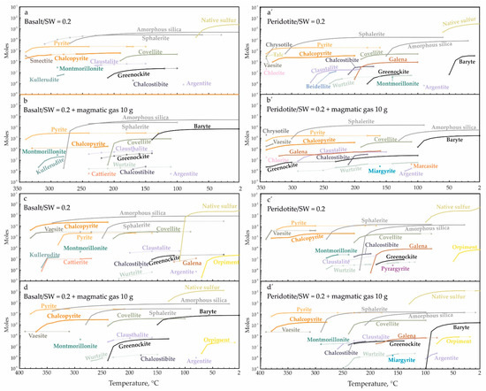
Figure 11.
Amount of minerals precipitated from the solution reacted with basalt (a–d) and peridotite (a’–d’) at temperatures from 350 (a,a’,b,b’) and 400 (c,c’,d,d’) to 2 °C with a step of 10 °C. The plot lines reflect the accumulating total. The discontinuous precipitation or the absence of minerals in a temperature range are marked by solid and dotted lines, respectively.
The behavior of the peridotite-related system is similar to that of the basalt-related system (Figure 11), but amorphous silica starts to precipitate below 210 °C and montmorillonite at 350 °C is accompanied by talc, chrysotile and chlorite (Figure 11a’). The Ag–Sb sulfosalts are precipitated only in the peridotite-related system below 180 °C (miargyrite and pyargyrite with and without magmatic gas, respectively) (Figure 11b’,d’). Greenockite forms at 180–130 °C that is 30 °C lower than in the basalt-related system and at 80 °C at the same minimal ξ values. The low-temperature area (<110 °C) in both systems is characterized by the formation of native sulfur.
5. Discussion
5.1. Sequence of Mineral Formation and Mineralogical Curiosities
The studied Zn-rich smokers of the Irinovskoe HSF with poorly discernable conduits (or their absence) and porous structures are similar to many Zn-rich chimneys from other seafloor HSFs. These morphological features indicate a comparatively lower flow velocity of circulating lower-temperature fluids when the channel-ways are easily clogged by mineral precipitates during sluggish flow [2,9,52]. The samples also exhibit a number of mineralogical curiosities, which indicate the abundance of different local formation conditions leading to the crystallization of diverse accessory mineralization.
The schematic paragenetic sequence of mineral formation of Zn-rich chimneys can tentatively be divided into four temperature-related stages: high (>300 °C), moderate (<300 °C), low (<120 °C), and very low (=oxidation) (ambient temperatures) (Figure 12). The temperature boundaries generally follow a commonly accepted classification of seafloor hydrothermal processes [44,53] and are explained in detail below.
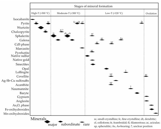
Figure 12.
A paragenetuc sequence of mineral formation in Zn-rich smoker chimneys of the Irinovskoe HSF.
5.1.1. High-Temperature Stage
The presence of this stage at the beginning of the formation of Zn-rich chimneys is indicated by relict isocubanite crystals in the central parts of some chimneys, which are overgrown and replaced by wurtzite. The early isocubanite/wurtzite assemblage points to the starting formation temperature of ~350 °C [44]. This is in accordance with the measured temperatures of 365 °C at two venting sites of the Irinovskoe HSF (see Section 2).
5.1.2. Moderate-Temperature Stage
The outward chimney growth providing a temperature gradient due to conductive cooling is favorable for the crystallization of sphalerite at temperatures of <300 °C [44]. Various morphological types of sphalerite reflect the varying conditions of its formation. The dendritic aggregates are similar to those, e.g., from the Zn-rich samples of the Pipe Organ and Table vent sites, Juan-de-Fuca Ridge, Pacific Ocean, which formed upon quench crystallization at 261 °C [52]. The chaotic orientation of sphalerite domains within the crystalline aggregates (Figure S3-1d) indicates the random growth of crystals when the nucleation rate was greater than the growth rate [54].
The finding of framboidal sphalerite is noteworthy since it is rare in nature in contrast to the abundant pyrite framboids. Framboidal sphalerite was found below the base of the supergene oxidation zone in the Carlin-type Mike gold deposit, Nevada [55], and in the massive sulfides of the Edmond HSF, Central-Indian Ridge [56]. Polyframboids consisting of pyrite and sphalerite were detected in the metapelites of the Otago Schist, New Zealand [57]. Various sphalerite globules consisting of nanoscaled (2–5 nm) sphalerite crystals are known from natural biofilms of a flooded tunnel within carbonate rocks that host the Piquette Pb-Zn deposit, United States [58], and from the polymeric resinous material of Lake Kivu, East Africa [59]. In all cases, except for the Edmond HSF, the formation of sphalerite framboids/globules is attributed to bacterially mediated precipitation.
In spite of the presence of various filamentous structures and relict tube worms in the Zn-rich chimneys of the Irinovskoe HSF, no arguments exist in favor of the biogenically mediated crystallization of sphalerite framboids. Their scarcity most likely indicates an abiotic formation similar to that of pyrite framboids, e.g., due to rapid nucleation in the environments, where the fluid is strongly supersaturated with respect to a particular mineral [60,61] (sphalerite in this case). It was shown that oversaturation and precipitation of sphalerite may occur in the hydrothermal fluid only as it cools to ≤150 °C entering the ambient seawater [62]. The possible local nanoparticulate (actually, colloidal-sized) state of ZnS in the hydrothermal fluid is also very plausible: ZnS nanoparticles were identified in the hydrothermal vents from eastern Lau spreading center, Pacific Ocean [62]. The colloidal-sized particles can also survive in high-temperature (250–352 °C) hydrothermal fluids, which is documented, for example, in the Niua South HSF, Lau Basin, with boiling-induced colloidal-sized (<50 nm to 2 μm) native gold [63].
FeS Content of Zn Sulfides
The FeS content of Zn sulfides (at least, sphalerite) is considered indicative of their formation conditions [64]: the relatively high/low FeS contents are a result of relatively low/high S activity and/or high/low temperatures, respectively. The strongly variable FeS content of Zn sulfides from the Irinovskoe HSF (0.73–17.07 mol%, Table 2 and Table S2-1) points to disequilibrium and nonbuffered precipitation under strongly fluctuating physicochemical conditions [65].
The higher (10.09–15.77 mol %) FeS content of the inner zones and much lower FeS content of the outer zones (2.66–6.76 mol %) of wurtzite crystals (Table 2) indicate an increasing S activity and/or decreasing temperature [7,64,66] as the wurtzite crystals grow. This is generally consistent with a higher-to-lower temperature crystallization trend in smoker chimneys [44]. The zoned reniform sphalerite, however, is characterized by a less pronounced opposite FeS zonation with lower and higher FeS contents in the core and the rims, respectively (Table 2).
Framboidal sphalerite exhibit decreasing center-to-margin FeS contents similar to wurtzite (Table 2) or slightly increasing center-to-margin FeS contents similar to the reniform sphalerite (Table S1). The FeS content of adjacent framboids and microcrystals ranges from 1.74 to 17.07 mol % (Table 2) and this strong difference is achieved at a distance of only 25 µm (Figure 4d, SEM/EDS points d and e). These facts can hardly be explained by highly variable activities of chemical elements and temperature on a micrometer scale. The most plausible explanation is related to the microcrystalline structure of framboids with colloidal-sized microcrystals at the beginning, their larger surface area, the fast growth rate (similar to pyrite framboids [61,67]) and, therefore, an uneven uptake of trace elements. It is known, for example, that pyrite framboids are often characterized by a highly variable trace element composition [30,68,69,70,71], which can be due to over-competition for adsorption sites on the growing Fe sulfides [71].
Fe vs. Cd Competition in Zn Sulfides
Sphalerite is considered a sink for numerous trace elements [19]. Iron and Cd replace Zn via simple substitution mechanisms Zn2+ ↔ Fe2+ and Zn2+ ↔ Cd2+, respectively, which means negative correlations between elements. The correlation coefficients between chemical elements in Zn sulfides from the Irinovskoe HSF could indicate more complex interrelations. For instance, Zn and Fe in the low-Cd wurtzite have the highest correlation coefficient in contrast to the highest Zn–Cd correlation in the low-Cd reniform sphalerite (as well as low-to-high-Cd acicular and anhedral sphalerite) (Table 3). Among six morphological types of Zn sulfides, the crystalline forms (except for the pseudomorphic acicular sphalerite) “prefer” Fe instead of Cd, whereas the reniform, anhedral and pseudomorphic acicular forms favor Cd (even if the Cd contents are lower than the Fe contents as in the reniform and partly anhedral sphalerite). It can, thus, be speculated that the crystalline sphalerite with high Zn–Fe correlation has an α-ZnS sphalerite-type structure, whereas the reniform, anhedral and pseudomorphic sphalerite has a γ-ZnS NaCl-type structure [72]. The latter can possibly be more favorable for the uptake of Cd due to similarity with a NaCl-type structure of a β-CdS phase (hawleyite) [73].
The reniform sphalerite also contains positively correlated Pb and Ag suggesting their coupled substitution (Table 3). In addition to the Zn–Fe correlation, Fe in reniform sphalerite is also correlated with Ag and Pb. This indicates that part of Fe directly substitutes Zn, whereas another part is involved in Ag + Pb substitution probably of the following type: 3Zn2+ ↔ Ag+ + Pb+ + 2Fe2+. Similar “assistance” of Fe in substitution of other trace elements (e.g., Ge) was suggested for sphalerite from the Tres Marias Zn–Pb deposit, Mexico [19].
5.1.3. Low-Temperature Stage
An upper-temperature boundary of 120 °C for this stage is set by the instability of a solid form of native sulfur above 120 °C [74]. This stage was characterized by a reduced activity of S and an enhanced activity of other easily volatilized elements (Cd, Sb, As, Se), leading to the formation of S-deficient mineral assemlages including pyrrhotite, Cd-bearing sphalerite, CdS phase, As-bearing galena, acanthite, naumannite, lollingite, Ag–Sb–Cd-bearing covellite and various Ag–Sb–Cu sulfosalts (Figure 12). The presence of Ag–Sb–Cu sulfosalts, acanthite, Ag-rich native gold, naumannite, baryte, Al-rich opal, native sulfur and mixed-layered kaolinite–smectite phase exhibit certain similarities both with continental and oceanic epithermal-style mineralization (e.g., [6,7,8,75,76]).
Native Sulfur
Although the presence of native sulfur in seafloor environments is ordinary, its known findings (or description) in the MAR HSFs are limited. Native sulfur is reported from the Snake Pit HSF, where it replaces pyrrhotite [2,77], the Azhadze-1 HSF, where it occurs between sphalerite crystals [78], the interior of the TAG mound [79], the Rainbow HSF [3] and hydrothermal precipitates of the Three Sisters volcanic complex in the Bransfield Strait, South Atlantic [7].
In all the above cases, native sulfur forms mainly massive aggregates and its formation is related to oxidation processes. In the Zn-rich chimneys of the Irinovskoe HSF, the native sulfur crystals exhibit acicular morphology as those deposited in open spaces from fumarolic volcanic gases (e.g., [74,80]). In the chimneys studied, native sulfur is hypogene formed prior to a number of minerals, including pseudomorphic acicular pyrrhotite and associated relatively Fe-rich (9–15 mol % FeS) Cd-bearing sphalerite. A possible genetic significance of native sulfur is also considered in Section 5.2.
Cd-Bearing Minerals
The Cd contents of sphalerite from most seafloor HSFs do not generally exceed 1 wt% [7,10,66,81,82,83,84,85,86,87,88,89,90]. Relatively higher Cd contents (>1 wt%) are detected in sphalerite from massive sulfides of the island-arc Palinuro Volcano, Tyrrhenian Sea (up to 1.44 wt%) [8], E-MORB-associated Menez Gwen HSF, MAR (up to 1.73 wt%) [91], basalt-hosted Mt. Jourdanne, Southwest Indian Ridge (up to 1.48 wt%) [92], basalt-hosted MESO HSF, Central Indian Ocean (up to 1.3 wt%) [93] and basalt–andesite-hosted Tinakula HSF, New Hebrids back arc, Pacific Ocean (up to 2.04 wt%) [94]. The highest Cd content (up to 14.04 wt%) in seafloor sphalerite to date is known from the hot-spot-related Loihi volcano, Hawaii [95]. In continental settings, the least Cd content of sphalerite is typical of volcanic-hosted massive sulfide (VHMS) deposits, whereas Mississippi-valley-type (MVT) deposits exhibit a high Cd content of ores and contain Cd-rich sphalerite [19,20,96,97]. In the Uralian VHMS deposits, for example, the Cd content of sphalerite from paleosmoker chimneys increases twice in a range from mafic- to felsic-hosted deposits (from 0.22 to 0.44 ppm Cd, on average, respectively) [71,98].
The extremely high Cd content of sphalerite from the Irinovskoe HSF (up to 41.38 wt%, Table 2) and the finding of the CdS phase are undoubtable evidence that the hydrothermal fluid locally achieved saturation with respect to Cd-bearing minerals. There is a question, however: is this saturation related to the primary enrichment (and why), is it a result of specific formation conditions or is it a combination of both?
The average Cd content of bulk sulfide samples of Zn-rich chimneys studied (445 ppm, Table 8) is lower, for example, than that of Zn-rich chimneys of the TAG active mound (1652 ppm Cd) (our calculations are based on Table 3 from [44]), Logatchev-2 (700 ppm Cd) [3] or Semenov-2 (584 ppm Cd) [10] MAR HSFs. No Cd sulfides, however, have been reported yet from these HSFs, and the highest Cd content of their sphalerite is <1 wt%. The discrepancy between geochemistry and mineralogy could mean that the Irinovskoe HSF provided more favorable conditions for the precipitation of Cd-bearing minerals.
In sedimentary geology, Cd is known as one of the redox-sensitive elements in addition to V, U, Mo, Re, Cr, Ni and Zn [99,100,101]. It is considered that the Cd species are efficiently remobilized under reducing conditions [102]. In the case of the Irinovskoe HSF, the reducing conditions are indicated by the presence of pyrrhotite associated with the Cd-richest sphalerite and a CdS phase. This is also consistent with the results of our physicochemical modeling, which showed the enhanced precipitation of greenockite during the addition of H2 or H2S to the fluid. Acid conditions are also favorable for the enrichment of sphalerite in Cd [96] and are also required, for example, for the formation of a CdS phase (in particular, hawleyite) [74,103].
It was recently found that the concentrations of Ag, Cd, Cu and Co in sphalerite appear to be independent of temperature and the concentrations of, at least, Cd and Co must be controlled by other factors, such as source rock, aquifer, pH, Eh or S fugacity [20]. Nonetheless, there is a general trend between the fluid temperature and the Cd/Zn ratio of the fluids: the higher-temperature exhalative fluids have a low Cd/Zn ratio, the intermediate-temperature geothermal fluids have an intermediate Cd/Zn ratio and the lower-temperature basinal brines have a high Cd/Zn ratio [96]. Even under high-temperature conditions of volcanic fumaroles of Kudryavy Volcano, Kamchatka, the Cd-rich sulfides precipitate at lower temperatures (400 °C) than Zn sulfides (up to 725 °C) [104]. The low-temperature conditions necessary for the increasing Cd contents of sphalerite from paleosmoker chimneys were suggested for the Yaman-Kasy VHMS deposit (South Urals), which contains greenockite [105]. The possibility of low-temperature (<100 °C) crystallization of sphalerite was shown on example of mud volcanoes of Sakhalin Island, Russia [106].
Due to extremely small sizes of the mineral grains, it is impossible to strictly define whether our CdS phase is greenockite (a hexagonal α-form of CdS of the wurtzite group) or hawleyite (a cubic β-form of the sphalerite group). However, on the basis of the Kikuchi patterns of the Cd-rich Zn sulfide, which entirely match sphalerite (a cubic phase) (Figure S3-3), and a continuous series of chemical composition between Zn and Cd sulfides (Figure 13), we speculate that our CdS phase is most likely a cubic hawleyite rather than a hexagonal greenockite. The suggested occurrence of hawleyite, which is considered metastable under all conditions, indicates its non-equilibrium formation conditions [107].
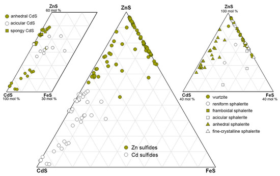
Figure 13.
Compositional ranges of Zn and Cd sulfides from Zn-rich smoker chimneys of the Irinovskoe HSF.
As-Bearing Minerals
Arsenic in Zn-rich chimneys of the Irinovskoe HSF is hosted in galena, Ag–Sb–Cu-sulfosalts (SEM data) and Fe-oxyhydroxides (LA-ICP-MS data [108]). Arsenic is considered an atypical trace element of galena and is thought to be a result of inclusions of tetrahedrite, tennantite or arsenopyrite [109]. Later, however, it was shown that As3+ can be substituted into galena together with Ag+ [110]. Minor amounts of As are detected, for example, in galena from the Santa Eulalia mining district, northern Mexico (0.1–0.7 wt% As) [111], and the hydrothermal precipitates of the Bransfield Strait (max 0.12 wt%) [7], Conical Seamount (max 0.10 wt%) [6], and the Palinuro Volcano (max 1.50 wt%) [8]. Up to 2.25 wt% As in galena from massive sulfides of Mount Jourdanne, Southwest Indian Ridge, are attributed to the microinclusions of other minerals [92]. In contrast, 0.17 wt% As (on average, EMPA data) and 9.34 wt% As (LA-ICP-MS data) in galena from massive sulfides from the Deyin HSF, southern MAR, are interpreted as a substitution of Pb2+ by As3+ at high temperature in the absence of Bi [112].
In our case, the isomorphic Pb–As substitution is supported by: (i) The presence of early As-free galena with an ideal stoichiometric composition (Table S2-3); (ii) The absence of other elements in the chemical composition of As-bearing galena, which could support the occurrence of the inclusions of arsenopyrite/lollingite (Fe) or sulfosalts (Cu, Ag or Sb); (iii) The negative Pb–As correlation (r = –0.99). The “very high” temperatures without specific values necessary for the Pb–As substitution [113] remain enigmatic and the finding of As-bearing galena in Zn-rich chimneys from the Irinovskoe HSF indicates that this substitution could occur at relatively moderate-to-low temperatures of the formation of seafloor galena (<250 °C) [114], or even lower as in our case. According to [115], Y. Moëlo described Sb- and As-bearing galena, the formation of which was related to a high rate of crystallization at low temperature by the substitution in three-fold coordination for Pb. The possibility of As–Pb isomorphic substitution at very low (subsurface) temperatures is also supported by the finding of secondary As-bearing galena (0.08–1.63 wt% As) with a negative Pb–As correlation in a supergene profile of the Dzhusa VHMS deposit (South Urals) [116].
Lollingite is also a rare seafloor mineral that is known from the massive sulfides of the sediment-covered Escanaba Trough, Pacific Ocean [117]. The minerals of the lollingite–safflorite series are mentioned without description at the OCC-related Logatchev-2 HSF, MAR [11]. In the hydrothermal precipitates of the Escanaba Trough, lollingite is associated with pyrrhotite and arsenopyrite, which are indicative of low S and O activity and highly reducing conditions [44,87,117]. The formation of lollingite in our case also supports reducing conditions and indicates even lower S activity, which was insufficient to form arsenopyrite. In continental settings, lollingite is a typical mineral of hydrothermal Co–Ni deposits, e.g., Bou-Azzer in Morocco [118]. According to thermometric studies of fluid inclusions in associated gangue minerals, the arsenide mineralization at this type of deposit forms at relatively low temperatures of <300 °C (mostly, 190–225 °C) [119]. A much lower formation temperature of arsenides (90–110 °C), similar to our interpretations, were reported for the Atrevida Ba-F base metal vein located in the Catalonian coastal ranges of Spain [120].
Ag–Sb-Rich Sulfosalts
Although Sb-bearing sulfosalts are known from seafloor/subseafloor specimens worldwide, they typically contain Pb, As and often Hg [4,6,7,8]. Among the Ag–Sb±Cu sulfosalts from Zn-rich chimneys of the Irinovskoe HSF, only argentotetrahedrite-Zn is one of the relatively abundant seafloor sulfosalts, whereas those close to the compositions of miargyrite, pyrargyrite and stephanite are extremely rare. Similar Ag–Sb sulfosalts are known to date only from opal–baryte samples of the Franklin Seamount (Woodlark spreading basin) (members of the proustite–pyrargyrite isomorphic series) and Manus back-arc basin (miargyrite, pyrargyrite, Fe-freibergite and a mineral of the Ag4(Sb,As)2S5 composition), Pacific Ocean [121,122].
The formation of Ag–Sb±Cu sulfosalts at low temperatures is supported by the stability temperatures of stephanite (<197 °C) [123] and associated acanthite (<173 °C) [124] and their formation after native sulfur (<120 °C) (see above). Our estimations are in line with a suggested temperature range of ~85–100 °C of the formation of, for example, late Sb-bearing mineralization in the Conical Seamount, New Ireland fore-arc [6], and a general “affinity” of Ag and Sb to low-temperature conditions [44,125]. The non-stoichiometric compositions of Ag–Sb±Cu sulfosalts found in the Zn-rich chimneys of the Irinovskoe HSF can indicate the highly unstable local formation conditions.
In the MAR seafloor HSFs, sulfosalts are rare and are dominated by As-rich species. The most abundant tennantite was found in six HSFs in contrast to one HSF with tetrahedrite [3]. The other As- and Sb-bearing sulfosalts were exclusively detected in the OCC-associated HSFs (see Introduction) [11,14,15]. The Semenov-2 and Ashadze-1 HSFs also contain rare Sb-bearing minerals: aurostibite and stibnite, respectively. The findings of Sb minerals exclusively within the OCC-associated structures suggest a possible genetic link between them, which is discussed below.
Naumannite
The presence of naumannite indicates the changes of reducing to oxidizing conditions under low S activity [126]; therefore, it is not ruled out that naumannite formed during the seafloor oxidation stage together with Fe-oxyhydroxides similar to the continental oxidation zones of some VHMS deposits [126]. The rarity of naumannite is in line with the fact that even the lower Se activity relative to the S activity, which is required to form appropriate sulfides, could lead to the formation of selenides at low temperatures [126].
5.1.4. Seafloor Oxidation Stage
All seafloor-exposed massive sulfides are subject to oxidation, which mainly results in the formation of Fe- and Mn-oxyhydroxides after primary hydrothermal minerals [2,9,10,11,12,13,14,15,16,31,44,52]. The chemical composition of Fe- and Mn-oxyhydroxides in the Zn-rich chimneys of the Irinovskoe HSF depends on the replaced mineral, the position in the chimney and the presence of Mn. The Fe-oxyhydroxides from the interior parts of the chimneys, which replace opal or sphalerite, are rich in SiO2 and ZnO, respectively. On the contrary, Fe-oxyhydroxides from the outermost crusts of the chimneys are Mn-bearing reflecting an extensive involvement of seawater in their formation. Manganese is accompanied by a number of elements (V, Co, Ni, Pb, Ti and K) in contrast to Mn-free (as well as V-, Co-, Ni-, Ti-, K- and, locally, Pb-free) Fe-oxyhydroxides, which indicates more successful scavenging of trace elements from seawater in the presence of Mn. This fact can be explained by distinct surface charges of Fe-oxyhydroxide and Mn-oxide colloidal particles similar to deep-sea polymetallic nodules, where negatively charged δ-MnO2 particles attract cations (such as Ni2+ and Co2+) and slightly positively charged FeOOH attract anions [127].
The presence of a water-soluble As2O3 phase, which replaces the As-bearing galena could be the result of laboratory oxidation of samples. On the other hand, claudetite (a monoclinic form of As2O3) was reported from submarine Fe-oxyhydroxide deposits of the Tutum Bay, Papua New Guinea [128], where As is retained in the Fe(III) oxyhydroxides because of prevailing oxidizing conditions and high As activity. The additional evidence of seafloor oxidation origin of the As2O3 phase in our cause is supported by the relatively higher As content of the Fe-oxyhydroxides of the Irinovskoe HSF: 461–7142 ppm [108].
The oxidation of Zn-rich samples occurred at relatively low pH, which is evident from the presence of supergene anglesite and jarosite both requiring acid to neutral conditions for their formation [129,130,131]. The possible occurrence of ultramicroscopic jarosite grains within the Fe- and Mn-oxyhydroxides is suggested from a high positive correlation between K2O and SO3 (r = 0.95) in the composition of Fe- and Mn-oxyhydroxides.
5.2. Matter Sources
Three main sources of major and trace elements in massive sulfides could be involved in the formation of seafloor HSFs: (i) Host rocks usually responsible for providing the main mass of base metals; (ii) Seawater, which supplies, for example, U or V; (iii) A magmatic reservoir, which could yield Au, Bi, Cu, and some other metals (e.g., [3,9,44,132,133,134,135,136]). The metal sources at the OCC-hosted MAR segments could, significantly, be diversified because of diverse host rocks including mafic, ultramafic and felsic (e.g., plagiogranites, diorites and tonalites) types, which are involved in an operating hydrothermal system [3,22,93,137,138]. Our mineralogical–geochemical results indicate that all the sources could make their contribution to the formation of the mineralization at the Irinovskoe HSF under a leading control of mafic rocks that are responsible for the supply of most metals and subordinate roles of ultramafic rocks that provide, possibly, an enrichment in selected trace elements, and a magmatic reservoir that locally induces specific formation conditions.
5.2.1. Possible Mafic/Ultramafic-Related Signatures
According to [3], the Cd/Zn ratio of the MAR massive sulfides can be informative for a possible link with host rock types. The average Cd/Zn ratio of the mafic-related massive sulfides is twice as high (0.0042 at a range of 0.013–0.006) than that of the ultramafic-related massive sulfides (0.0021 at a range of 0.0007–0.0027) (our calculations are based on the data of Table 4 in [3] and Table 2 in [10]). This is in agreement with the difference in Cd concentration between MORBs (0.129 ppm) and ultramafic rocks (0.026 ppm), while the Zn concentration is similar (74 ppm in N-MORBs and 60 ppm in ultramafic rocks) [3]. The average Cd/Zn ratio (0.009) of Zn-rich massive sulfides of the Irinovskoe HSF is the highest among other MAR HSFs, most likely indicating a non-ultramafic source for Cd. Note that the highest Cd/Zn ratio among the MAR mafic-related massive sulfides is determined for those from the E-MORB-associated Menez Gwen and Lucky Strike HSFs (0.006 and 0.005, respectively) (our calculations are based on the data of Table 4 in [3]).
The main role of a mafic rock source is also supported by the high SiO2 content of massive sulfides from the Irinovskoe HSF (27.47–44.89 wt%; an unpublished report of PMGE, 2011) since the quantities of SiO2 in mafic- and ultramafic-related massive sulfides differ more than twice: 12.57 vs. 4.37 wt%, on average (calculated from the data of Table 4 in [3]). The main contribution of mafic rocks is also indicated by the presence of Al-rich opal/Al-bearing clay mineral and jarosite, which require a source for Al and K, respectively. It is noteworthy that jarosite in the MAR has been reported only from mafic-related HSFs (Lucky Strike, TAG, Snake Pit, Broken Spur and Peterburgskoe) [3,13,139] and mafic-controlled OCC-related Semenov-1 and Semenov-3 HSFs [31,140].
Some ultramafic-related signatures can be suggested from the As and Sb contents. The average Sb/As ratio of bulk sulfide samples from the MAR mafic- and OCC-related HSFs is 0.15 and 0.31, respectively (our calculations are based on the data of Table 4 (excluding one anomalous sample from the TAG HSF with a high Sb content of 229 ppm) from [3] + As and Sb contents of the OCC-associated Semenov-2 HSF [10]). These values indicate that mafic-related massive sulfides are relatively richer in As, whereas those from ultramafic/mafic-related systems have higher Sb contents at similar average As contents. The end-member hydrothermal fluids in mafic-dominated systems, however, contain the higher contents both of As and Sb (Table 2 in [3]). This “contradiction” means that the formation conditions provided by ultramafic-bearing systems could be more favorable for the crystallization of Sb minerals even at the lower Sb contents of the hydrothermal fluids.
It was shown that boiling and vapor-brine separation may exert an important control on Sb transport and distribution [141]. Antimony chloride and hydroxychloride species are expected to preferentially partition into the vapor phase. In contrast, As does not exhibit significant changes in its vapor–liquid fractionation patterns in the H2O–NaCl–HCl system as a function of HCl [142]. It, thus, can be speculated that the formation of Sb minerals in the OCC-related seafloor environments can indirectly mirror the phase separation events, which are observed in situ and documented from fluid inclusion studies at the Logatchev, Ashadze, Rainbow, Semenov-1 and Semenov-2 OCC-associated HSFs [10,31,143,144,145].
It is well known that the Sb-bearing sulfosalts often occur in the HSFs, which are associated with felsic volcanic rocks (e.g., [4,6,7,8,121,146]). Thus, we cannot also exclude a link between Sb mineralization in the OCC-related HSFs and their felsic host rock components similar to a suggested hydrothermal leaching of felsic rock that differentiates underneath the basaltic cover and the subsequent zone refining processes, which are invoked to explain the polymetallic enrichment of massive sulfides from Mount Jourdanne basaltic volcano along the slow-spreading Southwest Indian Ridge [92].
5.2.2. Possible Magmatic-Related Signatures
Magmatic-related signatures could be supported by the presence of primary acicular native sulfur crystals and the negative S isotopic composition of bulk sulfide samples. The formation of native sulfur in seafloor environments can be related to the oxidation of excess H2S [7,133] or pyrrhotite (or sulfides) [3], or reflects disproportionation reactions involving magmatic SO2 [9,136,147]. We do not exclude both scenarios because the native sulfur crystals are locally associated with subhedral pyrite crystals (Figure S1-51); however, the oxidation of sulfides cannot account for the negative S isotopic composition of bulk sulfide samples (Table 10). The S isotopic composition of sulfides can also be shifted to the negative values by bacterial-sulfate reduction or boiling [147], but the link between these processes and the precipitation of native sulfur is obscure. If the disproportionation reaction between magma-derived SO2 and the fluid occurred in our case occurs, it yields acidic conditions favorable for the formation of native sulfur [148]. Acidic conditions were also favorable for further formation of Al-bearing opal (up to 10 wt% Al2O3) around native sulfur aggregates. It is known that Al is effectively leached from silicate minerals by acid attacks [148, 149 and references therein]. The acidic conditions are also consistent with the presence of Al-bearing phyllosilicates represented by a mixed-layered kaolinite–smectite phase [6,148,149].
5.2.3. Constraints from Physicochemical Modeling
The physicochemical calculations of the R/SW interaction showed that the formation of a Cd sulfide (greenockite in modeling) in Zn-rich smoker chimneys is possible in both (basalt- and peridotite-related) systems during the penetration of a hydrothermal fluid through the porous wall of the chimney upon decreasing temperature. The amount of CdS phase directly depends on the Cd content in the parental rock, so the Cd source is also important. The involvement of magmatic gas enhances the Cd content in the fluid and, thus, the chances of crystallization of Cd-bearing sphalerite and Cd sulfide. The modeling crystallization of miargyrite and pyrargyrite in the peridotite-related system indirectly supports a possible genetic link between Sb and ultramafic rocks.
5.3. Potential Ecological Risks
It is known that on-land open-pit mining of sulfide deposits generates large amounts of sulfide-bearing wastes, including waste rock, mill tailings and low-grade ores ([150] and references therein). Among other sulfides, sphalerite undergoes fast weathering causing elevated concentrations of Zn and trace elements (including Cd) in mine drainage. The weathering of sphalerite is a complex process because of the dissimilar weathering behaviors of ferroan and Fe-poor sphalerite and wurtzite, the differential sorption of Cd and Zn by tailings and the formation and dissolution of Cd- and Zn-bearing soluble sulfate minerals of which the Cd-bearing forms are more soluble [151].
In seafloor conditions, however, the weathering process occurs in chemically buffered waters of near neutral pH, resulting in the formation of insoluble Fe oxyhydroxides [152]. As a result, it is assumed that seafloor massive sulfides are unlikely to exhibit a significant loss of metals (dissolution and release of heavy metals) into the water column.
The situation can change upon the possible mining of seafloor sulfides, which would require their delivery on a vessel to more aggressive oxygenated conditions. The potential ecological risks in case of possible seafloor mining, however, are still unclear. They will depend on many factors, including, first, mineralogical–geochemical features of seafloor massive sulfides (the mode of occurrence of, for example, Cd as a trace element in sulfides or as Cd minerals) and, second, their processing procedure on seafloor (the degree of fragmentation of the sulfide material, which increases the particle sizes) and on the vessel (storage of sulfide material, its drying conditions, etc.). As shown in the current paper, the necessity of the detailed mineralogical studies of seafloor massive sulfides is crucially important. The deportment of Cd is still unclear in some HSFs with high Cd contents of bulk massive sulfides and relatively low (<1 wt%) Cd contents of sphalerite (e.g., Semenov-2 HSF [10]).
6. Conclusions
The extinct Zn-rich smoker chimneys of the OCC-related Irinovskoe hydrothermal sulfide field in the Mid-Atlantic Ridge formed due to the lower flow velocity of relatively lower temperature fluids and the restricted mixing of fluid and seawater. The mineralogical–geochemical features of the chimneys indicate the abundance of specific local formation conditions, which led to the precipitation of various morphological types of Zn sulfides from euhedral/subhedral crystals to anhedral, reniform, framboidal and acicular aggregates. The high Cd content of sphalerite, reaching up to 41.38 wt%, and the presence of a CdS phase (most likely, hawleyite) are the most remarkable features of Zn-rich chimneys.
The formation of chimneys started at a high temperature (>350 °C) as supported by the occurrence of isocubanite and wurtzite crystals in the central parts of the chimneys. The decrease in temperature of the hydrothermal fluid (<<300 °C) and the outward chimney growth providing a temperature gradient were favorable for further crystallization of sphalerite. The sphalerite framboids locally crystallized from rapidly nucleating colloidal-size particles. The strongly variable FeS content of all Zn sulfides points to disequilibrium and nonbuffered precipitation under strongly fluctuating physicochemical conditions. The strongly variable FeS content of sphalerite framboids is explained by their microcrystalline structure with a larger surface area, their fast growth rate and an uneven uptake of trace elements. The different morphological types of sphalerite are characterized by different isomorphic substitutions of Zn. The crystalline forms (except for the acicular sphalerite pseudomorphic after native sulfur) “prefer” Fe instead of Cd showing a high negative Fe–Zn correlation probably because of their α-ZnS sphalerite-type structure. The reniform, anhedral and pseudomorphic acicular forms with high negative Cd–Zn correlation favor Cd due to their possible γ-ZnS NaCl-type structure, which is similar to a NaCl-type structure of β-CdS phase (hawleyite).
The low-temperature stage of formation of Zn-rich chimneys yielded most accessory minerals, including native sulfur, pyrrhotite, Cd-rich sphalerite, CdS phase (most likely, hawleyite), Ag–Cu–Sb(±As) sulfosalts with compositions close to miargyrite, pyrargyrite, stephanite and argentotetrahedrite-Zn, As-bearing galena, acanthite, Ag-, Sb-, and Cd-rich covellite, Ag-rich native gold, a mixed-layered kaolinite–smectite phase, opal and its Al-rich variety, lollingite and naumannite. Some minerals of this stage resemble those from both continental and oceanic epithermal deposits. Their crystallization could be initiated by a magmatic input, which is suggested by the presence of hypogene acicular native sulfur and negative S isotopic composition of bulk sulfide samples. The presence of native sulfur, Al-rich opal and mixed-layered kaolinite–smectite phase also points to acidic formation conditions. The presence of pyrrhotite, lollingite and As-bearing galena indicates low S activity and increasing As activity. The occurrence of Sb minerals, exclusively within the OCC-related hydrothermal sulfide fields of the Mid-Atlantic Ridge, reflects a possible genetic link to these geological settings and could be a new proxy for the OCC-related massive sulfides. Our mineralogical–geochemical results indicate that most metals for the Zn-rich sulfides of the Irinovskoe hydrothermal sulfide field were sourced from mafic rocks, with a subordinate role of ultramafic rocks, which were responsible for enrichment in selected trace elements (Sb?), and a magmatic reservoir, which provided local specific formation conditions.
The finding of the Cd-rich sphalerite and CdS phase in low-temperature mineral assemblage significantly expands the temperature boundaries for the possible formation of Cd sulfides. The high Cd contents of easily soluble sphalerite and the presence of the CdS phase should be taken into account in possible future mining seafloor hydrothermal sulfide fields and further processing of their sulfides.
Supplementary Materials
The following materials are available online at https://www.mdpi.com/article/10.3390/min12121626/s1, Figure S1: Morphology of minerals from Zn-rich chimneys of the Irinovskoe HSF, BSE images; Figure S2: Results of EBSD studies; Figure S3: Plots of Eh, pH (a, a’), molality of elements in solution (b, b’) and contents of secondary minerals (c–e, c’–e’), which form during basalt/seawater (a–e) and serpentinized peridotite/seawater (a’–e’) interaction at a temperature of 350 °C and a pressure of water column of ~50 MPa (~5500 m) depending on the basalt/seawater ratio. Table S1: Chemical composition of Zn sulfides, wt%; Table S2: Correlation coefficients between chemical elements in various Zn and Cd sulfides of the Irinovskoe HSF; Table S3: Chemical composition of Cd sulfides of the Irinovskoe HSF, wt%; Table S4: Chemical composition of chalcopyrite, isocubanite, covellite and galena of the Irinovskoe HSF, wt%; Table S5: Chemical composition of non-stoichiometric Ag–Sb–Cu minerals of the Irinovskoe HSF, wt%; Table S6: Chemical composition of Fe- and Mn-oxyhydroxides of the Irinovskoe HSF, wt%; Table S7: Chemical composition of baryte and anglesite of the Irinovskoe HSF, wt%; Table S8: Analytical uncertainties for AAA-based contents of chemical elements of chimney samples from the Irinovskoe HSF, ppm; Table S9: Analytical uncertainties for ICP-MS-based contents of chemical elements of chimney samples from the Irinovskoe HSF, ppm.
Author Contributions
Sampling, conceptualization, mineralogical studies, original draft preparation, review and editing, I.M.; SEM studies, V.K.; thermodynamic modeling and editing, G.T.; EBSD studies and editing, V.S. and E.B.; XRD studies, P.K.; geological studies and sampling, V.B.; ICP-MS analysis, K.F.; S isotopic analysis, S.S. All authors have read and agreed to the published version of the manuscript.
Funding
This research was funded by State Contract of the South Urals Federal Research Center of Mineralogy and Geoecology UB RAS no. 122031600292-6 and partly by a project SID2022 “Critical and precious metals on mid-ocean ridges and in ophiolites: where and how?” (University of Padova, Padova, Italy).
Data Availability Statement
Not applicable.
Acknowledgments
The authors sincerely acknowledge the administration of the PGME for the possibility of participation in the 34th cruise of R/V Logatchev and sampling the massive sulfide samples, Marina Malyarenok, Tamara Semenova, Yuliya Melnova and Maria Svirenko for titrimetric and AAA analyses, Nuriya Ayupova for fruitful discussion of results, the two anonymous reviewers and the academic editor for their valuable remarks allowing the improvement of the manuscript.
Conflicts of Interest
The authors declare no conflict of interest.
References
- Fouquet, Y.; Henry, K.; Knott, R.; Cambon, P. Geochemical section of the TAG hydrothermal mound. In Proceedings of the Ocean Drilling Program, Scientific Results; Herzig, P.M., Humphris, S.E., Miller, D.J., Zierenberg, R.A., Eds.; Elsevier: Amsterdam, The Netherlands, 1998; Volume 158, pp. 363–387. [Google Scholar]
- Fouquet, Y.; Wafik, A.; Cambon, P.; Mevel, C.; Meyer, G.; Gente, P. Tectonic setting and mineralogical and geochemical zonation in the Snake Pit sulfide deposit (Mid-Atlantic Ridge at 23° N). Econ. Geol. 1993, 88, 2018–2036. [Google Scholar] [CrossRef]
- Fouquet, Y.; Cambon, P.; Etoubleau, J.; Charlou, J.-L.; Ondréas, H.; Barriga, F.J.A.S.; Cherkashov, G.; Semkova, T.; Poroshina, I.; Bohn, M.; et al. Geodiversity of hydrothermal processes along the Mid-Atlantic Ridge and ultramafic-hosted mineralization: A new type of oceanic Cu-Zn-Co-Au volcanogenic massive sulfide deposits. In Diversity of Hydrothermal Systems on Slow Spreading Ocean Ridges; Rona, P.A., Devey, C.W., Dyment, J., Murton, B.J., Eds.; AGU Geophys. Monograph; Wiley-Blackwell: Hoboken, NJ, USA, 2010; pp. 321–368. [Google Scholar]
- Halbach, P.; Praceius, B.; Marten, A. Geology and mineralogy of massive sulphide ores from the Central Okinawa Trough, Japan. Econ. Geol. 1993, 88, 2210–2225. [Google Scholar] [CrossRef]
- Herzig, P.M.; Hannington, M.D.; Fouquet, Y.; von Stackelberg, U.; Petersen, S. Gold-rich polymetallic sulfides from the Lau back arc and implications for the geochemistry of gold in sea-floor hydrothermal systems of the Southwest Pacific. Econ. Geol. 1993, 88, 2182–2209. [Google Scholar] [CrossRef]
- Petersen, S.; Herzig, P.M.; Hannington, M.D.; Jonasson, I.R.; Arribas, A., Jr. Submarine gold mineralization near Lihir Island, New Ireland fore-arc, Papua New Guinea. Econ. Geol. 2002, 97, 1795–1813. [Google Scholar] [CrossRef]
- Petersen, S.; Herzig, P.M.; Schwarz-Schampera, U.; Hannington, M.D.; Jonasson, I.R. Hydrothermal precipitates associated with bimodal volcanism in the Central Bransfield Strait, Antarctica. Miner. Depos. 2004, 39, 358–379. [Google Scholar] [CrossRef]
- Petersen, S.; Monecke, T.; Westhues, A.; Hannington, M.D.; Gemmell, J.B.; Sharpe, R.; Peters, M.; Strauss, H.; Lackschewitz, K.; Augustin, N.; et al. Drilling shallow-water massive sulfides at the Palinuro volcanic complex, Aeolian island arc, Italy. Econ. Geol. 2014, 109, 2129–2157. [Google Scholar] [CrossRef]
- de Ronde, C.E.J.; Massoth, G.J.; Butterfield, D.A.; Christenson, B.W.; Ishibashi, J.; Ditchburn, R.G.; Hannington, M.D.; Brathwaite, R.L.; Lupton, J.E.; Kamenetsky, V.S.; et al. Submarine hydrothermal activity and gold-rich mineralization at Brothers Volcano, Kermadec Arc, New Zealand. Mineral. Depos. 2011, 46, 541–584. [Google Scholar] [CrossRef]
- Melekestseva, I.Y.; Maslennikov, V.V.; Tret’yakov, G.A.; Nimis, P.; Beltenev, V.E.; Rozhdestvenskaya, I.I.; Maslennikova, S.P.; Belogub, E.V.; Danyushevsky, L.; Large, R.; et al. Gold- and silver-rich massive sulfides from the Semenov-2 hydrothermal field, 13°31.13´ N, Mid-Atlantic Ridge: A case of magmatic contribution? Econ. Geol. 2017, 112, 741–773. [Google Scholar] [CrossRef]
- Lein, A.Y.; Cherkashov, G.A.; Ul’yanov, A.A.; Ul’yanova, N.V.; Stepanova, T.V.; Sagalevich, A.M.; Bogdanov, Y.A.; Gurvich, E.G.; Torokhov, M.P. Mineralogy and geochemistry of sulfide ores from the Logachev-2 and Rainbow fields: Similar and distinctive features. Geokhimiya 2003, 41, 271–294. (In Russian) [Google Scholar]
- Bogdanov, Y.A.; Lein, A.Y.; Sagalevich, A.M.; Dorofeev, S.A.; Ul’yanova, N.V. Hydrothermal sulfide deposits of the Lucky Strike vent field, Mid-Atlantic Ridge. Geochem. Intern. 2006, 44, 403–418. [Google Scholar] [CrossRef]
- Bogdanov, Y.A.; Lein, A.Y.; Maslennikov, V.V.; Li, S.; Ul’yanov, A.A. Mineralogical–geochemical features of sulfide ores from the Broken Spur hydrothermal vent field. Oceanology 2008, 48, 679–700. [Google Scholar] [CrossRef]
- Firstova, A.; Stepanova, T.; Cherkashov, G.; Goncharov, A.; Babaeva, S. Composition and formation of gabbro-peridotite hosted seafloor massive sulfide deposits from the Ashadze-1 hydrothermal field, Mid-Atlantic Ridge. Minerals 2016, 6, 19. [Google Scholar] [CrossRef]
- Firstova, A.; Stepanova, T.; Sukhanova, A.; Cherkashov, G.; Poroshina, I. Au and Te minerals in seafloor massive sulphides from Semyenov-2 hydrothermal field, Mid-Atlantic Ridge. Minerals 2019, 9, 294. [Google Scholar] [CrossRef]
- Hussain, C.M.; Keçili, R. Environmental pollution and environmental analysis. In Modern Environmental Analysis Techniques for Pollutants; Elsevier: Amsterdam, The Netherlands, 2020; pp. 1–36. [Google Scholar]
- Available online: www.mindat.org (accessed on 15 March 2022).
- Kelley, K.D.; Leach, D.L.; Johnson, C.A.; Clark, J.L.; Fayek, M.; Slack, J.F.; Anderson, V.M.; Ayuso, L.E.; Ridley, W.I. Textural, compositional, and sulfur isotope variations of sulfide minerals in the Red Dog Zn–Pb–Ag deposits, Brooks Range, Alaska: Implications for ore formation. Econ. Geol. 2004, 99, 1509–1532. [Google Scholar] [CrossRef]
- Cook, N.J.; Ciobanu, C.L.; Pring, A.; Skinner, W.; Shimizu, M.; Danyushevsky, L.; Saini-Eidukat, B.; Melcher, F. Trace and minor elements in sphalerite: A LA-ICPMS study. Geochim. Cosmochim. Acta 2009, 73, 4761–4791. [Google Scholar] [CrossRef]
- Frenzel, M.; Hirsch, T.; Gutzmer, J. Gallium, germanium, indium, and other trace and minor elements in sphalerite as a function of deposit type—A meta-analysis. Ore Geol. Rev. 2016, 76, 52–78. [Google Scholar] [CrossRef]
- Iizasa, K.; Yuasa, M.; Yokota, S. Mineralogy and geochemistry of volcanogenic sulfides from the Myojinsho submarine caldera, the Shichito-Iwojima Ridge, Izu-Ogasawara Arc, northwestern Pacific. Mar. Geol. 1992, 108, 39–58. [Google Scholar] [CrossRef]
- MacLeod, C.J.; Searle, R.C.; Murton, B.J.; Casey, J.F.; Mallows, C.; Unsworth, S.C.; Achenbach, K.L.; Harris, M. Life cycle of oceanic core complexes. Earth Planet. Sci. Lett. 2009, 287, 333–344. [Google Scholar] [CrossRef]
- Beltenev, V.B.; Ivanov, V.N.; Sergeev, M.B.; Rozhdestvenskaya, I.I.; Samovarov, M.L. Results of prospecting works for base metal sulfides in the Atlantic Ocean in 2011 in the light of submitting the Russian application in ISA. Razved. Okhr. Nedr. 2012, 8, 50–55. (In Russian) [Google Scholar]
- Kuznetsov, V.Y.; Tabuns, E.V.; Cherkashev, G.A.; Bel’tenev, V.E.; Maksimov, F.E.; Kuksa, K.A.; Lazareva, L.I.; Levchenko, S.B.; Zherebtsov, I.E. 230Th/U chronology and geochemistry of Irinovskoe hydrothermal field (Mid-Atlantic Ridge). Dokl. Earth Sci. 2018, 478, 26–30. [Google Scholar] [CrossRef]
- Jamieson, J.W.; Petersen, S.; Augustin, N.; Steinführer, A.; Escartin, J.; ODEMAR Scientific Party. Seafloor massive sulfide formation on oceanic core complexes: Recent exploration of the Semyenov and Irinovskoe hydrothermal fields, Mid-Atlantic Ridge. In Proceedings of the Minerals of the Ocean-7 and Deep-Sea Minerals and Mining-4, Russia, VNIIOkeangeologiya, St-Petersburg, Russia, 5–6 February 2014; pp. 42–45. [Google Scholar]
- Escartín, J.; Mével, C.; Petersen, S.; Bonnemains, D.; Cannat, M.; Andreani, M.; Augustin, N.; Bezos, A.; Chavagnac, V.; Choi, Y.; et al. Tectonic structure, evolution, and the nature of oceanic core complexes and their detachment fault zones (13°20′N and 13°30′N, Mid Atlantic Ridge). Geochem. Geophys. Geosyst. 2017, 18, 1451–1482. [Google Scholar] [CrossRef]
- Lavrent’ev, Y.G.; Karmanov, N.S.; Usova, L.V. Electron probe microanalysis of minerals: Microanalyzer or scanning electron microscope? Rus. Geol. Geophys. 2015, 56, 1154–1161. [Google Scholar] [CrossRef]
- Warr, L.N. IMA–CNMNC approved mineral symbols. Miner. Mag. 2021, 85, 291–320. [Google Scholar] [CrossRef]
- Biagioni, C.; George, L.L.; Cook, N.J.; Makovicky, E.; Moëlo, Y.; Pasero, M.; Sejkora, J.; Stanley, C.J.; Welch, M.D.; Bosi, F. The tetrahedrite group: Nomenclature and classification. Am. Miner. 2020, 105, 109–122. [Google Scholar] [CrossRef]
- Handbook of Mineralogy. Available online: https://handbookofmineralogy.org/pdf-search/ (accessed on 16 April 2022).
- Melekestseva, I.Y.; Tret’yakov, G.A.; Nimis, P.; Yuminov, A.M.; Maslennikov, V.V.; Maslennikova, S.P.; Kotlyarov, V.A.; Beltenev, V.E.; Danyushevsky, L.V.; Large, R. Barite-rich massive sulfides from the Semenov-1 hydrothermal field (Mid-Atlantic Ridge, 13°30.87′ N): Evidence for phase separation and magmatic input. Mar. Geol. 2014, 349, 37–54. [Google Scholar] [CrossRef]
- Toffolo, L.; Nimis, P.; Tret’yakov, G.A.; Melekestseva, I.Y.; Beltenev, V.E. Seafloor massive sulfides from mid-ocean ridges: Exploring the causes of their geochemical variability with multivariate analysis. Earth-Sci. Rev. 2020, 201, 102958. [Google Scholar] [CrossRef]
- Craig, J.R.; Barton, P.B. Thermochemical approximations for sulfosalts. Econ. Geol. 1973, 68, 493–506. [Google Scholar] [CrossRef]
- Sack, R.O. Internally consistent database for sulfides and sulfosalts in the system Ag2S–Cu2S–ZnS–Sb2S3–As2S3. Geochim. Cosmochim. Acta 2000, 64, 3803–3812. [Google Scholar] [CrossRef]
- Seal, R.R., II; Robie, R.A.; Hemingway, B.S.; Evans, H.T., Jr. Heat capacity and entropy at the temperatures 5 K to 720 K and thermal expansion from the temperatures 298 K to 573 K of synthetic enargite (Cu2AsS3). J. Chem. Thermodyn. 1996, 28, 405–412. [Google Scholar] [CrossRef]
- Helgeson, H.C. Evaluation of irreversible reactions in geochemical processes involving minerals and aqueous solutions–I. Thermodynamic relations. Geochim. Cosmochim. Acta 1968, 39, 853–877. [Google Scholar] [CrossRef]
- Karpov, I.K.; Chudnenko, K.V.; Kulik, D.A. Modeling chemical mass transfer in geochemical processes: Thermodynamic relations, conditions of equilibrium, and numerical algorithms. Am. J. Sci. 1997, 297, 767–806. [Google Scholar] [CrossRef]
- Chudnenko, K.V. Thermodynamic Modeling in Geochemistry: Theory, Algorithms, Software, and Applications; Geo: Novosibirsk, Russia, 2010; 287p. (In Russian) [Google Scholar]
- Lehnert, K.; Su, Y.; Langmuir, C.; Sarbas, B.; Nohl, U. A global geochemical database structure for rocks. Geochem. Geophys. Geosyst. 2000, 1, 1–14. [Google Scholar] [CrossRef]
- Melson, W.G.; Hart, S.R.; Thompson, G.S. Paul’s Rocks, Equatorial Atlantic: Petrogenesis, Radiometric Ages, and Implications on Sea-Floor Spreading; The Geological Society of America: Boulder, CO, USA, 1972; Memoir 132; pp. 241–272. [Google Scholar]
- Steele, J.H.; Thorpe, S.A.; Turekian, K.K. (Eds.) Encyclopedia of Ocean Sciences, 2nd ed.; Appendix 3. Estimated Mean Oceanic Concentrations of the Elements; Elsevier: Amsterdam, Netherlands, 2010; pp. 602–603. [Google Scholar]
- Zelenski, M.E.; Fischer, T.P.; de Moor, J.M.; Marty, B.; Zimmermann, L.; Ayalew, D.; Nekrasov, A.N.; Karandashev, V.K. Trace elements in the gas emissions from the Erta Ale volcano, Afar, Ethiopia. Chem. Geol. 2013, 357, 95–116. [Google Scholar] [CrossRef]
- Dixon, J.E.; Stolper, E.M. An experimental study of water and carbon dioxide solubilities in mid-ocean ridge basaltic liquids. Part II: Applications to degassing. J. Petrol. 1995, 36, 1633–1646. [Google Scholar]
- Hannington, M.D.; Jonasson, I.R.; Herzig, P.M.; Petersen, S. Physical and chemical processes of seafloor mineralization at mid-ocean ridges. In Seafloor Hydrothermal Processes; Humphris, S.E., Zierenberg, R.A., Mullineaux, L.S., Thomson, R.E., Eds.; Geophysical Monograph 91; American Geophysical Union: Washington, DC, USA, 1995; pp. 115–157. [Google Scholar]
- Bischoff, J.L.; Rosenbauer, R.J. The critical point and two-phase boundary of seawater, 200–500 °C. Earth Planet. Sci. Lett. 1984, 68, 172–180. [Google Scholar] [CrossRef]
- Gruen, G.; Weis, P.; Driesner, T.; Heinrich, C.A.; de Ronde, C.E.J. Hydrodynamic modeling of magmatic–hydrothermal activity at submarine arc volcanoes, with implications for ore formation. Earth Planet. Sci. Lett. 2014, 404, 307–318. [Google Scholar] [CrossRef]
- Janecky, D.R.; Seyfried, W.E., Jr. Hydrothermal serpentinization of peridotite within the oceanic crast: Experimental investigations of mineralogy and major element chemistry. Geochim. Cosmochim. Acta 1986, 50, 1357–1378. [Google Scholar] [CrossRef]
- McCollom, T.M.; Shock, E.L. Fluid-rock interactions in the lower oceanic crust: Thermodynamic models of hydrothermal alteration. J. Geophys. Res. 1998, 103, 547–575. [Google Scholar] [CrossRef]
- Grichuk, D.V. Thermodynamic Models of Submarine Hydrothermal Hydrothermal System; Nauchny Mir: Moscow, Russia, 2000; 303p. (In Russian) [Google Scholar]
- Palandri, J.L.; Reed, M.H. Geochemical models of metasomatism in ultramafic systems: Serpentinization, rodingitization, and sea floor carbonate chimney precipitation. Geochim. Cosmochim. Acta 2004, 68, 1115–1133. [Google Scholar] [CrossRef]
- Pierre, S.; Gysi, A.P.; Monecke, T. Fluid chemistry of mid-ocean ridge hydrothermal vents: A comparison between numerical modeling and vent geochemical data. Geofluids 2018, 2018, 1389379. [Google Scholar] [CrossRef]
- Koski, R.A.; Jonasson, I.R.; Kadko, D.C.; Wong, F.L. Compositions, growth mechanisms, and temporal relations of hydrothermal sulfide-sulfate-silica chimneys at the northern Cleft segment, Juan de Fuca Ridge. J. Geophys. Res. 1994, 99, 4813–4832. [Google Scholar] [CrossRef]
- Hannington, M.D.; de Ronde, C.E.J.; Petersen, S. Sea-floor tectonics and submarine hydrothermal systems. Econ. Geol. 2005, 100, 111–141. [Google Scholar]
- Hu, S.-Y.; Barnes, S.J.; Glenn, A.M.; Pages, A.; Parr, J.; MacRae, C.; Binns, R. Growth history of sphalerite in a modern sea floor hydrothermal chimney revealed by electron backscattered diffraction. Econ. Geol. 2019, 114, 165–176. [Google Scholar] [CrossRef]
- Bawden, T.M.; Einaudi, M.T.; Bostick, B.C.; Meibom, A.; Wooden, J.; Norby, J.W.; Orobona, M.J.T.; Chamberlain, C.P. Extreme 34S depletions in ZnS at the Mike gold deposit, Carlin Trend, Nevada: Evidence for bacteriogenic supergene sphalerite. Geology 2003, 31, 913–916. [Google Scholar] [CrossRef]
- Wu, Z.; Sun, X.; Xu, H.; Konishi, H.; Wang, Y.; Lu, Y.; Cao, K.; Wang, C.; Zhou, H. Microstructural characterization and in-situ sulfur isotopic analysis of silver-bearing sphalerite from the Edmond hydrothermal field, Central Indian Ridge. Ore Geol. Rev. 2018, 92, 318–347. [Google Scholar] [CrossRef]
- Hu, S.-Y.; Evans, K.; Rempel, K.; Guagliardo, P.; Kilburn, M.; Craw, D.; Grice, K.; Dick, J. Sequestration of Zn into mixed pyrite-zinc sulfide framboids: A key to Zn cycling in the ocean? Geochim. Cosmochim. Acta 2018, 241, 95–107. [Google Scholar] [CrossRef]
- Labrenz, M.; Druschel, G.K.; Thomsen-Ebert, T.; Gilbert, B.; Welch, S.A.; Kemner, K.M.; Logan, G.A.; Summons, R.E.; De Stasio, G.; Bond, P.L.; et al. Formation of sphalerite (ZnS) deposits in natural biofilms of sulfate-reducing bacteria. Science 2000, 290, 1744–1747. [Google Scholar] [CrossRef] [PubMed]
- Degens, E.T.; Okada, H.; Honjo, S.; Hathaway, J.C. Microcrystalline sphalerite in resin globules suspended in Lake Kivu, East Africa. Mineral. Depos. 1972, 7, 1–12. [Google Scholar] [CrossRef]
- Farrand, M. Framboidal sulphides precipitated synthetically. Mineral. Depos. 1970, 5, 237–247. [Google Scholar] [CrossRef]
- Butler, I.B.; Rickard, D. Framboidal pyrite formation via the oxidation of iron (II) monosulfide by hydrogen sulphide. Geochim. Cosmochim. Acta 2000, 64, 2665–2672. [Google Scholar] [CrossRef]
- Hsu-Kim, H.; Mullaugh, K.M.; Tsang, J.J.; Yucel, M.; Luther, G.W., III. Formation of Zn- and Fe-sulfides near hydrothermal vents at the Eastern Lau Spreading Center: Implications for sulfide bioavailability to chemoautotrophs. Geochem. Transac. 2008, 9, 6. [Google Scholar] [CrossRef]
- Gartman, A.; Hannington, M.; Jamieson, J.W.; Peterkin, B.; Garbe-Schönberg, D.; Findlay, A.J.; Fuchs, S.; Kwasnitschka, T. Boiling-induced formation of colloidal gold in black smoker hydrothermal fluids. Geology 2018, 46, 39–42. [Google Scholar] [CrossRef]
- Vaughan, D.J.; Craig, J.R. Sulphide ore mineral stabilities, morphologies, and intergrowth textures. In Geochemistry of Hydrothermal Ore Deposits, 3rd ed.; Barnes, H.L., Ed.; John Wiley & Sons: New York, NY, USA, 1997; pp. 367–434. [Google Scholar]
- Duckworth, R.C.; Fallick, A.E.; Rickard, D. Mineralogy and sulfur isotopic composition of the Middle Valley massive sulfide deposit, Northern Juan se Fuca Ridge. In Proceedings of the Ocean Drilling Program, Scientific Results; Mottl, M.J., Davis, E.E., Fisher, A.T., Slack, J.F., Eds.; Texas A & M University: College Station, TX, USA, 1994; Volume 139, pp. 373–385. [Google Scholar]
- Marques, A.F.A.; Barriga, F.J.A.S.; Chavagnac, V.; Fouquet, Y. Mineralogy, geochemistry, and Nd isotope composition of the Rainbow hydrothermal field, Mid-Atlantic Ridge. Miner. Depos. 2006, 41, 52–67. [Google Scholar] [CrossRef]
- Wilkin, R.T.; Barnes, H.L. Formation processes of framboidal pyrite. Geochim. Cosmochim. Acta 1997, 61, 323–339. [Google Scholar] [CrossRef]
- Large, R.R.; Maslennikov, V.V.; Robert, F.; Danyushevsky, L.V. Multistage sedimentary and metamorphic origin of pyrite and gold in the giant Sukhoi Log deposit, Lena gold province, Russia. Econ. Geol. 2007, 102, 1233–1267. [Google Scholar] [CrossRef]
- Safina, N.P.; Maslennikov, V.V. Ore Clastic Sediments from Yaman-Kasy and Saf’yanovka Massive Sulfide Deposits, the Urals; IMin UrO RAN: Miass, Russia, 2009; 260p. (In Russian) [Google Scholar]
- Maslennikov, V.V.; Ayupova, N.R.; Maslennikova, S.P.; Tret’yakov, G.A.; Melekestseva, I.Y.; Safina, N.P.; Belogub, E.V.; Large, R.R.; Danyushevsky, L.V.; Tseluyko, A.S.; et al. Toxic Elements in Massive Sulfide Systems; RIO UrO RAN: Yekaterinburg, Russia, 2014; 340p. (In Russian) [Google Scholar]
- Gregory, D.D.; Meffre, S.; Large, R.R. Comparison of metal enrichment in pyrite framboids from a metal-enriched and metal-poor estuary. Amer. Miner. 2014, 99, 633–644. [Google Scholar] [CrossRef]
- Hotje, U.; Rose, C.; Binnewies, M. Lattice constants and molar volume in the system ZnS, ZnSe, CdS, CdSe. Solid State Sci. 2003, 5, 1259–1262. [Google Scholar] [CrossRef]
- Traill, R.J.; Boyle, R.W. Hawleyite, isometric cadmium sulphide, a new mineral. Amer. Miner. 1955, 40, 555–559. [Google Scholar]
- Balić-Žunić, T.; Garavelli, A.; Jakobsson, S.P.; Jonasson, K.; Katerinopoulos, A.; Kyriakopoulos, K.; Acquafredda, P. Fumarolic minerals: An overview of active European volcanoes. In Updates in Volcanology—From Volcano Modelling to Volcano Geology; Nemeth, K., Ed.; InTech Open Access Publishers: London, UK, 2016; pp. 267–322. [Google Scholar]
- Fanlo, I.; Subías, I.; Mateo, E. Supergene enrichment of primary Cu–Ag assemblages in Ag at the Pardos deposit, Iberian Range, Spain. Can. Miner. 2010, 48, 415–430. [Google Scholar] [CrossRef]
- Pažout, R.; Sejkora, J.; Šrein, V. Ag–Pb–Sb sulfosalts and Se-rich mineralization of Anthony of Padua Mine near Poliˇcany—Model example of the mineralization of silver lodes in the historic Kutná Hora Ag–Pb ore district, Czech Republic. Minerals 2019, 9, 430. [Google Scholar] [CrossRef]
- Thompson, G.; Humphris, S.E.; Schroeder, B.; Sulanowska, M. Active vents and massive sulfides at 26°N (TAG) AND 23°N (Snake Pit) on the Mid-Atlantic Ridge. Can. Miner. 1988, 26, 697–711. [Google Scholar]
- Mozgova, N.N.; Trubkin, N.V.; Borodaev, Y.S.; Cherkashov, G.A.; Stepanova, T.V.; Semkova, T.A.; Uspenskaya, T.Y. Mineralogy of massive sulfides from the Ashadze hydrothermal field, 13°N, Mid-Atlantic Ridge. Can. Miner. 2008, 46, 545–567. [Google Scholar] [CrossRef]
- Petersen, S.; Herzig, P.M.; Hannington, M.D. Third dimension of a presently forming VMS deposit: TAG hydrothermal field, Mid-Atlantic Ridge, 26º N. Miner. Depos. 2000, 35, 233–259. [Google Scholar] [CrossRef]
- Piochi, M.; Mormone, A.; Balassone, G.; Strauss, H.; Troise, C.; De Natale, G. Native sulfur, sulfates and sulfides from the active Campi Flegrei volcano (southern Italy): Genetic environments and degassing dynamics revealed by mineralogy and isotope geochemistry. J. Volcan. Geotherm. Res. 2015, 304, 180–193. [Google Scholar] [CrossRef]
- Marchig, V.; Roesch, H.; Lalou, C.; Brichet, E.; Oudin, E. Mineralogical zonation and radiochronological relations in a large sulfide chimney from the East Pacific Rise at 18 degrees 25'S. Can. Miner. 1988, 26, 541–554. [Google Scholar]
- Graham, U.M.; Bluth, G.J.; Ohmoto, H. Sulfide-sulfate chimneys on the East Pacific Rise, 11 degrees and 13 degrees N latitudes; Part I, Mineralogy and paragenesis. Can. Miner. 1988, 26, 487–504. [Google Scholar]
- Paradis, S.; Jonasson, I.R.; Le Cheminant, G.M.; Watkinsons, D.H. Two zinc-rich chimneys from the plume site, southern Juan de Fuca Ridge. Can. Miner. 1988, 26, 637–654. [Google Scholar]
- Herzig, P.M.; von Stackelberg, U.; Petersen, S. Hydrothermal mineralization from the Valu Fa Ridge, Lau back-arc basin (SW Pacific). Mar. Mining 1990, 9, 271–301. [Google Scholar]
- Goodfellow, W.D.; Franklin, J.M. Geology, mineralogy, and chemistry of sediment-hosted clastic massive sulfides in shallow cores, Middle Valley, Northern Juan de Fuca Ridge. Econ. Geol. 1993, 88, 2037–2068. [Google Scholar] [CrossRef]
- Zierenberg, R.A.; Koski, R.A.; Morton, J.L.; Bouse, R.M.; Shanks, W.C.I., II. Genesis of massive sulfide deposits on a sediment-covered spreading center, Escanaba Trough, Southern Gorda Ridge. Econ. Geol. 1993, 88, 2069–2098. [Google Scholar] [CrossRef]
- Houghton, J.L.; Shanks, W.C., III; Seyfried, W.E., Jr. Massive sulfide deposition and trace element remobilization in the Middle Valley sediment-hosted hydrothermal system, northern Juan de Fuca Ridge. Geochim. Cosmochim. Acta 2004, 68, 2863–2873. [Google Scholar] [CrossRef]
- Kristall, B.; Nielsen, D.; Hannington, M.D.; Kelley, D.S.; Delaney, J.R. Chemical microenvironments within sulfide structures from the Mothra hydrothermal field: Evidence from high-resolution zoning of trace elements. Chem. Geol. 2011, 290, 12–30. [Google Scholar] [CrossRef]
- Gena, K. Deleterious elements associated with submarine hydrothermal deposits in Manus basin, Papua New Guinea. In Proceedings of the 7th HUON Seminar on Achieving Vision 2050 through Higher Education, Research, Science & Technology; Papua New Guinea University of Technology: Lae, Papua New Guinea, 2013; pp. 73–80. [Google Scholar]
- Wang, Y.; Han, X.; Petersen, S.; Jin, X.; Qiu, Z.; Zhu, J. Mineralogy and geochemistry of hydrothermal precipitates from Kairei hydrothermal field, Central Indian Ridge. Mar. Geol. 2014, 354, 69–80. [Google Scholar] [CrossRef]
- Lein, A.Y.; Bogdanov, Y.A.; Maslennikov, V.V.; Li, S.; Ulyanova, N.V.; Maslennikova, S.P.; Ulyanov, A.A. Sulfide minerals in the Menez Gwen nonmetallic hydrothermal field (Mid-Atlantic Ridge). Lithol. Miner. Res. 2010, 45, 305–323. [Google Scholar] [CrossRef]
- Nayak, B.; Halbach, P.; Pracejus, B.; Münch, U. Massive sulfides of Mount Jourdanne along the super-slow spreading Southwest Indian Ridge and their genesis. Ore Geol. Rev. 2014, 63, 115–128. [Google Scholar] [CrossRef]
- Halbach, P.; Blum, N.; Münch, U.; Plüger, W.; Garbe-Schönberg, D.; Zimmer, M. Formation and decay of a modern massive sulfide deposit in the Indian Ocean. Miner. Depos. 1998, 33, 302–309. [Google Scholar] [CrossRef]
- Anderson, M.O.; Hannington, M.D.; McConachy, T.F.; Jamieson, J.W.; Anders, M.; Wienkenjohann, H.; Strauss, H.; Hansteen, T.; Petersen, S. Mineralization and alteration of a modern seafloor massive sulfide deposit hosted in mafic volcaniclastic rocks. Econ. Geol. 2019, 114, 857–896. [Google Scholar] [CrossRef]
- Davis, A.S.; Clague, D.A.; Zierenberg, R.A.; Wheat, C.G.; Cousens, B.L. Sulfide formation related to changes in the hydrothermal system on Loihi seamount, Hawai’i, following the seismic event in 1996. Can. Mineral. 2003, 41, 457–472. [Google Scholar] [CrossRef]
- Schwartz, M.O. Cadmium in zinc deposits: Economic geology of polluting element. Intern. Geol. Rev. 2000, 42, 445–469. [Google Scholar] [CrossRef]
- Ye, L.; Cook, N.J.; Liu, T.; Ciobanu, C.L.; Gao, W.; Yang, Y. The Niujiaotang Cd-rich zinc deposit, Duyun, Guizhou province, southwest China: Ore genesis and mechanisms of cadmium concentration. Miner. Depos. 2012, 47, 683–700. [Google Scholar] [CrossRef]
- Maslennikov, V.V.; Maslennikova, S.P.; Large, R.; Danyushevsky, L.; Herrington, R.J.; Ayupova, N.R.; Zaykov, V.V.; Lein, A.Y.; Tseluyko, A.S.; Melekestseva, I.Y.; et al. Chimneys in Paleozoic massive sulfide mounds of the Urals VMS deposits: Mineral and trace element comparison with modern black, grey, white and clear smokers. Ore Geol. Rev. 2017, 85, 64–106. [Google Scholar] [CrossRef]
- Morford, J.L.; Emerson, S. The geochemistry of redox sensitive trace metals in sediments. Geochim. Cosmochim. Acta 1999, 63, 1735–1750. [Google Scholar] [CrossRef]
- Fleurance, S.; Cuney, M.; Malartre, F.; Reyx, J. Origin of the extreme polymetallic enrichment (Cd, Cr, Mo, Ni, U, V, Zn) of the Late Cretaceous–Early Tertiary Belqa Group, central Jordan. Palaeogeogr. Palaeoclimat. Palaeoecol. 2013, 369, 201–219. [Google Scholar] [CrossRef]
- Sokol, E.V.; Kozmenko, O.A.; Khoury, H.N.; Kokh, S.N.; Novikova, S.A.; Nefedov, A.A.; Sokol, I.A.; Zaikin, P. Calcareous sediments of the Muwaqqar Chalk Marl Formation, Jordan: Mineralogical and geochemical evidences for Zn and Cd enrichment. Gondwana Res. 2017, 46, 204–226. [Google Scholar] [CrossRef]
- Rosenthal, Y.; Lam, P.; Boyle, E.A.; Thomson, J. Authigenic cadmium enrichments in suboxic sediments: Precipitation and postdepositional mobility. Earth Planet. Sci. Lett. 1995, 132, 99–111. [Google Scholar] [CrossRef]
- Coveney, R.M., Jr.; Allen, A.V.; Blankeship, J.C.; Simmons, W.B. Hawleyite and phosphate minerals from Bethel Church, Indiana, including a second occurrence for ferrostrunzite. Mineral. Rec. 1984, 15, 351–357. [Google Scholar]
- Chaplygin, I.V.; Mozgova, N.N.; Mokhov, A.V.; Koporulina, E.V.; Bernhardt, H.-J.; Bryzgalov, I.A. Minerals of the system ZnS–CdS from fumaroles of the Kudriavy Volcano, Iturup Island, Kuriles, Russia. Can. Mineral. 2007, 45, 709–722. [Google Scholar] [CrossRef]
- Maslennikov, V.V.; Maslennikova, S.P.; Large, R.R.; Danyushevsky, L.V. Study of trace element zonation in vent chimneys from the Silurian Yaman-Kasy volcanic-hosted massive sulfide deposit (Southern Urals, Russia) using laser ablation-inductively coupled plasma mass spectrometry (LA-ICPMS). Econ. Geol. 2009, 104, 1111–1141. [Google Scholar] [CrossRef]
- Sokol, E.V.; Kokh, S.N.; Nekipelova, A.V.; Abersteiner, A.; Seryotkin, Y.V.; Ershov, V.V.; Nikitenko, O.A.; Deviatiiarova, A.S. Ge-Hg-rich sphalerite and Pb, Sb, As, Hg, and Ag sulfide assemblages in mud volcanoes of Sakhalin Island, Russia: An insight into possible origin. Minerals 2021, 11, 1186. [Google Scholar] [CrossRef]
- Černý, P.; Harris, D.C. The Tanco pegmatite at Bernic Lake, Manitoba. XI. Native elements, alloys, sulfides and sulfosalts. Can. Mineral. 1978, 16, 625–640. [Google Scholar]
- Melekestseva, I.Y.; Maslennikov, V.V.; Ayupova, N.R.; Belogub, E.V.; Maslennikova, S.P.; Bel’tenev, V.E.; Danyushevsky, L.; Large, R. Behavior of trace elements during oxidation of sphalerite of the Irinovskoe hydrothermal sulfide field (13°20′ N, Mid-Atlantic Ridge). Geol. Ore Dep. 2020, 62, 254–259. [Google Scholar] [CrossRef]
- Blackburn, W.H.; Schwendeman, J.F. Trace-element substitution in galena. Can. Mineral. 1977, 15, 365–373. [Google Scholar]
- George, L.; Cook, N.J.; Ciobanu, C.L.; Wade, B.P. Trace and minor elements in galena: A reconnaissance LA-ICP-MS study. Amer. Mineral. 2015, 100, 548–569. [Google Scholar] [CrossRef]
- Lueth, V.W.; Megaw, P.K.M.; Pingitore, N.E.; Goodell, P.C. Systematic variation in galena solid-solution compositions at Santa Eulalia, Chihuahua, Mexico. Econ. Geol. 2000, 95, 1673–1687. [Google Scholar] [CrossRef]
- Ren, Y.; Wohlgemuth-Ueberwasser, C.C.; Huang, F.; Shi, X.; Li, B.; Oelze, M.; Schreiber, A.; Wirth, R. Distribution of trace elements in sulfides from Deyin hydrothermal field, Mid-Atlantic Ridge—Implications for its mineralizing processes. Ore Geol. Rev. 2021, 128, 103911. [Google Scholar] [CrossRef]
- George, L.L.; Cook, N.J.; Ciobanu, C.L. Partitioning of trace elements in co-crystallized sphalerite–galena–chalcopyrite hydrothermal ores. Ore Geol. Rev. 2016, 77, 97–116. [Google Scholar] [CrossRef]
- Hannington, M.D.; Scott, S.D. Mineralogy and geochemistry of a hydrothermal silica-sulfide-sulfate spire in the caldera of Axial Seamount, Juan de Fuca Ridge. Can. Mineral. 1988, 26, 603–625. [Google Scholar]
- Foord, E.E.; Shawe, D.R. The Pb-Bi-Ag-Cu-(Hg) chemistry of galena and some associated sulfosalts: A review and some new data from Colorado, California and Pennsylvania. Can. Mineral. 1989, 27, 363–382. [Google Scholar]
- Belogub, E.V.; Novoselov, K.A.; Yakovleva, V.A.; Spiro, B. Supergene sulphides and related minerals in the supergene profiles of VHMS deposits from the South Urals. Ore Geol. Rev. 2008, 33, 239–254. [Google Scholar] [CrossRef]
- Koski, R.A.; Shanks, W.C., III; Bohrson, W.A.; Oscarson, R.L. The composition of massive sulfide deposits from the sediment-covered floor of Escanaba Trough, Gorda Ridge: Implications for depositional processes. Can. Mineral. 1988, 26, 655–673. [Google Scholar]
- Leblanc, M.; Billaud, P. Cobalt arsenide orebodies related to an Upper Proterozoic ophiolite: Bou Azzer (Morocco). Econ. Geol. 1982, 77, 162–175. [Google Scholar] [CrossRef]
- En-Naciri, A.; Barbanson, L.; Touray, J.-C. Brine inclusions from the Co-As(Au) Bou Azzer district, Anti-Atlas mountains, Morocco. Econ. Geol. 1997, 92, 360–367. [Google Scholar] [CrossRef]
- Canals, A.; Cardellach, E.; Rey, D.M.; Ayora, C. Origin of the Atrevida vein (Catalonian Coastal Ranges, Spain): Mineralogic, fluid inclusion and stable isotope study. Econ. Geol. 1992, 87, 142–153. [Google Scholar] [CrossRef]
- Mozgova, N.N.; Borodaev, Y.S.; Efimov, A.V.; Sandomirskaya, S.M.; Nenasheva, S.N.; Lisitsyn, A.P.; Bogdanov, Y.A.; Muravyev, K.G. Ag minerals in oceanic hydrothermal ore aggregates (Manus and Woodlark basins, Papua-New Guinea). Geol. Rudn. Mestorozh. 1993, 35, 333–343. (In Russian) [Google Scholar]
- Binns, R.A.; Scott, S.D.; Bogdanov, Y.A.; Lisitzin, A.P.; Gordeev, V.V.; Gurvich, E.G.; Finlayson, E.J.; Boyd, T.; Dotter, L.E.; Wheller, G.E.; et al. Hydrothermal oxide and gold-rich sulfate deposits of Franklin Seamount, Western Woodlark Basin, Papua New Guinea. Econ. Geol. 1993, 88, 2122–2153. [Google Scholar] [CrossRef]
- Keighin, C.W.; Honea, R.M. The system Ag-Sb-S from 600 °C to 200 °C. Mineral. Depos. 1969, 4, 153–171. [Google Scholar] [CrossRef]
- Anthony, J.W.; Bideaux, R.A.; Bladh, K.W.; Nichols, M.C. Handbook of Mineralogy. I. Elements, Sulfides, Sulfosalts; Mineral Data Publishing: Tucson, AZ, USA, 1990. [Google Scholar]
- Keith, M.; Häckel, F.; Haase, K.M.; Schwarz-Schampera, U.; Klemd, R. Trace element systematics of pyrite from submarine hydrothermal vents. Ore Geol. Rev. 2016, 72, 728–745. [Google Scholar] [CrossRef]
- Belogub, E.V.; Ayupova, N.R.; Krivovichev, V.G.; Novoselov, K.A.; Blinov, I.A.; Charykova, M.V. Se minerals in the continental and submarine oxidation zones of the South Urals volcanogenic-hosted massive sulfide deposits: A review. Ore Geol. Rev. 2020, 122, 103500. [Google Scholar] [CrossRef]
- Hein, J.R.; Koschinsky, A.; Kuhn, T. Deep- ocean polymetallic nodules as a resource for critical materials. Nat. Rev. 2020, 1, 158–169. [Google Scholar] [CrossRef]
- Pichler, T.; Veizer, J.; Hall, G.E.M. Natural input of arsenic into a coral-reef ecosystem by hydrothermal fluids and its removal by Fe(III) oxyhydroxides. Environ. Sci. Technol. 1999, 33, 1373–1378. [Google Scholar] [CrossRef]
- Garrels, R.M. Mineral species as functions of pH and oxidation-reduction potentials, with special reference to the zone of oxidation and secondary enrichment of sulphide ore deposits. Geochim. Cosmochim. Acta 1954, 5, 153–168. [Google Scholar] [CrossRef]
- Long, D.T.; Fegan, N.E.; McKee, J.D.; Lyons, W.B.; Hines, M.E.; Macumber, P.G. Formation of alunite, jarosite and hydrous iron oxides in a hypersaline system: Lake Tyrrell, Victoria, Australia. Chem. Geol. 1992, 96, 183–202. [Google Scholar] [CrossRef]
- Reichert, J.; Borg, G. Numerical simulation and a geochemical model of supergene carbonate-hosted non-sulphide zinc deposits. Ore Geol. Rev. 2008, 33, 134–151. [Google Scholar] [CrossRef]
- Butler, I.B.; Nesbitt, R.V. Trace element distribution in the chalcopyrite wall of a black smoker chimney: Insights from laser ablation inductively coupled plasma mass spectrometry (LA-ICP-MS). Earth Planet. Sci. Lett. 1999, 167, 335–345. [Google Scholar] [CrossRef]
- Yang, K.; Scott, S.D. Magmatic degassing of volatiles and ore metals into a hydrothermal system on the modern sea floor of the Eastern Manus back-arc basin, Western Pacific. Econ. Geol. 2002, 97, 1079–1100. [Google Scholar] [CrossRef]
- Yang, K.; Scott, S.D. Magmatic fluids as a source of metals in seafloor hydrothermal systems. In Back-Arc Spreading Systems: Geological, Biological, Chemical, and Physical Interactions; Christie, D.M., Fisher, C.R., Lee, S.-M., Givens, S., Eds.; AGU Monograph; American Geophysical Union: Washington, DC, USA, 2006; Volume 166, pp. 163–184. [Google Scholar]
- Beaudoin, Y.; Scott, S.D. Pb in the PACMANUS sea-floor hydrothermal system, Eastern Manus Basin: Numerical modeling of a magmatic versus leached origin. Econ. Geol. 2009, 104, 749–758. [Google Scholar] [CrossRef]
- Seewald, J.S.; Reeves, E.P.; Bach, W.; Saccocia, P.J.; Craddock, P.A.; Shanks, W.C., III; Sylva, S.P.; Pichler, T.; Rosner, M.; Walsh, E. Submarine venting of magmatic volatiles in the Eastern Manus Basin, Papua New Guinea. Geochim. Cosmochim. Acta 2015, 163, 178–199. [Google Scholar] [CrossRef]
- Schmidt, K.; Garbe-Schönberg, D.; Koschinsky, A.; Strauss, H.; Jost, C.L.; Klevenz, V.; Königer, P. Fluid elemental and stable isotope composition of the Nibelungen hydrothermal field (8°18′S, Mid-Atlantic Ridge): Constraints on fluid–rock interaction in heterogeneous lithosphere. Chem. Geol. 2011, 280, 1–18. [Google Scholar] [CrossRef]
- Pertsev, A.N.; Bortnikov, N.S.; Vlasov, E.A.; Beltenev, V.E.; Dobretsova, I.G.; Ageeva, O.A. Modern sulfide deposits of the Semenov ore region (Mid-Atlantic Ridge, 13°30’ N): Types of associated rocks of the oceanic core complex and their hydrothermal alteration. Geol. Ore Dep. 2012, 54, 334–346. [Google Scholar] [CrossRef]
- Gablina, I.F.; Dobretsova, I.G.; Beltenev, V.E.; Lyutkevich, A.D.; Narkevskii, E.V.; Gustaitis, A.N. Peculiarities of present-day sulfide mineralization at 19°15′–20°08′ N, Mid-Atlantic Ridge. Dokl. Earth Sci. 2012, 442, 163–167. [Google Scholar] [CrossRef]
- Melekestseva, I.Y.; Maslennikov, V.V.; Safina, N.P.; Nimis, P.; Maslennikova, S.P.; Beltenev, V.; Rozhdestvenskaya, I.; Danyushevsky, L.; Large, R.; Artemyev, D.A.; et al. Sulfide breccias from the Semenov-3 hydrothermal field, Mid-Atlantic Ridge: Authigenic mineral formation and trace element pattern. Minerals 2018, 8, 321. [Google Scholar] [CrossRef]
- Pokrovski, G.S.; Borisova, A.Y.; Roux, J.; Hazemann, J.-L.; Petdang, A.; Tella, M.; Testemale, D. Antimony speciation in saline hydrothermal fluids: A combined X-ray absorption fine structure spectroscopy and solubility study. Geochim. Cosmochim. Acta 2006, 70, 4196–4214. [Google Scholar] [CrossRef]
- Pokrovski, G.S.; Roux, J.; Harrichoury, J.C. Fluid density control on vapor–liquid partitioning of metals in hydrothermal systems. Geology 2005, 33, 657–660. [Google Scholar] [CrossRef]
- Bortnikov, N.S.; Vikentyev, I.V.; Apollonov, V.N.; Stavrova, O.O.; Bogdanov, Y.A.; Lein, A.Y.; Gurvich, E.G.; Sagalevich, A.M.; Simonov, V.A.; Ikorskii, S.V. The Rainbow serpentinite-related hydrothermal field, Mid-Atlantic Ridge, 36°14′ N: Mineralogical and geochemical features. In Proceedings of the 6th SGA Biennial—SEG Meeting Mineral Deposits at the Beginning of the 21st Century, Cracow, Poland, 26–29 August 2001; pp. 265–268. [Google Scholar]
- Bortnikov, N.S.; Simonov, V.A.; Fouquet, Y.; Amplieva, E.E. Phase separation of fluid in the Ashadze deep-sea modern submarine hydrothermal field (Mid-Atlantic Ridge, 12°58′ N): Results of fluid inclusion study and direct observations. Dokl. Earth Sci. 2010, 435, 1446–1449. [Google Scholar] [CrossRef]
- Charlou, J.L.; Donval, J.P.; Konn, C.; Ondréas, H.; Fouquet, Y. High production and fluxes of H2 and CH4 and evidence of abiotic hydrocarbon synthesis by serpentinization in ultramafic-hosted hydrothermal systems on the Mid-Atlantic Ridge. In Diversity of Hydrothermal Systems on Slow Spreading Ocean Ridges; Rona, P.A., Devey, C.W., Dyment, J., Murton, B.J., Eds.; AGU Geophys. Monograph; American Geophysical Union: Washington, DC, USA, 2010; pp. 265–296. [Google Scholar]
- Yeats, C.J.; Parr, J.M.; Binns, R.A.; Gemmell, J.B.; Scott, S.D. The SuSu Knolls hydrothermal field, eastern Manus basin, Papua New Guinea: An active submarine high-sulfidation copper-gold system. Econ. Geol. 2014, 109, 2207–2226. [Google Scholar] [CrossRef]
- Herzig, P.M.; Hannington, M.D.; Arribas, A., Jr. Sulfur isotopic composition of hydrothermal precipitates from the Lau back-arc: Implications for magmatic contributions to sea-floor hydrothermal systems. Miner. Depos. 1998, 33, 226–237. [Google Scholar] [CrossRef]
- Gamo, T.; Ishibashi, J.; Shitashima, K. Unique hydrothermal fluid from the DESMOS caldera, Manus Basin: Reply to comments by J.A. Resing and F.J. Sansone. Deep-Sea Res. I 1996, 43, 1873–1875. [Google Scholar] [CrossRef]
- Gamo, T.; Masuda, H.; Yamanaka, T.; Okamura, K.; Ishibashi, J.; Nakayama, E.; Obata, H.; Shitashima, K.; Nishio, Y.; Hasumoto, H.; et al. Discovery of a new hydrothermal venting site in the southernmost Mariana Arc: Al-rich hydrothermal plumes and white smoker activity associated with biogenic methane. Geochem. J. 2004, 38, 527–534. [Google Scholar] [CrossRef]
- Bao, Z.; Al, T.; Bain, J.; Shrimpton, H.K.; Finfrock, Y.Z.; Ptacek, C.J.; Blowes, D.W. Sphalerite weathering and controls on Zn and Cd migration in mine waste rock: An integrated study from the molecular scale to the field scale. Geochim. Cosmochim. Acta 2022, 318, 1–18. [Google Scholar] [CrossRef]
- Kossoff, D.; Hudson-Edwards, K.A.; Dubbin, W.E.; Alfredsson, M.A. Incongruent weathering of Cd and Zn from mine tailings: A column leaching study. Chem. Geol. 2011, 281, 52–71. [Google Scholar] [CrossRef]
- Fallon, E.K.; Petersen, S.; Brooker, R.A.; Scott, T.B. Oxidative dissolution of hydrothermal mixed-sulphide ore: An assessment of current knowledge in relation to seafloor massive sulphide mining. Ore Geol. Rev. 2017, 86, 309–333. [Google Scholar] [CrossRef]
Publisher’s Note: MDPI stays neutral with regard to jurisdictional claims in published maps and institutional affiliations. |
© 2022 by the authors. Licensee MDPI, Basel, Switzerland. This article is an open access article distributed under the terms and conditions of the Creative Commons Attribution (CC BY) license (https://creativecommons.org/licenses/by/4.0/).