Article

Influence of Separation Angle on the Dry Pneumatic Magnetic Separation

School of Minerals Processing and Bioengineering, Central South University, Changsha 410083, China
*
Authors to whom correspondence should be addressed.
Minerals 2022, 12(10), 1192; https://doi.org/10.3390/min12101192
Submission received: 18 August 2022 / Revised: 19 September 2022 / Accepted: 19 September 2022 / Published: 22 September 2022
(This article belongs to the Special Issue High Gradient Magnetic Separation)

Abstract

:
To enhance dry magnetic separation of fine-grained materials, our research team developed the pneumatic drum magnetic separator (PDMS), an airflow-aided magnetic separator. Different positions at the separation surface of PDMS have varied separation angles, so particles at different positions may be subjected to varying composite forces, resulting in a mismatch between airflow velocity and magnetic field intensity. However, because the separation process of PDMS is continuous and the separation of particles at a certain position is instantaneous, the separation performance of PDMS at a specific separation angle cannot be investigated. To evaluate optimal operating features at different separation angles, a laboratory dry pneumatic flat magnetic separator (DPFMS) was manufactured, which also makes the airflow pass through the separation plane in the opposite direction to the magnetic force. The separation performance of PDMS was revealed by separation tests for −0.15 + 0.074 mm artificial mixed ore with 0–0.6 m/s airflow on DPFMS at various separation angles. At separation angles of 70° and 90°, the separation efficiency increases with an increase in airflow velocity from 16.68% and 33.09% to 77.72% and 76.54%, respectively; at separation angles of 110°, the separation efficiency increases initially from 89.53% to 90.69%, then decreases to 88.22% and keeps decreasing. The synergistic relationship between airflow drag, magnetic force and gravity were investigated by analyzing the composite force and the motion trajectory of a single particle. The results show that the proper airflow velocity aids in enhancing the distinctions between magnetite and quartz particles in resultant force and movement. However, throughout a wide range of air velocity, while the airflow can improve magnetite and quartz separation efficiency of at small separation angles, it may diminish the separation efficiency at large separation angles.

1. Introduction

Dry magnetic separation is a green mineral processing technology with lower production costs and minor environmental impact. It is a promising technique to separate fine-grained materials with high magnetic susceptibility, such as magnetite and smelting slags, especially in water-scarce areas [1,2]. However, strong adhesion between fine-grained materials will lead to mutual inclusions between magnetic and nonmagnetic particles, which is prominent in dry magnetic separation. Thus, current research mainly focused on wet magnetic separation to avoid the low efficiency of dry magnetic separation.
Applying various composite force fields can bring about improvements, including combining magnetic field with vibration force [3,4,5], centrifugal force [6,7,8], gravity [9,10,11,12,13,14] and fluid force [15,16,17]. It is worth noting that almost all composite force terms essentially strengthen the fluid force on particles. However, in conventional dry magnetic separators, the fluid force acting on particles is too weak to improve the separation, resulting in a considerable loss of separation efficiency. Combining high-velocity airflow with the magnetic field is a direct way to improvement, which increases the airflow force on particles.
In general, a large enough fluid shear force on particles can demolish the magnetic agglomeration of fine particles, and the shear force’s direction has a substantial impact on magnetic and nonmagnetic particles’ motion trajectory. Thus, applying airflow at proper locations in the separation zone of dry magnetic separator is a promising way to improve separation. Despite the fact that the introduction mode of airflow has a substantial effect on separation performance, it has not yet attracted sufficient attention. In existing dry magnetic separators for fine particles, airflows are mostly introduced from the outside of magnetic system to promote particle dispersion [18,19,20,21,22]. The downside of this airflow introduction mode is that the drag force often drives all particles to move to the magnetic system. As a result, the motions of magnetic and nonmagnetic particles tend to be similar, even preventing un-entrained nonmagnetic particles from leaving the separation zone smoothly.
To overcome this problem, supplying airflow from the magnetic system’s side to the separation zone was put forward in our previous research [23]. We also proposed a pneumatic drum magnetic separator (PDMS) [24], as shown in Figure 1a, which segments the airflow field to obtain a magnetic concentrate with improved iron grade and recovery. PDMS is obviously advantageous to the separation of fine materials. It differs from standard drum magnetic separators in two major structural aspects: (1) the large fluid drag force is applied to the particles, which not only increases the force difference of different magnetic particles for competitive separation, but also significantly increases the difference of the movement path of different magnetic particles; (2) the air flow promotes the fluidization of the particles, and the separation environment of the particles is obviously improved. In addition, the particles at different positions in PDMS have varied force matching, as shown in Figure 1c, which raises an issue that the same airflow at different positions may not all improve the separation efficiency. However, because the separation process of PDMS is continuous and the separation of particles at a certain position is instantaneous, the separation performance of PDMS at a specific separation angle cannot be investigated.
To evaluate optimal operating features of PDMS at different separation angles, in this paper, a laboratory dry pneumatic flat magnetic separator (DPFMS), as shown in Figure 1b,d, was manufactured to figure out the effect of airflow with opposite direction of magnetic force on the separation of fine magnetite from quartz. DPFMS’s inclination angle is adjustable, and varied inclination angles correspond to the separation environment at different PDMS locations. The composite force field and particle trajectory simulations, as well as the verification separation tests, were carried out.

2. Experimental and Simulation

2.1. Separation Apparatus

The actual photos and working principle of PDMS and DPFMS are shown in Figure 1. Similar to the basic structure of PDMS, DPFMS consists of an air chamber, magnet system, separation box, air-distributing plate, receiving hopper, bracket, and high-pressure blower. Strip-shaped Nd-Fe-B magnetic blocks constructed the permanent magnet system with alternated N/S poles arrangement. A microporous polymer plate sintered from polyethylene particles was used to generate the airflow.
The microscopic morphology and hole size distribution of the porous plate were observed by scanning electron microscopy (FEI Quanta−200) as shown in Figure 2. The particle size, aperture, and volume porosity of the microporous plate were calculated by Image J 1.40. The average size of the particle and aperture are, respectively, 200 μm and 100 μm. The overall volume porosity of the plate is 22.46%.

2.2. Experimental

2.2.1. Method

DPFMS works periodically, and the angle of the separation plane (i.e., the separation angle φ) is adjustable. To begin with, the separation angle and airflow velocity were adjusted to appropriate values. Then, the artificial mixture was fed at a constant speed from the inlet. When the mixture enters the separation zone, magnetite particles will be subjected to a large magnetic force and small air drag force, staying on the separation plane. In contrast, quartz particles move away from the separation plane under the act of a large air drag force, entering the receiving hopper to be tailings. Magnetite particles staying on the separation plane are collected to be concentrate. The concentrate and tailings are weighed and assayed for their iron content to calculate the iron recovery.

2.2.2. Samples

Magnetite was purified by weak wet magnetic separation, shaking table and screening from the high-grade (≈65% assayed iron) magnetite concentrate sampled from the mine of Daye, Hubei Province, China. Bulk quartz was supplied by Koktokay Rare Metal Mine, Xinjiang, China. The quartz was crushed, hand-picked to remove a small proportion of impurity minerals, and then ground in a porcelain mill with agate balls. The magnetite and quartz samples were then sieved individually with standard screens to obtain the size fraction of −0.150 + 0.074 mm. The total iron content of magnetite is 68.54% and the SiO2 content of quartz is 99.60%. Artificial mixtures of 5 g magnetite and 5 g quartz were used as feed for each test on DPFMS.

2.2.3. Evaluation of Separation Performance

The iron grade and recovery of the concentrate and separation efficiency were adopted to evaluate the separation performance. Based on the assayed iron grade, the following expression was used to calculate iron recovery (ε).
ε = β ( α θ ) α ( β θ ) · 100 %
Furthermore, the separation efficiency (E) was calculated by the following formula:
E = ε ( β α ) ( β max α ) · 100 %
where α, β and θ, respectively, represent the iron grade of feed, concentrate, and tailing, and βmax is the theoretical iron grade of magnetite, 68.54%.

2.3. Simulation

The 3D model of the DPFMS shown in Figure 3a can be transformed into a 2D model (Figure 3b) for less computation and higher numerical accuracy. The central section of magnetic pole was adopted for semi-quantitative analysis. As shown in Figure 3b, the 2D model consisting of magnetic field, flow field and gravity field was constructed by COMSOL 5.3a (COMSOL. Inc., Burlington, MA, USA).

2.3.1. Magnetic Field

In DPFMS, static magnetic field generated by permanent magnets (Nd-Fe-B, N35 grade) is calculated using Maxwell equations and described by magnetic scalar potential Vm:
{ × H = 0 B = 0
where H is magnetic field intensity, H = V m . Remnant flux density of materials (Br) and magnetic field has constitutive relation as shown by Equation (4):
B = μ 0 μ r H + B r
where μ0 is vacuum permeability, μr is relative permeability of materials. A magnetic insulation boundary condition is applied along the system boundary. The interior boundaries between magnets and air were assumed continuity.

2.3.2. Airflow Field

Fluid field can be expressed by continuity equation and Navier–Stokes equations.
{ u f = 0 ρ f ( u f t + ( u f · ) u f ) = [ p I + η ( u f + ( u f ) T ) ]
Brinkman Equations and Navier–Stokes equations were combined to calculate the single-phase flow field in porous media [25]. Compared to the flow in the conventional region, the saturated flow in the porous medium adds a portion of the resistance source term, including the viscous resistance term and the inertial resistance term, to the Navier–Stokes equations.
ρ f ε p ( u f t + ( u f · ) u f ε p ) = [ p I + η ε p ( u f + ( u f ) T ) 2 3 η ε p ( u f ) I ] η κ u f
where p is pressure, uf is fluid velocity, ρf and η are density and dynamic viscosity of fluid, εp and κ are porosity and permeability of the porous material, and I stands for the identity matrix. Laminar flow model is used for flow-field calculation and all boundaries of the outer fluid domain are set as non-slip. Pressure p = 0 is applied at the outlet to represent the free flow.

2.3.3. Particle Tracing

A time-dependent particle tracing model, governed by Newton’s second law, was applied:
{ ρ m π d p 3 6 d v d t = F m ρ q π d p 3 6 d v d t = F q
where ρm and ρq are the density of magnetite and quartz, dp is the diameter of the particle, v is the particle velocity, t is time, and Fm and Fq are the resultant force on magnetite and quartz particle. The dominant forces are gravity, magnetic force and drag force.
The gravity of magnetite and quartz can be given by:
{ G m = ρ m g π d p 3 6 G q = ρ q g π d p 3 6
The magnetic force on magnetite can be given by [26]:
F m = ρ m μ 0 χ π d p 3 6 H H
The drag force on particles caused by airflow can be given by the Schiller–Naumann model [27,28].
{ F d = 1 τ p m p ( u f u p ) τ p = 4 ρ p d p 2 3 μ C D Re C D = 24 Re ( 1 + 0.15 Re 0.687 ) R e = ρ | u f u p | d p μ
where mp is mass of particle, τp is particle velocity response time, uf and up are respectively the velocity of airflow and particle, CD is resistance coefficient, and Re is Reynolds number of particles.

3. Results and Discussions

3.1. Distribution of Magnetic and Airflow Field

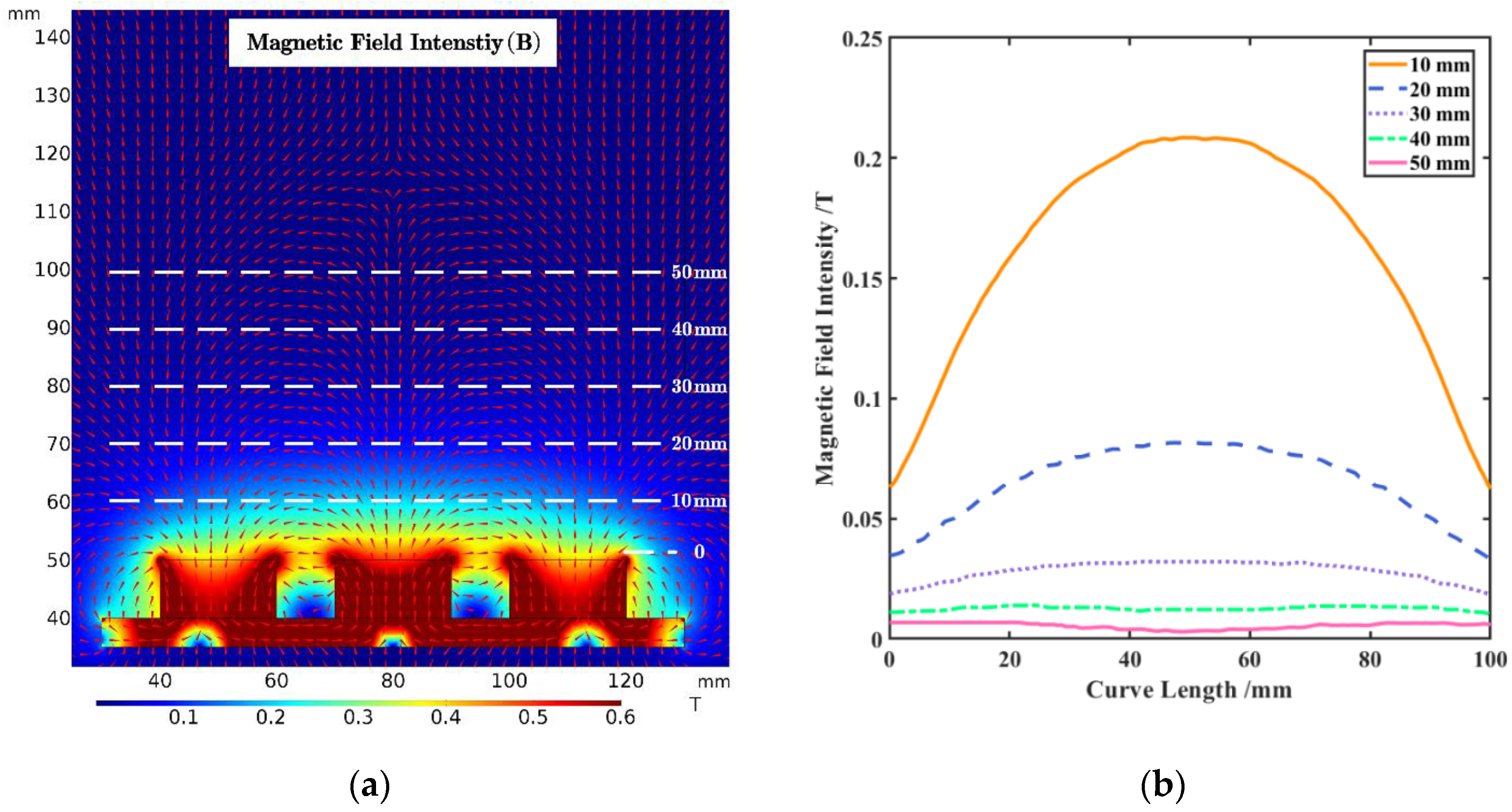
Specific simulation parameters for the 2D model of the magnetic system are shown in Table 1, and the simulated magnetic field is presented in Figure 4.
As shown in Figure 4a, the magnetic field intensity at the same distance on one side of the separation zone is relatively uniform and reaches 0.52T on the central surface of the magnetic pole. However, the magnetic field intensity decreases rapidly away from the magnetic pole surface (as shown in Figure 4b). Therefore, different magnetic field distributions in the separation zone can be obtained by adjusting the distance between the porous plate and magnetic pole surface to meet different separation needs.
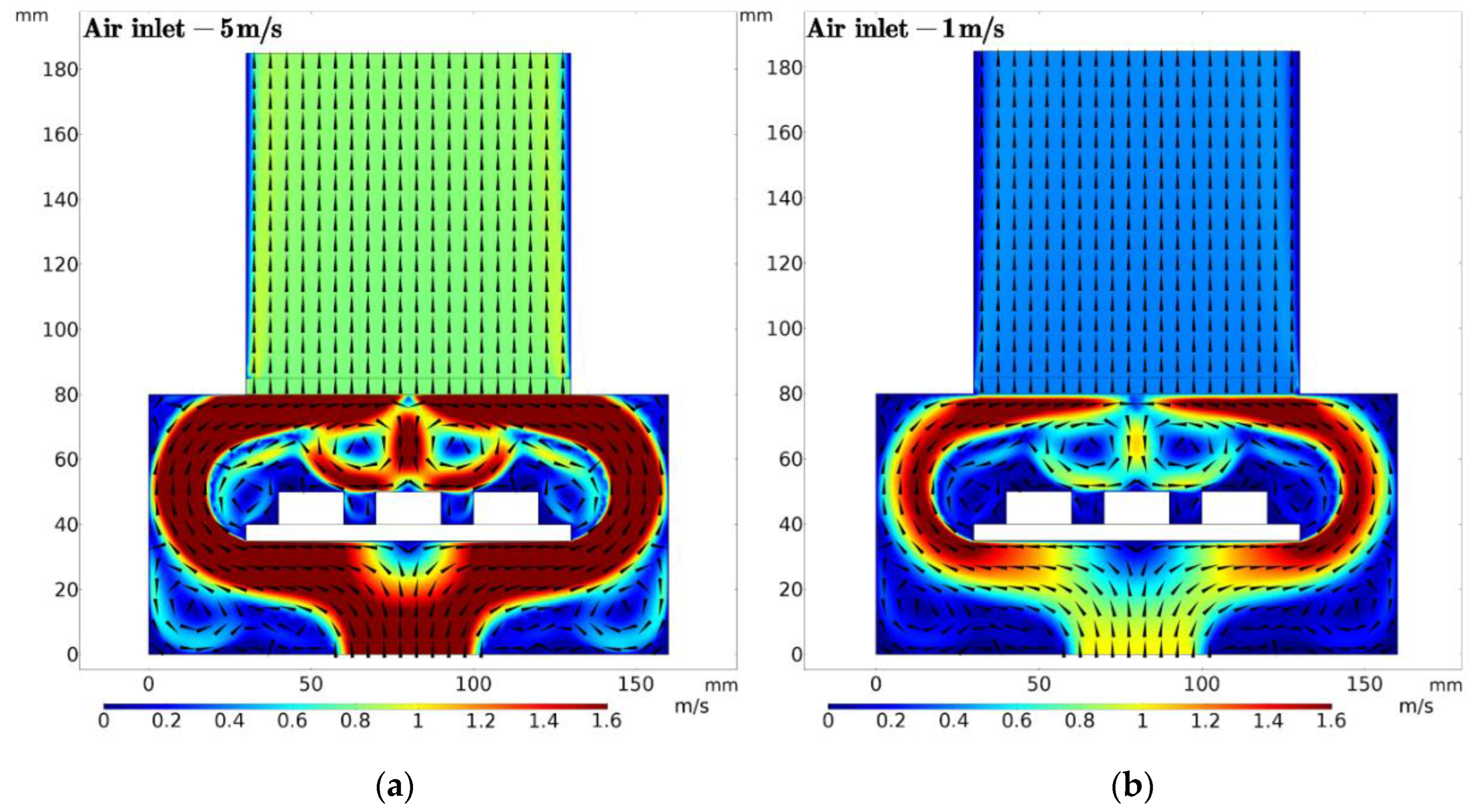
The specific simulation parameters are shown in Table 2. Figure 5 shows the steady-state flow field distribution under different airflow inlet velocities.
It can be seen from Figure 5 that the airflow velocity decreases slowly after entering the separation zone through the porous plate. The airflow velocity distribution in the separation zone is also relatively uniform parallel to the porous plate, which is favorable for particle separation. The fluid distribution of the outer basin is the same in Figure 5a,b, but the absolute magnitude of the airflow velocity differs, one being around 1m/s and the other being about 0.4 m/s.

3.2. Matching of Compound Forces

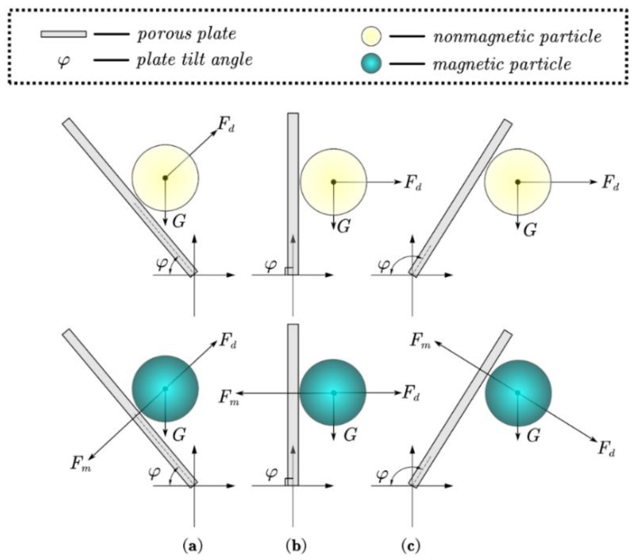
Good optimization of the synergistic effect of the compound forces is the key to improving the separation efficiency. In DPFMS, this synergistic effect is reflected by the relationship among the magnetic force (Fm), gravity force (G), and air drag force (Fd), which changes with the separation angle (φ). Figure 6 shows the forces on individual suspended magnetic and non-magnetic particles at different separation angles (i.e., the inclination angle of separation plane). Evidently, DPFMS have different separation performances at different separation angles, which can be characterized by the differences in the magnitude and direction of resultant forces acting on magnetic and non-magnetic particles.
To illustrate the particular role of airflow in improving the separation efficiency, spherical magnetite and quartz particles with a specific diameter of 100 μm were taken as representatives for force calculation and analysis with increasing airflow velocity under a magnetic field intensity of 270Gs.
Magnitude and direction of resultant acceleration were taken as the characterization to explain the tendency of particle movement. The magnitude can be expressed as Equation (11). The included angle between the resultant acceleration of quartz and magnetite (θb) was also calculated by Equation (12) for further illustrating the role of airflow in magnetic separation.
{ d u m d t = F m + G m + F d ρ m π d 3 6 d u q d t = G q + F d ρ q π d 3 6
θ b = 180 π arctan ( G m F d cos φ + F m cos φ F d sin φ F m sin φ ) 180 π arctan ( G q F d cos φ F d sin φ )
The included angles of θb calculated based on Equation (12) under different airflow velocities were presented in Figure 7.
In general, a small value of θb means that quartz and magnetite particles will move in a similar direction, which makes it difficult for the separation of magnetite from quartz. On the contrary, a large value of θb means that quartz and magnetite particles will move in opposite directions, which is beneficial for separation. As shown in Figure 7, the change in θb is remarkable at different airflow velocities and separation angles. A high airflow velocity improves the separation efficiency of magnetite and quartz at small separation angles while it reduces separation efficiency at large separation angles.

3.3. Particle Trajectory Analysis

As seen in Figure 4, the farther away from the magnetic system, the smaller the magnetic field intensity and the smaller the magnetic force received by the particles, and the closer to the magnetic system, the greater the decrease in magnetic force. Figure 5 shows that the airflow velocity is relatively constant, resulting in little difference in the fluid drag force on the particles throughout the separation zone. In addition, gravity remains unchanging. As a result, the farther away from the separation surface, the more easily the movement of particles is dominated by airflow drag; when close to the separation surface, magnetic force is the dominant force of magnetic particles.
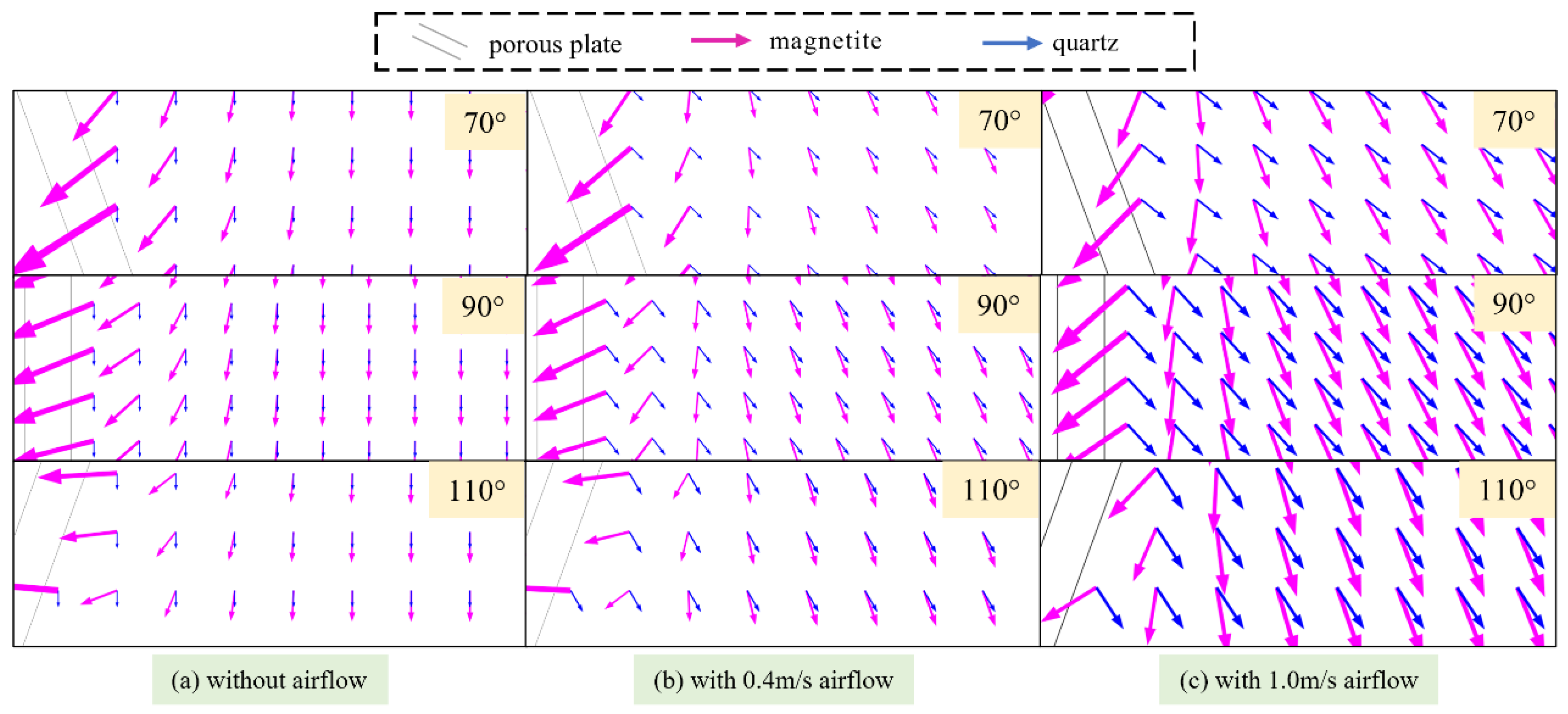
To obtain a more intuitive and thorough understanding of composite force field, three representative separation angles (70°, 90° and 110°) that allow particles to discharge smoothly were chosen. The resultant force distribution of magnetite and quartz particles in the separation zone with (0.4 m/s and 1.0 m/s) or without airflow was calculated and simulated, as shown in Figure 8. The resultant force on magnetite is roughly perpendicular to the separation plane while the resultant force on quartz depends largely on the airflow. The resultant force on quartz points away from the separation plane in the presence of airflow. At separation angles of 70° and 90°, introducing airflow is helpful for improving separation efficiency.
The motion of magnetite and quartz under different airflow velocities were calculated and simulated based on Equation (12). As shown in Figure 9, in the absence of airflow, both magnetite and quartz move towards the separation plane at the separation angle of 70°. When airflow was applied, quartz particles move away from the separation plane while magnetite particles move towards the separation plane; thus, the dry magnetic separation efficiency was improved. Proper airflow can promote separation, but excessive airflow will cause loss of magnetite. When the airflow velocity exceeds 1 m/s, if the feeding point is far away from the separation plane, magnetite may not be collected if the feeding point is far away from the separation plane, and the separation efficiency will be reduced.

3.4. Experimental Verification

Due to the limited capacity of the laboratory DPFMS’s air supply system, an airflow over the separation surface greater than 1 m/s is not possible. The magnetic field over the separation surface cannot be too strong to match the low airflow; hence, the following experiments used a 270 Gs magnetic field strength (measured by a Gauss meter).

3.4.1. Effects of Separation Angle on Particle Separation

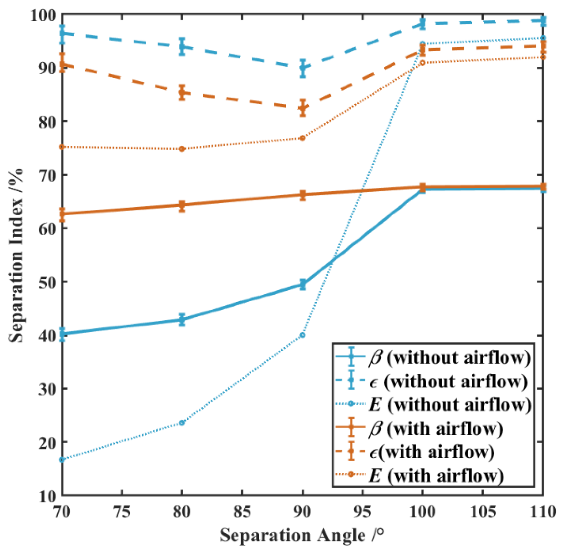
Separation experiments of artificial mixtures were carried out in the absence and presence of airflow. When the magnetic field intensity is 270 Gs (0.027T) and airflow velocity at the separation plane is 0.4 m/s (with airflow), separation indexes of artificial mixtures at different separation angles are shown in Figure 10.
Figure 10 shows that airflow improves the separation indexes at separation angles less than 100°. Besides the recovery of iron, the separation efficiency E and iron grade of magnetic concentrate increase with an increase in separation angle at an airflow velocity of 0.4 m/s. Airflow shows a negative effect on the separation index at a separation angle larger than 100°. It indicates that proper airflow velocity and separation angle are essential for particle separation.

3.4.2. Effects of Airflow Velocity on Particle Separation

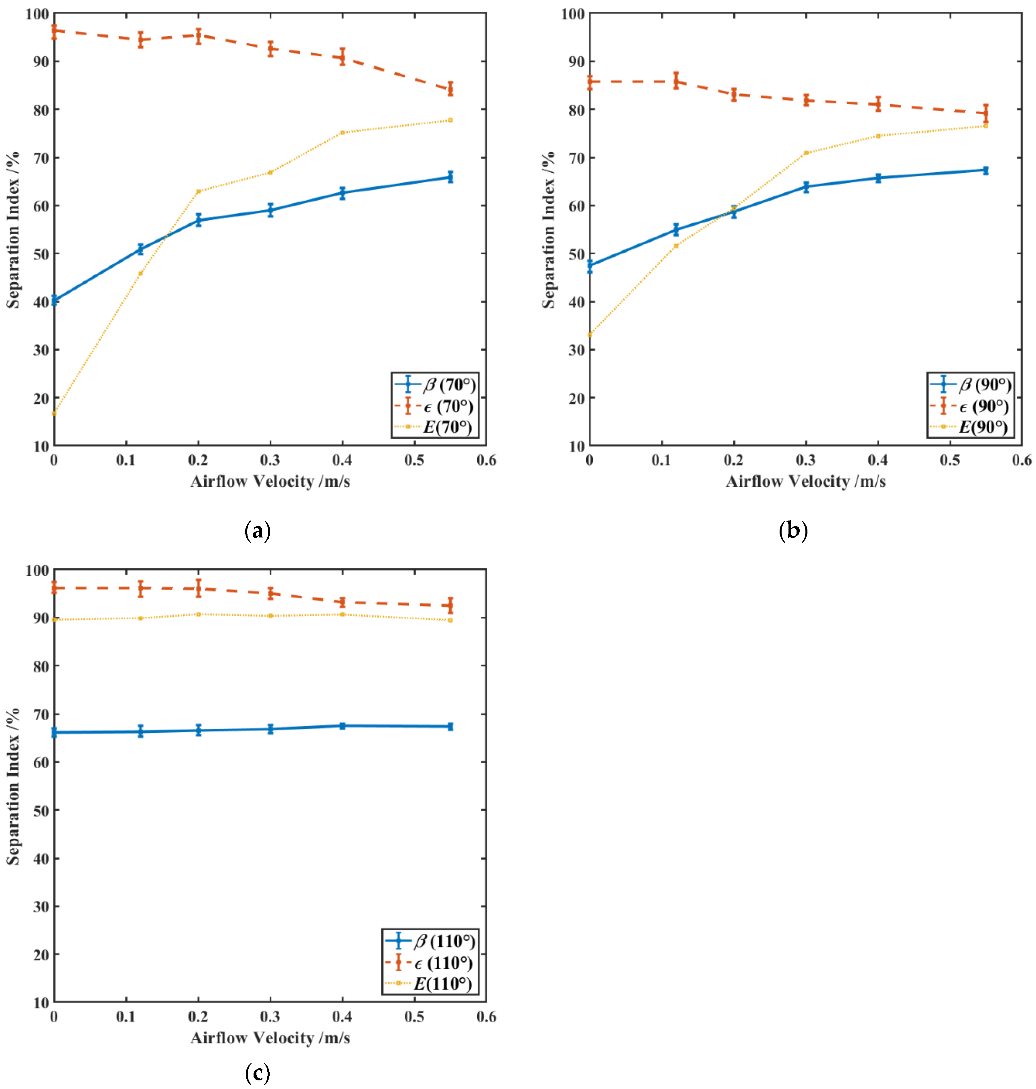
Furthermore, to clarify the suitable airflow velocity at a specific magnetic field intensity, separation tests were carried out at different airflow velocities. When the magnetic field intensity at the separation plane is 270 Gs, the effects of the airflow velocity on separation indexes under separation angles of 70°, 90° and 110° are shown in Figure 11.
At separation angles of 70° and 90°, the iron grade and separation efficiency increase significantly while iron recovery decreases slowly with the increase in airflow velocity. The iron grade increases from 40.20% and 47.50% to 65.92% and 67.39%, and the separation efficiency increases from 16.68% and 33.09% to 77.72% and 76.54%, respectively. As shown in Figure 11, when the separation angle is less than 110°, the iron grade and separation efficiency both increase with the increase in airflow velocity, with the optimal airflow velocity at 0.4 m/s. The higher airflow velocity shows negligible effects on the separation index of artificial mixtures when the separation angle is over 110°. Because the separation efficiency at large separation angles is already quite high without airflow and too strong airflow will encourage some magnetic particles to enter the tailings, the iron recovery and separation efficiency both show a decreasing trend at a high airflow velocity (greater than 0.2 m/s). When 0.6 m/s airflow was applied, the separation efficiency dropped from 89.53% to 88.22% in comparison to no airflow.

4. Conclusions

Introducing airflow has been proven to be an effective way to improve the separation efficiency of dry magnetic separation, especially for fine-grained materials. A laboratory dry pneumatic flat magnetic separator (DPFMS) applying airflow in the opposite direction of magnetic force was designed and manufactured. An artificial mixture of magnetite and quartz with the size range of −0.15 + 0.074 mm was used to test and investigate the separation performance and mechanism. A good separation index can be achieved when the separation angle is less than 90° at an airflow velocity of 0.4 m/s. Calculation and simulation of forces on magnetite and quartz show that airflow applied in the opposite direction of magnetic force has further expanded the force and movement difference between magnetite and quartz particles, which can significantly improve the efficiency of dry magnetic separation of fine-grained magnetite. It is clear that a larger airflow velocity is not more beneficial to separation. When the separation angle is small (70°, 90°), the large airflow velocity is helpful for strengthen the separation, but when the separation angle is large (110°), the excessive airflow velocity will reduce the separation efficiency. This work also demonstrates that in PDMS, the airflow velocity on the drum surface should be regulated in a suitable range, as being too large or too small is undesirable for separation. Furthermore, the airflow velocity in the bottom of the drum should be smaller than that in the upper regions to achieve consistent and stable separation conditions.

Author Contributions

Conceptualization, X.L. and Y.W.; methodology, Y.W.; software, X.L. and X.Z.; validation, X.L. and D.L.; formal analysis, X.L.; investigation, X.L.; resources, X.L.; data curation, X.L.; writing—original draft preparation, X.L.; writing—review and editing, Y.W., X.Z. and D.L.; visualization, X.L.; supervision, Y.W.; project administration, X.L.; funding acquisition, Y.W. and D.L. All authors have read and agreed to the published version of the manuscript.

Funding

This work was supported by the National Key Research and Development Program of China (No. 2021YFC2903202), the National Natural Science Foundation of China (Grant No. 51674290, No. 51804341, No. 51974366, No. 52174267, and No. 52174270.), the Natural Science Foundation of Hunan Province (Grant No. 2016JJ3150 and No. 2019JJ50833), and the Key Laboratory of Hunan Province for Clean and Efficient Utilization of Strategic Calcium-containing Mineral Resources (No. 2018TP1002).

Conflicts of Interest

The authors declare no conflict of interest. The funders had no role in the design of the study; in the collection, analyses, or interpretation of data; in the writing of the manuscript, or in the decision to publish the results.

References

  1. Chizhevsky, V.B. Study of Fine Material Dry Magnetic Separation Process in Suspension State. Miner. Sep. 2006, 2, 25–28. [Google Scholar]
  2. Tripathy, S.K.; Banerjee, P.K.; Suresh, N.; Murthy, Y.R.; Singh, V. Dry High-Intensity Magnetic Separation In Mineral Industry—A Review Of Present Status And Future Prospects. Miner. Process. Extr. Metall. Rev. 2017, 38, 339–365. [Google Scholar] [CrossRef]
  3. Chen, L.; Liao, G.; Qian, Z.; Chen, J. Vibrating High Gradient Magnetic Separation for Purification of Iron Impurities under Dry Condition. Int. J. Mineral Process. 2012, 102–103, 136–140. [Google Scholar] [CrossRef]
  4. Demidov, I.V.; Vaisberg, L.A.; Blekhman, I.I. Vibrational Dynamics of Paramagnetic Particles and Processes of Separation of Granular Materials. Int. J. Eng. Sci. 2019, 141, 141–156. [Google Scholar] [CrossRef]
  5. Xu, J.; Chen, J.; Ren, X.; Xiong, T.; Liu, K.; Song, S. A Novel Dry Vibrating HGMS Separator for Purification of Potash Feldspar Ore. Sep. Sci. Technol. 2021, 57, 484–491. [Google Scholar] [CrossRef]
  6. Augusto, P.A.; Augusto, P.; Castelo-Grande, T. Magnetic Shielding: Application to a New Magnetic Separator and Classifier. J. Magn. Magn. Mater. 2004, 272–276, 2296–2298. [Google Scholar] [CrossRef]
  7. Lindner, J.; Nirschl, H. A Hybrid Method for Combining High-Gradient Magnetic Separation and Centrifugation for a Continuous Process. Sep. Purif. Technol. 2014, 131, 27–34. [Google Scholar] [CrossRef]
  8. Zeng, J.; Chen, L.; Yang, R.; Tong, X.; Ren, P.; Zheng, Y. Centrifugal High Gradient Magnetic Separation of Fine Ilmenite. Int. J. Miner. Process. 2017, 168, 48–54. [Google Scholar] [CrossRef]
  9. Dean, R.S.; Davis, C.W. Method of Separating Magnetic Material. US2132404A, 11 October 1938. [Google Scholar]
  10. Martinez, E. Gravity-Magnetic Ore Separators and Methods. US4659457A, 21 April 1987. [Google Scholar]
  11. Yu–Shu, Z.; De–Zhang, L.; Shuyi, L. A Study of Magnetic Aggregation—Gravity Separation for Separation of Coarse Magnetite Ores. Magn. Electr. Sep. 1997, 8, 69–79. [Google Scholar] [CrossRef]
  12. Ali-Zade, P.; Ustun, O.; Vardarli, F.; Sobolev, K. Development of an Electromagnetic Hydrocyclone Separator for Purification of Wastewater. Water Environ. J. 2008, 22, 11–16. [Google Scholar] [CrossRef]
  13. Cao, S.; Wei, D.; Li, J. Effect of Magnetic Field in Magnetic Separation Column on Particle Separation Process Based on Numerical Simulation. J. Eng. Sci. Technol. Rev. 2019, 12, 53–58. [Google Scholar] [CrossRef]
  14. Safikhani, H.; Allahdadi, S. The Effect of Magnetic Field on the Performance of New Design Cyclone Separators. Adv. Powder Technol. 2020, 31, 2541–2554. [Google Scholar] [CrossRef]
  15. Walker, M.S.; Devernoe, A.L. Mineral Separations Using Rotating Magnetic Fluids. Int. J. Miner. Process. 1991, 31, 195–216. [Google Scholar] [CrossRef]
  16. Lin, I.J.; Krush-Bram, M.; Rosenhouse, G. The Benefication of Minerals by Magnetic Jigging, Part 3. The Bed Effects and the Multifrequency Magnetic Jig. Int. J. Miner. Process. 1998, 55, 61–72. [Google Scholar] [CrossRef]
  17. Zhao, T.L.; Dai, S.J. Development of a New Type of Column Magnetic Separator. Adv. Mater. Res. 2013, 826, 25–28. [Google Scholar] [CrossRef]
  18. Brandner, E.D.; Jamison, R.E. VacuMag Magnetic Separator and Process. US7681736B2, 23 March 2010. [Google Scholar]
  19. Nakai, Y.; Mishima, F.; Akiyama, Y.; Nishijima, S. Development of High Gradient Magnetic Separation System under Dry Condition. Phys. C Supercond. Appl. 2010, 470, 1812–1817. [Google Scholar] [CrossRef]
  20. Kozlova, E.V.; Skrypnikov, A.V.; Kozlov, V.G. Air Magnetic Separator for the Preparation of Forestry Seed Material and Its Theoretical Justification. In Proceedings of the Materials Science and Engineering, Novosibirsk, Russian, 12–14 December 2018; IOP Publishing Ltd: Bristol, UK, 2018; Volume 560, pp. 1–6. [Google Scholar]
  21. Song, S.; Zhang, G.; Luo, Z.; Lv, B. Development of a Fluidized Dry Magnetic Separator and Its Separation Performance Tests. Miner. Process. Extr. Metall. Rev. 2019, 40, 307–313. [Google Scholar] [CrossRef]
  22. Tang, D.; Wang, F.; Dai, H. Dynamic Behavior of Fine Particles in Dry Medium-Intensity Magnetic Separator Based on k–ε Turbulence Model and Low Reynolds Number k–ε Turbulence Model. Sep. Sci. Technol. 2021, 56, 1383–1396. [Google Scholar] [CrossRef]
  23. Lu, D.; Liu, J.; Cheng, Z.; Li, X.; Xue, Z.; Li, S.; Zheng, X.; Wang, Y. Development of an Open-Gradient Magnetic Separator in the Aerodynamic Field. Physicochem. Probl. Miner. Process. 2020, 56, 13. [Google Scholar] [CrossRef]
  24. Li, X.; Wang, Y.; Lu, D.; Zheng, X.; Gao, X. Optimization of Airflow Field for Pneumatic Drum Magnetic Separator to Improve the Separation Efficiency. Minerals 2021, 11, 1228. [Google Scholar] [CrossRef]
  25. Bars, M.L.; Worster, M.G. Interfacial Conditions between a Pure Fluid and a Porous Medium: Implications for Binary Alloy Solidification. J. Fluid Mech. 2006, 550, 149–173. [Google Scholar] [CrossRef] [Green Version]
  26. Svoboda, J. Magnetic Techniques for the Treatment of Materials; Kluwer Academic Publishers: Dordrecht, The Netherlands, 2004; ISBN 978-1-4020-2038-4. [Google Scholar]
  27. Bagchi, P.; Balachandar, S. Inertial and Viscous Forces on a Rigid Sphere in Straining Flows at Moderate Reynolds Numbers. J. Fluid Mech. 2003, 481, 105–148. [Google Scholar] [CrossRef]
  28. Guan, X.; Li, X.; Yang, N.; Liu, M. CFD Simulation of Gas-Liquid Flow in Stirred Tanks: Effect of Drag Models. Chem. Eng. J. 2020, 386, 121554. [Google Scholar] [CrossRef]
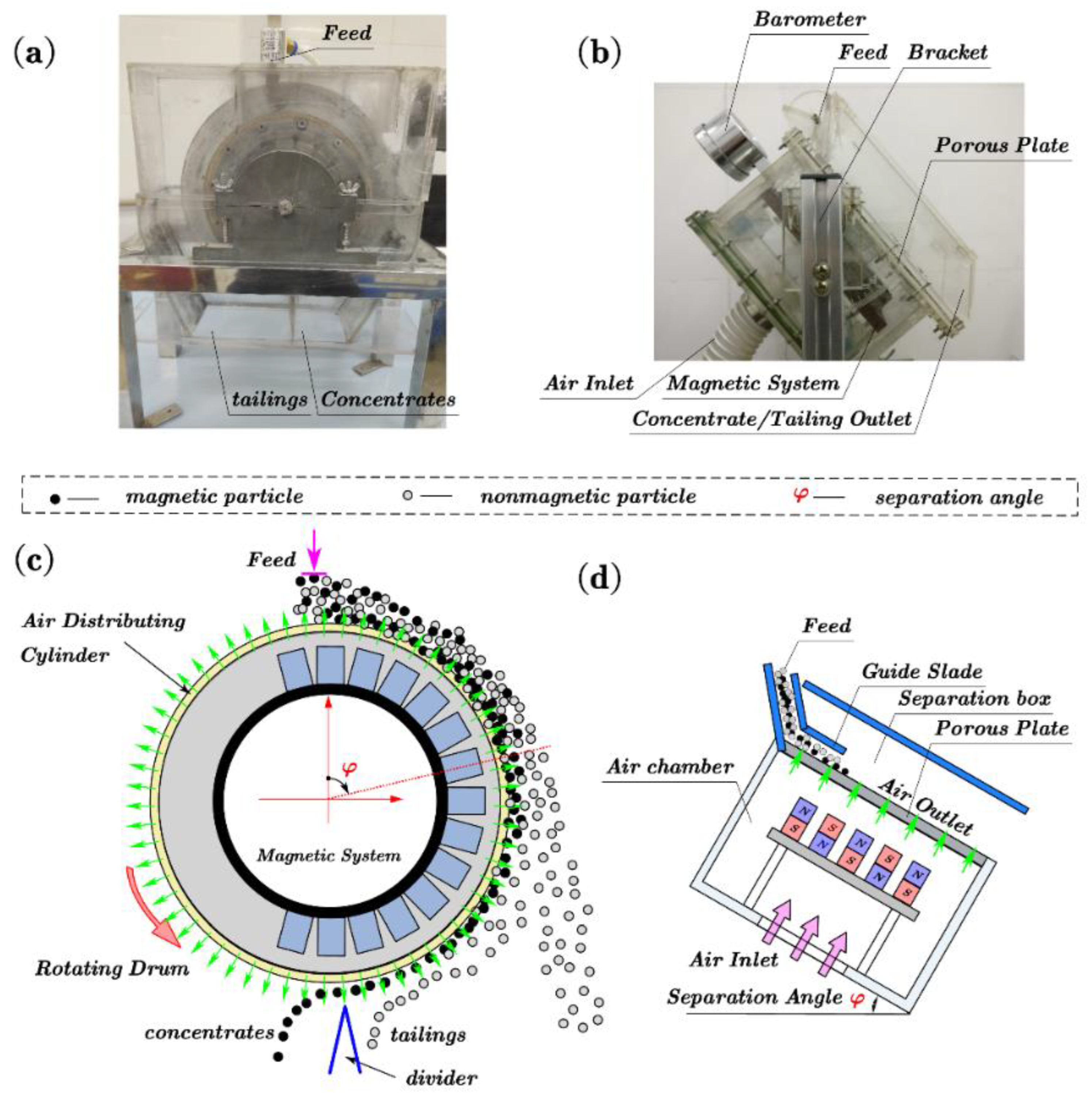
Figure 1. Structure of PDMS and DPFMS. (a,b): actual photo; (c,d): 2D structure diagram.
Minerals 12 01192 g001
Figure 2. SEM (a) and binary grayscale (b) image of microporous plate.
Minerals 12 01192 g002
Figure 3. A 3D structural model (a) and 2D simulation model (b) of DPFMS.
Minerals 12 01192 g003
Figure 4. The distribution of magnetic field intensity(B) of DPFMS. (a): B in separation zone; (b): B at various distance from the magnetic poles.
Minerals 12 01192 g004
Figure 5. Airflow velocity distribution in different zones with (a) 5 m/s and (b) 1 m/s airflow inlet.
Minerals 12 01192 g005
Figure 6. Schematic diagram of forces on particles under different separation angles φ (separation angles in (a), (b) and (c) are <90, =90 and >90, respectively).
Minerals 12 01192 g006
Figure 7. Angle θb between the resultant acceleration of magnetite and quartz.
Minerals 12 01192 g007
Figure 8. The resultant force distribution of magnetite (violet) and quartz (blue) particles.
Minerals 12 01192 g008
Figure 9. The movements of magnetite and quartz particle at the airflow velocity of 0, 0.4 m/s, 1 m/s (the green line represents the separation plane, the red dots represent magnetite, and the blue dots represent quartz).
Minerals 12 01192 g009
Figure 10. Separation indexes of artificial mixture vs. separation angles of DPFMS with and without airflow (β, ε, E stand for iron grade, recovery, and separation efficiency, respectively).
Minerals 12 01192 g010
Figure 11. Airflow velocity vs. separation index under different separation angles of (a) 70°, (b) 90°, and (c) 110° (β, ε, E stand for iron grade, recovery and separation efficiency, respectively).
Minerals 12 01192 g011
Table 1. Initial parameters of magnetic system.
ItemUnitValue
Magnetic yoke height/widthmm5/100
Pole height/widthmm10/20
Distance between adjacent polesmm10
Residual magnetism of magnetT1.19
Relative permeability of magnet 1.05
Relative permeability of the yoke iron B-H curve of DT4A
Table 2. Initial parameters of airflow field.
ItemUnitValue
Porous plate height/widthmm5/100
Air chamber height/widthmm80/160
Air inlet widthmm40
Porosity of porous plate, εp%22.46
Permeability of porous plate, κm21.93 × 10−11
Dynamic viscosity of air (25 °C), ημPa·s18.448
Density of air (25 °C), ρfkg·m−31.169
Publisher’s Note: MDPI stays neutral with regard to jurisdictional claims in published maps and institutional affiliations.