Article

THM Response in the Near Field of an HLW Disposal Tunnel in the Callovo-Oxfordian Clay Host Rock Caused by the Imposed Heat Flux at Different Water Drainage Conditions

Nuclear Engineering Laboratory, Lithuanian Energy Institute, 3 Breslaujos str., 44403 Kaunas, Lithuania
*
Author to whom correspondence should be addressed.
Minerals 2022, 12(10), 1187; https://doi.org/10.3390/min12101187
Submission received: 29 June 2022 / Revised: 8 September 2022 / Accepted: 16 September 2022 / Published: 22 September 2022
(This article belongs to the Special Issue Coupled Processes in Clays: Experiments, Modeling, Applications)

Abstract

:
Heat load from high-level radioactive waste (HLW) packages will result in elevated temperatures around the disposal tunnel. Differences in thermal expansion between rock and water will induce the redistribution of stresses. The assessment of the thermo-hydromechanical (THM) regime is necessary to evaluate the potential for fracture development. For this purpose, it is important to evaluate the nature and extent of induced strains, and their impact on rock permeability, which, subsequently, is important for radionuclide transport. This paper presents the modeling activities of the Lithuanian Energy Institute performed in the framework of the European joint program EURAD and the analysis of the influence of temperature on clay-based material behavior. Within this study, different stress conditions and material properties (isotropic, anisotropic) were analyzed with a thermo-poroelastic material model for the Callovo-Oxfordian clay host rock in the 100 m × 100 m domain. The heat load on the clay rock comes from a tunnel with a radius of 1.25 m. The overall THM response of the clay host rock system to the heat load is performed with the COMSOL Multiphysics (Burlington, MA, USA) software. The THM response near the HLW disposal tunnel was analyzed in terms of temperature, pore pressure, displacements, and stresses, and the results are presented in this work. Besides the impact of anisotropy, the effect of hydraulic conditions at the tunnel boundary was also analyzed. The modeling results revealed that anisotropy in stress and properties had an impact on the hydro-mechanical response of the material even during excavation and waiting phases. The analysis also showed that the water drainage condition on the tunnel boundary had no effect on the thermal state around the tunnel, but it had a significant impact on the hydro-mechanical response.

1. Introduction

The international community has a unanimous agreement that geological disposal is a mature solution when it comes to the issue of HLW management. The development of disposal methods for spent nuclear fuel or vitrified HLW evolved from conceptual plans to detailed design specifications for construction. In Finland, the construction license for the spent nuclear fuel encapsulation plant and final disposal facility at Olkiluoto was granted by the Finnish government in 2015 [1], and the facility has been under construction since then. The start of the operation of this deep geological repository (DGR) is expected within this decade. At the end of 2021, Posiva Oy submitted the license application for the operation of the encapsulation and final disposal facility [2]. In 2022, the Government of Sweden allowed SKB, the Swedish Nuclear Fuel and Waste Management Co., to construct a DGR for used nuclear fuel in Forsmark and an encapsulation plant in Oskarshamn [3]. In France, the license application for the DGR construction is underway for submission for regulatory review.
Being intensively investigated in Finland and Sweden, crystalline rock is not the only possibility considered for the geological repository. Among the potential host rocks, clay-based rocks have been extensively investigated over the last three decades. For this reason, underground research laboratories (URL) are constructed in Boom clay (HADES URL in Mol, Belgium), Callovo-Oxfordian claystone (Meuse/Haute URL in Bure, France), Opalinus clay (the Mont Terri laboratory in Switzerland), etc.
A lot of research has been performed over the last decades to gain an understanding of complex coupled processes taking place in geological repositories. As is indicated in [4], a temperature increase in a water-saturated porous medium with low permeability causes thermal pressurization which is essentially the result of the difference between the thermal expansion coefficients of the pore water and the solid skeleton. Non-uniform pore pressure distribution will impact the existing hydraulic gradients. It could also influence the quantity of the flow through the rock as well as the flow direction and could, thus, potentially affect the advective transport of radionuclides from the radioactive waste [5]. According to [6], the orientation of clay particles and aggregates within the Callovo-Oxfordian (COx) geological formation with respect to the bedding plane is not as marked as in the case of other indurated clays (e.g., Opalinus clay in Switzerland), and this leads to a slight anisotropy of most of the rock’s properties, particularity in terms of solute diffusion, water permeability, and mechanical parameters. It is also indicated in [6] that heating-induced pore pressure increases and that the COx THM behavior is anisotropic [7]. According to [8], in the case of the COx claystone, as with other claystones, there is a strong dependence of the mechanical behavior on confining pressure (marked by a transition from a brittle towards a ductile behavior, with transition stress between two modes of failure of about 20 MPa). Along with the importance of confining pressure, the COx material failure and fracturing also need to be investigated if pore pressure exceeds the tensile resistance of the rock. In the laboratory tests reported in [9], the failure happened at average axial effective tensile stresses of around 3.0 MPa. Creep was analyzed in [10] among other important processes for the THM behavior in COx formation. Considering existing different approaches for creep representation in numerical modeling in [10], an assumption was accepted that creep reduces the pore pressure increase compared to the poroelastic approach. The above-mentioned aspects of the COx THM behavior inevitably led to a broad experimental investigation program.
Andra (France) has been conducting an important research program since 2005 to investigate the THM response of the COx formation to thermal load through laboratory and in situ experimentations. The experiments started from small-scale heating boreholes (TED experiment) and have extended to full-scale (ALC experiments) [5]. The most recent finished in-situ test in the COx formation was “ALC1604”. In 2020, heating was started in a new experiment labeled “ALC1605”. The THM response of Cox clay will be measured during this experiment and also interpreted by researchers within the framework of the European joint program EURAD [11].
Besides experimental investigations, scientists also conduct numerical analysis of coupled THM processes in COx claystone. Numerous studies have been performed on the experiments from the small scale to in-situ scale over different time scales [5,12,13,14,15,16,17,18,19,20,21,22]. Some parts of numerical analysis have been devoted to predicting the COx THM behavior in the repository scale [23,24,25,26,27]. Different constitutive models have been developed and used to interpret experimental data on COx THM behavior. Classical continuum mechanical models range from thermo-poro-elastic models [5,12,13,14,15,20,23,24,25,26,28] to more complex elasto-plastic models [18], and elasto-visco-plastic models with consideration of strain localisation, damage, and creep [22,27,29,30,31]. In their studies, authors propose models based on continuum mechanics to represent tensile and shear damage in COx claystone [32] or models based on the phase field method or models considering micro-structural composition [33].
The modeling of in-situ experiments has several approaches for the representation of heaters, casings, and gaps in the experiments. Most commonly, these parts of an experimental set-up are not explicitly represented in the modeling and only heat flux or temperature to the rock contact with heaters is specified [5,12,15,16]. Some efforts, however, have been made to represent heaters and casings precisely [13,15,17,19] or at least indicated that they are lumped into equivalent porous material [20,21]. At the same time, hydraulic-mechanical conditions imposed by heaters and casings are treated differently: intermediate drained conditions on the borehole walls were imposed by modeling a porous medium with higher permeability [14]; undrained conditions were imposed [15]; draining conditions were imposed by fixing pore pressure to atmospheric pressure [5,12,15,21,29]; zero normal displacement was allowed [5,29]; flexible support was represented by a load on the tunnel boundary retained at a certain level [28]; free displacement conditions were imposed [12,20]. The importance of water drainage conditions (drained or undrained) and their impact on the pore pressure increase are mentioned in [15,18]. Besides, the excavation process and its impact on the stress state before heating is not considered in any of the mentioned modeled cases except [22].
It is commonly accepted that geological disposal must rely on multiple safety functions provided by engineered and natural barriers. Having a fine-grained, homogeneous pore structure and a self-sealing capacity, low permeability clay host rocks are able to provide an efficient barrier to radionuclide transport, a suitable environment for the engineered barrier system, and contribute to the safety functions of the disposal facility. Therefore, the clay rock behavior under various repository conditions needs to be well known before facility construction. Such knowledge will make it possible to demonstrate the feasibility of the disposal concept and support repository design specifications as well as safety assessment.
Within this current study, the THM behavior of the COx clay host rock was analyzed at the repository near the field scale while considering the excavation-induced redistribution of stresses and pore pressure. The water drainage effect on the THM response in the near field domain was analyzed by setting different hydraulic conditions on the tunnel boundary (drained, undrained). The THM response was analyzed under different conditions: (a) isotropic stress state and isotropic material properties, and (b) anisotropic stress state and anisotropic material properties. This paper summarises LEI modeling results of anisotropy and the water drainage effect on the THM response in the near field of an HLW repository.

2. Methodology

As a part of the EURAD HITEC work package, a benchmark was organized to compare the response of different codes and the behavior of three clay host rocks: the Boom clay, the Callovo-Oxfordian claystone, and the Opalinus clay. In this study, the coupled THM behavior of the COx claystone was analyzed under different conditions:
  • Isotropic case: isotropic stress state and isotropic material properties;
  • Anisotropic case: anisotropic stress state and anisotropic material properties.
Besides taking into consideration the anisotropy in stress conditions and properties, additionally, two variants were analyzed in our study. Heating under drained conditions (DC variant) and heating under undrained conditions (UDC variant) were distinguished to test the impact of the hydraulic condition on the overall hydro-mechanical response of the rock.
As it has been mentioned above, the HLW heat emitted on porous media will induce thermal expansion of the porous material and the thermal expansion of porewater. Different thermal expansion properties will lead to induced volumetric strain, which will cause an additional water source/sink. Depending on the permeability of the porous media, the induced pore pressure increase will dissipate over time. In low permeability rock, the advective water flow rate will be very slow and it will take years for overpressure to dissipate in comparison to fast dissipation in permeable fractured rock. That means that the hydraulic and mechanical responses are closely coupled. On the other hand, changes in pore pressure affect the effective stresses in saturated porous media according to Terzaghi’s Theory. Changes in effective stresses will determine the strains in the material. In this way, these mentioned processes are interrelated and have to be considered in the numerical modeling.

2.1. Mathematical Model

The governing THM equations to be solved numerically are briefly described below. Heat is transferred in porous media via conduction and advective water flow:
ρ C p e f f T t = ρ w C p , w · v D T + · k e f f T
Here, T is temperature, ρ w is water density (kg/m3), v D is Darcy velocity (m/s), k e f f is the thermal conductivity coefficient (W/(m*K)).
ρ C p e f f = n ρ w C p , w +   1 n ρ s C p , s
Here, ρ C p e f f is the heat capacity of porous media, n is porosity (m3/m3), ρ s is solid density (kg/m3), C p , w , C p , s is the specific heat of the water and solid grains, respectively (J/(kg*K)).
The mass balance in porous media m w = n ρ w is governed by changes in porosity and water density [34]:
m w t = ρ w n · β l P + α B n K g P t + ρ w · α B d e v d t n · ρ w · β l T T t + ρ w ·   1 α B β T D 1 n β T g T t
Here, β l P χ f 1 K f is water compressibility (1/Pa), β l T is the volumetric thermal expansion coefficient of water, e v is volumetric strain, α B is the Biot coefficient, P is pore pressure (Pa), K g - is the bulk modulus of grains (solid), β T D is the volumetric thermal expansion coefficient of the porous medium (1/K), β T g is the volumetric thermal expansion coefficient of solid grains (1/K).
Then the equation of water flow through water-saturated porous media under non-isothermal conditions becomes:
ρ w S P t = k μ T P + Q T H + Q T M + Q H M
Here, S = n · β l P + α n K g is storage (1/Pa), k is intrinsic permeability (m2), μ T is temperature-dependent dynamic water viscosity (Pa*s), Q T H , is water sources/sinks.
Thermo-hydraulic processes coupling term Q T H :
Q T H = ρ w · n · β l T T t
Thermo-mechanical processes coupling term Q T M :
Q T M = ρ w · 1 α β T D 1 n β T g T t
Hydro-mechanical processes coupling term Q H M :
Q H M = ρ w ·   α d e v d t
The strains in porous media are governed by the effective stresses which are derived according to Biot’s theory of poroelasticity from total stresses and considering pore pressure:
σ = σ t α B · P
The thermal expansion of porous media is considered as elastic volumetric strains ε t h under the assumption that the thermal expansion coefficient of the porous rock ( β T D ) is equal to that of the solid grains of this rock ( β T g ):
ε t h = β T D d T = β T g d T

2.2. Numerical Model

The numerical model for solving these governing equations was implemented in COMSOL Multiphysics (USA) by adding the TH, TM, and HM coupling terms. COMSOL Multiphysics is a general-purpose platform for modeling a number of various processes and their applications. It contains conventional physics-based user interfaces, as well as interfaces for the definition of partial differential equations by the user. The defined system of partial differential equations is solved with the finite element method.

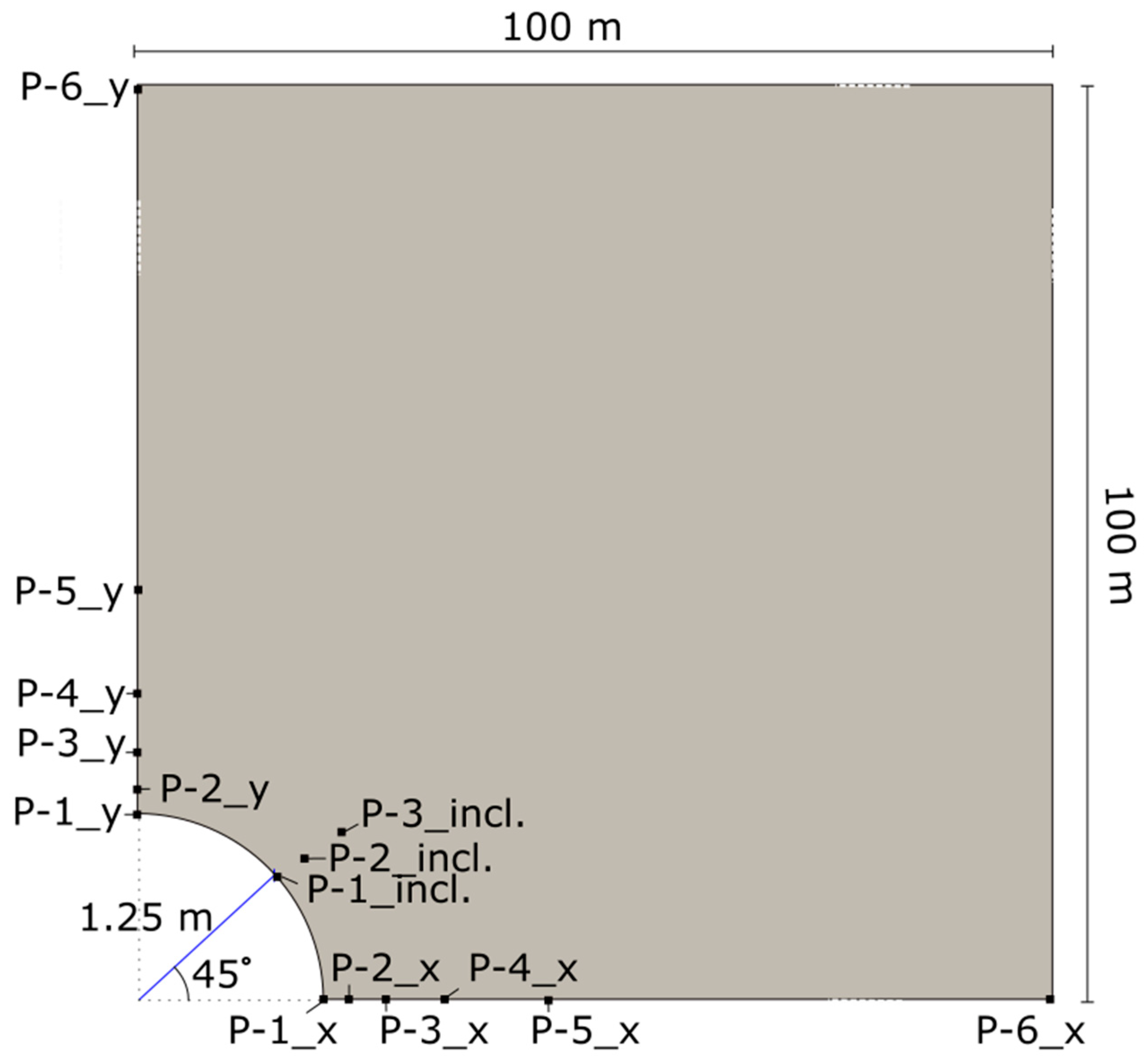
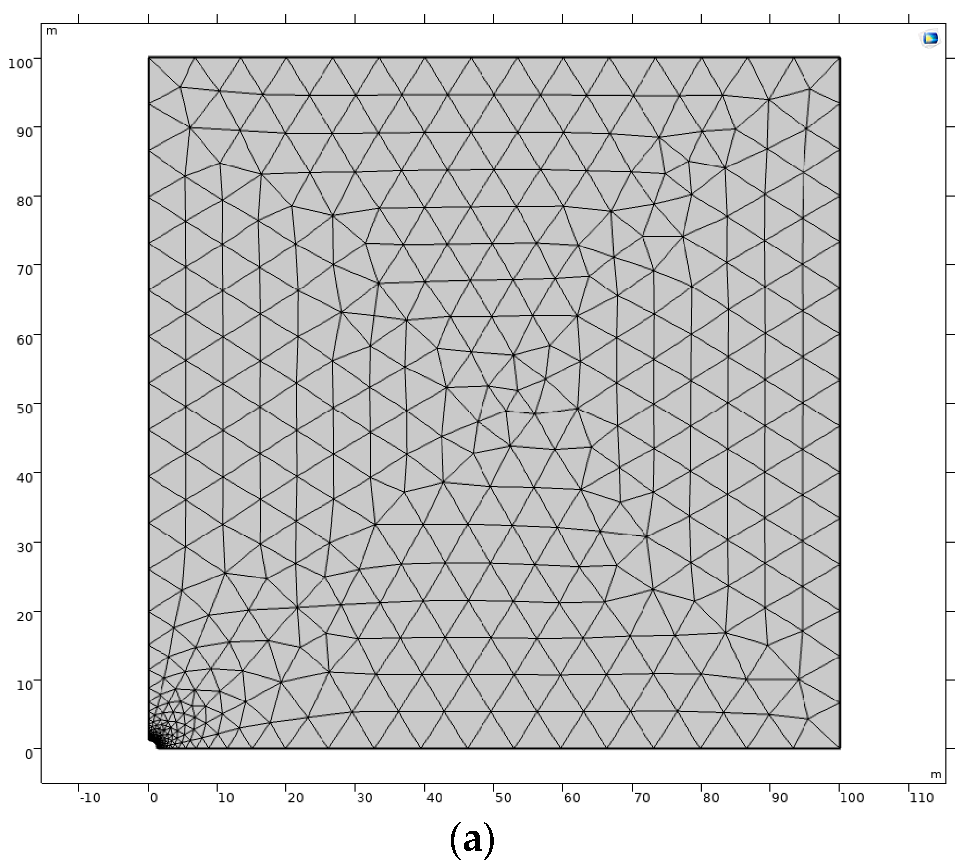
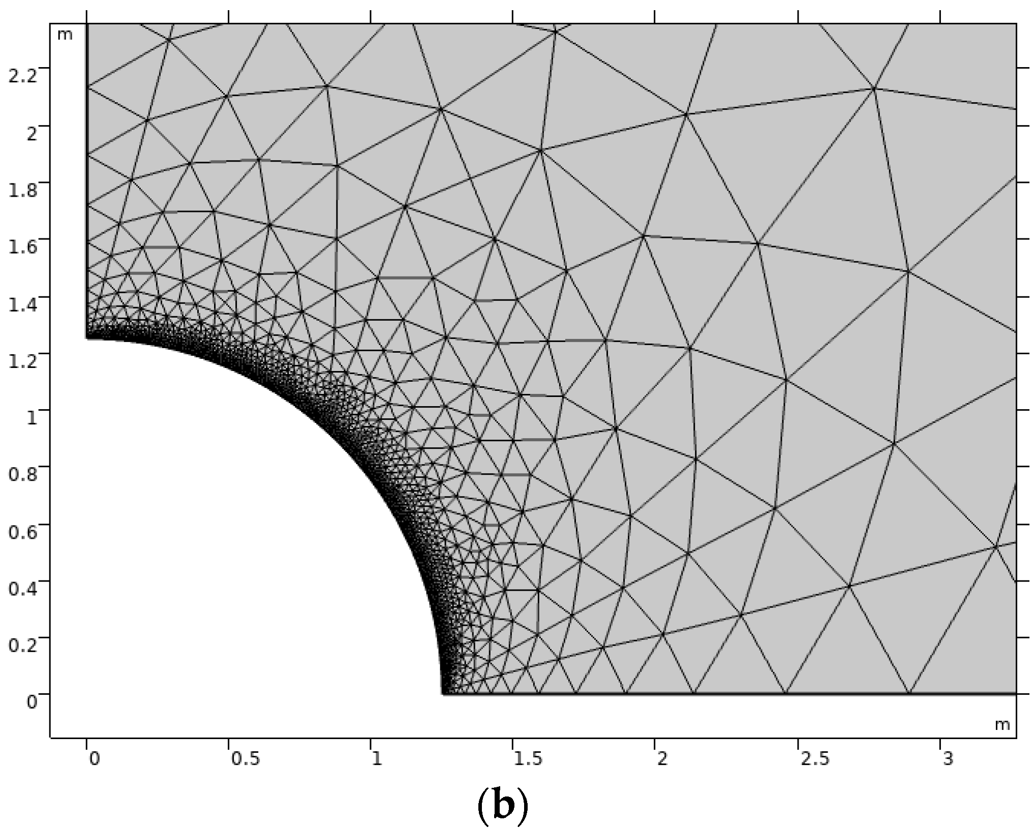
Geometry and Discretization

This work analyses a 100 m area of the COx clay rock around a disposal tunnel (R = 1.25 m) with the applied heat load. Due to symmetry, the modeling was done for only ¼ of the tunnel and the surrounding rock. Heat load was applied on the tunnel boundary (200 W/m). The model geometry is presented in Figure 1. It should be noted that the configuration used in this study (benchmark) is not identical to the concept of the French DGR (Andra’s project “Cigeo”). The French concept of the HLW repository consists of several parallel horizontal cells (with excavated diameter ~0.9 m) distributed within several hundreds of meters where exothermic waste packages will be emplaced (Plua et al. 2021).
For the analysis of THM response (Figure 1), we selected 6 main observation points in horizontal and vertical directions. In order to compare or analyze the results close to the tunnel wall (Table 1), we defined 3 auxiliary points located at 45 degrees from the x-axis (Figure 1) and additional points located within the distance between points P-1 and P-2.
The modeling domain was discretized uniformly into 3461 triangular mesh elements, as presented in Figure 2.

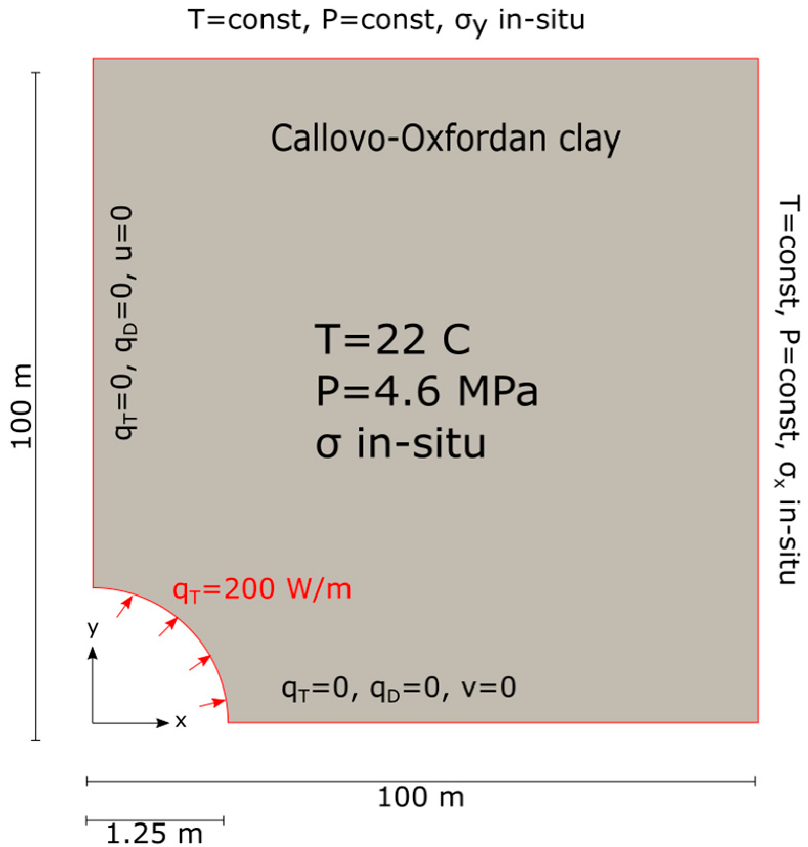
2.3. Initial and Boundary Conditions

We defined the following initial values for THM variables: T = 22 °C, P = 4.7 MPa, σxx, σyy = in-situ stress. Different stages were considered via the proper definition of boundary conditions:
  • excavation (duration of 1 day)
  • waiting phase (1–180 days)
  • heating phase (180–3650 days (10 years))
In order to model the excavation, we linearly decreased the stresses on the tunnel boundary EA (Figure 3) to 5% of the initial in-situ stress. Vertical and horizontal displacements were fixed on boundaries AB and DE, respectively. In-situ stress conditions were imposed on boundaries DC and BC via boundary load. Meanwhile, for representation of possible water drainage through the tunnel boundary during excavation, we reduced the pore pressure on boundary EA from the initial (4.7 MPa) to the atmospheric pressure (0.1 MPa) within 1 day (24 h). We assume that the pressure on all other boundaries was constant and equal to the pressure of in-situ (4.7 MPa).
In line with the benchmark specification [11], we did not change the boundary conditions during the waiting phase: the stresses on the tunnel boundary remained fixed at 5% of the in-situ stress (representing the possible structural tunnel support). The pore pressure was maintained at atmospheric pressure. For the heating phase, a constant heat flux (200 W/m) was applied on tunnel boundary EA. The heat flux was similar to the maximum heat output which could be expected for the HLW container to be disposed of in COx claystone. The stresses on the tunnel boundary remained fixed at 5% of the in-situ stress.
The impact of supporting structure (for example, tight or untight (for example, perforated) casing) on the hydraulic regime around the tunnel could provide different—drained (DC variant) and undrained (UDC variant)—conditions for water flow. For the DC variant, we left the pore pressure fixed on the tunnel wall, while for the UDC variant, we changed the fixed pore pressure on the tunnel wall to a no-flow boundary condition once the heating was started. Constant stresses and pore pressure were maintained on boundaries DC and BC. The in-situ stresses are summarized in Table 2.

2.4. Input Parameters

Particular THM response depends on rock-specific thermal, hydrogeological, and mechanical properties. These properties depend on the aspects related to the host rock geology, mineralogy, porewater composition, etc. As it is described in [35], the COx claystone was deposited 160 million years ago over a period of approximately five million years, in an open and calm marine environment. The formation is surrounded by the Dogger and the Oxfordian limestones. Being the most homogeneous and richest in argillaceous minerals (more than 40% on average), the geological argillaceous unit (UA) is an interesting formation from the perspective of DGR construction. This unit shows a relatively uniform structure beyond a few hundred µm. The texture is finely divided and is an assembly of tectosilicate and carbonate grains, connected by a fine matrix formed of clay minerals and calcite microcrystals. Both the tectosilicate and the carbonate grains show a preferential orientation of their long axis parallel to the sedimentation plane [35].
The thickness of this prospective argillaceous unit (UA) ranges from 100 to 120 m. As described in [35], the characterization of this porosity was performed using several techniques (mercury intrusion porosimetry, helium pycnometer, nitrogen adsorption, and water content), and it indicates that the network of pores mainly comprises meso- and micropores with a predominant pore size of approximately 10 to 30 nm. It also revealed that this network has extremely low connectivity for pore sizes greater than 40 µm. For pores of less than 3–4 nm, the water is influenced by the electrostatic field on the outer surface of the clay minerals, and is, therefore, relatively immobile. For larger pores, the porewater (free) is not affected by electrostatic interactions and will be mobile (will flow). Therefore, mineralogy highly influences rock permeability and leads to inherent spatial variability of COx properties. The effects of inherent spatial variability of COx properties on the THM responses of a high-level radioactive waste repository were analyzed in [29].
The main THM parameters were determined from laboratory tests and in-situ measurements [17]. According to [17], at the main level of the Meuse/Haute-Marne Underground Research Laboratory (MHM URL), located some 490 m deep in the middle of the COx claystone layer, porosity is approximately 18% with a very small mean pore diameter (about 0.02 μm) leading to a very low permeability (ranging between 5.0 × 10⁻²¹ m2 and 5.0 × 10⁻²⁰ m2) and a slight anisotropy ratio of about 3. The specific heat capacity of the solid phase is 800–820 J/(kg∙K), resulting in a specific heat capacity for the whole saturated material of about 1000 J/(kg∙K). The values for the thermal conductivity of the COx clay are about 1.9 W/(m∙K) parallel and 1.3 W/(m∙K) perpendicular to the bedding plane. The Young’s modulus perpendicular to the bedding is around 4.0 × 10⁹ Pa with the anisotropy ratio of 1.3: however, this ratio can reach 2 for some samples tested on triaxial tests.
Water and COx THM-related properties for this study are provided in specification [11] and summarised in Table 3 and Table 4.

3. Results and Discussion

The following sections describe the outcomes of the numerical model, which represent the coupled THM response in the vicinity of an HLW disposal tunnel as the result of heating under different conditions (drained, undrained). Firstly, we describe and discuss the evolution of temperature, pore pressure, stresses, and displacements over time. The role of anisotropy in stress and THM-related properties is analyzed. Then, we discuss the effect of water drainage (hydraulic condition) at the tunnel boundary on the overall THM response.

3.1. Heating under Drained Conditions

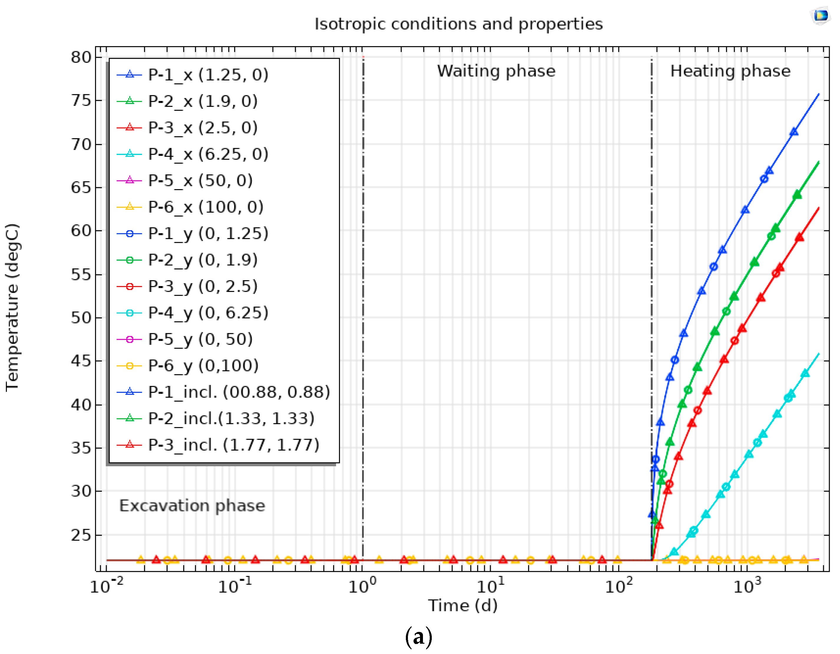
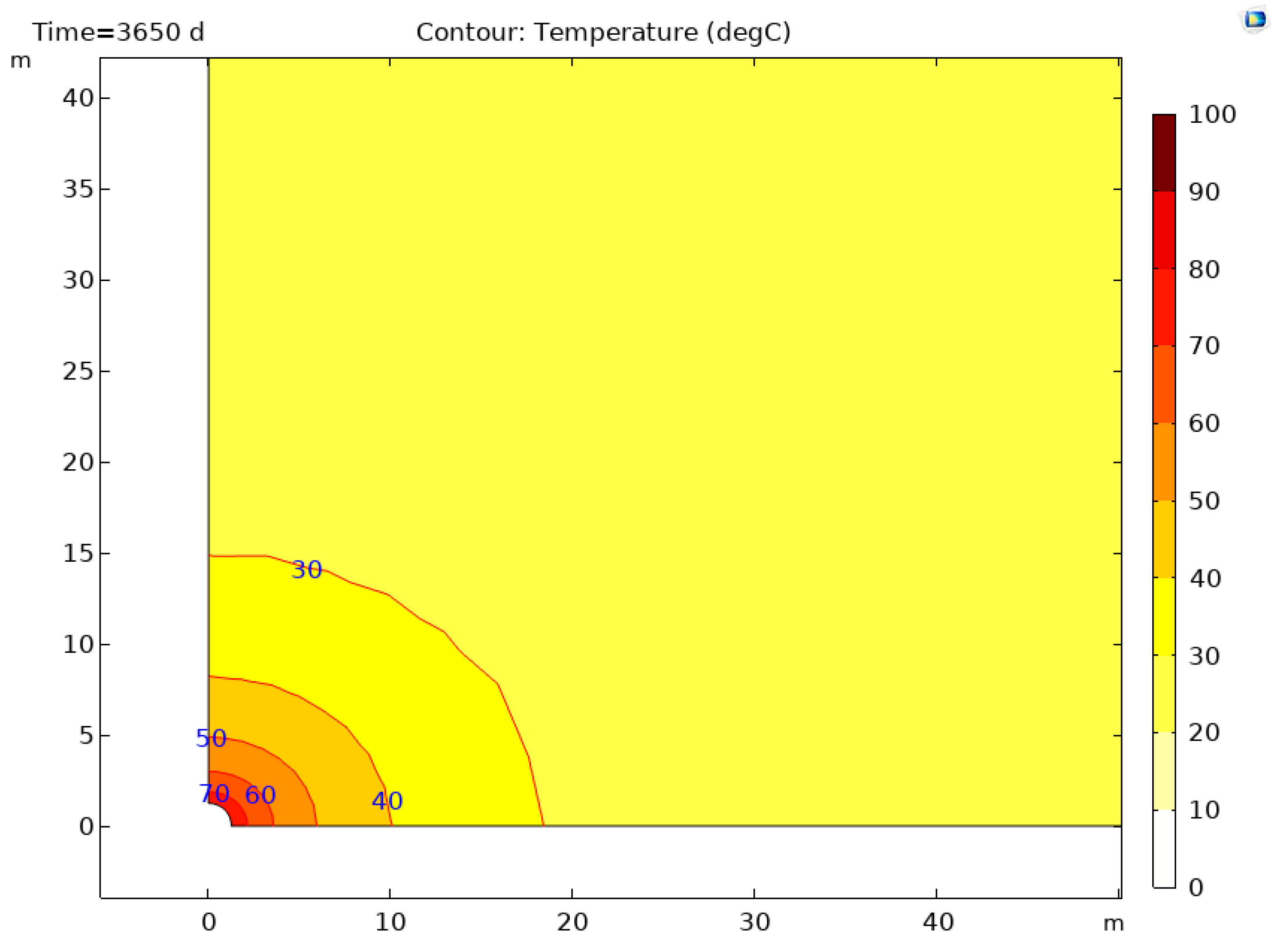
3.1.1. Thermal State

The modeling results showed that under isotropic stress conditions and with isotropic material properties, the highest temperature would not exceed 76 °C and was observed at the tunnel wall (Figure 4a).
The anisotropy in stress conditions and material properties led to higher temperature values at the analyzed points. On the other hand, the compared maximum temperatures by the end of the simulation at points P-1_x (point on the tunnel side,) and P-1_y (point on tunnel top) were the same and reached 79.6 °C. The temperature at a farther distance was slightly higher at the points situated from the tunnel in the horizontal direction compared to those located in vertical and inclined (45 degrees) directions. This indicated faster heat transfer in the horizontal direction driven by a higher thermal conductivity in parallel to the bedding direction. This confirms the anisotropic distribution of the temperature in the system with anisotropic stress and anisotropic properties.

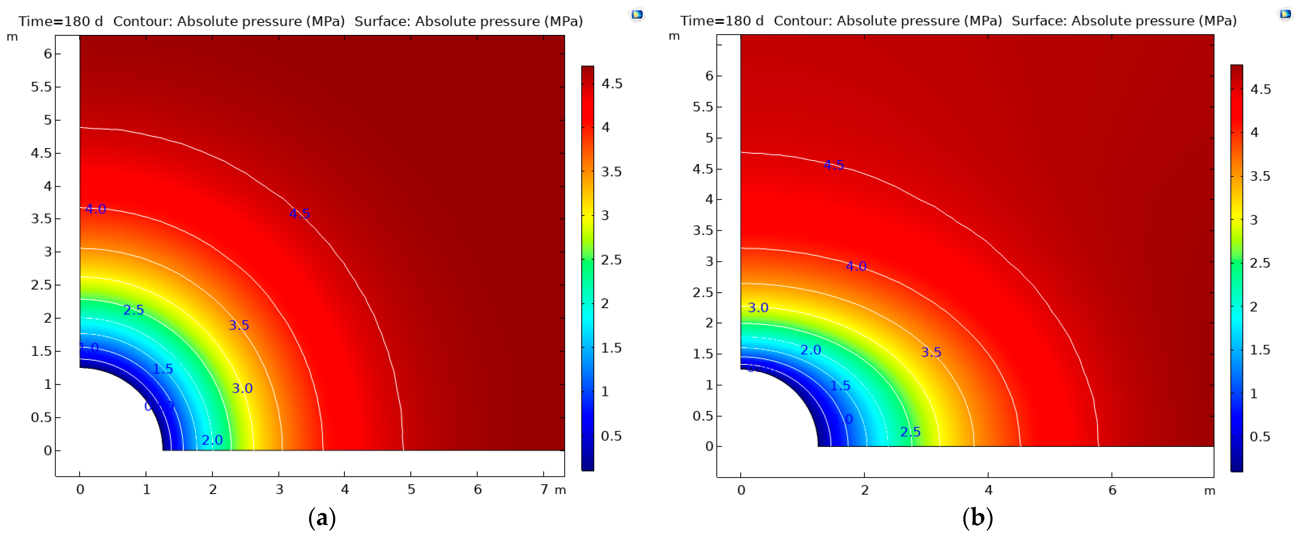
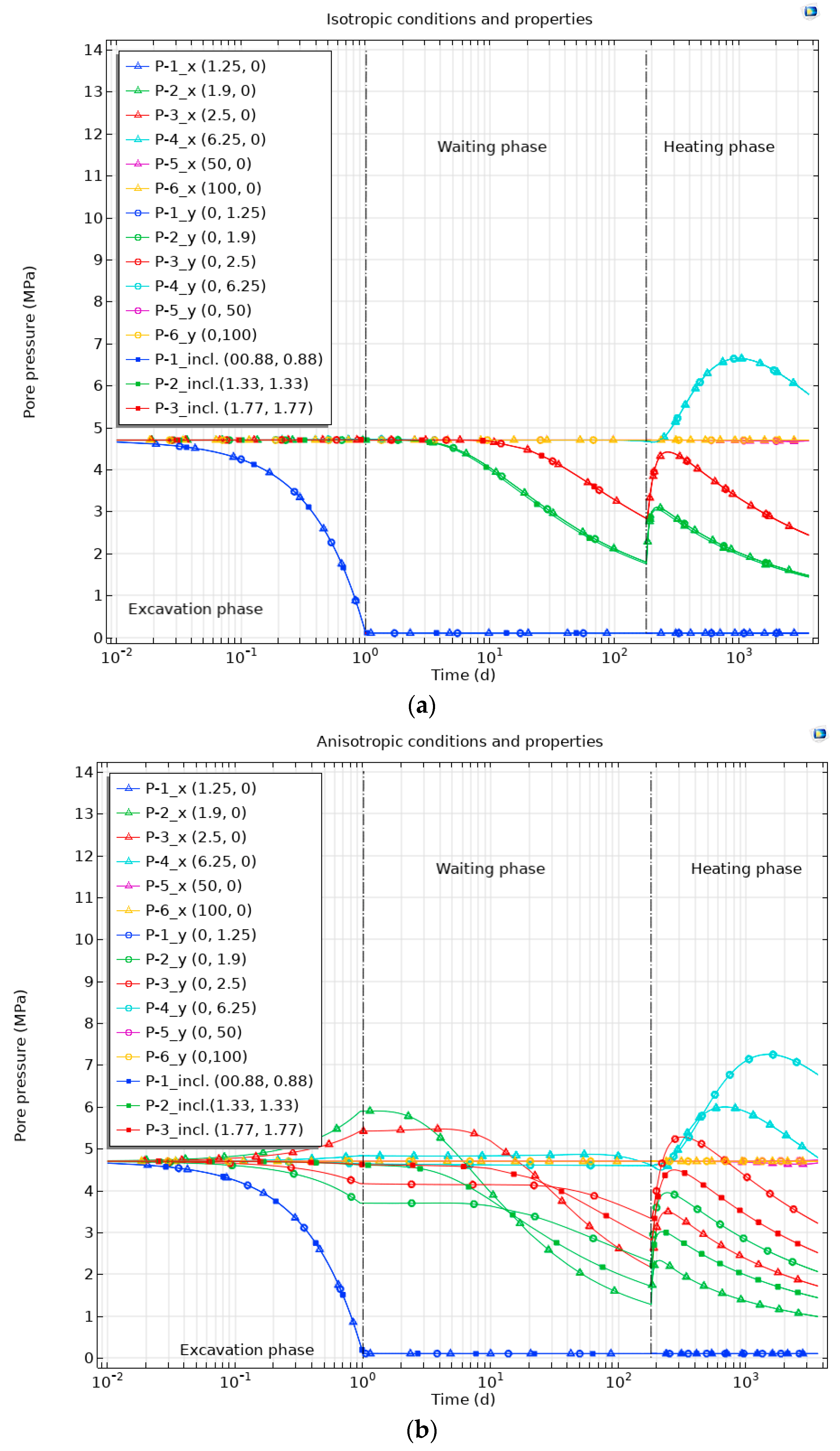
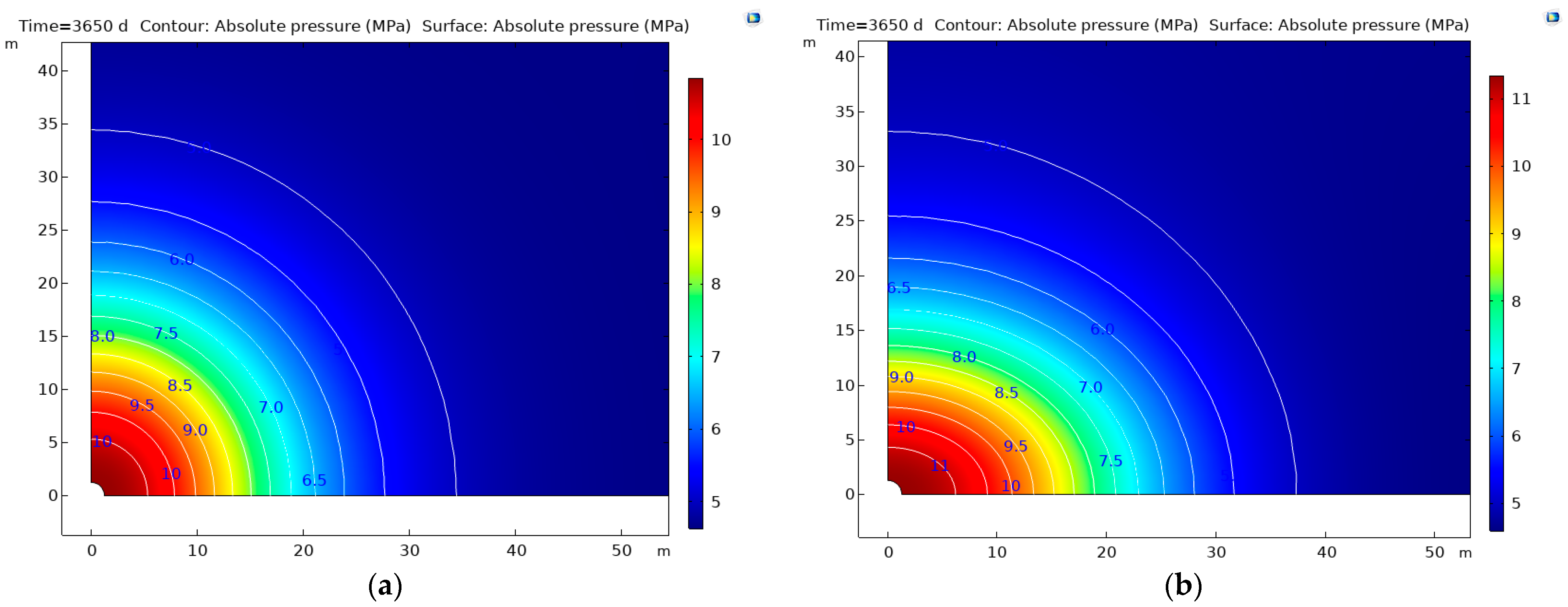
3.1.2. Hydraulic Response

The distribution of the pore pressure in the modeled domain by the end of the waiting and heating phases is presented in Figure 5 and Figure 6. The Figures show the change in pore pressure. During the waiting phase, the pressure decreased to the prescribed pressure (=atmospheric pressure) (Figure 5). After that, an elevated temperature led to an increase in the pore pressure because of the heating at the boundary of the disposal tunnel. The pore pressure distribution was isotropic for isotropic stress conditions and isotropic material properties ( Figure 5a and Figure 6a).
In the case of anisotropic stress conditions and anisotropic (hydraulic, thermal, and mechanical) properties, the decrease in the pore pressure (during 0–180 days) was followed by a subsequent increase during the heating phase. However, the pore pressure distribution was not isotropic in this case (Figure 5b and Figure 6b).
The analysis of pore pressure for isotropic and anisotropic cases was continued by evaluating the maximum pressure within the overall analyzed domain from the model output. The maximum pore pressure of 4.7 MPa was observed within the modeled domain by the end of the waiting phase, while during the heating phase it was 7.3 MPa by the end of the simulation for the isotropic case. This increased pore pressure occurred within the region of 10–13 m away from the tunnel wall. For anisotropic conditions and properties, the maximum pressure predicted by the numerical simulation was higher than for the isotropic case: during the waiting phase (but not at the end of it), the anisotropy caused a pore overpressure to 6.1 MPa in the domain and 7.7 MPa during the heating phase.
The evolution of pore pressure at the main observation points and 3 auxiliary points located farther from the tunnel is presented in Figure 7.
For the system with isotropic stress conditions and isotropic THM-related properties, the heating-induced overpressure was higher than the pore pressure decrease during the waiting phase for points P-4_x and P-4_y located at 5 times the tunnel radius from the tunnel wall. At the points located closer to the tunnel, the induced pore pressure increase was lower than the one that occurred due to excavation and waiting. The heat load had no impact on the pore pressure at points located far from the heat source (at coordinates 50 m, 100 m). The maximum pore pressure was 7.2 MPa.
Meanwhile, in the case of anisotropic stress conditions and anisotropic THM-related properties, for the points located at a distance of 1.5 times R (P-2_x) and 2 times R (P-3_x), the redistribution of stresses and the reduction of pore pressure due to tunnel excavation induced an increase in pore pressure (up to 5.5–6 MPa) during the waiting phase. Later, the pore pressure induced by the heat load exceeded the initial value at points P-3_y, P-4_x, and P-4_y.
In the anisotropic case, the impact was observed at a closer point (P-3_x) but only in the horizontal direction compared to the isotropic case. In the rest of the observation points (located closer to the tunnel), the heat-induced pore pressure increase did not compensate for the decrease due to excavation and waiting.

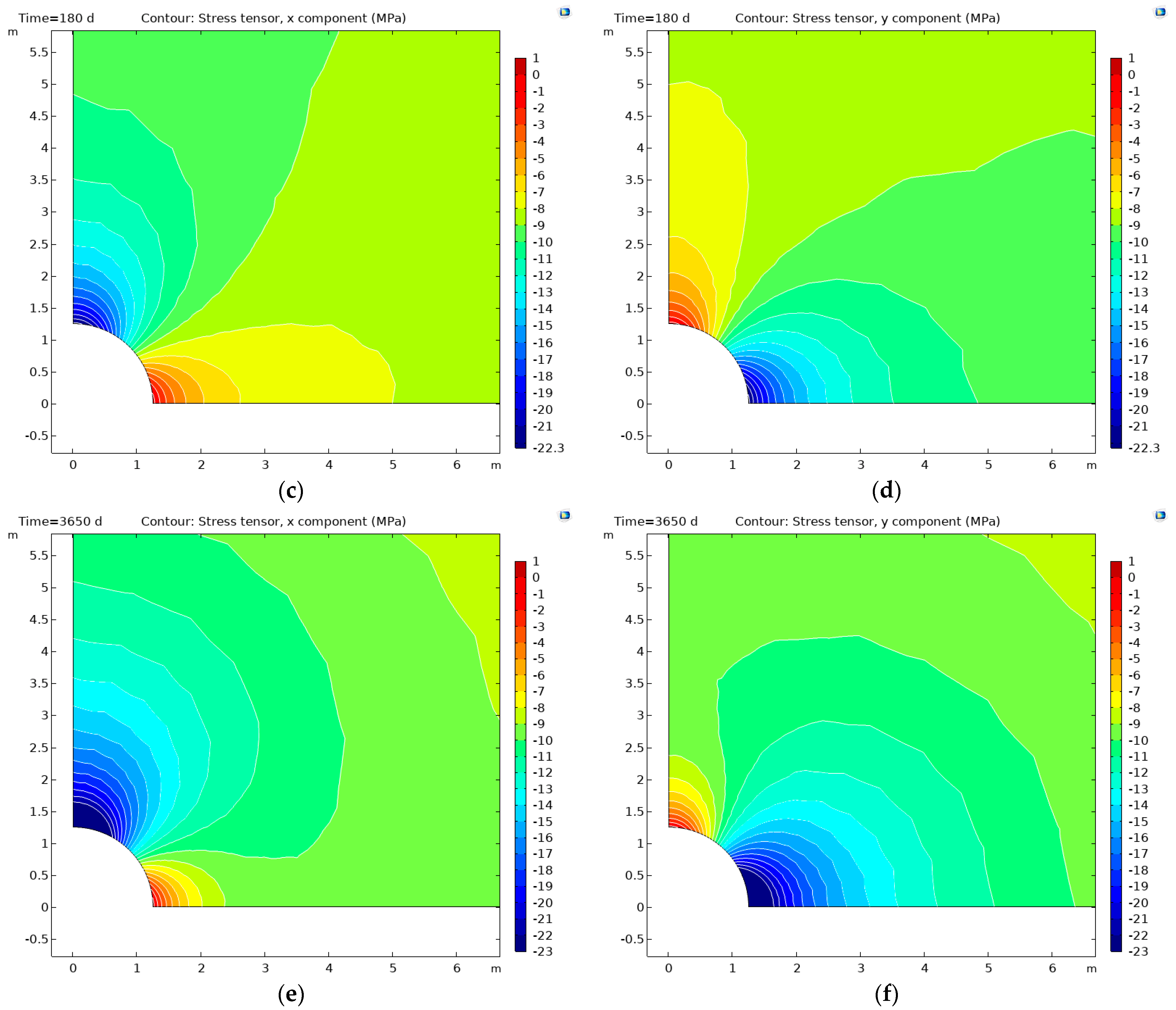
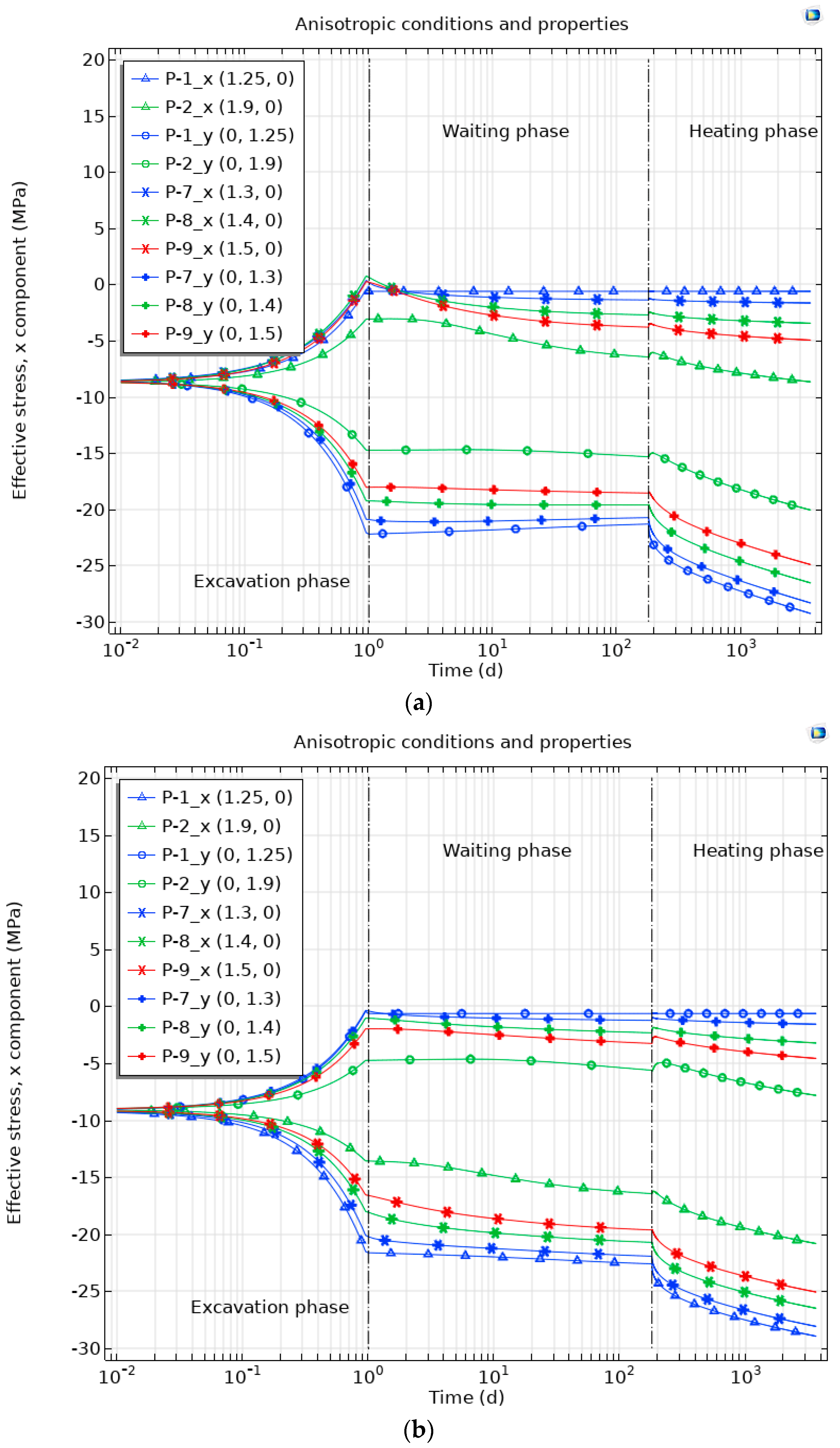
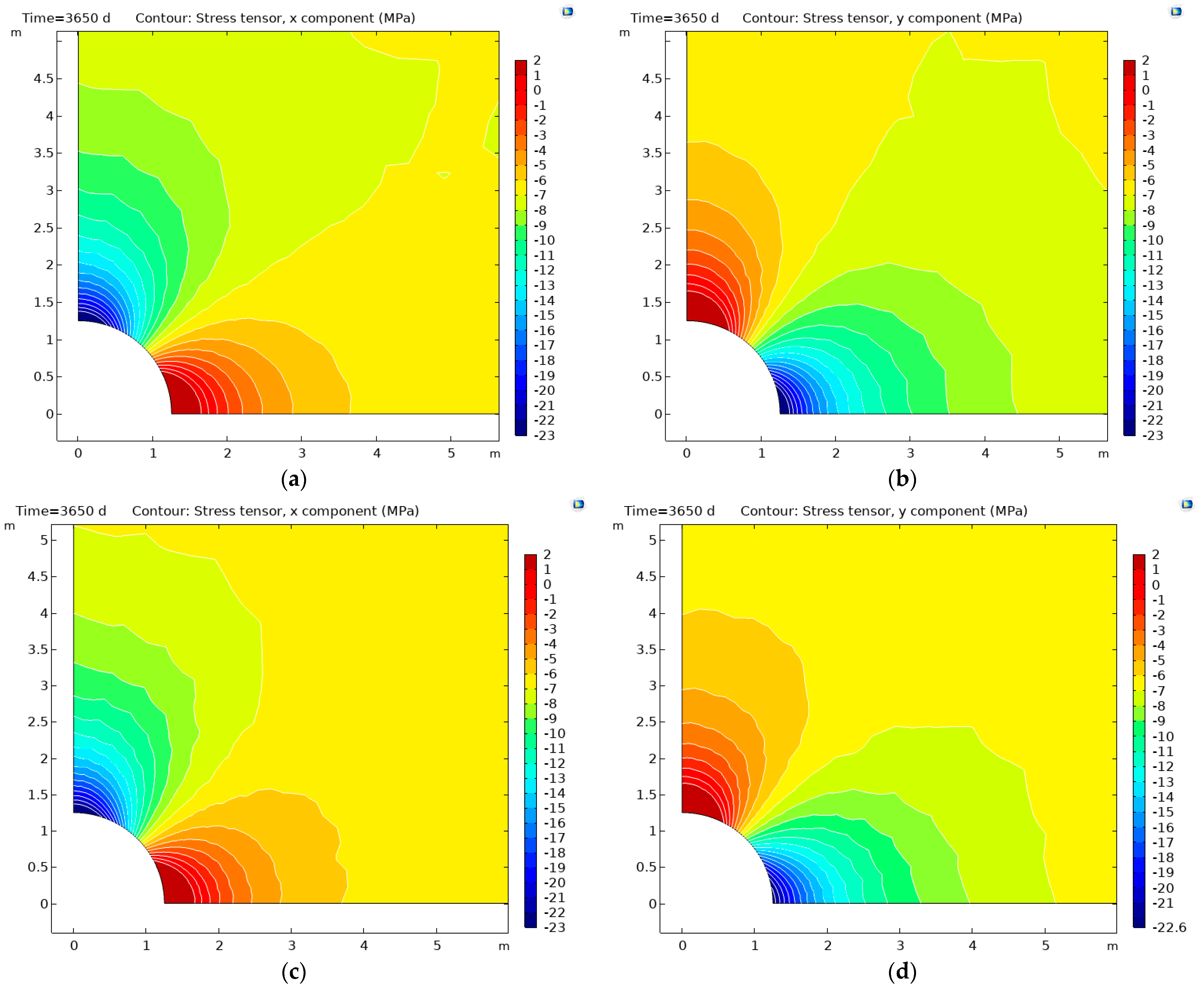
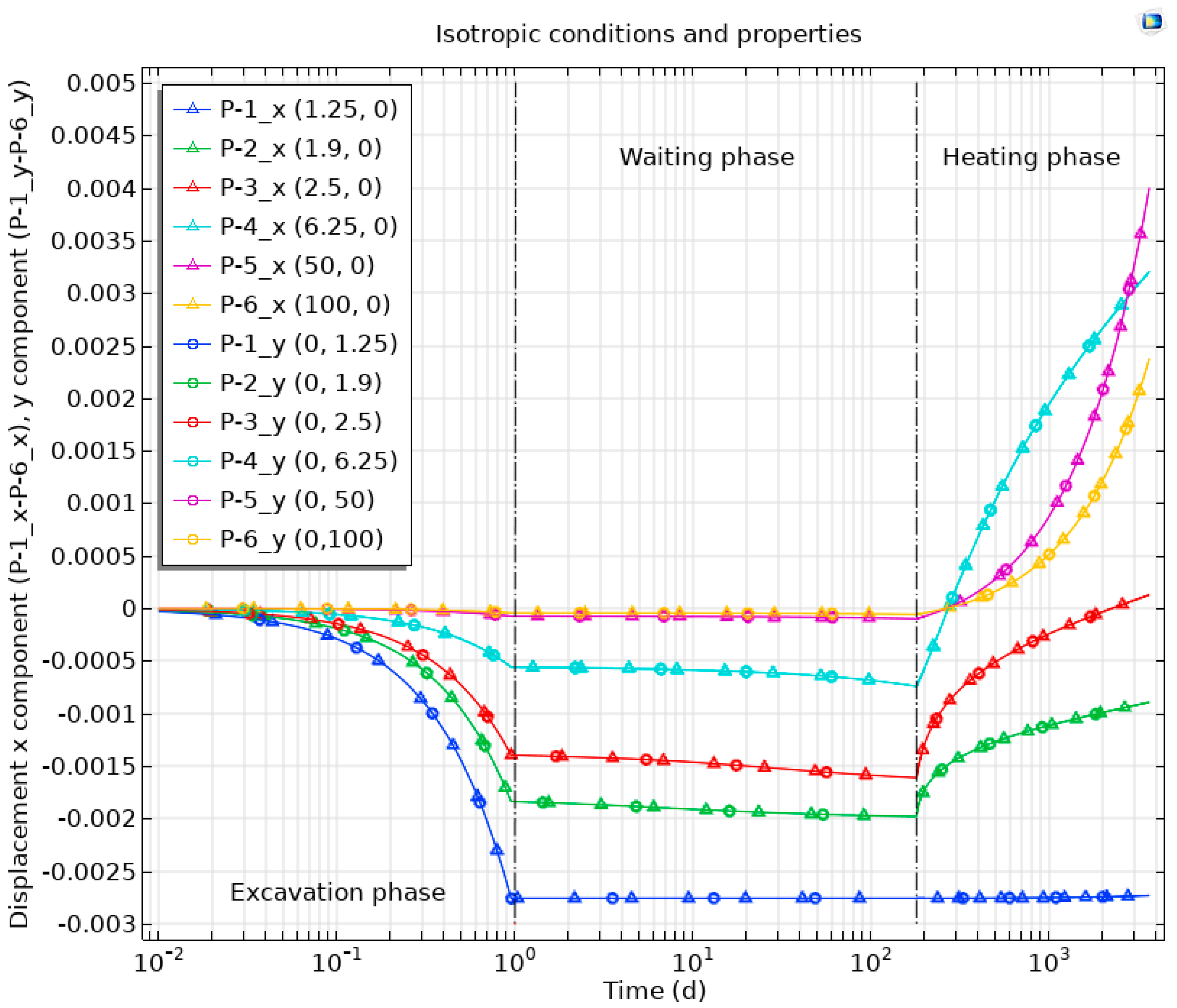
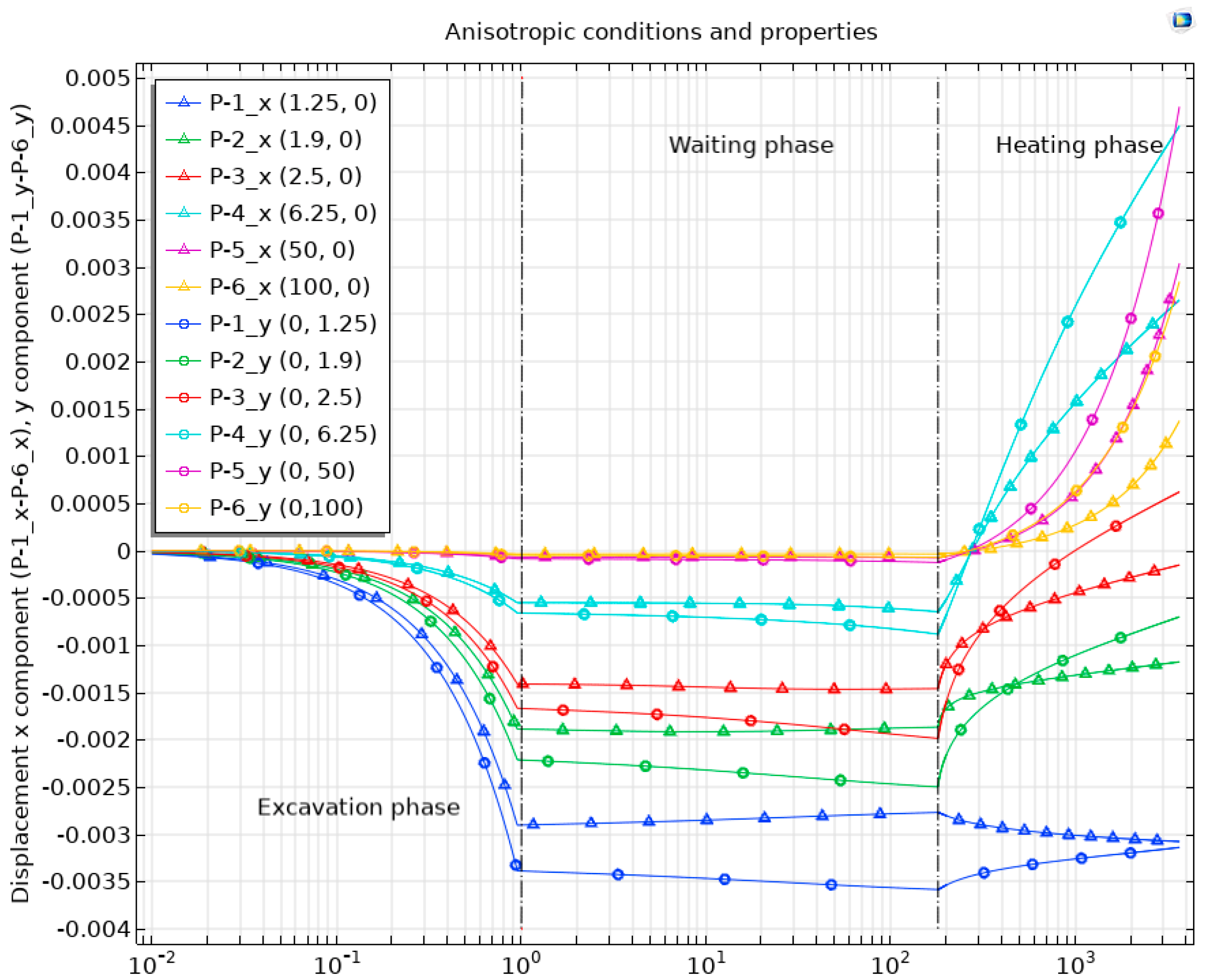
3.1.3. Mechanical Response

The heat load on a poroelastic material does not result solely in changed pore pressure. Any change in the pore pressure results in stress redistribution and affects the mechanical regime within the material. The modeling results showed that the pore pressure evolution caused stress redistribution and reduction of the effective compressive stresses (sign notation in figures: “-” stands for compressive stress). Due to the tunnel excavation process, a small zone with tensile stresses (<1 MPa) was identified in the COx at the end of 1 day (Figure 8a,b) for the isotropic case. However, the stress state changed during the waiting phase and there were no regions with tensile stresses by the end of the waiting phase (180 d) (Figure 8c,d) or the heating phase (Figure 8e,f).
A similar trend was observed for the anisotropic case. As could be seen in Figure 9, the tensile effective stress at points closer to the tunnel would occur by the end of excavation (additional observation points P-7_x–P-9_x in the horizontal direction). However, there were no regions with stress in a tensile state in the vertical direction (additional points P-7_y–P-9_y) (Figure 9b). In the isotropic case, such regions were observed in both directions (Figure 8a,b).
The redistribution of effective stress results in mechanical deformations. Our model predicted a larger displacement towards the tunnel center (due to stress release during excavation) for the observation points closer to the tunnel boundary (Figure 10, “excavation phase”). During the waiting phase, the displacement evolution was not very significant or remained at the level imposed during the excavation phase (for example, at points P-1_x and P-1_y) for the isotropic case (Figure 10a, “Waiting phase”). On the other hand, for the anisotropic case, the tunnel wall did not remain at the position imposed by the excavation phase (Figure 10b, “Waiting phase“). The displacement at point P-1_x indicated the movement of the tunnel wall toward the outward direction from the tunnel, while the point on the tunnel top (P-1_y) moved toward the tunnel center during the waiting phase (Figure 10b). This confirms the impact of the anisotropy in stress and properties on the mechanical behavior of the material.
During the heating phase, the heat-induced thermal expansion and the redistribution of the effective stress add their contribution to the overall deformations. Depending on the stress conditions and properties (isotropic vs. anisotropic), the overall effect was different. The points on the tunnel wall remained more or less at the same positions for the isotropic case (Figure 10a), while for the anisotropic case, a slight movement toward/outward the tunnel center was predicted (Figure 10b). For the observation points located closer to the tunnel (within a distance less than 5 times R), the displacements were larger for the anisotropic case compared to the isotropic case. The impact on the displacements at points located farther from the disposal tunnel (50, 100 m away) was likely to be the opposite: larger displacements were for isotropic conditions. From the perspective of the displacements, the impact of anisotropy was not unambiguous.

3.2. Heating under Undrained Conditions

The following sections present the results of the assessment of heat load impact on the COx clay rock thermal state and the THM response when the heating occurs with undrained conditions at the tunnel boundary. We compared our modeling results to the results obtained for the heating under drained conditions.

3.2.1. Thermal State

The modeling results showed that for heating under undrained conditions, the trend of induced temperature distribution around the disposal tunnel is similar to that observed for heating under drained conditions (Figure 4). The highest temperature was observed at the tunnel wall and did not exceed 76 °C in the case of isotropic stress conditions and with isotropic material properties (Figure 4a). The anisotropy in stress conditions and material properties led to higher temperature values at the observation points. For heating under undrained conditions, the maximum temperature at the tunnel boundary was also observed to be higher by ~4 °C compared to the isotropic case. The difference in temperature between the observation points on the tunnel wall was less than 0.003%. The overall temperature distribution in the claystone was anisotropic (Figure 11).
The comparison of the temperature at the observation points for both variants (DC and UDC) showed that the temperature was in principle the same as the values for isotropic and anisotropic cases. Therefore, different water drainage conditions had no impact on the thermal state around the disposal tunnel.

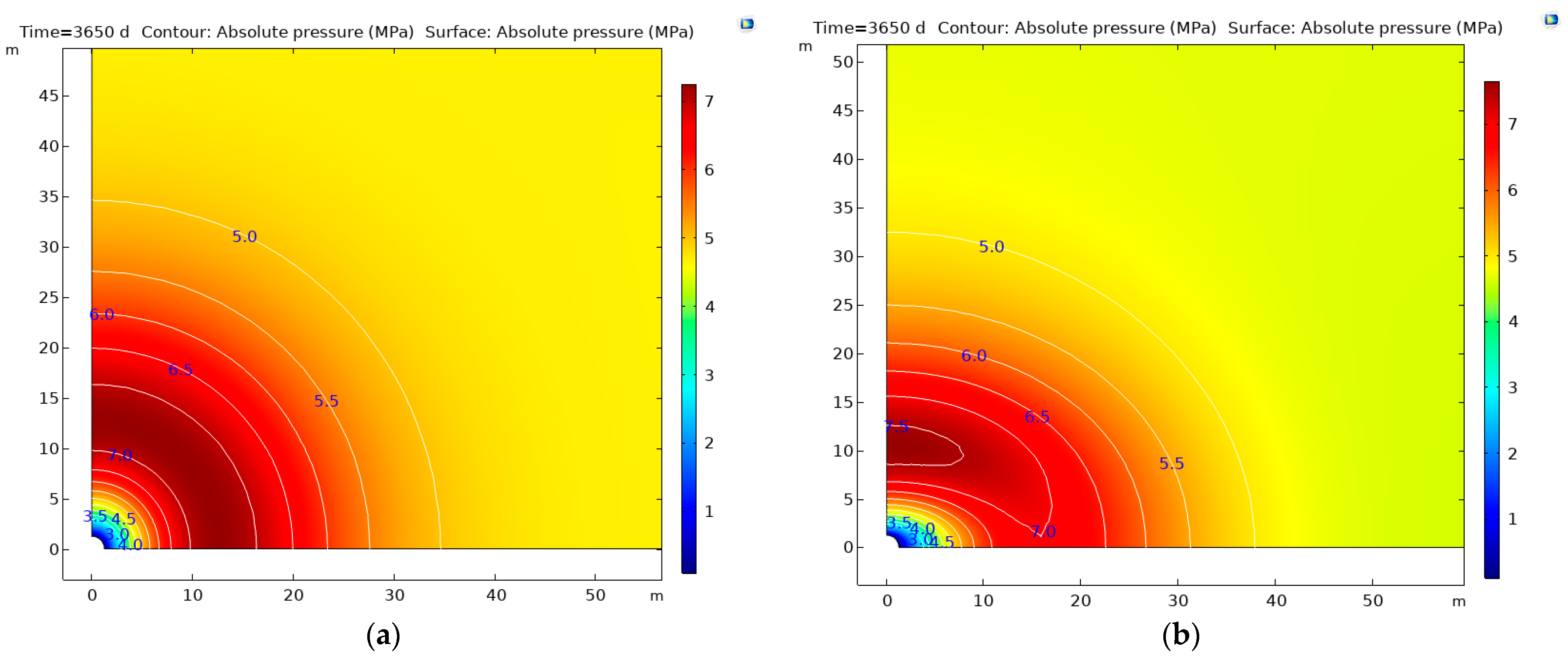
3.2.2. Hydraulic Response

The distribution of the pore pressure by the end of the waiting phase for undrained conditions (UDC variant) was the same as for the case of heating under drained conditions (Figure 6a,b). The pore pressure distribution after 10 years of heating under undrained conditions is presented in Figure 12.
As it is presented in Figure 12, the heat-induced change in pore pressure was significant. As was expected, the pore pressure distribution was isotropic for isotropic stress conditions and isotropic material properties. We also observed the pore pressure decrease (during 0–180 days) and a subsequent increase during the heating phase in the case of anisotropic stress conditions and anisotropic (hydraulic, thermal, mechanical) properties. However, the pore pressure distribution was not isotropic in this case (Figure 12b).
Figure 13 shows the pore pressure evolution at the main observation points (P-1–P-6) and 3 auxiliary points (P-1–P-3). The pore pressure evolution during the excavation and waiting phases are analogs to the DC case because no heating takes place during these phases. Heating under undrained conditions on the tunnel boundary led to a larger increase in pore pressure. For the points closer to the tunnel boundary (e. g. P-1_x–P-3_x, P-1_y–P-3_y), it increased from 4.7 MPa (in-situ pressure) up to 10.8 MPa by the end of 10 years for the isotropic case (Figure 13a). For the anisotropic case, the maximum pore pressure there was higher by ~ 0.5 MPa (Figure 13b).
The increase in pore pressure was more significant under undrained conditions than under drained conditions, i.e., by ~3.6 MPa (isotropic case) and by ~3.7 MPa (anisotropic case). Thus, as well as anisotropy, the hydraulic condition on the tunnel boundary is likely to have a significant impact on the hydraulic response.

3.2.3. Mechanical Response

Our simulation results (Figure 14) showed the reduction of the effective compressive stresses. The modeled domain remained in the compressive state except for the region less than 1.5 R away from the tunnel where tensile stresses occurred. The regions in COx claystone with the tensile stress state were predicted for the isotropic case as well for anisotropic conditions and properties. Under the tensile state, new tensile fractures in the rock might be initiated or existing fractures could be opened. Subsequently, the material permeability could be enhanced. If such undrained conditions are expected in a repository and the heat load is of similar magnitude, the conditions for tensile fracture development in the rock should be investigated further. While interpreting in-situ experiment results via simulations, one should pay attention to the proper representation of real hydraulic conditions in the numerical model.
The mechanical state was different from that obtained for drained conditions (DC variant). As it has been mentioned in Section 3.1.3, the entire modeled domain (COx claystone) was in a compressive state by the end of the heating phase under drained conditions. This confirms the importance of the hydraulic condition at the tunnel boundary on the overall behavior of the clay rock in the vicinity of an HLW disposal tunnel.
Different stress conditions and anisotropic material properties had an impact on different final displacements at selected points P-1_x–P-6_x, as it is shown in Figure 15. For the points located farther from the tunnel, the trends were similar but the final displacements (by the end of the heating phase) differed for isotropic (Figure 15) and anisotropic cases (Figure 16). Similarly, as in the DC variant, the displacements at points closer to the tunnel (<5 R) were larger for the anisotropic case, while at points located farther, the displacements were larger for isotropic conditions and properties. Thus, the hydraulic condition (drained vs. undrained) had no effect on this trend but had an impact on the magnitude of the displacement.
The results in Figure 15 also show that displacements at horizontally and vertically located observation points are equal, as was expected, for the isotropic case. However, the comparison of the displacements in the vertical and horizontal directions at the points on the top and right side of the tunnel wall showed different behavior for the anisotropic case (Figure 16). During excavation, the point on the tunnel top (P-1_y) moved more (−3.38 mm) towards the tunnel center compared to the point located on the tunnel side (P-1_x) (−2.90 mm). Later, during the waiting phase, horizontal point P-1_x moved in the outward direction (−2.77 mm), but vertical point P-1_y moved toward the tunnel center (−3.58 mm). During the heating phase, the points were moved in the opposite direction, respectively. The points located farther from the tunnel moved in the outward direction during heating.
The minimal and maximal values in the overall modeled domain were derived from the numerical model output and are summarised in Table 5 for the analyzed cases.
As it has been mentioned above, the anisotropy in stress and properties had an impact on the hydro-mechanical response of the material even during the excavation and waiting phases. It also affected the thermal state of COx in the vicinity of the HLW tunnel and led to a temperature at the tunnel boundary higher by 4 °C (Table 5). The impact of anisotropy during the heating phase was quantified as resulting in higher maximal pore pressure by ~0.4–0.5 MPa.
The hydraulic condition on the tunnel boundary had no effect on the thermal state around the tunnel, but it had a significant impact on the hydro-mechanical response. Under undrained conditions, the model predicted a much higher pore pressure (by ~4.6–4.7 MPa). Increased pore pressure also contributed to the change in the stress state. Under undrained conditions, regions in COx with a potentially tensile stress state were observed. Such observations should be further investigated from the perspective of possible material tensile failure.
The mechanical state during heating under undrained conditions was different from that obtained for water drainage conditions. Under draining conditions, the entire modeled domain remained in the compressive state by the end of the heating phase. Meanwhile, for the case with the undrained tunnel wall, the modeled domain remained in the compressive state except for the region less than 1.5 R away from the tunnel where tensile stresses had occurred. The regions with the tensile stress state were predicted for the isotropic case as well for anisotropic conditions and properties. This confirms the effect and importance of water drainage on the overall behavior of the clay rock in the vicinity of the HLW disposal tunnel.
Different stress conditions and anisotropic material properties had an impact on different final displacements in the analyzed points. Also, because of anisotropy, the tunnel wall did not remain at the same position as reached after excavation. From the perspective of displacements, the impact of anisotropy was not unambiguous. For the observation points located closer to the tunnel (within the distance of 5 times the tunnel radius R), final displacements were larger for the anisotropic case than those observed for the isotropic case. The impact on displacements at points located farther from the disposal tunnel (50, 100 m away) was likely to be the opposite: larger displacements were for isotropic conditions. This trend was observed for both tested water drainage conditions. However, the magnitude of final displacements in the analyzed points differed for drained vs. undrained conditions. In summary, the hydraulic condition on the tunnel wall had no effect on the mentioned trend in the case of anisotropy but had an impact on the magnitude of displacement.

4. Conclusions

A numerical model for THM processes was developed in COMSOL Multiphysics (Burlington, USA), in the framework of the European joint program EURAD. The model was based on the assumptions of poroelasticity. This model’s formulation was applied to analyze the behavior of the COx clay host rock under different stress conditions, anisotropic THM-related properties, and different water drainage conditions (hydraulic conditions) at the tunnel boundary. After the analysis of the obtained modeling results, the following conclusions can be drawn:
  • The anisotropy in stress and properties had an impact on the hydro-mechanical response of the material even during the excavation and waiting phases.
  • Because of anisotropy, the temperature at the tunnel boundary was higher by 4 degrees of Celsius.
  • The water drainage condition on the tunnel boundary had no effect on the thermal state around the tunnel; however, it had a significant impact on the hydro-mechanical response.
  • For heating under undrained conditions, the regions with the tensile stress state were predicted for the isotropic case as well for anisotropic conditions and properties. The potential for the regions with the tensile stress state was observed near the tunnel wall, but not 1.5 times the tunnel radius away.
  • If undrained conditions will prevail in the repository and the heat load will be of a similar magnitude, the tensile fracture development conditions should be investigated further.
  • As for the interpretation of in-situ experimental results via simulations, attention should be paid to the proper representation of real hydraulic conditions in the future numerical model.
  • The present modeling results will serve for further investigation into the COx clay behavior under elevated temperature conditions.

Author Contributions

Investigation, A.N. and G.P.; writing—original draft preparation, A.N.; visualization, A.N.; writing—review and editing, D.J. and R.K. All authors have read and agreed to the published version of the manuscript.

Funding

EURAD program has received funding from the European union’s Horizon 2020 research and innovation program under grant agreement n°847593), as well as the Lithuanian State budget.

Data Availability Statement

Data are available from the authors upon reasonable request.

Conflicts of Interest

The authors declare no conflict of interest. The funders had no role in the design of the study; in the collection, analyses, or interpretation of data; in the writing of the manuscript, or in the decision to publish the results.

References

  1. Licence Granted for Finnish Used Fuel Repository. 2015. Available online: https://www.world-nuclear-news.org/WR-Licence-granted-for-Finnish-used-fuel-repository-1211155.html (accessed on 1 June 2022).
  2. Posiva Submits Application for Operating Licence for Encapsulation and Final Disposal Facility of Spent Nuclear Fuel. 2021. Available online: https://www.posivasolutions.com/news/pressreleasesstockexchangereleases/2021/posivasubmitsapplicationforoperatinglicenceforencapsulationandfinaldisposalfacilityofspentnuclearfuel.html (accessed on 1 June 2022).
  3. Swedish Government Approves SKB’s Final Repository System. Available online: https://www.neimagazine.com/news/newsswedish-government-approves-skbs-final-repository-system-9448895 (accessed on 2 June 2022).
  4. Vu, M.-N.; Armand, G.; Plua, C. Thermal Pressurization Coefficient of Anisotropic Elastic Porous Media. Rock Mech. Rock Eng. 2020, 53, 2027–2031. [Google Scholar] [CrossRef]
  5. Guo, R.; Thatcher, K.; Seyedi, D.; Plúa, C. Calibration of the thermo-hydro-mechanical parameters of the Callovo-Oxfordian claystone and the modelling of the ALC experiment. Int. J. Rock Mech. Min. Sci. 2020, 132, 104351. [Google Scholar] [CrossRef]
  6. Armand, G.; Bumbieler, F.; Conil, N.; de La Vaissière Bosgiraud, J.M.; Vu, M.N. Main outcomes from in situ THM experiments programme to demonstrate feasibility of radioactive HL-ILW disposal in the Callovo–Oxfordian claystone. J. Rock Mech. Geotech. Eng. 2017, 9, 415–427. [Google Scholar] [CrossRef]
  7. Braun, P.; Ghabezloo, S.; Delage, P.; Sulem, J.; Conil, N. Transversely Isotropic Poroelastic Behaviour of the Callovo-Oxfordian Claystone: A Set of Stress-Dependent Parameters. Rock Mech. Rock Eng. 2021, 54, 377–396. [Google Scholar] [CrossRef]
  8. Armand, G.; Conil, N.; Talandier, J.; Seyedi, D. Fundamental aspects of the hydromechanical behaviour of Callovo-Oxfordian claystone: From experimental studies to model calibration and validation. Comput. Geotech. 2017, 85, 277–286. [Google Scholar] [CrossRef]
  9. Braun, P.; Delage, P.; Ghabezloo, S.; Baptiste, C.; Conil, N.; Vu, M. Inducing Tensile Failure of Claystone Through Thermal Pressurization in a Novel Triaxial Device. Rock Mech. Rock Eng. 2022, 55, 3881–3899. [Google Scholar] [CrossRef]
  10. Vu, M.; Souley, M.; Alonso, M.; Vaunat, J.; Gens, A.; Plúa, C.; De Lesquen, C.; Armand, G. Creep Effects on the Thermo-Hydro-Mechanical Responses of Callovo-Oxfordian Claystone. In Challenges and Innovations in Geomechanics; Barla, M., Di Donna, A., Sterpi, D., Eds.; Springer: Cham, Switzerland, 2021; Volume 125. [Google Scholar] [CrossRef]
  11. De Lesquen, C.; Vu, M.N.; Simo, E.; Besuelle, P.; Raude, S.; Dizier, A.; Narkuniene, A.; Reinicke, A.; Collin, F.; Gens, A. Final modelling report on effect of temperature on near field properties. 2020. Second version as of 02.07.2021 of deliverable D7.6 of the HORIZON 2020 project EURAD. EC Grant agreement no: 847593.
  12. Thatcher, K.; Bond, A.; Norris, S. Pore pressure response to disposal of heat generating radioactive waste in a low permeability host rock. Int. J. Rock Mech. Min. Sci. 2020, 135, 104456. [Google Scholar] [CrossRef]
  13. Xu, H.; Rutqvist, J.; Plúa, C.; Armand, G.; Birkholzer, J. Modeling of thermal pressurization in tight claystone using sequential THM coupling: Benchmarking and validation against in-situ heating experiments in COx claystone. Tunn. Undergr. Space Technol. 2020, 103, 103428. [Google Scholar] [CrossRef]
  14. Seyedi, D.; Plúa, C.; Vitel, M.; Armand, G.; Rutqvist, J.; Birkholzer, J.; Xu, H.; Guo, R.; Thatcher, K.; Bond, A.; et al. Upscaling THM modeling from small-scale to full-scale in-situ experiments in the Callovo-Oxfordian claystone. Int. J. Rock Mech. Min. Sci. 2021, 144, 104582. [Google Scholar] [CrossRef]
  15. Garitte, B.; Nguyen, T.S.; Barnichon, J.; Graupner, B.; Lee, C.; Maekawa, K.; Manepally, C.; Ofoegbu, G.; Dasgupta, B.; Fedors, R.; et al. Modelling the Mont Terri HE-D experiment for the Thermal–Hydraulic–Mechanical response of a bedded argillaceous formation to heating. Environ. Earth Sci. 2017, 76, 345. [Google Scholar] [CrossRef]
  16. Wang, W.; Shao, H.; Nagel, T.; Kolditz, O. Analysis of coupled thermal-hydro-mechanical processes during small scale in situ heater experiment in Callovo-Oxfordian clay rock introducing a failure-index permeability model. Int. J. Rock Mech. Min. Sci. 2021, 142, 104683. [Google Scholar] [CrossRef]
  17. Bumbieler, F.; Plúa, C.; Tourchi, S.; Vu, M.; Vaunat, J.; Gens, A.; Armand, G. Feasibility of constructing a full-scale radioactive high-level waste disposal cell and characterization of its thermo-hydro-mechanical behavior. Int. J. Rock Mech. Min. Sci. 2021, 137, 104555. [Google Scholar] [CrossRef]
  18. Conil, N.; Vitel, M.; Plúa, C.; Vu, M.; Seyedi, D.; Armand, G. In Situ Investigation of the THM Behavior of the Callovo-Oxfordian Claystone. Rock Mech. Rock Eng. 2020, 53, 2747–2769. [Google Scholar] [CrossRef]
  19. Tourchi, S.; Vaunat, J.; Gens, A.; Bumbieler, F.; Vu, M.; Armand, G. A full-scale in situ heating test in Callovo-Oxfordian claystone: Observations, analysis and interpretation. Comput. Geotech. 2021, 133, 104045. [Google Scholar] [CrossRef]
  20. Wang, W.; Shao, H.; Rink, K.; Fischer, T.; Kolditz, O.; Nagel, T. Analysis of coupled thermal-hydro-mechanical processes in Callovo-Oxfordian clay rock: From full-scale experiments to the repository scale. Eng. Geol. 2021, 293, 106265. [Google Scholar] [CrossRef]
  21. Yuan, Y.; Xu, T.; Gherardi, F.; Lei, H. Thermo-Hydro-Mechanical Coupled Modeling of In-Situ Behavior of the Full-Scale Heating Test in the Callovo-Oxfordian Claystone. Energies 2022, 15, 4089. [Google Scholar] [CrossRef]
  22. Seyedi, D.M.; Armand, G.; Noiret, A. “Transverse Action”—A model benchmark exercise for numerical analysis of the Callovo-Oxfordian claystone hydromechanical response to excavation operations. Comput. Geotech. 2017, 85, 287–305. [Google Scholar] [CrossRef]
  23. Xu, H.; Rutqvist, J.; Birkholzer, J. A study of thermal pressurization and potential for hydro-fracturing associated with nuclear waste disposal in argillaceous claystone. Int. J. Rock Mech. Min. Sci. 2020, 136, 104536. [Google Scholar] [CrossRef]
  24. Guo, R.; Xu, H.; Plúa, C.; Armand, G. Prediction of the thermal-hydraulic-mechanical response of a geological repository at large scale and sensitivity analyses. Int. J. Rock Mech. Min. Sci. 2020, 136, 104484. [Google Scholar] [CrossRef]
  25. Plúa, C.; Vu, M.; Armand, G.; Rutqvist, J.; Birkholzer, J.; Xu, H.; Guo, R.; Thatcher, K.; Bond, A.; Wang, W.; et al. A reliable numerical analysis for large-scale modelling of a high-level radioactive waste repository in the Callovo-Oxfordian claystone. Int. J. Rock Mech. Min. Sci. 2021, 140, 104574. [Google Scholar] [CrossRef]
  26. Thatcher, K.; Bond, A.; Norris, S. Assessing the hydraulic and mechanical impacts of heat generating radioactive waste at the whole repository scale. Int. J. Rock Mech. Min. Sci. 2021, 138, 104576. [Google Scholar] [CrossRef]
  27. Pardoen, B.; Collin, F. Modelling the influence of strain localisation and viscosity on the behaviour of underground drifts drilled in claystone. Comput. Geotech. 2017, 85, 351–367. [Google Scholar] [CrossRef]
  28. Plúa, C.; Vu, M.; Seyedi, D.; Armand, G. Effects of inherent spatial variability of rock properties on the thermo-hydro-mechanical responses of a high-level radioactive waste repository. Int. J. Rock Mech. Min. Sci. 2021, 145, 104682. [Google Scholar] [CrossRef]
  29. Cuvilliez, S.; Djouadi, I.; Raude, S.; Fernandes, R. An elastoviscoplastic constitutive model for geomaterials: Application to hydromechanical modelling of claystone response to drift excavation. Comput. Geotech. 2017, 85, 321–340. [Google Scholar] [CrossRef]
  30. Mánica, M.; Gens, A.; Vaunat, J.; Ruiz, D.F. A time-dependent anisotropic model for argillaceous rocks. Application to an underground excavation in Callovo-Oxfordian claystone. Comput. Geotech. 2017, 85, 341–350. [Google Scholar] [CrossRef]
  31. Mánica, M.; Gens, A.; Vaunat, J.; Armand, G.; Vu, M. Numerical simulation of underground excavations in an indurated clay using non-local regularisation. Part 1: Formulation and base case. Géotechnique 2021, 1–21. [Google Scholar] [CrossRef]
  32. Yu, Z.; Shao, J.; Duveau, G.; Vu, M.; Armand, G. Numerical modeling of deformation and damage around underground excavation by phase-field method with hydromechanical coupling. Comput. Geotech. 2021, 138, 104369. [Google Scholar] [CrossRef]
  33. Zhao, J.J.; Shen, W.Q.; Shao, J.F.; Liu, Z.B.; Vu, M.N. A constitutive model for anisotropic clay-rich rocks considering micro-structural composition. Int. J. Rock Mech. Min. Sci. 2022, 151, 105029. [Google Scholar] [CrossRef]
  34. Rutqvist, J.; Börgesson, L.; Chijimatsu, M.; Kobayashi, A.; Jing, L.; Nguyen, T.S.; Noorishad, J.; Tsang, C.-F. Thermohydromechanics of partially saturated geological media: Governing equations and formulation of four finite element models. Int. J. Rock Mech. Min. Sci. 2001, 38, 105–127. [Google Scholar] [CrossRef]
  35. Villar, M.V.; Armand, G.; Conil, N.; de Lesquen, C.; Herold, P.; Simo, E.; Mayor, J.C.; Dizier, A.; Li, X.; Chen, G.; et al. D7.1 HITEC. Initial State-of-the-Art on THM Behaviour of (i) Buffer Clay Materials and of (ii) Host Clay Materials. Deliverable D7.1 HITEC. EURAD Project, Horizon 2020 No 847593. p. 214. Available online: https://www.ejp-eurad.eu/publications/eurad-d71-initial-sota-thm-behaviour-i-buffer-clay-materials-and-ii-host-clay (accessed on 1 June 2022).
Figure 1. Model geometry (adapted from [11]).
Minerals 12 01187 g001
Figure 2. The computational mesh of the COMSOL Multiphysics model: (a) whole domain, (b) finer discretization near tunnel boundary.
Minerals 12 01187 g002aMinerals 12 01187 g002b
Figure 3. Model domain, boundary conditions, and study points.
Minerals 12 01187 g003
Figure 4. DC variant: evolution of the temperature at points P-1 - P-6 in horizontal and vertical directions for comparison: (a) isotropic stress conditions and isotropic properties, (b) anisotropic stress conditions and anisotropic properties. Included are also the results at 3 auxiliary points located at 45 degrees from the horizontal axis. The observation point label includes point coordinates (x, y) in meters in the model domain.
Minerals 12 01187 g004aMinerals 12 01187 g004b
Figure 5. DC variant: distribution of pore pressure at the end of the waiting phase (after 180 days of simulation) (a) in the case of isotropic stress conditions and isotropic properties: (b) in the case of anisotropic stress and anisotropic properties.
Minerals 12 01187 g005
Figure 6. DC variant: distribution of pore pressure by the end of the heating phase (after 3650 days of simulation): (a) in the case of isotropic stress conditions and isotropic properties: (b) in the case of anisotropic stress and anisotropic properties).
Minerals 12 01187 g006
Figure 7. DC variant: evolution of pore pressure at selected points: (a) isotropic stress conditions and isotropic properties, (b) anisotropic stress conditions and anisotropic properties.
Minerals 12 01187 g007
Figure 8. DC variant: distribution of effective stress (x and y components) in the case of isotropic stress conditions and isotropic properties, (a,b) by the end of the excavation phase, (c,d) by the end of the waiting phase, (e,f) by the end of the heating phase.
Minerals 12 01187 g008aMinerals 12 01187 g008b
Figure 9. DC variant: evolution of the effective stress in the case of anisotropic stress conditions and anisotropic properties: (a) x component, (b) y component.
Minerals 12 01187 g009
Figure 10. DC variant: evolution of displacement x component at selected points for comparison: (a) isotropic stress conditions and isotropic properties, (b) anisotropic stress conditions and anisotropic properties.
Minerals 12 01187 g010
Figure 11. UDC variant: temperature distribution by the end of the heating phase (3650 days) (anisotropic stress conditions and anisotropic properties).
Minerals 12 01187 g011
Figure 12. UDC variant: distribution of pore pressure at the end of the heating phase: (a) in the case of isotropic stress conditions and isotropic properties: (b) in the case of anisotropic stress conditions and anisotropic properties.
Minerals 12 01187 g012
Figure 13. UDC variant: evolution of pore pressure at selected points:(a) isotropic stress conditions and isotropic properties, (b) anisotropic stress conditions and anisotropic properties.
Minerals 12 01187 g013
Figure 14. UDC variant: distribution of effective stress (x and y components) in the case of isotropic (a,b) and anisotropic (c,d) stress conditions properties by the end of the heating phase.
Minerals 12 01187 g014
Figure 15. UDC variant: evolution of displacements at selected points under the isotropic stress conditions and isotropic properties.
Minerals 12 01187 g015
Figure 16. UDC variant: evolution of displacements (x component) at selected under the anisotropic stress conditions and anisotropic properties.
Minerals 12 01187 g016
Table 1. Observation points for THM analysis (adapted from [11]).
Observation PointsCoordinates x, y, (m)Distance from Tunnel Wall (R = 1.25 m + Distance in m (Direction))
Main points
P-1_xx = 1.25, y = 0.00R + 0.00 (horiz.)
P-2_xx = 1.90, y = 0.00R + 0.65 (horiz.)
P-3_xx = 2.50, y = 0.00R + 1.25 (horiz.)
P-4_xx = 6.25, y = 0.00R + 5.00 (horiz.)
P-5_xx = 50.00, y = 0.00R + 48.75 (horiz.)
P-6_xx = 100.00, y = 0.00R + 98.75 (horiz.)
P-1_yx = 0.00, y = 1.25R + 0.00 (vert.)
P-2_yx = 0.00, 1.90)R + 0.65 (vert.)
P-3_yx = 0.00, 2.50)R + 1.25 (vert.)
P-4_yx= 0.00, y = 6.25)R + 5.00 (vert.)
P-5_yx = 0.00, y = 50.00)R + 48.75 (vert.)
P-6_yx = 0.00, y = 100.00)R + 98.75 (vert.)
Auxiliary points
P-1_incl.x = 0.88, y = 0.88)R + 0.00 (45 deg.)
P-2_incl.x = 1.33, y = 1.33)R + 0.65 (45 deg.)
P-3_incl.x = 1.77, y = 1.77)R + 1.25 (45 deg.)
P-7_xx = 1.30, y = 0.00)R + 0.05 (horiz.)
P-8_xx = 1.40, y = 0.00)R + 0.15 (horiz.)
P-9_xx = 1.50, y = 0.00)R + 1.25 (horiz.)
P-7_yx = 0.00, y = 1.30)R + 0.05 (vert.)
P-8_yx = 0.00, y = 1.40)R + 0.15 (vert.)
P-9_yx = 0.00, y = 1.50)R + 1.25 (vert.)
Table 2. In-situ stresses for analyzed cases [11].
Total Stress (MPa)Isotropic CaseAnisotropic Case
σxx12.512.4
σyy12.7
σzz16.4
Table 3. Water properties.
PropertyNotationValueUnits
Densityρw1000kg/m3
Specific heatCp,w4180J/kg/K
Compressibility at 40 °Cχw4.5 × 10−41/MPa
Volumetric thermal expansion coefficient as a function of temperature under atmospheric pressureαw∙(1 × 10⁻⁴)4 × 10⁻⁶ × T3 − 0.001 × T2 + 0.1404 × T − 0.3795, with T in °C1/°C
Water dynamic viscosity μ e A + B C + T with T in K (0 °C = 273.15 K), A = −3.719, B = 578.919, C = −137.546 (Vogel‘s formula)Pa∙s
Table 4. COx THM properties.
CasePropertyNotationValueUnits
Solid phase densityρs2690kg/m3
Bulk densityρb2450kg/m3
Porosity n0.18m3/m3
Thermal properties
Linear thermal expansion coefficientαs1.25 × 10−51/°C
Solid phase-specific heatCp,s978J/(kg∙K)
IsotropicIsotropic thermal conductivityλ1.67W/(m∙K)
AnisotropicThermal conductivity parallel to bedding λ 1.88W/(m∙K)
Thermal conductivity normal to bedding λ 1.25W/(m∙K)
Hydraulic properties
IsotropicIsotropic intrinsic permeabilityk2.3 × 10−20m2
AnisotropicIntrinsic permeability parallel to bedding k 3.9 × 10⁻²⁰m2
Intrinsic permeability normal to bedding k 1.3 × 10⁻²⁰m2
Mechanical properties
IsotropicIsotropic Young’s modulusE7000MPa
Poisson’s ratioν0.3-
AnisotropicYoung’s modulus parallel to bedding E 8000MPa
Young’s modulus normal to bedding E 5000MPa
Poisson’s ratio parallel to bedding ν 0.21-
Poisson’s ratio normal to bedding ν 0.35-
Shear modulus normal to bedding G 2500MPa
Table 5. Minimal and maximal values in the model domain.
Excavation + Waiting Phase (0–180 d)Heating Phase (Drained Conditions) (180–3560 d)Heating Phase (Undrained Conditions) (180–3560 d
TTemperature (°C)Iso.22.0:22.022.0:75.722.0:75.8
Aniso.22.0:22.022.0:79.622.0:79.6
HPore pressure (MPa)Iso.0.1:4.70.1:7.30.1:10.8
Aniso.0.1:6.10.1:7.70.1:11.4
MDisplacement (mm), isotropic casex−2.8:3.5 × 10⁻⁸−2.8:4.6−2.8:6.1
y−2.78:5.7 × 10⁻⁸−2.8:4.6−2.8:6.1
Displacement (mm), anisotropic casex−2.9:1.6 × 10⁻¹⁷−2.9:4.1−3.1:5.0
y−3.6:4.8 × 10⁻¹⁷−3.6:5.7−3.6:7.4
Effective stress (MPa), isotropic caseSx−22.3:0.4−28.9:−0.6−25.1:8.0
Sy−22.3:0.4−28.9:−0.6−25.1:8.0
Effective stress (MPa), anisotropic caseSx−22.2:0.8−29.2:−0.6−24.3:8.4
Sy−22.6:−0.4−28.9:−0.6−22.6:8.4
Publisher’s Note: MDPI stays neutral with regard to jurisdictional claims in published maps and institutional affiliations.

