Article

An Integrated Imaging Study of the Pore Structure of the Cobourg Limestone—A Potential Nuclear Waste Host Rock in Canada

1
Energy and Mineral Resources Group, RWTH Aachen University, 52064 Aachen, Germany
2
School of Energy Science and Engineering, Henan Polytechnic University, Jiaozuo 454003, China
3
School of Geosciences, China University of Petroleum (East China), Qingdao 266580, China
4
Map–Microstructure and Pores GmbH, 52064 Aachen, Germany
5
TESCAN XRE, 9052 Ghent, Belgium
6
Brenk Systemplanung GmbH, 52080 Aachen, Germany
*
Authors to whom correspondence should be addressed.
Minerals 2021, 11(10), 1042; https://doi.org/10.3390/min11101042
Submission received: 8 August 2021 / Revised: 19 September 2021 / Accepted: 23 September 2021 / Published: 26 September 2021
(This article belongs to the Topic Industrial Application of Clays and Clay Minerals)

Abstract

:
With the development of imaging technology, tools to quantitatively describe pore structure, morphology, and connectivity have been widely applied on low permeable rocks; however, it is still questionable to what extent this information can be used to predict permeability. Applicability and comparability of different techniques are discussed here for the Middle Ordovician Cobourg limestone (Canada), a rock dominated by calcite grains of variable sizes (µm–cm) and heterogeneously distributed quartz, dolomite, pyrite, and meshy clay minerals. Absolute porosities determined by helium pycnometry (HP) in literature are approximately 1.6% (±0.9%), and gas permeabilities range from 10−20 to 10−19 m2. Porosities obtained from BIB-SEM are much smaller compared to those from HP (16–69% of HP). Pores found in clays are smaller, slit-shaped, and more densely spaced when compared to those in calcite minerals. Connectivity between pores could not be resolved with 3D micro-CT or FIB-SEM reconstructions, which have a resolution limit of 8 µm and 10 nm, respectively. However, assuming the pores to be connected, laboratory-derived permeability data could be fitted using a simple capillary bundle model, including information about the visible pore size distributions obtained from BIB-SEM images and a tortuosity range of 8 to 15.

1. Introduction

In the context of the disposal of high-level radioactive waste (HLW), a broad consensus has been reached on the necessity for suitable geological formations for the safe and permanent storage of radioactive waste worldwide [1,2,3,4]. Depths between 250 and 1000 m are considered appropriate for underground mining repositories, while depths of up to 5 km are discussed for deep borehole disposal [5,6]. Potential waste disposal sites are generally located in a stable geological environment (i.e., no volcanic/seismic activity or limited uplift within 1 Ma) and contain lithological units of sufficient thickness and homogeneity, characterized by a low permeability/diffusivity as well as high self-sealing ability and radionuclide sorption capacity [6,7]. For salt and argillaceous rocks (claystones or mudstones), hydraulic isolation is generally ensured by an impermeable or low permeable matrix [3]. Highly rigid rocks such as granites and limestones, which are particularly suitable for underground construction, tend to deform brittlely, and therefore often contain a fracture network. For these rocks, long-term isolation must thus be ensured by installation of engineered barriers (containers, bentonite backfill) [5].
The Middle Ordovician Cobourg limestone, also known as the “Lindsay” limestone, is proposed as a potential host rock for deep disposal of low- and intermediate-level radioactive waste in Canada. Several investigations have been carried out so far to evaluate its mechanical properties [8,9,10,11], as well as petrological and mineralogical characteristics [12,13,14]. Since the main transport mechanism of radionuclides is via groundwater, isolation of radionuclides depends on the groundwater flow rate or interstitial velocity, which is determined by the porosity, hydraulic conductivity (or permeability), and hydraulic gradient. Porosities reported from mercury injection porosimetry (MIP), water immersion porosimetry (WIP), and helium pycnometry (HP) for the Cobourg limestone range from 0.48% to 3.03% [15,16,17]. Permeability coefficients determined with water as the permeating fluid at 5 MPa confining pressure range from 3.31 × 10⁻²³ to 1.80 × 10⁻²¹ m2 [15,18], and intrinsic gas permeabilities at the same confining pressure range from 3.15 × 10⁻²⁰ to 1.45 × 10⁻¹⁷ m2 [17]. According to Hu et al. [17], large variations in permeability coefficients can be attributed to the occurrence of stylolites. Furthermore, microscopic and macroscopic heterogeneities in the Cobourg limestone could be the cause of variations in the permeability coefficients. Day et al. [19] and Hu et al. [17] reported that the Cobourg limestone is mainly composed of a calcite phase and surrounded by a fine-grained clay mineral phase on the basis of qualitative SEM investigations. Selvadurai [10] observed on a macroscopic scale that the Cobourg limestone is composed of a light grey nodular calcite-rich phase and an inter-nodular dark grey clay-rich phase. The distribution of the latter phase shows a distinct heterogeneity, which was confirmed by Selvadurai [10] during the preparation of a large cylindrical sample (150 mm in diameter and 300 mm in length). Such a heterogeneous fabric presents a major challenge in obtaining representative elementary areas or volumes (REA or REV) for both imaging analyses and petrophysical investigations on the Cobourg limestone.
Mercury injection porosimetry (MIP) and low-pressure nitrogen or carbon dioxide adsorption are widely used to characterize the pore structure of sedimentary rocks [20,21,22]. However, these characterizations are based on simplified pore geometry assumptions. Therefore, the results lack direct information on the pore morphology and connectivity. Additionally, occurrences and distributions of pores could be linked to specific mineral phases, which cannot be investigated by fluid invasion techniques as the measurements are typically performed on the bulk rock samples [23,24,25]. X-ray micro computed tomography (micro-CT) can be used as a quantitative and non-destructive imaging technique to reconstruct the 3D microstructure from a cylindrical sample [26]. In conventional rocks such as sandstones, X-ray micro-CT was successfully used to determine an REV and to generate a 3D pore network from which simulation results on permeabilities are in good agreement with experimental measurements [27,28,29,30]. However, the resolution limitation of X-ray micro-CT becomes apparent when imaging nanoporous geomaterials. Broad ion beam milling (BIB) complements scanning electron microscopy (SEM) by enabling the preparation of millimeter-sized planar surfaces, thus providing a qualitative and quantitative approach for the characterization of the pore structure free of artifacts such as cracks or scratches on a relatively large area (several mm2) [23,31,32,33]. However, the field of observation is two-dimensional, and hence no information on the three-dimensional pore space connectivity can be obtained. Alternatively, focused ion beam milling in combination with SEM (FIB-SEM) enables the possibility of serial sectioning and simultaneous imaging. A series of high-resolution SEM images can be generated with uniform spacing, enabling 3D reconstruction and visualization of the microstructure. However, the limited volume (normally smaller than 1000 μm3) raises uncertainties about its application in quantitative analysis of heterogeneous nanoporous rocks [24,29,34,35].
Evaluation of the sealing efficiency of Cobourg limestone requires a full understanding of fluid transport processes, which is essentially based on comprehensive knowledge of the pore space at multi-scale. Due to the small pore sizes and distinct heterogeneity of the Cobourg limestone, determining an REV is challenging in terms of both mineralogy and pore space with current state-of-the-art techniques, and hence upscaling is difficult. Alternatively, selective analysis of pore morphologies and pore structures within different mineral phases of specific zones can help to improve the understanding of potential fluid transport pathways. This study aims at a detailed characterization of the pore size distribution and pore morphology down to 10 nm by utilization of FIB- and BIB-SEM techniques and provides evidence for identification of microstructures relevant for flow.

2. Samples

The Cobourg limestone investigated in this study originates from a depth of 70 m from the Saint Mary’s cement quarry in Bowmanvill, ON, Canada. The corresponding formation at the Bruce nuclear site (200 km away) is found at a depth of approximately 680 m and is being investigated as a potential host rock for disposal of low- and intermediate-level nuclear waste [10]. A benchmark study involving 28 laboratories was initiated by the McGill University to study geomechanical and fluid transport properties of the Cobourg limestone [36]. The sample utilized in this study can be characterized as a light grey nodular limestone, consisting of 79 wt.% of calcite, 9 wt.% of ankerite, 6 wt.% of clay minerals, 5 wt.% of quartz, and less than 1 wt.% of pyrite [17]. A Cobourg limestone plug (sample A) with a diameter of 25 mm and a length of 100 mm was scanned by X-ray micro-CT, and a micro-core (6 mm in diameter and 17 mm in length) was retrieved and used for high-resolution X-ray micro-CT and the subsequent BIB- and FIB-SEM imaging (Figure 1). Porosity and gas permeability measurements have been conducted on four core plugs, and the results were published in Hu et al. [17]. Porosities determined by HP ranged from 0.98% to 2.51%. For the intact samples, extrapolated helium permeability coefficients at zero effective stress ranged from 5.21 × 10⁻²⁰ to 2.74 × 10⁻¹⁹ m2. The corresponding coefficient of one other sample was 1.79 × 10⁻¹⁷ m2, which is attributed to the existence of open stylolites [17].

3. Imaging Experiments and Simulation

3.1. X-ray Micro-CT

The Cobourg limestone core was scanned on the HECTOR setup developed by the Center for X-ray Tomography at Ghent University (UGCT) and the TESCAN CoreTOM from TESCAN company. The X-ray micro-CT scanning was operated at 160 kV and resolutions of 30 and 130 µm. The micro plug was scanned at a relatively higher resolution of 8 µm (Figure 1). Details of the setup and specific operation can be found in Masschaele et al. [37] and Dierick et al. [38].

3.2. BIB-SEM

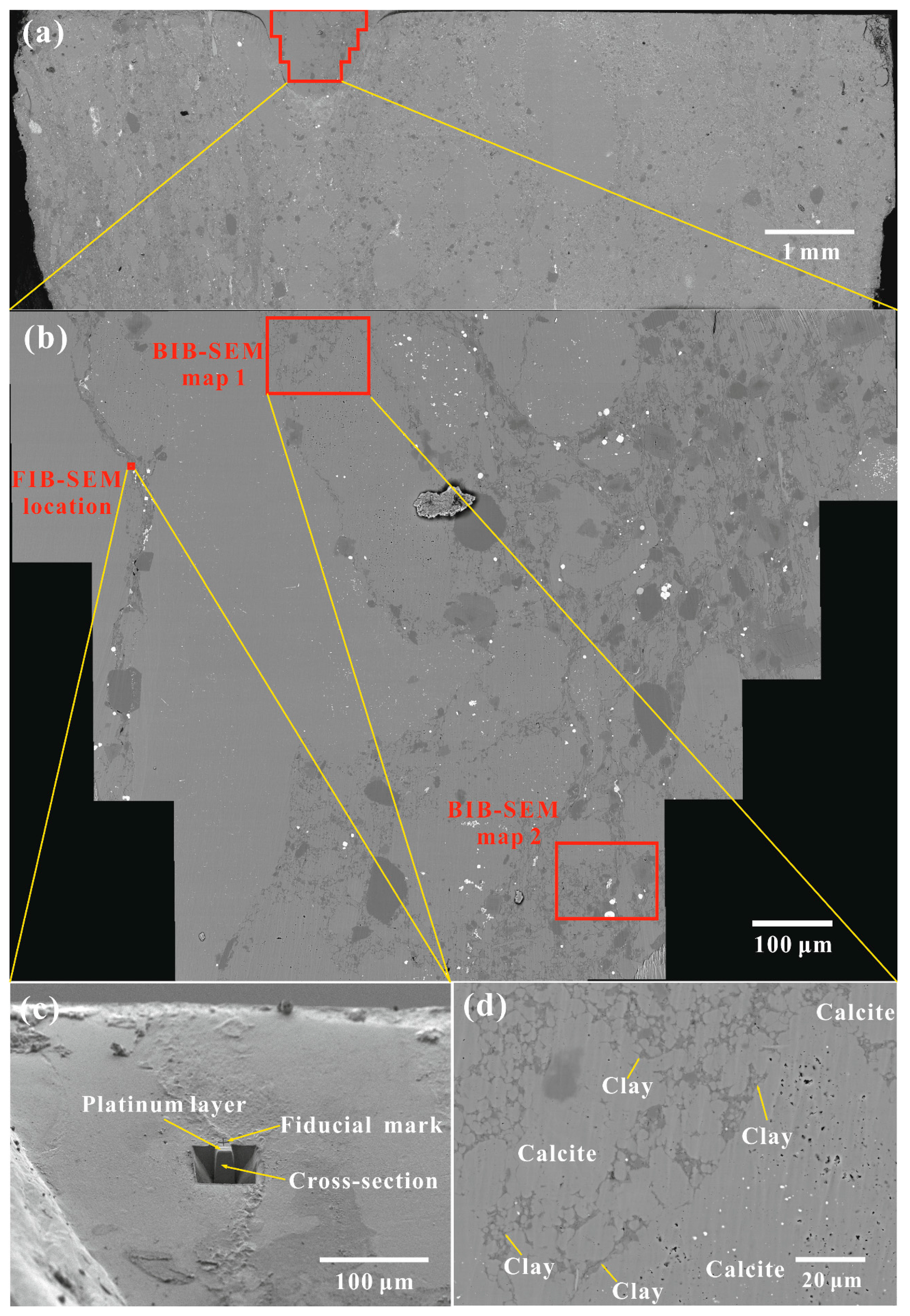
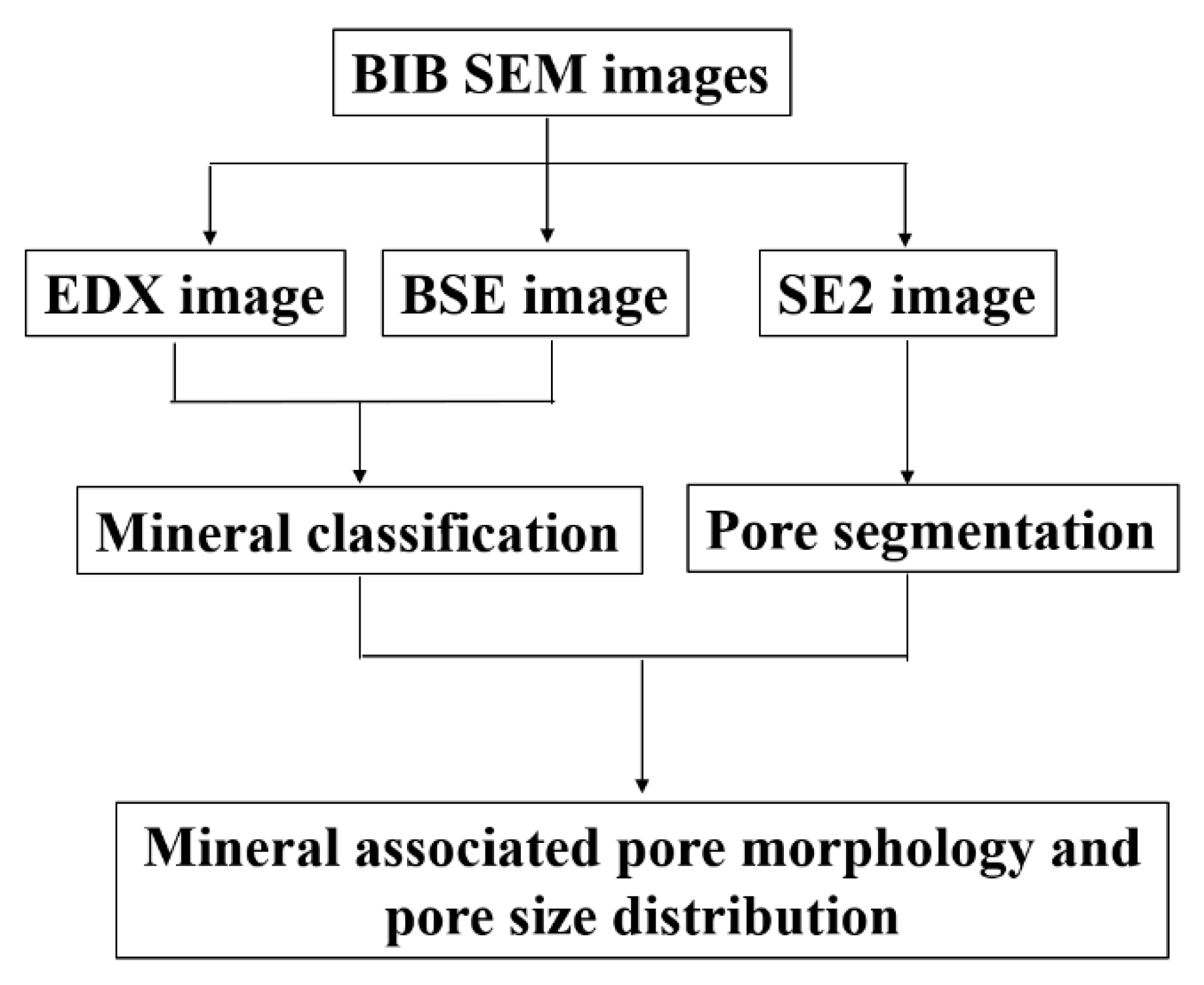
A side of the extracted micro-core was manually polished by utilization of a silicon-carbide paper (Figure 2a). In order to obtain a high-quality polished surface, a cross-section area of approximately 1 mm2 was polished at a high angle in a JEOL SM-09010 BIB cross-section polisher (JEOL, Tokyo, Japan) at 6 kV acceleration voltage for 8 h. The polished cross-section was then coated with tungsten, favorable for the subsequent imaging in a Zeiss Supra 55 SEM (ZEISS, Jena, Germany) and energy-dispersive X-ray spectroscopy (EDX) analysis (Oxford Instruments, Abingdon, UK) [23,39]. The combination of backscattered electron (BSE) images and EDX maps was used in the mineral composition analysis. High-resolution secondary electron (SE2) images were utilized for the analyses of pore morphology and pore size distribution. The classification of IUPAC for micro- (<2 nm), meso- (2–50 nm), and macropores (>50 nm) was used to describe pore size ranges [40]. Maps 1 and 2 were analyzed quantitatively for mineral composition and pore size distribution.

3.3. FIB-SEM

The region for FIB-SEM was firstly covered with a layer of platinum to decrease the occurrence probability of curtaining artifacts (Figure 2b) [24]. In the working mode of the TESCAN AMBER FIB-SEM (TESCAN, Brno, Czech Republic), the focused ion beam and electron beam intersect on the sample surface at the angle of 55°. A portion of limestone in this region was then removed by a Ga+ ion beam at accelerating voltage of 30 kV and high beam current of 20 nA, creating a prominence in a trench (Figure 2c). Thus, the first cross-sectioning could be implemented by the ion beam on an exposed wall of the prominence, and 10 nm thickness of the wall was removed to expose a fresh and polished limestone surface. For gentle slicing of the target volume, a Ga+ ion beam at accelerating voltage of 30 kV and low beam current of 250 pA was used to minimize milling artifacts. Subsequently, SEM imaging in BSE mode was conducted at a high resolution of 1107 × 1749 pixels. In this way, the ion beam cooperated with the electron beam in a repetitive milling and imaging process until the target volume was imaged. The fiducial mark was given for reference and registration of the FIB experiment (Figure 2c). A total number of 498 cross-sectional images with a voxel size of 10 nm were acquired for the reconstruction of the 3D structure.

3.4. Image Analysis

Image processing and statistical analysis of BIB-SEM images were conducted mainly in ArcMap software (version 10.5.1, Esri, Redlands, CA, USA) (Figure 3). Due to high grey level contrast between void space and solid phase in the secondary electron image, pores were automatically segmented by a built-in spatial analyst tool and the pore boundaries were automatically outlined by polygons. After the auto-segmentation, all pore boundaries were manually checked and further edited in case of segmentation errors [23]. The statistical geometrical analysis of segmented pores was focused on the morphological features including the minor axis length (W), the major axis length (L), area (A), perimeter (P), circularity (4πA/P2), and elongation (1-W/L). Based on the mineral composition obtained from X-ray diffraction (XRD) analysis [17], the mineral phases in the BSE image can be classified as calcite, dolomite, quartz, clay minerals, and pyrite by utilization of a grey level thresholding method. The corresponding EDX image was used to verify the classification. Due to the low contrast of grey level, quartz and clay minerals had to be segmented manually based on their different morphology and distribution characteristics. Finally, the segmented pores were assigned to different mineral phases by overlaying the pore layer on the mineral layer. Information about pore morphology and porosity were extracted for each mineral phase. To compare the pore size distributions in different mosaics with different sizes, the pore frequency normalized to the bin width and mosaic area was plotted against the pore area down to the practical pore resolution (PPR). When the data points fit a power law relationship, the pore size distribution can be considered as self-similar (Equations (1) and (2)) [23,32].
N i b i S m o s a i c = C · S p o r e D
l o g ( N i b i S m o s a i c ) = D · l o g ( S p o r e ) + l o g C
Here, bi is the width of bin (bi, bi+1) and bi+1 doubles bi. Ni is the frequency of pores with area (Spore) within bin (bi, bi+1). Smosaic is the total area of the mosaic map. D is the exponent of the power law relationship, and C is a constant.
The BSE images obtained from FIB-SEM were aligned by the software package Dragonfly from ORS company (Montreal, QC, Canada). The reconstructed 3D structure displays 1107 × 1749 × 498 voxels with a voxel size of 10 nm. The vertical strips (curtaining artifacts), noise, and shadowing effect of the image stack were reduced by destriping, 3D median, and 3D background correction filters, respectively. After these image processing steps, segmentation of pores can be achieved due to the high grey level contrast to surrounding minerals. The contrast of the clay minerals was challenging in the images stack, so Dragonfly’s deep learning solution was used to perform the segmentation. In this way, clay minerals were separated from calcite, and pores within clay minerals were differentiated from the pores in calcite. After the segmentation, porosity and pore size distribution were analyzed by the 3D Analysis plugin of the image J software (Fiji) (version 1.8.0, National Institutes of Health, Bethesda, MD, USA) [41].

3.5. Permeability Simulation

Permeability coefficients of the BIB-polished subsample were calculated from the statistical pore analysis based on the “ bundle of capillary tubes” model [33,42]. For a cuboid sample through which a single circular capillary tube penetrates, the volumetric flow through it can be described by Hagen–Poiseuille’s law (Equation (3)).
Q = π r 4 Δ P 8 μ l
Here, r is the radius (m) of the tube, and l denotes the tortuous length (m) of the tube. The combination of Hagen–Poiseuille’s law (Equation (3)) and Darcy’s law (Equation (4)) deduces the permeability of a single capillary tube (Equation (5)):
Q = k A μ Δ P L
Here, Q denotes the flow rate (m3/s) of permeating fluid, k represents the permeability (m2), μ is the viscosity of fluid (Pa·s), ΔP represents the pressure difference (Pa), A denotes the cross-sectional area (m2) perpendicular to the flow direction, and L is the length (m) of the sample.
k = π r 4 L 8 A l
The cross-sectional area A of the cuboid sample can be expressed as follows:
A = π r 2 l ϕ L
Here, ϕ and L are the porosity and length of the cuboid sample, respectively. By replacing the cross-sectional area A in Equation (5) with Equation (6), the permeability of a single capillary tube can be defined as:
k = ϕ r 2 8 ( l L ) 2 = ϕ r h y d 2 8 τ 2
As suggested by Philipp et al. [33], hydraulic radius (rhyd) is preferred rather than geometric radius (r), considering the prevailing irregular cross-sectional shape of pores, which is the ratio of pore area to perimeter. The ratio of the tube length (l) to the sample length (L) is defined as the tortuosity (τ), which further simplifies Equation (7).
With the 2D pore morphology information and assumed tortuosity values, the permeability coefficient of the Cobourg limestone can be estimated as the sum of individual tube permeabilities (Equation (8)).
k = ϕ r h y d 2 8 τ 2

4. Results

4.1. X-ray Micro-CT Image Analysis

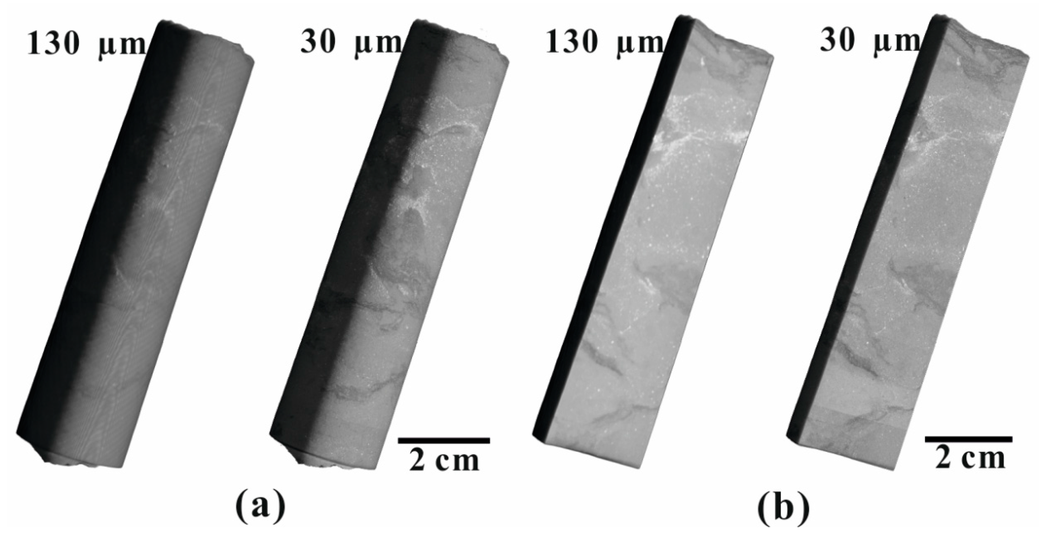
The spatial resolution of X-ray micro-CT depends on the magnification and the position of the sample between the X-ray source and detector. With the increase of the resolution from 130 μm to 30 μm, the rock compositions with different densities, displaying different grey levels in Figure 4, can be identified more clearly. However, due to the low resolution, no pores could be identified from these rock components. Figure 1 displays the rendered X-ray micro-CT image of the micro-core and gives a general overview of the mineral phases at the resolution of 8 μm. A strong heterogeneity with respect to the mineralogy is apparent. Light mineral grains of varying sizes (μm–cm) form the bulk of the rock, and dark mineral phases fill the interstice between these light grains. No pores could be segmented from these mineral phases at this resolution.

4.2. BIB-SEM Image Analysis

4.2.1. Mineralogy and Pore Morphology

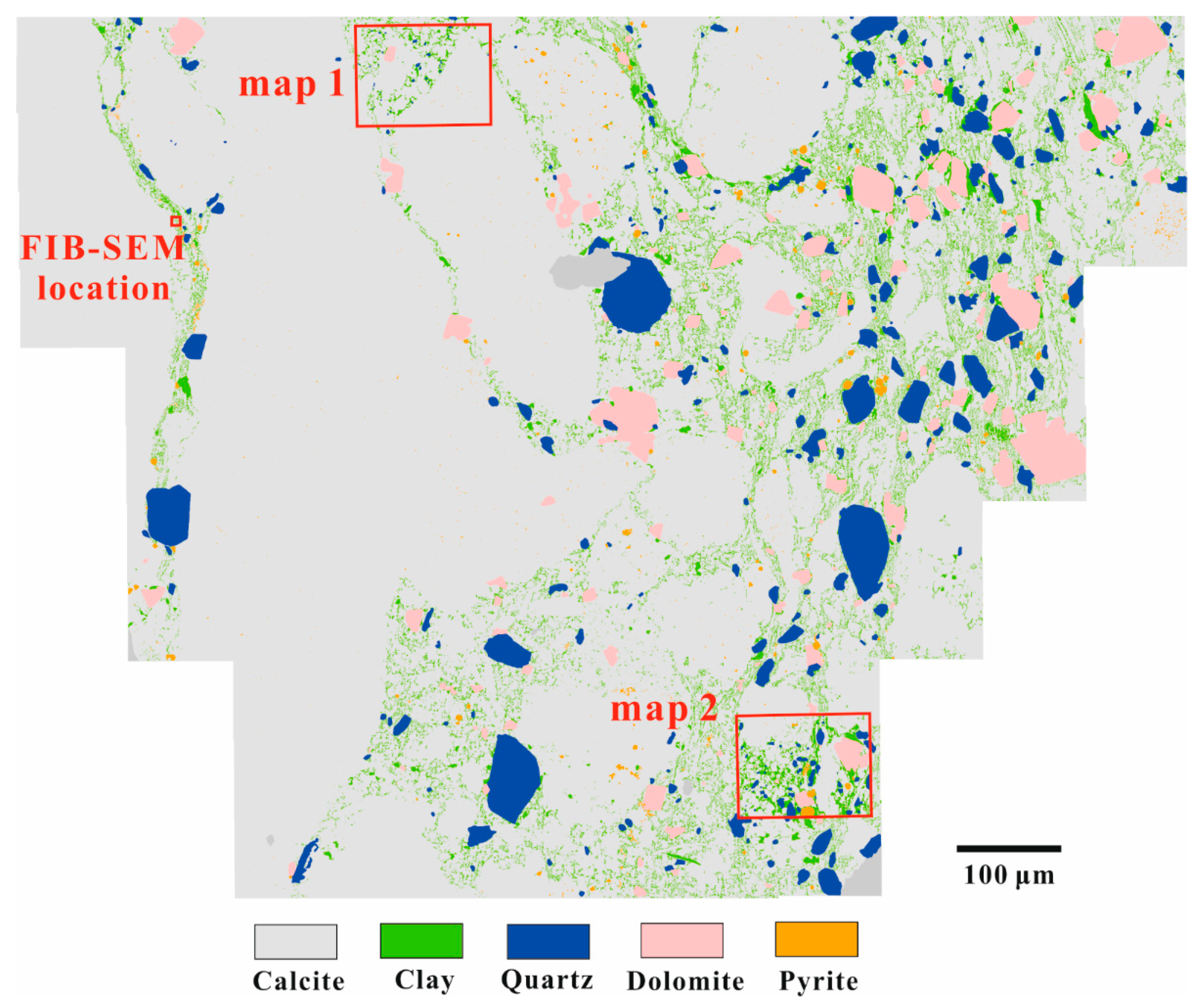
The Cobourg limestone can generally be characterized as a tight rock dominated by calcite grains of variable sizes (µm–cm) surrounded by idiomorphic or subhedral minerals (quartz, dolomite, and pyrite) and meshy clay minerals (Figure 5). Quantitative mineral area analysis of the overview map indicates that calcite is the dominant mineral phase (84.1%), followed by clay minerals (6.5%), quartz (4.6%), dolomite (4.0%), pyrite (0.4%), and other unknown minerals (0.5%) (Table 1).
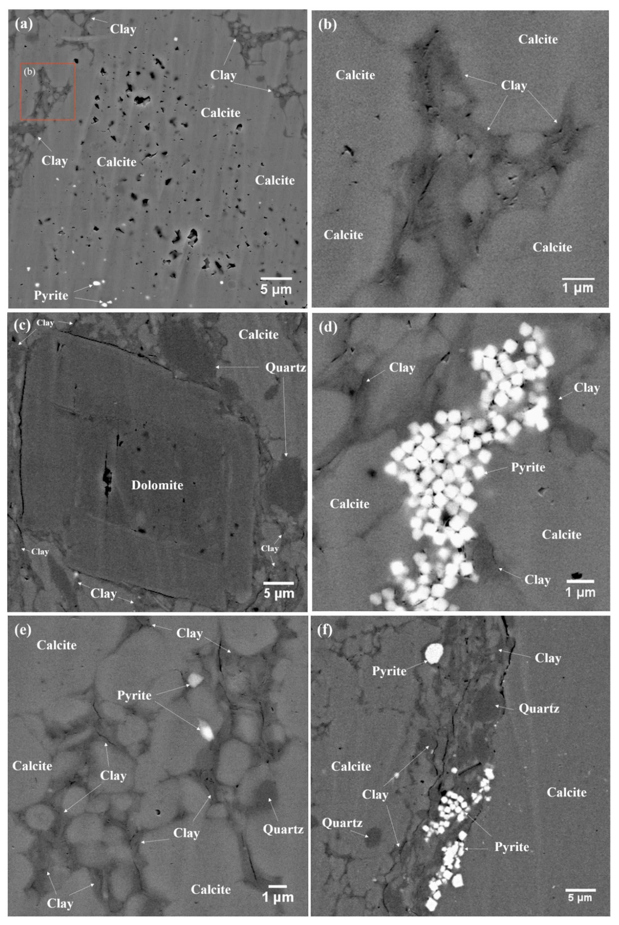
For the high-resolution maps 1 and 2, the mineral compositions deviate to different extents from the bulk rock mineral compositions due to sample heterogeneity. BIB-SEM images show that the limestone is generally quite tight, though pores can be described according to Loucks et al. [44]. Within the calcite grains, angular pores (sizes up to a few micrometer) were mostly observed (Figure 6a). Intraparticle pores also appear in rhombic dolomite (Figure 6c). Intercrystalline pores can be observed in framboidal pyrites (Figure 6d). Pores in the clay mineral fraction are relatively small compared to those in the calcite phase. They are triangular and slit-shaped, which is typical for pores in clay minerals (Figure 6b,e) [39,45]. Furthermore, microfractures also tend to appear at the interface of carbonate and clay fractions (Figure 6c,f). Considering the matching edges and sharp tips, these fractures are interpreted as artifacts caused by stress release during sampling, preparation, and drying and are therefore excluded in the porosity and pore size analyses.
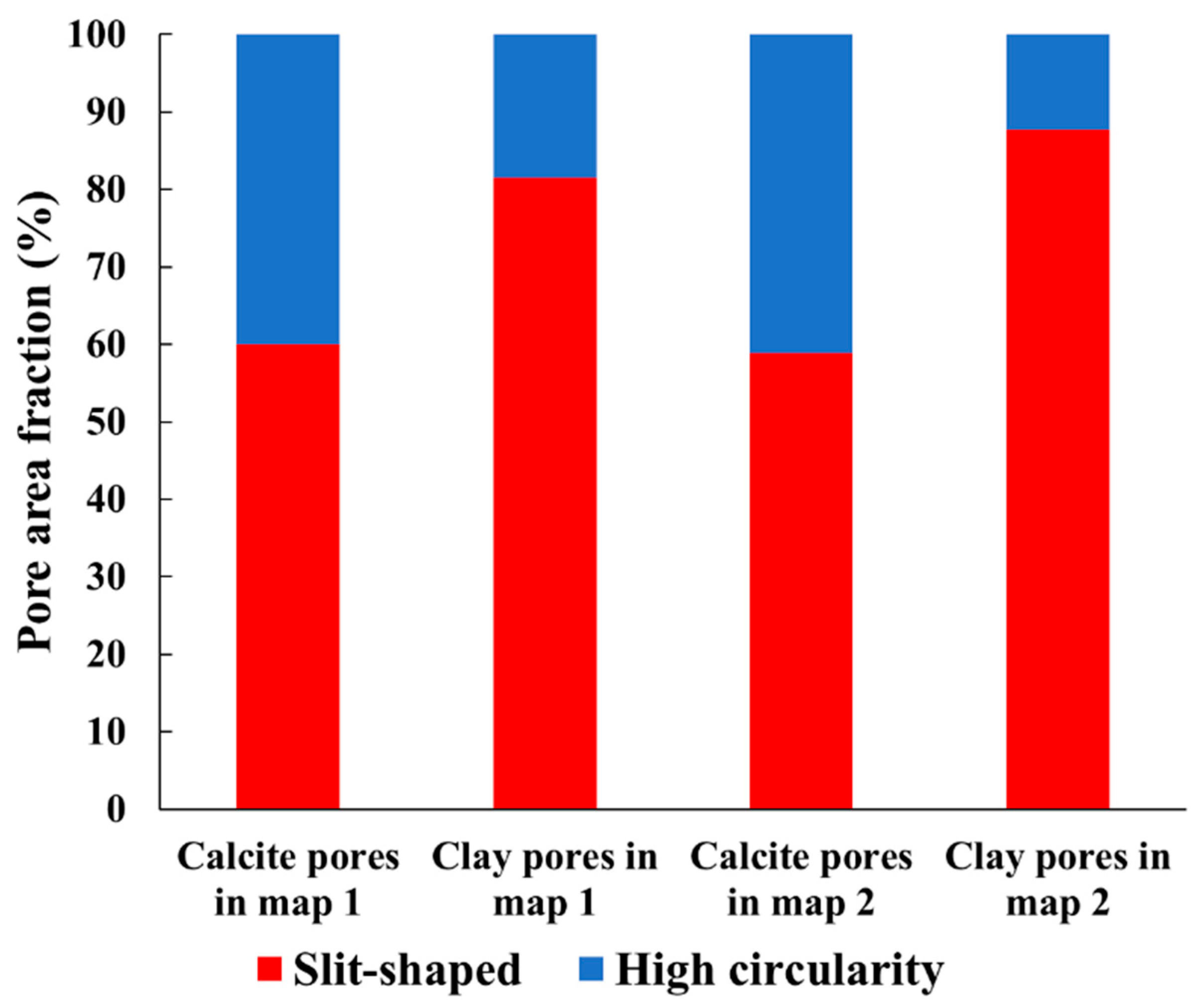
In map 1, the average pore circularity in the clay mineral phase is lower than that of the pores in the calcite phase (0.47 vs 0.59), and the average pore elongation in the clay minerals is higher than that of the pores in calcite (0.62 vs 0.48). The same trends are apparent for pores in map 2. The difference in pore shape factors indicates relatively more slit-shaped pores occurring in the clay fraction. In our study, based on the circularity values, pores in Cobourg limestone are classified as high-circularity pores (0.6 ≤ circularity < 1), slit-shaped pores (0.125 < circularity < 0.6), or fractures (circularity ≤ 0.125, excluded). In the calcite phase, high-circularity and slit-shaped pores account for 40–41% and 59–60%, respectively (Figure 7), whereas slit-shaped pores are dominant in the clay mineral phase (82–88%).

4.2.2. Porosity and Pore Size Distribution

For quantitative porosity and pore size distribution analyses, the PPR is defined as 10 pixels, corresponding to an equivalent area of a circle with a diameter of about 52 nm at a magnification of 20,000×. The total porosities of maps 1 and 2 are 0.68% and 0.41%, respectively (Table 2). These values are lower than the bulk porosity values (0.98–2.51%) determined by HP, which is documented in Hu et al. [17].
In this study, relative porosity is defined as the ratio of pore area or volume to the area or volume of a specific mineral, while absolute porosity is the ratio of pore area or volume to the total area or volume of all mineral phases. Concerning the relative porosities of specific mineral phases, the clay mineral phase is the most porous mineral phase (1.06–1.11%) in both maps, followed by pyrite (0.60–0.88%), calcite (0.24–0.65%), quartz (0.16–0.18%), and dolomite (0.03–0.08%). The absolute porosities of calcite and clay are in the ranges of 0.15–0.58% and 0.09–0.22%, respectively. In total, the pore area within these two phases accounts for 99.7% and 90.9% of the total visible pore areas in maps 1 and 2, respectively.
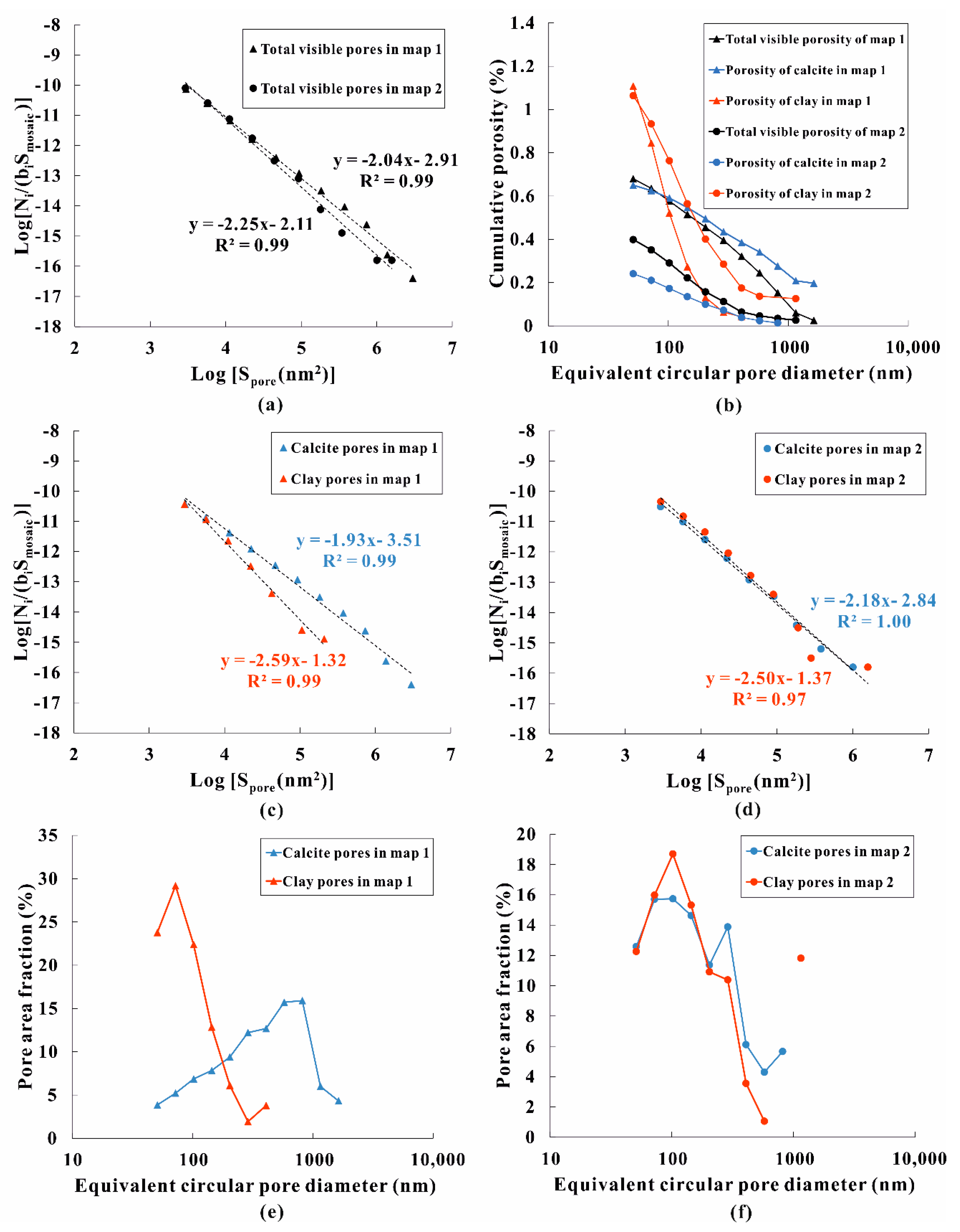
Figure 8a,b shows pore size distributions (pore frequency vs equivalent circular pore diameter) of total visible pores in maps 1 and 2. For both maps, the equivalent circular pore diameter is up to 1155 nm, and the pore frequency decreases with increasing equivalent circular pore diameter. The same trend is also evident for the individual mineral phases (calcite and clay) (Figure 8c–f). The calcite pores in map 1 cover a larger pore size range compared to those in map 2. The majority of clay pores in both maps are smaller than 500 nm.
The logarithm of the pore frequency normalized to the bin width and mosaic area shows a linear correlation with the logarithm of the pore area, indicating self-similar characteristics of the pore size distribution in the Cobourg limestone (Figure 9a,c,d). Power law exponents (D) and constants (logC) for pores in the calcite phase, clay mineral phase, and whole maps are listed in Table 3. The cumulative porosity (relative porosity) in the clay mineral phase increases more strongly than that of the calcite phase with decreasing equivalent circular pore diameter (Figure 9b). Similarly, the pore area fraction in the clay mineral phase increases more strongly, from a relatively low fraction (<5%), with the equivalent circular pore diameter decreasing from 1000 nm to 100 nm (Figure 9e,f). This trend also occurs in the calcite pore area fraction in map 2 (Figure 9f). However, for the calcite pore area fraction in map 1, a peak occurs at an equivalent circular pore diameter ranging from 578 to 817 nm, followed by an approximately linear reduction of the pore area fraction with decreasing equivalent circular pore diameter (Figure 9e).

4.3. FIB-SEM Image Analysis

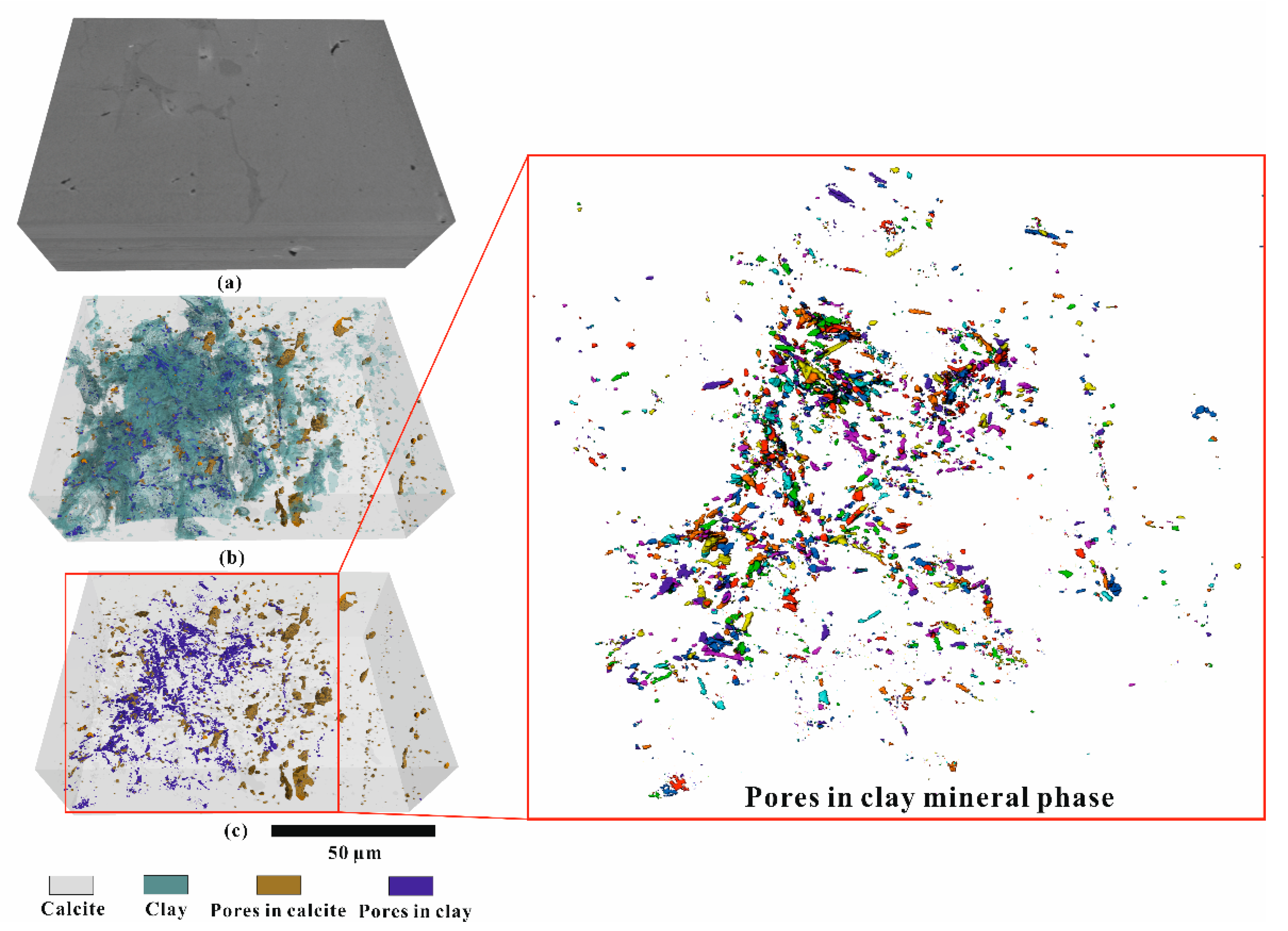
To investigate the three-dimensional pore space connectivity, FIB-SEM tomography is employed to visualize pore networks (Figure 5). The PPR is defined as 8 voxels, corresponding to an equivalent volume of a sphere with a diameter of approximately 25 nm. Analysis of the FIB-SEM volume shows that the volumetric content of the clay mineral phase (green) is 4.39%, and that of the calcite phase (white) is 95.61% (Figure 10). The total porosity of the bulk sample is 0.37%. The relative porosity of the clay mineral phase (green) is 1.46%, which is comparable to the relative porosities of clay mineral phases (1.06–1.11%) obtained from maps 1 and 2 (Table 2). The pore size in the clay mineral phase is up to 570 nm, and the sum of volumetric fractions of pores between 25 and 50 nm are 6.45% (Figure 11a). Regarding the calcite phase, its relative porosity is 0.32%, close to the relative porosity (0.24%) of map 2 (Table 2). The pore size in the calcite phase is up to 760 nm (Figure 11a). Compared to the pore size distribution of the calcite phase, pores with a size larger than 300 nm rarely develop in the clay mineral phase (only a single pore was detected with a maximum equivalent spherical pore diameter of 570 nm). For the calcite phase, the sum of volumetric fractions of pores between 25 and 50 nm is only 0.78%. Evidently, the pore volumes in both clay mineral and calcite phases are dominated by macropores, while the coarse mesopores (25–50 nm) in the clay mineral phase are more abundant than those in the calcite phase (Figure 11a). Similar to the BIB-SEM image analyses, the cumulative porosity (relative porosity) in the clay mineral phase increases more strongly than that of the calcite phase with decreasing equivalent spherical pore diameter (Figure 11b). The logarithm of the 2D pore area linearly correlates with the logarithm of the normalized clay pore frequency in the 498 FIB-SEM images when excluding the data points below the PPR (Figure 11c).
Due to the resolution limitation, identified pores in calcite and clay mineral phases are isolated from each other, and therefore an interconnected pore network could not be constructed (Figure 10). However, shortest distance analysis between pores and their nearest neighbors (edge to edge) shows that 80% of the pores in the clay mineral phase and 41% of pores in the calcite phase are at a distance of ≤100 nm from each other (Figure 11d). The average shortest distances are 83.5 and 224.6 nm in the clay mineral and calcite phases, respectively.

4.4. Permeability Simulation

Permeability estimation using the “bundle of capillary tubes” model from 2D BIB-SEM images were only performed on map 1, as it is representative of the bulk sample with respect to the mineralogy (Table 1). Based on the 2D pore cross-sections, the sum of individual tube permeability coefficients of different mineral phases was expressed as a function of tortuosity (Equation (8)). As the connectivity of pores in calcite and clay mineral phases is unknown, the variation of permeability with increasing tortuosity in three scenarios was present in Figure 12—only pores in clay, only pores in calcite, and pores in both phases contribute to the fluid flow, respectively.
With increasing tortuosity, permeability coefficients will invariably decrease, irrespective of the mineral phase. It should be noted that the tortuosity has to be regarded as a fudge factor with only limited physical meaning [46]. Nevertheless, it has to be used to converge permeability coefficients from BIB-SEM analyses with laboratory measurements (5.21 × 10⁻²⁰–2.74 × 10⁻¹⁹ m2) in Hu et al. [17]. Taking into account all pores in calcite and clay mineral phases, BIB-SEM-derived permeabilities match those from laboratory measurements at a tortuosity range from 8 to 15. Excluding the calcite phase from the calculation, permeability coefficients of the clay mineral phase converge with permeability coefficients measured in the laboratory if the tortuosity is 1. For only pores in calcite contributing to the fluid flow, a similar tortuosity range of 8 to 15 is obtained.

5. Discussion

5.1. Methodological Comparison of Porosity

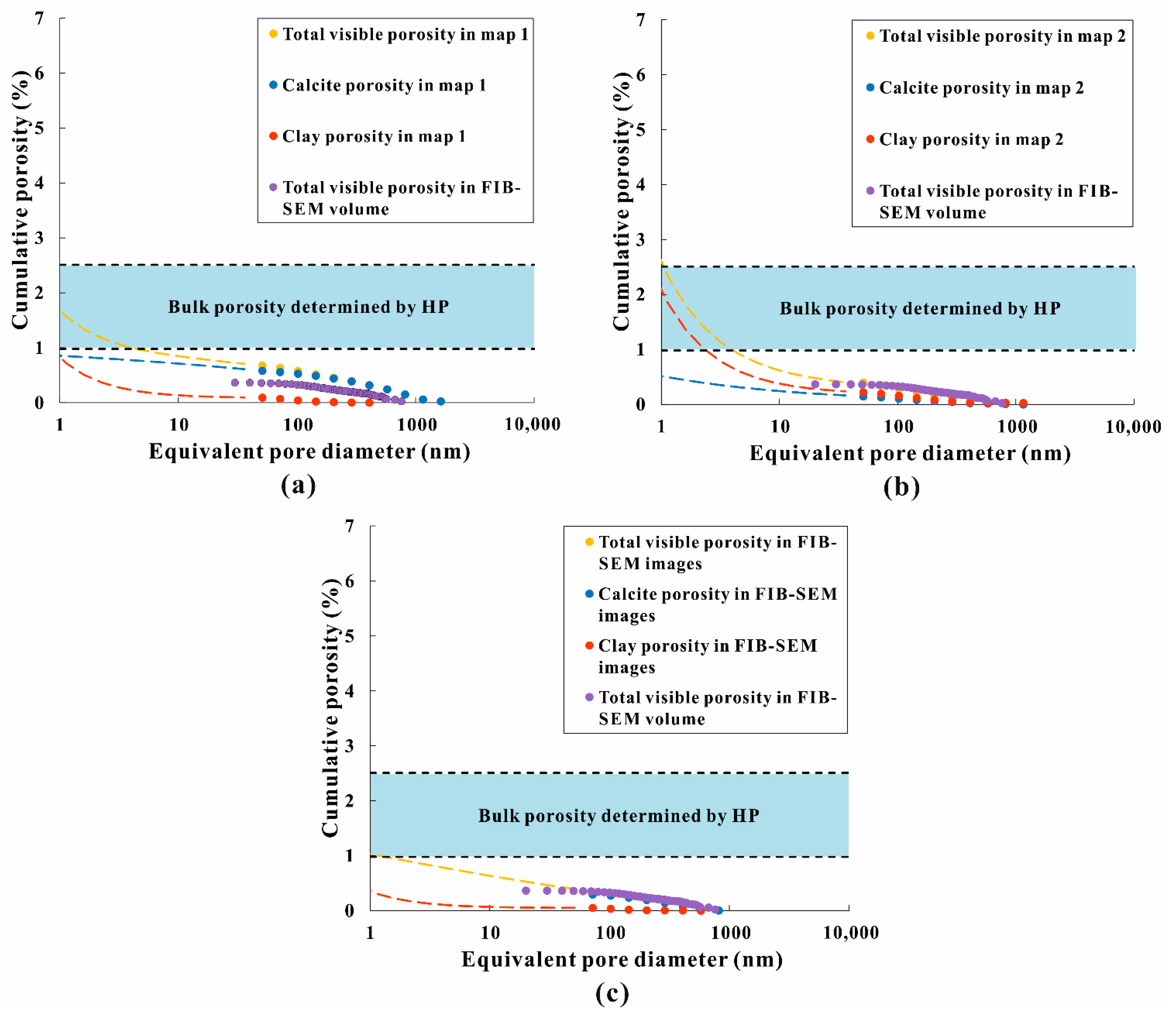
Total porosities obtained from BIB- (0.41% to 0.68%) and FIB-SEM (0.37%) were lower than effective porosities obtained from HP (0.98% to 2.51%), which was documented in Hu et al. [17]. Differences between BIB-SEM- and HP-derived porosities can be attributed either to the resolution of generated BIB-SEM images or sample heterogeneity. Recognition of all pores in the BIB-SEM maps starts from an equivalent circular pore diameter of 52 nm (pore area equivalent to 10 pixels at 20,000×), whereas helium has access to pores down to 0.26 nm [47]. Clay minerals in the Cobourg limestone are dominated by illite and interstratified illite/smectite [17,19]. Since the smallest basal spacing of these TOT type clays (1 octahedral sheet between 2 tetrahedral sheets) is 1 nm [48], D values obtained from imaging analyses were used to extrapolate down to the pore size of 1 nm in order to compare porosities from imaging methods and HP measurements. It is evident for map 1 that after extrapolation, total porosity from map 1 is well within the range of HP-derived porosities (Figure 13a; Table 2), whereas total porosities for map 2 and FIB-SEM images are at the upper and lower boundaries of HP-derived porosities. Similar findings were also made by Klaver et al. [32], who compared MIP- and BIB-SEM-derived porosities of the Haynesville and Bossier shales. This indicates that extrapolation to pore areas that are otherwise unresolved by imaging techniques can be used to give first approximations of HP-derived porosities. It should be noted that HP-derived porosities only give information on the effective (accessible) porosity for helium, whereas BIB-SEM-derived porosities should give information about effective as well as isolated porosities. Since the porosities are in the same range, this could indicate that there is no significant amount of isolated porosity in these maps, as the extrapolated porosities from BIB-SEM images would otherwise have to be higher when compared to HP-derived porosities. In addition, one sample plug was crushed to <63 µm particle size and remeasured for grain density changes by HP. It is shown in Figure 5 that calcite grains are typically larger than 63 µm. If isolated pores were present, even if only a fraction of them were accessible at <63 µm particle size, the grain density should increase. However, no change in grain density was measured (intact rock: 2.723 g/cm3; crushed rock: 2.725 g/cm3), suggesting that the calcite pores are accessible for helium even if the rock fabric is kept intact.
Heterogeneity is always a critical factor in the interpretation of petrophysical rock properties [29,33,42]. It is evident from Figure 13 that HP porosities from Hu et al. [17] vary by an absolute porosity of 1.53% at an average porosity of 1.58%. Additionally, extrapolated total porosities of map 1, map 2, and FIB-SEM images differ strongly, which can be related to a significantly different mineralogical composition (Table 1 and Table 2, Figure 13). Compared to the converted volume fractions of the bulk mineral composition from XRD analysis [17], the highly comparable carbonate and silicate mineral contents of map 1 indicate that map 1 is most representative in terms of mineral composition (Table 1). Extrapolated total porosities from map 1 can be regarded as the most representative porosities when compared to the bulk rock HP measurements, whereas map 2 and FIB-SEM images rather reflect upper and lower boundaries with respect to the heterogenous distribution of clay minerals on the micro scale.

5.2. Pore Morphology and Pore Size Distribution

Based on quantitative analyses of the BIB-SEM images, it is evident that the pore geometry and pore size distribution of the Cobourg limestone are closely related to the mineralogy. Intraparticle and intercrystalline pores are present in the rhombic dolomite and framboidal pyrites, respectively (Figure 6c,d). However, the pyrite clusters are relatively rare and mostly isolated from each other. The dolomite grains are distributed randomly and located at a relatively large distance from each other (Figure 5). Therefore, pores in these mineral phases are deemed irrelevant for fluid flow. In this study, the focus was on the calcite and clay mineral phases, since the pore areas in these two phases represented the majority of the total pore area (up to 99.7%). To investigate the pore morphology, quantitative circularity analyses revealed that most of the visible pores in the clay mineral phase were generally present as slit-shaped pores, whereas those in the calcite phase were present as slit-shaped and high-circularity pores with comparable fractions (Figure 7). Within the common resolvable pore size range (>51 nm), the normalized pore size distributions in the clay mineral phase from FIB-SEM images are similar to those from BIB-SEM images (Figure 11c). D values derived from both methods measured in the clay mineral phase (2.50–2.59) are higher than those measured in the calcite phase (1.93–2.18) (Table 3). Similar findings are reported by Klaver et al. [32] for shales from the Haynesville and Bossier formations. Although no linear relationship exists in the normalized pore size distribution of the calcite phase in the FIB-SEM images, a trend of lower frequencies for pore sizes below 51 nm in the calcite phase as compared to the clay mineral phase is evident (Figure 11c). Therefore, based on the D values, once extrapolated to pores smaller than PPR, the frequency of pores that cannot be resolved by imaging techniques in the clay mineral phase is expected to be much higher than that in the calcite phase.
Calcite pores cover a larger pore size range (up to 1155 nm) in BIB-SEM images, and the majority of clay pores are smaller than 500 nm (Figure 8c–f). A relatively larger volume fraction of large mesopores (25–50 nm) in the clay mineral phase is evident when compared to the calcite phase as well (Figure 11a). Nevertheless, visible pore volumes in both phases are dominated by macropores. However, this observation is probably related to the resolution limit of the imaging technique. It is likely that fine mesopores (2–25 nm) and micropores (<2 nm) significantly influence the total pore volume. This can be seen in Figure 13a, where micro- and mesopores (<50 nm) that cannot be resolved in the BIB-SEM images account for up to 73% of the total pore volume. Overall, the pore size distributions indicate that pores in clay are smaller than those in the calcite fraction.
The pore space distribution of the 3D reconstructed volume from FIB-SEM images is displayed in Figure 10 and indicates that all pores, irrespective of the mineral phase, are isolated. The reason is that the connections (pore throats) of the pores are likely below the resolution of FIB-SEM images. It should be noted that pores in the clay mineral phase are generally closer to each other as compared to those in the calcite phase, which is also indicated by the shortest distance analysis (Figure 11d). Hence, it is more likely that these pores are connected more frequently with pore throats below the resolution (10 nm) of the FIB-SEM images as compared to pores in the calcite phase [24,29,34].
Increasing overall D values in the order of FIB-SEM images (2.04, 4.39% clay content), map 1 (2.04, 8.4% clay content), and map 2 (2.25, 20.9% clay content) illustrate the influence of the clay mineral content on the pore size distribution (a shift towards smaller pores) (Table 3). Philipp et al. [33] studied the pore size distribution of the shaly (75.9–83.6% clay content), sandy (40.6–71.9% clay content), and carbonate-rich (29.6–37.6% clay content) facies of Opalinus Clay and also observed increasing D values with increasing clay mineral content in the order of carbonate-rich facies (1.84–2.05) < sandy facies (2.20–2.43) < shaly facies (2.30–2.50).

5.3. Implications on the Dominant Flow Pathways

This study investigated a potential feasibility of FIB-SEM reconstructed volume as well as 2D BIB-SEM images for permeability simulations in the Cobourg limestone. The main motivation for the image analyses used here is that the Cobourg limestone shows an exceptionally high variability of permeabilities by up to 6 orders of magnitude. This is likely related to combined effects of heterogeneity, anisotropy, and stylolites [17,36] and could potentially be investigated by image analyses. In particular, the existence of a relatively dark (clay-rich) and relatively light (carbonate-rich) fraction was postulated to significantly influence the permeability of the intact limestone [16,18,19], even though only the relatively dark (clay-rich) phase was assumed to be mainly relevant for flow [17,49,50].
In this study, FIB-SEM was performed on such a macroscopically relatively dark (clay-rich) fraction of the rock to investigate transport properties in more detail. However, a lack of pore connectivity and therefore percolation pathways in the FIB-SEM reconstruction implies that permeability simulations are not feasible for this rock using FIB-SEM (i.e., pore throats are below the resolution of imaging). Additionally, FIB-SEM is known to lack rock representativity because of the small sample volume of approximately 1000 µm3 [29,51], which is especially relevant for the heterogenous Cobourg limestone.
Permeability simulations based on 2D images from BIB-SEM showed that permeability coefficients derived from the clay mineral phase could be fitted to the laboratory measurements by assigning a tortuosity value of 1. As clay pore throats cannot be visualized in the high-resolution FIB-SEM images, and clays finely dispersed throughout the rock make up only 6 vol.% of the bulk rock, such an unrealistic tortuosity value [51,52,53] support the interpretation that fluid flow cannot be controlled by pores in the clay mineral phase alone.
Based on detailed characterizations of the pore size distribution, pore morphology, and its connectivity in the calcite and clay mineral phases, arguments for or against the concept that the clay mineral phase exclusively provides flow pathways can be formulated.
Arguments for the clay mineral phase being in charge of fluid flow are:
(a)
Identified pores in the calcite phase are bound to individual grains and therefore could potentially be isolated (Figure 6a). Although calcite is the dominant mineral phase, the clay mineral phase is finely dispersed throughout the whole sample, often enveloping the carbonate grains to a large extent (Figure 5).
(b)
Shortest distance analyses of the FIB-SEM reconstruction indicate that pores in the clay mineral phase are closer to each other than those in the calcite phase, which indicates a higher possibility that these pores are connected.
(c)
The dominant slit-shaped pores in the clay mineral phase are likely to form a connected pore network, considering the high elongation of these pores and highest visible relative porosity (1.06–1.46%).
Arguments against the clay mineral phase being in charge of fluid flow are:
(a)
HP-derived grain densities on intact (plugs) and crushed samples (<63 µm particle size) showed no significant differences. Disruption or destruction of the rock fabric by grinding/milling should make an increasing percentage of pore volume accessible by physically opening isolated pores if existent. It can therefore be concluded that pores in calcite are connected for helium and contribute to transport.
(b)
Extrapolated porosities from mineralogical representative map 1, including calcite and clay mineral phases, are similar to the HP-derived porosities. As the HP-derived porosity measured on plugs represents an effective porosity, this is another piece of supporting evidence that the pores in the calcite phase are not isolated.
(c)
BIB-SEM-derived permeability coefficients for the clay mineral phase can only be matched to laboratory-derived permeability coefficients with a tortuosity value of 1. Such tortuosity appears unrealistic considering that pore throats could not be visualized (e.g., all pores are isolated based on FIB-SEM), and clays are finely dispersed throughout the rock, making up only 6 vol.% of the bulk rock.
(d)
Slit-shaped pores and microfractures are generally more susceptible to deformation than cylindrical pores. Under realistic conditions (burial depths of 250–1000 m for underground mining repositories), the proportion of slit-shaped pores and microcracks would likely be significantly lower than in this study. Additionally, the calcite phase is much more rigid than the clay mineral phase, leading to better preservation potential of pores.
Wood’s metal injection in combination with BIB-SEM could be an alternative to visualize the interconnected pore space at a high resolution over a large area (several mm2). It is an alloy with similar physical properties to mercury, except it melts at 70 ℃. As such, it could be injected into the pore space of the Cobourg limestone at elevated temperatures. Pores would then be gradually filled by increasing the pressure up to 316 MPa (corresponding to an accessible pore size down to 4.1 nm). By decreasing the temperature at maximum pressure, Wood’s metal would again solidify, and pores remain filled. Afterwards, the injected rock samples can be cut, polished and imaged with BIB-SEM [54]. Based on the qualitative and quantitative image analysis, the pore accessibility and connectivity in the calcite and clay mineral phases could be characterized and compared by direct evidence of pores filled with Wood’s metal (down to 10 nm).

6. Conclusions

This contribution aimed to identify the mineral phases and associated microstructures relevant for fluid transport in the intact Cobourg limestone by using multiple imaging techniques covering a wide spectrum of scale (from nanometer to centimeter). The following conclusions can be drawn:
(1)
Based on the mineral composition analysis of BIB-SEM images, the Cobourg limestone can be characterized as a tight rock dominated by calcite grains of variable sizes (µm –cm) surrounded by idiomorphic or subhedral minerals (quartz, dolomite, and pyrite) and meshy clay minerals.
(2)
Qualitative and quantitative pore analyses indicate that calcite and clay mineral phases together contribute over 90% of the total pore areas in two BIB-SEM maps. The clay pores are relatively small and close to each other, dominated by slit-shaped pores, and are interpreted as interparticle pores. The pores associated with calcite have a larger pore size range and are distant from each other, equidimensional, or elongated in shape, and can mostly be considered as intraparticle pores.
(3)
The calcite and clay mineral phases show different pore size distribution, which can be characterized by a power law relationship between pore area and normalized pore frequency. The power law exponent D values measured in the clay mineral phase (2.50–2.59) are higher than those measured in the calcite phase (1.93–2.18).
(4)
The discrepancy in porosity values measured by HP and BIB-SEM can be attributed to the sample heterogeneity and the relatively lower resolution of BIB-SEM. The similarity between extrapolated porosities (down to 1 nm) and bulk porosities measured by HP indicates that valid porosity models can be reached by BIB-SEM imaging and interpretation towards smaller-sized pores, if a representative mineralogy is present in the studied map.
(5)
Based on detailed characterizations of the pore size distribution and pore morphology, and the uncertainty with respect to the connectivity of pores in the calcite and clay mineral phases, it cannot be concluded that the clay mineral phase exclusively provides pathways for flow; rather, it is possible that microfractures in the interface between calcite and clay phases enhance the flow, as well as interconnected pore networks in the calcite phase. However, this has to be investigated in more detail in the future.

Author Contributions

Conceptualization, Z.H. and J.K.; methodology, Z.H.; software, Z.H. and J.D.; formal analysis, Z.H.; investigation, Z.H.; resources, A.A.-H. and J.K.; writing—original draft preparation, Z.H.; writing—review and editing, G.G., A.A.-H., J.K. and S.L.; supervision, R.L.; project administration, R.L. All authors have read and agreed to the published version of the manuscript.

Funding

This research received no external funding.

Data Availability Statement

The data presented in this study are available on request from the corresponding author. The data are not publicly available due to patent protection.

Acknowledgments

Financial support from China Scholarship Council is highly acknowledged.

Conflicts of Interest

The authors declare no conflict of interest.

References

  1. McKinley, I.G. The management of long lived nuclear waste. Energy Policy 1992, 20, 683–692. [Google Scholar] [CrossRef]
  2. Allan, C.; Nuttall, K. How to cope with the hazards of nuclear fuel waste. Nucl. Eng. Des. 1997, 176, 51–66. [Google Scholar] [CrossRef]
  3. International Atomic Energy Agency. The Use of Scientific and Technical Results from Underground Research Laboratory Investigations for the Geological Disposal of Radioactive Waste; International Atomic Energy Agency: Vienna, Austria, 2001. [Google Scholar]
  4. Loubergé, H.; Villeneuve, S.; Chesney, M. Long-term risk management of nuclear waste: A real options approach. J. Econ. Dyn. Control. 2002, 27, 157–180. [Google Scholar] [CrossRef]
  5. Birkholzer, J.; Houseworth, J.; Tsang, C.-F. Geologic Disposal of High-Level Radioactive Waste: Status, Key Issues, and Trends. Ann. Rev. Environ. Resour. 2012, 37, 79–106. [Google Scholar] [CrossRef]
  6. Apted, M.J.; Ahn, J. Geological Repository Systems for Safe Disposal of Spent Nuclear Fuels and Radioactive Waste; Elsevier Science: Amsterdam, The Netherlands, 2017. [Google Scholar]
  7. Witherspoon, P.A.; Bodvarsson, G.S. Geological Challenges in Radioactive Waste Isolation: Fourth Worldwide Review; University of California: Berkley, CA, USA, 2006. [Google Scholar]
  8. Hekimi, B. The Physical and Mechanical Properties of an Argillaceous Limestone; McGill University: Montreal, QC, Canada, 2013. [Google Scholar]
  9. Nasseri, M.; Goodfellow, S.; Wanne, T.; Young, R. Thermo-hydro-mechanical properties of Cobourg limestone. Int. J. Rock Mech. Min. Sci. 2013, 61, 212–222. [Google Scholar] [CrossRef]
  10. Selvadurai, A.P.S. Geomechanical Characterization of the Cobourg Limestone; Nuclear Waste Management Organization TR-2017: Toronto, ON, Canada, 2017. [Google Scholar]
  11. Nguyen, T.; Li, Z.; Su, G.; Nasseri, M.; Young, R. Hydro-mechanical behavior of an argillaceous limestone considered as a potential host formation for radioactive waste disposal. J. Rock Mech. Geotech. Eng. 2018, 10, 1063–1081. [Google Scholar] [CrossRef]
  12. Lippitt, L. Statistical Analysis of Regional Facies Change in Ordovician Cobourg Limestone in Northwestern New York and Southern Ontario. AAPG Bull. 1959, 43, 807–816. [Google Scholar] [CrossRef]
  13. Haeri-Ardakani, O.; Al-Aasm, I.; Coniglio, M. Petrologic and geochemical attributes of fracture-related dolomitization in Ordovician carbonates and their spatial distribution in southwestern Ontario, Canada. Mar. Pet. Geol. 2013, 43, 409–422. [Google Scholar] [CrossRef]
  14. Petts, D.C.; Saso, J.K.; Diamond, L.W.; Aschwanden, L.; Al, T.A.; Jensen, M. The source and evolution of paleofluids responsible for secondary minerals in low-permeability Ordovician limestones of the Michigan Basin. Appl. Geochem. 2017, 86, 121–137. [Google Scholar] [CrossRef]
  15. Vilks, P.; Miller, N.H. Evaluation of experimental protocols for characterizing diffusion in sedimentary rocks. In Atomic Energy of Canada Limited, Nuclear Waste Management Division Report TR-2007-11; Nuclear Waste Management Organization: Toronto, ON, Canada, 2007. [Google Scholar]
  16. Cavé, L.; Al, T.; Xiang, Y.; Vilks, P. A technique for estimating one-dimensional diffusion coefficients in low-permeability sedimentary rock using X-ray radiography: Comparison with through-diffusion measurements. J. Contam. Hydrol. 2009, 103, 1–12. [Google Scholar] [CrossRef] [PubMed]
  17. Hu, Z.; Klaver, J.; Schmatz, J.; Dewanckele, J.; Littke, R.; Krooss, B.M.; Amann-Hildenbrand, A. Stress sensitivity of porosity and permeability of Cobourg limestone. Eng. Geol. 2020, 273, 105632. [Google Scholar] [CrossRef]
  18. Letendre, A. Permeability Changes in Lindsay Limestone Due to Isotropic Compression. Master’s Thesis, McGill University, Montreal, QC, Canada, 2011. [Google Scholar]
  19. Day, J.J.; Diederichs, M.S.; Hutchinson, D.J. The Influence of Mineralogy and Grain Scale Features in Healed Intrablock Structure on Direct Shear Properties in the Cobourg Limestone. In Proceedings of the 51st U.S. Rock Mechanics/Geomechanics Symposium, American Rock Mechanics Association, San Francisco, CA, USA, 25–28 June 2017; p. 12. [Google Scholar]
  20. Hildenbrand, A.; Urai, J.L. Investigation of the morphology of pore space in mudstones-first results. Mar. Pet. Geol. 2003, 20, 1185–1200. [Google Scholar] [CrossRef]
  21. Seemann, T.; Bertier, P.; Krooss, B.M.; Stanjek, H. Water vapour sorption on mudrocks. Geol. Soc. Lond. Spéc. Publ. 2017, 454, 201–233. [Google Scholar] [CrossRef]
  22. Hu, Z.; Gaus, G.; Seemann, T.; Zhang, Q.; Littke, R.; Fink, R. Pore structure and sorption capacity investigations of Ediacaran and Lower Silurian gas shales from the Upper Yangtze platform, China. Géoméch. Geophys. Geo-Energy Geo-Resour. 2021, 7, 1–26. [Google Scholar] [CrossRef]
  23. Klaver, J.; Desbois, G.; Urai, J.L.; Littke, R. BIB-SEM study of the pore space morphology in early mature Posidonia Shale from the Hils area, Germany. Int. J. Coal Geol. 2012, 103, 12–25. [Google Scholar] [CrossRef]
  24. Curtis, M.E.; Sondergeld, C.H.; Ambrose, R.J.; Rai, C.S. Microstructural investigation of gas shales in two and three dimensions using nanometer-scale resolution im-aging. AAPG Bull. 2012, 96, 665–677. [Google Scholar] [CrossRef]
  25. Anovitz, L.M.; Cole, D.R. Characterization and Analysis of Porosity and Pore Structures. Rev. Miner. Geochem. 2015, 80, 61–164. [Google Scholar] [CrossRef] [Green Version]
  26. Cnudde, V.; Boone, M.N. High-resolution X-ray computed tomography in geosciences: A review of the current technology and applications. Earth-Sci. Rev. 2013, 123, 1–17. [Google Scholar] [CrossRef] [Green Version]
  27. Mostaghimi, P.; Blunt, M.; Bijeljic, B. Computations of Absolute Permeability on Micro-CT Images. Math. Geol. 2013, 45, 103–125. [Google Scholar] [CrossRef]
  28. Andrä, H.; Combaret, N.; Dvorkin, J.; Glatt, E.; Han, J.; Kabel, M.; Keehm, Y.; Krzikalla, F.; Lee, M.; Madonna, C.; et al. Digital rock physics benchmarks—part II: Computing effective properties. Comput. Geosci. 2013, 50, 33–43. [Google Scholar] [CrossRef]
  29. Kelly, S.; El-Sobky, H.; Torres-Verdín, C.; Balhoff, M.T. Assessing the utility of FIB-SEM images for shale digital rock physics. Adv. Water Resour. 2016, 95, 302–316. [Google Scholar] [CrossRef]
  30. Saxena, N.; Hofmann, R.; Alpak, F.O.; Berg, S.; Dietderich, J.; Agarwal, U.; Tandon, K.; Hunter, S.; Freeman, J.; Wilson, O.B. References and benchmarks for pore-scale flow simulated using micro-CT images of porous media and digital rocks. Adv. Water Resour. 2017, 109, 211–235. [Google Scholar] [CrossRef]
  31. Desbois, G.; Urai, J.L.; Hemes, S.; Brassinnes, S.; De Craen, M.; Sillen, X. Nanometer-scale pore fluid distribution and drying damage in preserved clay cores from Belgian clay formations inferred by BIB-cryo-SEM. Eng. Geol. 2014, 179, 117–131. [Google Scholar] [CrossRef]
  32. Klaver, J.; Desbois, G.; Littke, R.; Urai, J.L. BIB-SEM characterization of pore space morphology and distribution in postmature to overmature samples from the Haynesville and Bossier Shales. Mar. Pet. Geol. 2015, 59, 451–466. [Google Scholar] [CrossRef]
  33. Philipp, T.; Amann-Hildenbrand, A.; Laurich, B.; Desbois, G.; Littke, R.; Urai, J.L. The effect of microstructural heterogeneity on pore size distribution and permeability in Opalinus Clay (Mont Terri, Switzerland): Insights from an integrated study of laboratory fluid flow and pore morphology from BIB-SEM images. Geol. Soc. Lond. Spéc. Publ. 2017, 454, 85–106. [Google Scholar] [CrossRef]
  34. Keller, L.; Schuetz, P.; Erni, R.; Rossell, M.D.; Lucas, F.; Gasser, P.; Holzer, L. Characterization of multi-scale microstructural features in Opalinus Clay. Microporous Mesoporous Mater. 2013, 170, 83–94. [Google Scholar] [CrossRef]
  35. Bultreys, T.; Van Hoorebeke, L.; Cnudde, V. Multi-scale, micro-computed tomography-based pore network models to simulate drainage in heterogeneous rocks. Adv. Water Resour. 2015, 78, 36–49. [Google Scholar] [CrossRef]
  36. Davy, C.A.; Hu, Z.; Selvadurai, A.P.S.; Klaver, J.; Willemetz, M.C.; Agostini, F.; Skoczylas, F.; Dewanckele, J.; Amann-Hildenbrand, A.; Lenormand, R. Transport properties of the Cobourg Limestone: A benchmark investigation. In Proceedings of the 2019 International Symposium of the Society of Core Analysts, Pau, France, 26–30 August 2019. [Google Scholar]
  37. Masschaele, B.C.; Cnudde, V.; Dierick, M.; Jacobs, P.; Van Hoorebeke, L.; Vlassen, J. UGCT: New x-ray radiography and tomography facility. Nucl. Instrum. Methods Phys. Res. Sect. A Accel. Spectrometers Detect. Assoc. Equip. 2007, 580, 266–269. [Google Scholar] [CrossRef]
  38. Dierick, M.; Van Loo, D.; Masschaele, B.; Boone, M.; Pauwels, E.; Brabant, L.; Van Hoorebeke, L. HECTOR, a new multifunctional micro-CT scanner at UGCT. In Proceedings of the IEEE 10th International Symposium on Biomedical Imaging: From Nano to Macro, San Francisco, CA, USA, 7–11 April 2013. [Google Scholar]
  39. Desbois, G.; Urai, J.L.; Kukla, P.A. Morphology of the pore space in claystones–evidence from BIB/FIB ion beam sectioning and cryo-SEM observations. eEarth Discuss. 2009, 4, 1–19. [Google Scholar] [CrossRef] [Green Version]
  40. Sing, K.S.W.; Everett, D.H.; Haul, R.A.W.; Moscou, L.; Pierotti, R.A.; Rouqérol, J.; Siemieniewska, T. Reporting Physisorption Data for Gas/solid Systems with Special Reference to the Determination of Surface area and Porosity. Pure Appl. Chem. 1985, 57, 603–619. [Google Scholar] [CrossRef]
  41. Ollion, J.; Cochennec, J.; Loll, F.; Escudé, C.; Boudier, T. Tango: A generic tool for high-throughput 3D image analysis for studying nuclear organization. Bioinform. 2013, 29, 1840–1841. [Google Scholar] [CrossRef]
  42. Peters, E.J. Petrophysics; University of Texas at Austin: Austin, TX, USA, 2005. [Google Scholar]
  43. Robie, R.A.; Bethke, P.M. Molar Volumes and Densities of Minerals; United States Department of the Interior Geological Survey: Reston, VI, USA, 1962; pp. 4–21. [Google Scholar]
  44. Loucks, R.G.; Reed, R.M.; Ruppel, S.C.; Hammes, U. Spectrum of pore types and networks in mudrocks and a descriptive classification for matrix-related mudrock pores. AAPG Bull. 2012, 96, 1071–1098. [Google Scholar] [CrossRef] [Green Version]
  45. Al-Mukhtar, M.; Khattab, S.; Alcover, J.-F. Microstructure and geotechnical properties of lime-treated expansive clayey soil. Eng. Geol. 2012, 139–140, 17–27. [Google Scholar] [CrossRef]
  46. Ghanbarian, B.; Hunt, A.; Ewing, R.P.; Sahimi, M. Tortuosity in Porous Media: A Critical Review. Soil Sci. Soc. Am. J. 2013, 77, 1461–1477. [Google Scholar] [CrossRef]
  47. Joos, G.; Freeman, I.M. Theoretical Physics; Dover Publications: Mineola, NY, USA, 1987. [Google Scholar]
  48. Jlassi, K.; Krupa, I.; Chehimi, M.M. (Eds.) Chapter 1-Overview: Clay Preparation, Properties, Modification, in Clay-Polymer Nanocomposites; Matthew Deans: Cambridge, MA, USA, 2017; pp. 1–28. [Google Scholar]
  49. Selvadurai, A.P.S. A Multi-Phasic Perspective of the Intact Permeability of the Heterogeneous Argillaceous Cobourg Limestone. Sci. Rep. 2019, 9, 1–14. [Google Scholar] [CrossRef]
  50. Selvadurai, A.; Głowacki, A. Estimates for the local permeability of the Cobourg limestone. J. Rock Mech. Geotech. Eng. 2018, 10, 1009–1019. [Google Scholar] [CrossRef]
  51. Keller, L.; Holzer, L.; Wepf, R.; Gasser, P. 3D geometry and topology of pore pathways in Opalinus clay: Implications for mass transport. Appl. Clay Sci. 2011, 52, 85–95. [Google Scholar] [CrossRef]
  52. Soeder, D. Porosity and Permeability of Eastern Devonian Gas Shale. SPE Form. Eval. 1988, 3, 116–124. [Google Scholar] [CrossRef]
  53. Backeberg, N.R.; Iacoviello, F.; Rittner, M.; Mitchell, T.; Jones, A.P.; Day, R.; Wheeler, J.; Shearing, P.R.; Vermeesch, P.; Striolo, A. Quantifying the anisotropy and tortuosity of permeable pathways in clay-rich mudstones using models based on X-ray tomography. Sci. Rep. 2017, 7, 1–12. [Google Scholar] [CrossRef]
  54. Klaver, J.; Hemes, S.; Houben, M.; Desbois, G.; Radi, Z.; Urai, J.L. The connectivity of pore space in mudstones: Insights from high-pressure Wood’s metal injection, BIB-SEM imaging, and mercury intrusion porosimetry. Geofluids 2015, 15, 577–591. [Google Scholar] [CrossRef]
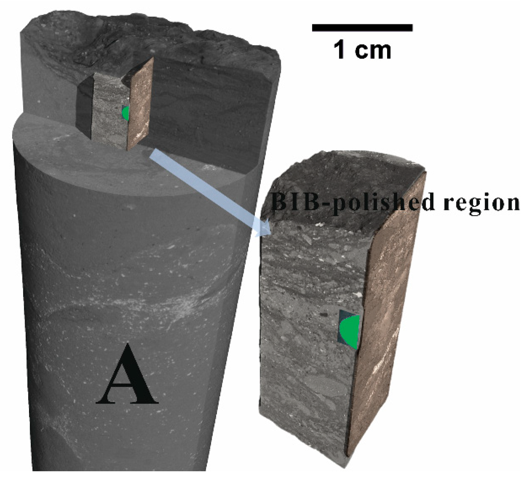
Figure 1. Rendered X-ray micro-CT images of cylindrical sample A and the corresponding micro-core used for BIB-SEM and FIB-SEM experiments (the green region is the BIB-polished area).
Minerals 11 01042 g001
Figure 2. Overview of the studied section and the corresponding regions for BIB- and FIB-SEM. (a) Cross-section of the micro-core which is shown in Figure 1. (b) BSE image (0.72 mm2) of BIB-polished region. Maps 1 and 2 were analyzed quantitatively for mineral composition and pore size distributions. The region for FIB-SEM is located on the upper left corner. (c) The location for FIB-SEM and the exposed cross-section. (d) The BSE image of map 1 showing the distribution of porous calcite and clay.
Minerals 11 01042 g002
Figure 3. Workflow of BIB-SEM image processing (EDX: energy-dispersive X-ray spectroscopy; BSE: backscattered electron; SE2: secondary electron).
Minerals 11 01042 g003
Figure 4. Rendered X-ray micro-CT images of cylindrical sample A (a) and its vertical section (b) at the resolutions of 130 and 30 μm.
Minerals 11 01042 g004
Figure 5. Mineral distribution overview of BIB-polished Cobourg limestone surface (0.72 mm2). The red squares show the areas of BIB-SEM maps 1 and 2 and the location for FIB-SEM.
Minerals 11 01042 g005
Figure 6. BSE images of Cobourg limestone. (a) Angular intraparticle pores with sizes up to a few micrometers in calcite grains and clay minerals randomly distribute among calcite grains. (b) High-resolution image showing the submicron triangular and elongated pores in the clay fraction. (c) Intraparticle pores in rhombus dolomite and microfractures at the interface between carbonate and clay fractions. (d) Intercrystalline pores in framboidal pyrites. (e) Submicron slit-shaped pores in the clay fraction. (f) Microfractures accumulating in the interface of calcite and clay fractions.
Minerals 11 01042 g006
Figure 7. Area fractions of slit-shaped and high-circularity pores in calcite and clay mineral phases of maps 1 and 2.
Minerals 11 01042 g007
Figure 8. Pore frequency distributions (pore frequency vs equivalent circular pore diameter) of total visible pores in BIB-SEM map 1 (a) and map 2 (b). Pore frequency distributions of visible pores in calcite (c) and clay mineral (e) phases of map 1. Pore frequency distributions of visible pores in calcite (d) and clay mineral (f) phases of map 2.
Minerals 11 01042 g008
Figure 9. Normalized pore size distributions of total visible pores in maps 1 and 2 (a). The linear best fit is shown as a dashed line with a corresponding equation. The slope and intercept of the best fit are the minus D and log C values of Equation (2), respectively. Cumulative porosity distributions of total visible pores in maps 1 and 2 and corresponding cumulative porosity distribution of clay and calcite phases (pore area normalized to respective mineral phase area) (b). Normalized pore size distributions in calcite and clay mineral phases of map 1 (c) and map 2 (d). Pore area fraction distributions of calcite and clay mineral phases in map 1 (e) and map 2 (f).
Minerals 11 01042 g009
Figure 10. Dragonfly’s deep learning segmentation results for the FIB-SEM image stack: (a) original greyscale 3D rendered structure of FIB-SEM image stack (10 nm voxel size); (b) clay mineral phase (green) is separated from calcite phase (white), and pores in calcite (gold) and pores in clay (blue) are segmented; (c) 3D distribution of pores in clay and calcite. Neither pores in the calcite nor the clay mineral phase are connected (different colors in the magnified zone are used to differentiate adjacent pores in clay).
Minerals 11 01042 g010
Figure 11. Pore volume fraction distributions (a), cumulative porosity distributions (pore volume normalized to respective mineral phase volume) (b), and normalized pore size distributions based on 2D FIB-SEM image analyses (c). The linear best fit is shown as a dashed line with a corresponding equation. The slope and intercept of the best fit are the minus D and log C values of Equation (2), respectively. The hollow blue and red squares represent the normalized frequencies of pores in calcite and clay when the equivalent circular pore diameter is equal or smaller than 51 nm, respectively. These data points are excluded to obtain linear best fits. The frequency fraction distribution of the shortest distance (edge to edge) between pores and their nearest neighbors in calcite and clay mineral phases of the FIB-SEM volume (d).
Minerals 11 01042 g011
Figure 12. Simulated permeability coefficients based on a range of tortuosity values (≥1) and 2D pore cross-sections in calcite, clay and both mineral phases of map 1. The dashed bounds are the lab-measured permeability range (5.21 × 10⁻²⁰–2.74 × 10⁻¹⁹ m2) of intact Cobourg limestone samples [17].
Minerals 11 01042 g012
Figure 13. Extrapolation of cumulative porosity distributions obtained from BIB-SEM map 1 (a), map 2 (b), and FIB-SEM images (c). Cumulative porosity distribution obtained from FIB-SEM volume (purple data point) and HP bulk porosities (blue zone) from Hu et al. [17] are compared. D and log C values are utilized for the extrapolations of cumulative calcite and clay porosities, which are represented by the blue and red dashed lines, respectively. The extrapolation of cumulative total porosity in map 1 and 2 is the sum of extrapolated cumulative calcite and clay porosities and is represented by the yellow dashed line. As no linear relationship exists in the normalized pore size distribution of calcite phase in 2D FIB-SEM images, D and log C are utilized for the extrapolation of cumulative total porosity and clay porosities in FIB-SEM images. All the porosities here are absolute porosities.
Minerals 11 01042 g013
Table 1. Mineralogical composition obtained from BIB- and FIB-SEM, micro-CT, and XRD analysis of Cobourg limestone.
SampleCalcite (%)Dolomite/Ankerite (%)Clay Minerals (%)Quartz (%)Pyrite (%)Others (%)Carbonate (%)Silicate (%)
BIB-SEM map 189.51.28.40.80.10.090.79.2
BIB-SEM map 261.27.620.98.42.00.068.729.3
FIB-SEM volume95.6 4.39 95.64.39
BIB-SEM overview map84.14.06.54.60.40.588.111.1
XRD analysis *80.08.46.45.00.30.088.411.4
* The weight percentage of each mineral component obtained from XRD analysis was documented in Hu et al. [17] and has been converted to volume fraction by assigning respective density (calcite: 2.71 g/cm3; ankerite: 3.05 g/cm3; clay: 2.75 g/cm3; quartz: 2.65 g/cm3; pyrite: 5.00 g/cm3). Densities of minerals were taken from Robie and Bethke [43].
Table 2. Absolute and relative porosities of different mineral phases in BIB-SEM maps and FIB-SEM volume (relative porosity is the ratio of pore area or volume to the area or volume of a specific mineral; absolute porosity is the ratio of pore area or volume to the total area or volume of all mineral phases).
SamplePorosity (%)CalciteDolomiteClayQuartzPyriteTotal
BIB-SEM map 1Absolute0.580.000.090.000.000.68
Relative0.650.031.110.180.60
BIB-SEM map 2Absolute0.150.010.220.010.020.41
Relative0.240.081.060.160.88
FIB-SEM volumeAbsolute0.30 0.06 0.37
Relative0.32 1.46
Table 3. Power law exponents (D) and constants (logC) for pores in calcite phase, clay mineral phase, and total phases.
Mineral PhaseCalciteClayTotal
DlogCDlogCDlogC
map 11.93−3.512.59−1.322.04−2.91
map 22.18−2.842.50−1.372.25−2.11
FIB-SEM images 2.59 2.04
Publisher’s Note: MDPI stays neutral with regard to jurisdictional claims in published maps and institutional affiliations.