Article

Estimates for the Effective Permeability of Intact Granite Obtained from the Eastern and Western Flanks of the Canadian Shield

by
A. P. S. Selvadurai
1,*,
A. Blain-Coallier
1 and
P. A. Selvadurai
2
1
Department of Civil Engineering and Applied Mechanics, McGill University, 817 Sherbrooke Street West, Montréal, QC H3A OC3, Canada
2
Swiss Seismological Service, ETH Zurich, CH-8092 Zurich, Switzerland
*
Author to whom correspondence should be addressed.
Minerals 2020, 10(8), 667; https://doi.org/10.3390/min10080667
Submission received: 17 June 2020 / Revised: 12 July 2020 / Accepted: 24 July 2020 / Published: 27 July 2020
(This article belongs to the Special Issue The Hydro-Mechanics of Crystalline Rocks)

Abstract

:
Granitic rock from the western part of the Canadian Shield is considered as a potential host rock for the siting of a deep geological repository for the storage of heat-emitting high-level nuclear fuel waste. The research program focused on the use of surface permeability measurements conducted at 54 locations on a 300 mm cuboid of granite, obtained from the Lac du Bonnet region in Manitoba, to obtain an estimate for the effective permeability of the cuboid. Companion experiments are conducted on a 280 mm cuboid of granite obtained from Stanstead, Quebec, located in the eastern part of the Canadian Shield. The surface permeabilities for the cuboids of granite are developed from theoretical relationships applicable to experimental situations where steady flow is initiated at a sealed annular surface region with a pressurized central domain. The experimental values for the surface permeability are used with a kriging procedure to estimate the permeability variations within the cuboidal region. The spatial variations of permeability are implemented in computational models of the cuboidal regions to determine the one-dimensional permeabilities in three orthogonal directions. The effective permeability of the granite cuboids is estimated by appeal to the geometric mean. The research provides a non-destructive methodology for estimating the effective permeability of large specimens of rock and the experiments performed give estimates for the effective permeability of the two types of granitic rock obtained from the western and eastern flanks of the Canadian Shield.

1. Introduction

The cratons found in North America, Fennoscandia, Siberia, Central Africa, Brazil and Australia are extensive, flat, stable interiors of continents that have been relatively undisturbed since the Precambrian era. They consist of large areas of exposed crystalline basement rocks called shields. The Canadian Shield consists of granitic rocks and high-grade metamorphic rocks, including gneisses, together with highly deformed and metamorphosed sediments and volcanic rocks, which would imply intense mountain building episodes in the Precambrian era prior to stable conditions. The Canadian Shield also contains sedimentary formations that were unaffected by mountain building activity and metamorphism. An outline of the surficial outcrop of the Canadian Shield is shown in Figure 1 [1]. The studies related to the Canadian Shield include a rich collection of texts and research articles and no attempt will be made to provide a comprehensive review. Useful summaries are given in the articles [2,3] and the article by Hoffmann [4] contains an excellent overview of cratons in North America and provides an extensive list of research articles on the topic.
Geoscientific and geomechanical interest in plutonic rock masses of the Canadian Shield stems from their potential suitability for the siting of a deep geological repository (DGR) for the long-term storage of heat-emitting nuclear fuels waste. The suitability of the Canadian Shield for such an endeavour is prompted by the relative geotectonic stability of the rock masses in the time scales of interest to the waste disposal effort, which can span up to one million years. The possibility of siting deep geological repositories in granitic rock formations has been investigated by several countries, including Canada, China, Finland, Japan, Korea, Sweden, Switzerland and others. References to concepts and developments associated with high-level nuclear waste disposal can be quite extensive: some key studies are given in [5,6,7,8,9,10,11,12,13,14,15,16,17,18,19,20,21,22,23,24,25,26]. A recent update of the status of the international activities related to proposals for high-level nuclear waste disposal in deep geologic repositories is given in [27]. The development of suitable deep geological disposal concepts for heat-emitting high-level nuclear fuel waste requires urgent attention. Currently most of the fuel waste is stored at the reactor sites, which is an environmental concern since these man-made structures have a finite life span and are prone to degradation with age. The absence of demonstrated strategies for the safe geologic disposal of high-level waste also prevents the promotion of nuclear energy as a viable substitute for fossil fuel-based power generation that contributes to greenhouse gases and attendant climate change.
The plutonic rock of the Canadian Shield as a potential location for the siting of a DGR was investigated by Atomic Energy of Canada Limited as early as the 1970s [28,29,30,31,32,33,34,35,36,37,38,39,40,41,42,43,44,45,46,47,48,49,50,51,52,53,54,55,56,57,58,59,60,61,62,63,64,65,66]. Extensive studies by Atomic Energy of Canada Limited on potential DGR settings that culminated in the construction of the Underground Research Laboratory in the Lac du Bonnet batholith in Pinawa, Manitoba. The provision of an extensive compendium of articles is also to bring to the attention of the reader the considerable volume of research activity accomplished since the 1970s by various research groups. For the convenience of the reader, the scopes of the various articles are summarized according to the following categories: the geological investigations including the geological mapping of the batholith and the fractures within it [50,56,61,64,65], groundwater movement patterns [29,30,42,43,60], geochemistry of groundwater [43,65], rock characterization [54,55], the assessment of the performance of underground openings in highly stressed environments [57,58,59,62,66], the development of scenarios related to disposal vault settings [28,31,33,34,35,39,40,41,45] and glaciation effects on the performance of a disposal facility [47,48,49]. The focus of the Canadian efforts for the deep geological disposal of radioactive waste, both heat-emitting and non-heat emitting, also considers the possibility of argillaceous formations such as the limestone located in southern Ontario [67,68,69,70,71,72]. Extensive studies have been conducted to examine the thermo-hydro-mechanical characteristics of the argillaceous Cobourg limestone, and in the development of computational schemes for both system performance and parameter identification [73,74,75,76,77,78,79,80,81,82,83,84,85,86]. The conceptual layout for a DGR tends to vary with the specific country, but in general, all such repositories rely on a multiple barrier concept that includes sealed waste containers of titanium and/or copper, or copper-coated steel to house the heat-emitting spent fuel bundles, an engineered geological barrier consisting of compacted bentonite to encapsulate the waste containers in boreholes or bentonite clay buffer boxes placed in an in-room setting or in a tunnel or a borehole emplacement configuration [28,31,33,34,35,36,39,40,41,42,43,44,45,70]. The primary natural geological barrier is the rock mass in which the DGR would be constructed. The construction of the DGR in a geologically stressed environment will induce various levels of damage to the rock due to in situ stresses that can include spalling and fracture in the immediate vicinity of the opening DGR [57,58,62] and damage in the form of micro-cracking in regions remote from the DGR opening [76,77]. The feasibility of the DGR concept relies on the multi-barrier concept and the final natural geological barrier is the intact rock mass that is expected to provide the retardation potential to minimize the transport of any radionuclides released from the stored waste to the geosphere and the biosphere. In the long term, the main mode of transport of any released radionuclides will be the groundwater that would establish itself to natural levels upon completion of a DGR. The intact permeability of the rock in a DGR setting is therefore important to the overall feasibility of a DGR as an effective means of providing a reliable setting for the long-term storage of high-level nuclear fuel waste.
This research focuses on the estimation of the isothermal permeability of unstressed granitic rocks obtained from near-surface locations of the eastern and western flanks of the Canadian Shield. The estimation of the permeability of granitic rocks is usually accomplished by conducting either steady state or transient hydraulic pulse tests on cores of the rock. The literature on the topic is extensive and these include the seminal studies by Brace et al. [87] and extensive references to further work in permeability estimation are given in [73,75,76,77,78,79,80,81,82,83,84,88,89,90,91,92,93]. The role of pore fluid migration in plutonic rocks, in particular during their creation, is discussed in [94]. The use of steady state permeability tests on core samples of rocks is perhaps the most straightforward approach for estimating the isothermal permeability of rocks. The interpretation of the permeability requires only the basic information related to the dimensions of the sample, the induced hydraulic gradient, the viscosity of the permeating fluid and its unit weight. When estimating the fluid transport characteristics of rocks with low permeability, the hydraulic pulse test is generally advocated. The interpretation of this test, however, requires additional information such as the compressibility of the porous skeleton, the solid material composing the porous fabric and the pore fluid, along with the porosity of the porous fabric. The interpretation of the test can be influenced by the mathematical theory used to examine the decay of the pressurized fluid cavity in contact with the saturated rock being tested and the compressibility of the fluid in the cavity, which can be influenced by the presence of trapped air [82,83,84]. These limitations have prompted the use of precision pumps that can deliver a flow rate that can be estimated accurately in order to interpret the steady state permeability of low-permeability rocks in general.
The conventional steady state permeability testing of cores recovered from boreholes places a restriction on the sample volume, which is usually restricted to diameters less than 100 mm. With granitic rocks, when heterogeneities are not dominant, the testing of cores at this scale can provide useful information on the bulk intact permeability. If larger cylindrical samples are to be tested, the experimental techniques for performing steady state tests are not routine. Special triaxial testing facilities are required to perform steady state permeability tests on samples measuring up to 150 mm in diameter [74,75,76]. The measurement of permeability characteristics of large cuboidal specimens using localized steady flows induced over a region of the block was first attempted in [95]. The test was rigorously modelled in [96] and experimental application of the technique to measure the permeability characteristics of a large block of Berea sandstone is given in [97]. The numerical evaluation of the intake shape factors that are used to interpret steady state permeability tests conducted on the surface of the porous domain was discussed in [98]. The problem was revisited by Selvadurai [99], who developed a permeameter to create a flow pattern: this involved the sealing of an annular region in contact with a fluid-saturated porous medium. The mathematical developments required to interpret the tests were presented in [97] and the simplified expressions are applicable to permeameters with an annular configuration that can be placed on any planar location of a saturated porous medium to determine the near-surface permeability of the rock. Research was conducted to estimate the near-surface permeability distribution of an Indiana limestone cuboid measuring 508 mm [100,101]. The surface permeability data were used in conjunction with a kriging technique to develop the interior permeability distribution in the cuboid. These data, along with computational modelling of one-dimensional flows through the cuboid, were used to generate the effective permeability of the cuboidal regions. In the present research, the same approach is used to estimate the effective permeability of cubes of the granitic rocks obtained from the eastern (Stanstead, QC, Canada) and western (Lac du Bonnet, MB, Canada) flanks of the Canadian Shield. The visual inspection of the cuboidal samples did not indicate any overt display of anisotropy as would be demonstrated by geologic stratifications. Even in the absence of visible geologic stratifications, micro-mechanical damage due to the in-situ stress state can result in anisotropy. The estimation of all six components of the permeability tensor from a single test is not feasible. What this research aims to accomplish is the description of hydraulic heterogeneity as indicative of the point-wise estimates of permeability derived from a single test giving varying values at the 54 tested locations. The overall goal is to first extrapolate the surface data to estimate interior permeability values; secondly, to convert these permeability estimates to recover an overall effective permeability through a computational approach for estimation bulk flow through the heterogeneous region and to propose the geometric mean as a suitable measure. The primary motivation for the research is to assess the permeability characteristics of competent crystalline rocks similar in origin to those intended to serve as natural geological barriers for radionuclide migration. The research methodologies have wide ranging applications in other geosciences endeavours, ranging from geologic sequestration of greenhouse gases, geothermal energy recovery and energy resources extraction to contaminant transport, where the transport properties of representative volume elements need to be considered to adequately account for heterogeneities at the sample level.

2. Experimental Aspects

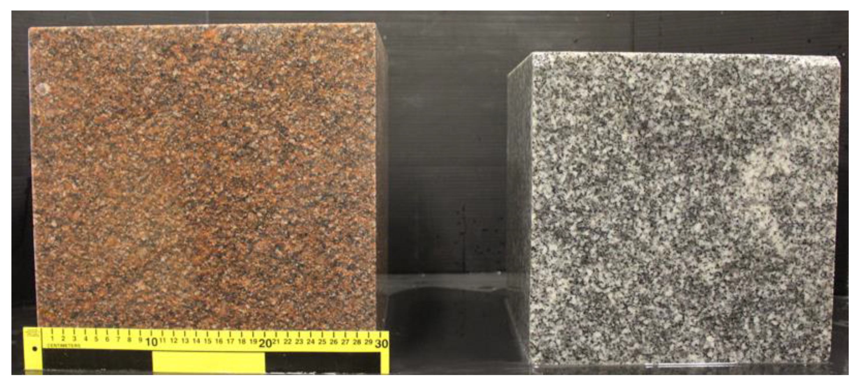
2.1. The Granitic Rocks

The cuboidal sample of Stanstead granite measuring 280 mm was obtained from a supplier in Stanstead, Quebec. The surfaces of the cuboid had a polished texture. The Stanstead granite is a fine-grained rock and XRD testing performed at the McGill Institute for Advanced Materials gave the following mineralogical compositions by volume: Quartz 38.6%; Feldspar 58.9%; Mica 2.5%. Other mechanical and physical properties of the Stanstead granite are documented in the experimental studies presented in [102,103]. Table 1 provides typical results for the mineralogical composition of the Stanstead granite documented in [103,104,105,106]. Investigation of the permeability of the Stanstead granite was presented in [78,79,102]. There was no observable evidence of stratifications that might contribute to permeability anisotropy in the samples of the Stanstead granite used in this research program. Other mechanical and physical properties of the Stanstead granite, including the porosity, bulk unit weight, the elastic modulus, Poisson’s ratio and the thermal conductivity, are given in the references cited.
The Lac du Bonnet granite was supplied by Cold Spring Quarry located in Pinawa, Manitoba. The cuboidal sample used in the research measured 300 mm. XRD testing performed at the McGill Institute for Advanced Materials gave the following mineralogical compositions by volume: Quartz 38.4%; Feldspar 60.2%; Mica 1.4%. Other XRD estimates are also given in [63]. Table 2 contains a summary of the mineralogical compositions obtained for the Lac du Bonnet granite in this and other research.
Figure 2 shows the cuboidal samples. Typical images of 150 mm diameter cores of the two granites are shown in Figure 2. The samples of the Lac du Bonnet granite were obtained from a depth of approximately 16 m and the pink colour is attributed to interaction with groundwater [59,65]. As noted in [63], the pink colour extends to a depth of 185 m, below which the rock exhibits a gray colour similar to the Stanstead granite.

2.2. The Experimental Facilities and Procedures

The surface permeameter was developed by Selvadurai [99] and first used to estimate the near-surface permeability characteristics of a cuboid of Indiana limestone measuring 450 mm. It consists of an arrangement to provide a sealing annular patch region of inner diameter 25.4 mm and outer diameter 101.6 mm. The annular sealing gasket is made of neoprene rubber with a hardness of 40 measured by a Shore A durometer. The sealing is provided by the application of a uniform axial stress over the entire annular region, which is provided by a solid stainless steel housing that also has a water entry port, a de-airing port and an attachment for applying an axial load to develop the sealing action (Figure 3). The permeameter also has stainless steel containing rings to prevent radial expansion of the annular seal both during application of the sealing stress and the internal pressure needed to initiate steady flow. This arrangement also prevents creep deformations of the gasket region that can influence the development of a constant pressure within the interior region of the annulus. The axial sealing stress that needs to be applied to the gasket region will depend on the pressure applied to the interior of the annular seal to develop flow through the rock that is being tested. In the experimental research that involved testing a large cuboidal region of Indiana limestone [100], an axial sealing stress of 1.5 MPa was applied to initiate the sealing action and the fluid pressure applied to initiate flow was less than 250 kPa. The axial load was measured using a load cell (Inter-Technology Model 1200 with a load capacity of 44.5 kN and with an accuracy of +/− 0.04%). The axial load is applied to the permeameter through a hydraulic jack that is attached to a test frame (Figure 2). When testing the granite permeability, the axial sealing stress was maintained at 1.5 MPa and the reliability of the interface sealing action was examined in a separate experiment where the permeameter was in contact with a Plexiglas plate placed on the surface of the granite cuboid. The cavity was subjected to a pressure of 250 kPa and the fluid pressure in the region was sealed. Any time-dependent decay in the cavity fluid pressure at a sealing stress of 1.5 MPa was monitored. The maximum stabilized reduction in cavity pressure over a one-hour period was less than 0.3%. Since the maximum duration of surface permeability tests conducted on both granitic rocks was less than 50 h, the sealing action achieved by the sealing stress of 1.5 MPa was considered to be satisfactory.
The test procedure involved the application of a constant pressure to the central cavity that was maintained using a Quizix 5000 Precision Pump (Chandler Engineering, Broken Arrow, OK, USA) with flow rates that can be varied between 0.0000007 to 30 mL/min. The accuracy of the flow rates supplied by the pumps was verified by the supplier during the installation. The pressurization of the central cavity of the permeameter can be controlled by the pump settings and the cavity pressure is also monitored online using a separate pressure transducer (Honeywell Model THE CP, Honeywell, Charlotte, NC, USA). The precision pump is also capable of monitoring the fluid volume supplied to the cavity at the prescribed pressure. The flow rate established under the prescribed cavity pressure can experience fluctuations and previous investigations suggest that the flow rate supplied to the permeameter is best estimated using the experimental data for the observed cumulative flow volume with time. The water used in the experiments was normal tap water at pH 7.0 . The granitic rocks tested in connection with the research contained virtually no calcite; therefore, the effects of dissolution contributing to permeability alterations during flow can be ignored. The basic requirement in any permeability testing approach is that the pore space of the medium should be saturated with the permeating fluid. In this research, the Stanstead granite, with the anticipated higher permeability, was saturated by placing the sample in a container and allowing water uptake by suction as the water level was progressively increased. Since it was anticipated that the Lac du Bonnet granite would have lower permeability, the cuboidal sample was subjected to vacuum saturation at −10 kPa at room temperature for two weeks. The vacuum saturation procedure involved progressively increasing the depth of the water in the saturation chamber, which allows for the easy withdrawal of air from the pore space of a granite cuboid. The saturation procedure was terminated when water was seen emerging from the upper surface of the nearly immersed granite cuboid. While these procedures can provide some assurance of pore space saturation, maintaining the pore space in a saturated condition cannot be assured since dissolved gases in tap water can be released when the saturation procedure is terminated, and the pore water is in a sessile condition. Therefore, the only way of ensuring that the pore space in the flow domain will be fully saturated is to conduct several surface permeability tests using the permeameter (Figure 3) and to consider the flow domain to be saturated when the times required to achieve steady state and the flow rates are repeatable and stabilized with each subsequent test. In this research, the flow rates stabilized within two successive tests, thus ensuring that the flow paths were within the saturated zone and not influenced by suction effects in regions exterior to the flow domain.
The temperature of the fluid was monitored using two Type K thermocouples. The Quizix 5000 Precision pump was controlled using the PumpWorks Software to regulate and monitor pump performance. All the data from the pump sensors were recorded by the PumpWorks software and other sensors recorded data using a Data Acquisition Module (Model No iNet-400) and the data were recorded and stored in a desktop computer, which was also used for data processing. A general view of the experimental facilities is shown in Figure 4 and a schematic view of the experimental arrangements is shown in Figure 5. A detail of the permeameter and the Lac du Bonnet cuboid assembled for surface permeability testing is shown in Figure 6.

3. Theoretical Aspects

A more complete theoretical development of the surface permeameter is given in [100] and the important concepts and findings relevant to the surface permeability testing of an isotropic porous medium are briefly summarized for completeness. In the testing configuration adopted, the datum head and the velocity head can be neglected in comparison with the pressure head, and Darcy’s law can be written as
v ( x ) = K μ p ( x )
where v ( x ) is the spatially averaged fluid velocity vector (units L/T), K is the isotropic permeability (units L2), μ is the dynamic viscosity of water at the test temperature (units FT/L2), p ( x ) is the fluid pressure (units (F/L2), x is the position vector and is the gradient operator. In (1), we have implicitly assumed that the datum potential and the velocity potential can be neglected in relation to the pressure potential causing flow through the porous medium. Considering the fluid mass conservation applicable to an incompressible fluid, the partial differential equation governing flow is given by
2 p ( x ) = 0
where 2 is Laplace’s operator. When examining the flow induced by the permeameter in the vicinity of the surface of the porous medium, we can assume that the dimensions of the flow domain can correspond to a half-space region, particularly if the permeameter is located on the surface of the cuboidal sample and remote from the edges. Further, since the sealed region is annular, the problem reduces to axisymmetric flow initiated from the annular region, for which (2) takes the form
( 2 r 2 + 1 r r + 2 z 2 ) p ( r , z ) = 0
where r and z are, respectively, the radial and axial coordinates referred to the cylindrical polar coordinate system ( r , θ , z ) . Solutions of (3) applicable to axisymmetric problems associated with a semi-infinite domain take the form [107,108]
p ( r , z ) = 0 ( A ( ξ ) + z B ( ξ ) ) exp ( ξ z ) J 0 ( ξ r ) d ξ
In this configuration, the steady flow from the permeameter to the fluid-saturated half-space region takes place through the interior region of radius a . The exterior of the annular region has a circular boundary of radius b . The mixed boundary conditions associated with the potential problem are
p ( r , 0 ) = p 0 ; 0 r a
p z = 0 ; a r b
p ( r , 0 ) = 0 ; b r <
This three-part mixed boundary value problem can be reduced to a set of triple integral equations, which has been examined by a number of authors (see e.g., [109,110,111,112,113,114,115]), and an approximate solution to the system (8) to (10) can be obtained as a series expansion in terms of the parameter c ( = a / b ) < 1 . The result of interest to the interpretation of the surface permeability tests conducted on the cuboidal regions of both Stanstead and Lac du Bonnet granite is the steady flow rate Q 0 (units L3/T) that will be established from the interior region of the impermeable annulus, when the interior region is subjected to a constant fluid pressure of p 0 , and the exterior region is maintained at zero pressure. The result can be expressed in the form
Q 0 = a p 0 ( K μ ) F ( c )
where
F ( c ) = 4 { 1 + ( 4 π 2 ) c + ( 16 π 4 ) c 2 + ( 64 π 6 + 8 9 π 2 ) c 3 + ( 64 9 π 4 + 256 π 8 ) c 4 + ( 92 225 π 2 + 384 9 π 6 + 1024 π 10 ) c 5 + O ( c 6 ) }
In the limiting case when the permeameter corresponds to a circular entry point of radius a that is located on a sealed surface of a half-space, b , c 0 and (8) gives the exact closed form result
Q 0 = 4 a p 0 ( K μ )
For the aspect ratio of c = 1 / 4 associated with the geometry of the sealing region, (11) reduces to
Q 0 4.458 a p 0 ( K μ )
Detailed computational studies of the performance of the surface permeameter were presented in [99,100]. Computational simulations of the permeameter placed on isolated sub-cuboidal regions (1/27 of the volume of the large Indiana limestone specimen) were performed. These studies concluded that, provided ( b / a ) > 10 , the simplified solution for the flow rate given by (10) can be used to estimate the permeability at a particular location, even if the permeameter is placed in the vicinity of a boundary or in a corner region of the face of a cuboid. In the current study, the result (11) is used to estimate the permeability of the rock irrespective of the location of the permeameter in relation to either the edge or corner regions. The theoretical investigations have also been extended to include transverse isotropy of the rock [116,117,118,119], which provides a basis for the estimation of the permeability of stratified rocks using surface permeameters.

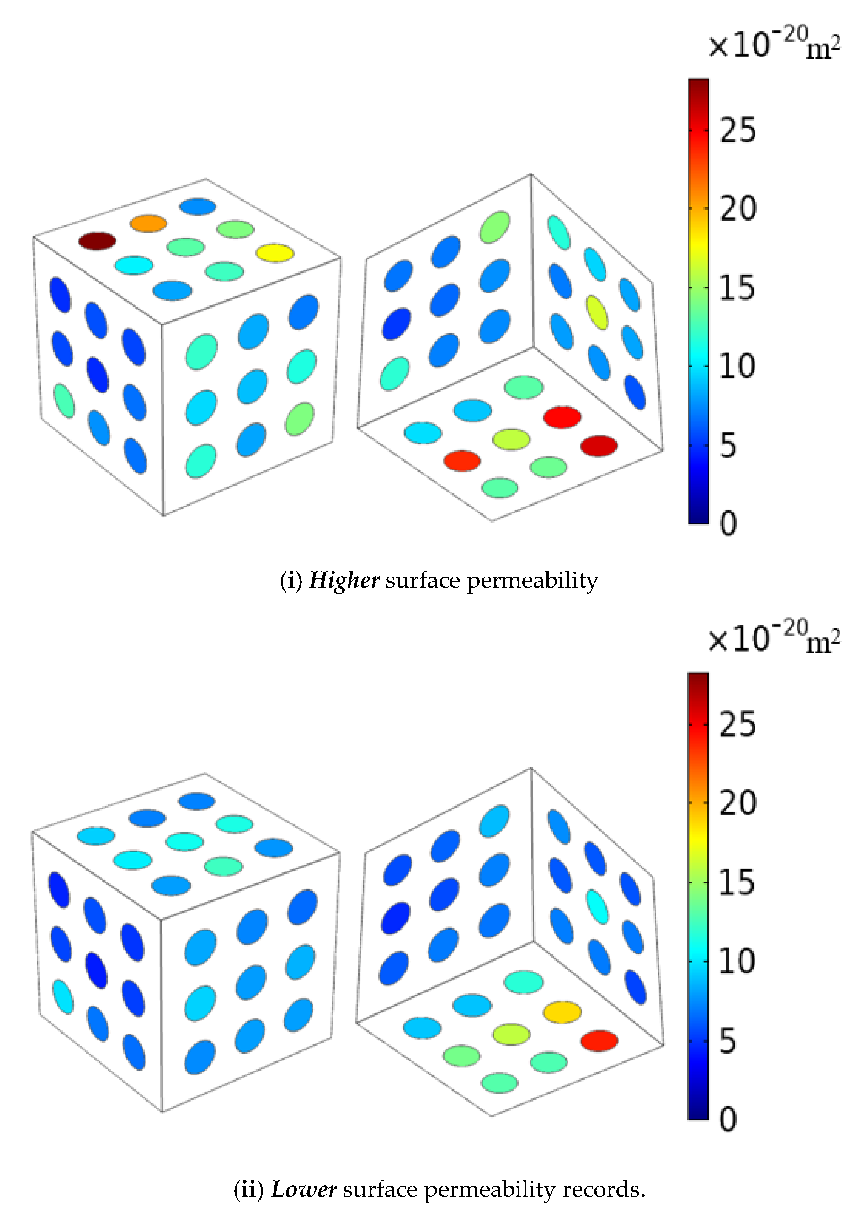
4. Surface Permeability Data

The negative aspect of performing steady state tests is the time required to attain a steady flow rate under a prescribed pressure differential or to attain a steady pressure differential at a prescribed flow rate. As the permeability of the tested rock decreases, the time required to establish a steady state will significantly increase. Therefore, time constraints can influence the number of surface permeability tests that can be performed at any one location of the granite cuboids. In this research, the experiments were restricted to two tests at each location.
In addition, surface permeability measurements were made at nine locations on each of the six faces of the granite cuboids. Two experiments with a constant cavity pressure of 200 kPa were performed at each location to assess the flow rates. The duration of the tests varied between 3 and 70 h. If there was wide variation in the responses, the permeameter was dismantled, re-assembled and the tests were repeated until the flow rate stabilized. In the ensuing, we shall examine the experimental results for the two granites separately. Since the experimental results obtained at the 54 permeameter positions exhibit a range, we propose to evaluate the experimental data by considering the set of values that gives rise to the lower and the higher permeability values recorded at the 54 locations. This will enable the estimation of the effective permeability as a set of bounds rather than a single value obtained by averaging the results at the 54 locations. Table 3 and Table 4 present the observed Higher and Lower permeability values obtained from the two steady state surface permeability tests conducted on the Stanstead granite and the Lac du Bonnet granite, respectively. These tables also indicate the duration of the tests required to achieve a steady state. The time required to achieve the stabilization of the results varied and this could be due to several reasons including re-establishment of new flow paths in the flow domain or the influence of any remnant residual pressure fields in the tested location [91]. Further, the duration of some of the tests was inordinately long primarily to ensure the un-interrupted performance of the Quizix 5000 precision pumps during long-term testing.

4.1. Surface Permeability Data for the Stanstead Granite

Flow rates vs. time and the cumulative volume vs. time at two typical locations of the Stanstead granite cuboid are presented in Figure 7. These results indicate that the flow rates recorded in the permeameter are steady and the record of the cumulative volume vs. time can be used to estimate the flow rate, which in turn is used to estimate the surface permeability of the Stanstead granite cuboid. The surface permeability estimates measured at the 54 locations of the Stanstead granite cuboid are also grouped into the data set that recorded the highest and lowest permeability values. These records are presented in Figure 8.

4.2. Surface Permeability Data for the Lac du Bonnet Granite

Typical results for the flow rates vs. time and the cumulative volume vs. time at one location on the Lac du Bonnet granite cuboid are presented in Figure 9. The results for the cumulative volume vs. time are somewhat different from the data set obtained for the Stanstead granite cuboid. Furthermore, these results were chosen randomly and the remaining data sets (accessible through the URL referred to after the acknowledgements section of this paper) indicate linear variations in the cumulative volume vs. time. It is possible to extract a linear portion of the cumulative volume vs. time to estimate the permeability and if such a procedure is adopted, the results could be subjective. The larger the time interval chosen, the more likely are the results to yield representative values. For the purposes of a comparison, the permeability was also estimated using the time intervals 100 to 300 min, 200 to 400 min and 400 to 600 min shown in Figure 9i and ii. For Figure 9i, the permeability estimates for the three ranges are 3.23 × 10⁻¹⁹ m2, 2.81 × 10⁻¹⁹ m2 and 2.61 × 10⁻¹⁹ m2, respectively, and for the entire time interval, the permeability is 2.58 × 10⁻¹⁹ m2. The average result is closer to the value of the permeability estimated at the latter stages. Similarly, for the results shown in Figure 9ii, the permeability estimates for the three time ranges are 2.85 × 10⁻¹⁹ m2, 2.37 × 10⁻¹⁹ m2 and 2.05 × 10⁻¹⁹ m2, respectively, and for the entire time interval, the permeability is 2.39 × 10⁻¹⁹ m2. While there are differences, they are not large and the procedure of using a larger time interval is retained for uniformity. The data are considered sufficiently accurate for the purposes of estimating a steady state flow rate that can be used to calculate the surface permeabilities at the 54 locations. The records of surface permeability measurements conducted at 54 locations of the Lac du Bonnet granite cuboid can also be grouped into data sets that correspond to the highest and lowest recorded permeability values at the 54 locations. The records of the surface permeability estimates are shown in Figure 10. It is also of interest to assess the accuracy of the permeability estimates derived from the experimental technique. Applying the theory of errors to either the basic result (10) or (11), we can show that the normalized error in the estimation of the permeability can be expressed in the form
d K K = d Q 0 Q 0 + d μ μ d a a d p 0 p 0
where the increments correspond to the error margins. If we assume that the radius a and the dynamic viscosity of water μ can be estimated without error, the accuracy of the measured permeability data reduces to
d K K = d Q 0 Q 0 d p 0 p 0
Considering the accuracy of the measurements, ( d Q 0 / Q 0 ± 0.05 % ;   d p 0 / p 0 ± 0.10 % ) , it can be concluded that the measured values of the permeability can be accurate to within 0.05% to 0.15%.

5. Interior Permeability Estimates

The objective of the experimental research is to provide a technique whereby the results for the surface permeabilities can be used to develop estimates for the spatial permeability distributions in the interior of the cuboidal specimens. The procedures that can be adopted for such estimations can be varied, ranging from the use of kriging procedures to other techniques based upon solids modelling approaches available in codes such as AutoCAD. Recently, the LOFT option in the AutoCAD program was used to map the distribution of heterogeneities in samples of the argillaceous Cobourg limestone measuring 80 × 120 × 8 mm [73]. This procedure was a feasible option when the modelling involved only an extrapolation of surface features through the 8 mm thick region. As shown in [100], for extrapolation of the surface permeabilities to the interior of the three-dimensional cuboidal specimen, recourse must be made to alternative procedures such as kriging. The details of the procedures are given in [100,119] and therefore only the results of the kriging procedure for estimating the distribution of permeability at the interior of the cuboid are recorded here. The kriging procedure was performed using EasyKrig v.3.0 provided in the Matlab software.

5.1. Interior Permeability Distributions for the Stanstead Granite

Using the surface permeability data corresponding to the Higher and Lower permeability data for the Stanstead granite (Figure 8) and the Lac du Bonnet (Figure 10), it is possible to perform statistical evaluations of the datasets. The semi-variograms for the Higher permeability and Lower permeability surface data obtained for the Stanstead granite are shown in Figure 11. We note that the range of the semi-variogram for the Stanstead granite passes the inter-quartile statistical requirements Q1 and Q2 [120].
The interior distribution of the permeability within the Stansted granite cuboid obtained from the kriging procedure can be illustrated by a sub-structuring of the cuboid models using the multiphysics finite element code COMSOL™. Two such realizations are given, the first corresponding to the surface records for the Higher permeability (Figure 12) and the other for the surface records of the Lower permeability (Figure 13). Figure 14 illustrates the probability density distributions of the spatial permeabilities for the Stanstead granite obtained with the kriging procedure and applicable to the Higher and Lower permeability surface data sets.

5.2. Interior Permeability Distributions for the Lac du Bonnet Granite

The methodology presented in Section 5.1 can be extended to develop kriging-based distributions of the interior permeability derived from the surface permeability estimates of the Lac du Bonnet granite. Figure 15 illustrates the semi-variograms applicable to the two surface distributions. The spatial distributions of permeability for the sub-regions of the cuboid of the Lac du Bonnet granite and that are applicable to the Higher and Lower permeability surface data are shown in Figure 16 and Figure 17, respectively. Figure 18 illustrates the probability density distributions of the spatial permeabilities for the Lac du Bonnet granite obtained with the kriging procedure using the Higher permeability and Lower permeability surface data sets. Again, we note that the range of the semi-variograms for the Lac du Bonnet granite passes the inter-quartile statistical requirements Q1 and Q2.

6. Computational Modelling and Estimates for Effective Permeability

The heterogeneous distribution of permeability determined in the previous section was used to estimate the effective permeabilities measured along three orthogonal directions aligned with the edges of the cuboidal regions. These values were estimated using finite element computations of the one-dimensional fluid flow by imposing a constant potential, p ( x ) = p 0 = const . , over one surface of the cuboidal region, zero potential, p ( x ) = 0 , on the surface directly opposite to it and null Neumann or impermeable boundary conditions (i.e., n p = 0 , where n is the outward unit normal to the surfaces) on the remaining four surfaces. The computational multiphysics code COMSOL™ was used for all the finite element simulations of fluid flow. The finite element discretization of the cuboidal regions uses four-noded tetrahedral elements and a typical domain discretization is shown in Figure 19. The mesh of the models simulating different test locations (central, corner and midway) was refined around the annulus region of the permeameter to better describe its circular boundaries. Altogether, 2,053,470 elements were used to model the cuboidal regions. The number of degrees of freedom associated with the discretization was 2,774,035. The computational accuracy of the COMSOL™ Multiphysics finite element code was established through comparisons with known analytical solutions that involved theoretically singular solutions for the flow potential and through inter-code calibrations [76,77,78,79,80,81,82,83,84,85,86,100,101,114,115].
The computational procedure can be used (i) to examine the flow pattern within the cuboidal regions to observe the influence of the permeability heterogeneity on the flow pattern and (ii) to estimate the one-dimensional permeabilities that require the flow paths to preserve the nearly rectilinear uniform flow within the cuboid. The flow patterns obtained for the Stanstead granite for the spatial permeabilities illustrated in Figure 12 and Figure 13 are shown in Figure 20. Similarly, the flow patterns obtained for the Lac du Bonnet granite for the spatial permeabilities illustrated in Figure 16 and Figure 17 are shown in Figure 21. In both instances, the one-dimensional flow paths are largely rectilinear, and the marginal influence of the permeability heterogeneity is observable.
The estimates for the one-dimensional permeabilities in the three-orthogonal directions derived from the Maximum and Minimum estimates of surface permeabilities can be summarized as follows:
(i) For the Stanstead granite
( K x K y K z ) Stanstead Higher = ( 59.2 59.5 59.2 ) × 10 19 m 2
( K x K y K z ) Stanstead Lower = ( 54.6 54.7 54.5 ) × 10 19 m 2
(ii) For the Lac du Bonnet granite
( K x K y K z ) Lac du Bonnet Higher = ( 1.09 1.08 1.10 ) × 10 19 m 2
( K x K y K z ) Lac du Bonnet Lower = ( 0.84 0.83 0.85 ) × 10 19 m 2
As has been pointed out in [100,101], the geometric mean of these experimental estimates can be used as a measure of the effective permeability of the two granites, i.e.,
[ K GM Stanstead ] Higher = [ K x K y K z ) ] Higher Stanstead 3 59.3 × 10 19 m 2 [ K GM Stanstead ] Lower = [ K x K y K z ) ] Lower Stanstead 3 54.6 × 10 19 m 2
[ K GM Lac du Bonnet ] Higher = [ K x K y K z ) ] Higher Lac du Bonnet 3 1.09 × 10 19 m 2 [ K GM Lac du Bonnet ] Lower = [ K x K y K z ) ] Lower Lac du Bonnet 3 0.84 × 10 19 m 2
The results (19) and (20) provide estimates that can be summarized as the set of bounds
54.6 < ( K ) Stanstead 10 19 m 2 < 59.3 ; 0.84 < ( K ) Lac du Bonnet 10 19 m 2 < 1.09
These bounds are sufficiently close that the permeability of the two rocks can be approximated by the algebraic mean of the upper and lower bounds, i.e.,
( K ) Stanstead 57 × 10 19 m 2 ; ( K ) Lac du Bonnet 0.97 × 10 19 m 2
While the geometric mean is a convenient measure [121] for describing the effective permeability of a hydraulically heterogeneous rock, certain criteria need to be satisfied by the permeability distribution, including the Kolomogoroff–Smirnoff test [100], to ensure that the point-wise permeability distribution within the cuboidal region will conform to a log-normal distribution to within a confidence level of 95%. These aspects are further discussed in [100,101]. As an elementary criterion, in order to use the geometric mean as a rational effective measure of the bulk permeability, the permeabilities in the three orthogonal directions should be of the same order of magnitude. The measure will be inapplicable if the internal fabric of the rock gives rise to planes of very low permeability within the structure.
There is the natural tendency to link the accomplishments of the research in terms of simply two estimates for the permeability of the two granites. This would be a naïve interpretation. Firstly, a comparison of the permeabilities of the two types of rocks has not been attempted previously. Secondly, the permeability is estimated from rigorous experimental and theoretical concepts developed in [99,100,101] and in the current context applied to a sample size that would give meaningful interpretations to the concept of a Representative Volume Element (RVE). Furthermore, there is also the urge to suggest the possibility of coring the cuboid to recover samples from the interior of the rock and to estimate the permeabilities of the cores without resorting to the type of experiments performed. This is a valid assertion, which should be balanced by peripheral questions including: what size cores should be made, and at what orientations? Should it be through coring or partial coring? What arrangements should be made to test the remnant material from the coring process? At the scale of the coring size, can processes similar to excavation damage influence the measured permeability? As a further comment, the testing of large cuboidal samples with dimensions in the range of 300 mm which are subjected to triaxial stress states is not a trivial matter and the possibility of subjecting the cuboid to triaxial stress states is not a realistic expectation. The results developed are necessary for the study of a wide range of permeabilities that could be encountered in a DGR setting and in the vicinity of an underground opening and the permeabilities measured will be representative of the rock in a largely unstressed condition. Therefore, the results of the research have a practical context in the sense that in an unstressed condition, the test methodology will give the maximum possible estimate for the permeability and this bound is even more important than the permeability in a stressed state. Coring the block and performing tests on recovered cylindrical samples subjected to triaxial stress are a crude alternative in a research context.

7. Discussion

It is useful to compare the effective permeability estimates for the Stanstead granite and the Lac du Bonnet granite obtained by testing cuboidal specimens measuring 280 and 300 mm, respectively, with the experimental permeability data available from other sources. It should be noted that the majority of published experimental data on Stanstead granite focus on the estimation of the failure and fracture characteristics of the rock: the limited data on permeability values are summarized previously in Table 3. Many of the experimental evaluations of the permeability of Stanstead granite were conducted on small-diameter (50 mm) cylindrical samples and the reference porosity of the Stanstead granite is estimated to be around 0.77%. This result was obtained from water saturation tests conducted at the Environmental Geomechanics Laboratory (EGL McGill University), on 100 mm cuboidal samples of Stanstead granite. Results for both hydraulic pulse tests and steady state flow tests have been reported in the literature. As was observed in [80,82,83,84], the interpretation of pulse tests can be influenced by a number of factors including the degree of saturation and the air voids content in the pressurized fluid; for these reasons, and in keeping with the steady state surface permeability tests conducted on the cuboidal region, only the relevant steady state test data are presented in Table 5.
The Table 6 presents data on permeability values from the published literature for the Lac du Bonnet granite. The laboratory experiments conducted on Lac du Bonnet granite also pay a great deal of attention to the evaluation of the deformability and failure characteristics of the rock and the majority of estimations of permeability were obtained from borehole tests involving hydraulic pulse tests and packer tests. In order to present a data set that can be compared with the surface permeability test results from this research, we summarize the typical laboratory permeability test values of the Lac du Bonnet Granite conducted on cores recovered from boreholes. The reference porosity of the Lac du Bonnet granite is estimated to be around 0.26%.
For reference purposes, the in situ permeability estimates for the Lac du Bonnet granite calculated from borehole hydraulic tests and seepage measurements in open boreholes at the batholith itself give values in the range 0.0025 × 10 19 m 2 to 300 × 10 19 m 2 and most permeabilities measured below 300 m depth were less than 3 × 10 19 m 2 [43]. It should be noted that the field permeability estimates can be influenced by a number of factors including (i) the presence of natural fractures and undetected heterogeneities in the vicinity of the test zone, (ii) borehole damage that can be introduced by the creation of the test borehole and (iii) complex stress states and stress relief due to the creation of the borehole.
The estimation of the permeability ratio can also be attempted by appeal to empirical relationships such as the Kozeny–Carman equation [125,126,127], although the results can be quite sensitive to the porosity estimates. Further, a number of relationships have been added to the original Kozeny–Carman relationships but the most commonly used relationship takes the form
K d 2 ( φ 3 ( 1 φ ) 2 )
where d is a characteristic pore dimension and φ is the porosity. This result can be used to estimate the permeability ratio for the two granites, i.e.,
K Stanstead K Lac du Bonnet = ( φ SG 3 ( 1 φ SG ) 2 ) ( ( 1 φ LdBG ) 2 φ LdBG 3 )
When φ SG 0.0077 and φ LdBG 0.0026 , (23) gives
K Stanstead K Lac du Bonnet 26
When φ SG 0.0077 and φ LdBG 0.0020 , (23) gives
K Stanstead K Lac du Bonnet 58
It is clear that estimating the permeability characteristics of geomaterials by appeal to porosity data is warranted provided the porosity can be estimated with sufficient accuracy.
The prospects for siting a DGR in the eastern parts of the Canadian Shield are remote, primarily because of the proximity to highly populated areas, agricultural and water resources potential of the surficial soils and proximity to the Saint Lawrence Waterways. The low permeability of the parent intact rock on the western flank of the Canadian Shield can be an added consideration in a site selection process.

8. Concluding Remarks

Stable granitic rock formations are one of the geologic settings being considered for the construction of deep geological repositories for the disposal of highly radioactive, heat-emitting and long-lived nuclear fuel waste. The Canadian Shield is a potential setting for the construction of a DGR for nuclear waste disposal. The permeability characteristics of both the intact granite and fractures in the geological setting are important parameters that will control the long-term effects of radionuclide migration from a DGR to the geosphere. The construction of a DGR will perturb the in-situ stress state and this can lead to various levels of local damage and fracturing that can alter the intact permeability of the near field. In regions remote from a DGR, the intact permeability of the rock is expected to be unaltered and together with hydraulically active fractures, represent important factors that will influence groundwater movement, which is an important factor related to radionuclide migration from a DGR. The intact permeability of the granitic rock is expected to be important even in situations where sparse isolated fractures occur; thermo-hydro-mechanical effects can be present in the initial heat-emitting stages of operation of a DGR [44,128] and in the long-term effects associated, for example, with a glaciation sequence [47,48,49,85]. Further, at depth, the closing of mated fractures at high normal stresses can result in significant permeability reductions [129], with the result that the intact permeability becomes a significant part of Thermo-Hydro-Mechanical (THM) modelling exercises.
The effective permeability of granitic rocks sampled from shallow depths at the eastern and western flanks of the Canadian Shield was estimated using experimental data obtained from surface permeability tests conducted on large cuboidal blocks of the rocks. Kriging techniques and computational approaches were used to arrive at estimates for the intact effective permeabilities for the two rock types based on the geometric mean. The experimental results point to roughly a sixty-fold difference in magnitude of the effective permeability estimates between the granitic rocks from the two flanks of the Canadian Shield. Despite this difference in permeability, the mineralogical composition of the two granites are remarkably similar. Moreover, the experimental results presented in the paper relate to the estimation of the permeability of the rocks in an unstressed condition. At depths consistent with the location of a DGR (>500 m), pore closure is expected to occur, which can also lead to permeability reductions.
It is likely that pore closure will occur at depths consistent with the location of a DGR, which could lead to a reduced estimate for the permeability of both rock types. The values reported in this study can therefore be regarded as the upper limits for the permeabilities of the two intact rock types, i.e., ( K ) Stanstead 57 × 10 19 m 2 and ( K ) Lac du Bonnet 0.97 × 10 19 m 2 . The experimental results are consistent with the lower porosity estimates recorded for the granite from Lac du Bonnet in comparison with the Stanstead granite. The geological origins that would lead to the differences in the porosities between the western and eastern flanks of the Canadian Shield are not known since geological information and investigations largely focus on the identification of the mineralogical compositions [130] and occasionally on the physical and mechanical aspects. The cuboidal samples collected for the research program were obtained from near-surface locations where chemical weathering and stress relief following removal of glacial loading can contribute to differences in porosity. Confirmation of these factors, however, requires additional studies.

Author Contributions

The research program and the research were planned and identified by A.P.S.S. The basic experimental concepts, statistical approaches and computational concepts were developed by P.A.S. The experiments were performed by A.B.-C. and the data analysis was performed by A.B.-C. and P.A.S. The final paper was written by A.P.S.S. and checked by P.A.S. All authors have read and agreed to the published version of the manuscript.

Funding

The work described in this paper was supported through NSERC Discovery and Research Tools Grants, the Nuclear Waste Management Organization (NWMO), Toronto, Canada and the Distinguished James McGill Research Chairs program at McGill University.

Acknowledgments

The authors of the paper are grateful to the Technical and Research support provided by J. Bartczak, W. Boyd-Dumais and the research students in the Environmental Geomechanics Laboratory at McGill University including, J. Cardelle, R. Hemmati, V. Zasmolin, P. Samea and Y. Wang. The authors are grateful to the Staff of the Geoscience Research & Development team at NWMO for their continued interest in the work and valuable comments on the drafts of the manuscript. The authors also wish to thank the reviewers for their constructive comments.

Conflicts of Interest

There are no known conflicts of interest.

Data Accessibility

The raw data used in the preparation of the paper can be downloaded from the following site: https://www.mcgill.ca/civil/selvadurai/research-repository.

References

  1. Miall, A.D. Geological Regions in the Canadian Encyclopedia. Available online: https://www.Thecanadianencyclopedia.ca.2015 (accessed on 20 March 2020).
  2. Stockwell, C.H. Tectonic Map of the Canadian Shield; Geological Survey of Canada: Ottawa, ON, Canada, 1965; Map 4. [Google Scholar]
  3. Stockwell, C.H. Geochronology of stratified rocks of the Canadian Shield. Can. J. Earth Sci. 1968, 5, 693–698. [Google Scholar] [CrossRef]
  4. Hoffmann, P.F. United plates of America, the birth of a craton: Early Proterozoic assembly and growth of Laurentia. Ann. Rev. Earth Planet. Sci. 1988, 16, 543–603. [Google Scholar] [CrossRef]
  5. Côme, B.; Johnston, P.; Müller, A. (Eds.) Design and instrumentation of in situ experiments in underground laboratories for radioactive waste disposal. In Proceedings of the Workshop Jointly Organized by Commission of the European Community and OECD Nuclear Energy Agency, Brussels, Belgium; AA Balkema: Rotterdam, The Netherlands, 1985. [Google Scholar]
  6. Laughton, A.S.; Roberts, L.E.J.; Wilkinson, D.; Gray, D.A. The Disposal of Long-lived and Highly Radioactive Wastes. In Proceedings of a Royal Society Discussion Meeting; Royal Society: London, UK, 1986. [Google Scholar]
  7. Tsang, C.-F. (Ed.) Coupled Processes Associated with Nuclear Waste Repositories; Academic Press: New York, NY, USA, 1987. [Google Scholar]
  8. Chapman, N.A.; McKinley, I.G. The Geological Disposal of Nuclear Waste; Wiley: New York, NY, USA, 1987. [Google Scholar]
  9. OECD. Geological Disposal of Radioactive Waste: In Situ Research and Investigation in OECD Countries; NEA Advisory Group, OECD: Paris, France, 1988. [Google Scholar]
  10. Gnirk, P. OECD/NEA International Stripa Project, Overview Volume II. Natural Barriers; SKB: Stockholm, Sweden, 1993. [Google Scholar]
  11. Gray, M.N. OECD/NEA International Stripa Project Overview Volume III Engineered Barriers; SKB: Stockholm, Sweden, 1993. [Google Scholar]
  12. Testa, S.M. Geological Aspects of Hazardous Waste Management; CRC Press: Boca Raton, FL, USA, 1994. [Google Scholar]
  13. Selvadurai, A.P.S. Hydro-thermo-mechanics of engineered clay barriers and geological barriers. Eng. Geol. 1997, 47, 311–379. [Google Scholar] [CrossRef]
  14. Stephansson, O.; Jing, L.; Tsang, C.-F. (Eds.) Coupled Thermo-Hydro-Mechanical Processes of Fractured Media. Developments in Geotechnical Engineering; Elsevier Scientific Publications: Amsterdam, The Netherlands, 1996; Volume 79. [Google Scholar]
  15. Stephansson, O.; Hudson, J.; Jing, L. (Eds.) Coupled Thermo-Hydro-Mechanical-Chemical Processes in Geo-Systems: Fundamentals, Modelling, Experiments and Applications; Elsevier Geo-Engineering Book Series: Amsterdam, The Netherlands, 2004. [Google Scholar]
  16. Miller, W.; Alexander, R.; Chapman, N.; McKinley, J.C.; Smellie, J.A.T. Waste Management Series. In Geological Disposal of Radioactive Wastes and Natural Analogues; Pergamon Press: Amsterdam, The Netherlands, 2000; Volume 2. [Google Scholar]
  17. IAEA. Scientific and Technical Basis for Geologic Disposal of Radioactive Waste; Technical Reports Series No. 413; International Atomic Energy Agency: Vienna, Austria, 2000. [Google Scholar]
  18. NIREX. A Review of the Deep Borehole Disposal Concept for Radioactive Waste; United Kingdom Nirex Limited, Report No. N/108; United Kingdom Nirex Limited: Oxfordshire, UK, 2004. [Google Scholar]
  19. Rutqvist, J.; Rejeb, A.M.T.; Tsang, C.-F. Analyses of coupled hydrological-mechanical effects during drilling of the FEBEX tunnel at Grimsel. In Proceedings of the GeoProc 2003, Stockholm, Sweden, 13–15 October 2003; Volume 44, pp. 114–119. [Google Scholar]
  20. Rutqvist, J.; Chijimatsu, M.; Jing, L.; de Jonge, J.; Kohlmeier, M.; Millard, A.; Nguyen, T.S.; Rejeb, A.; Souley, M.; Sugita, Y.; et al. Stress-Induced Permeability Alterations in an Argillaceous Limestone 1095 Numerical study of the THM effects on the near-field safety of a hypothetical nuclear waste repository-BMT1 of the DECOVALEX III project. Part 3: Effects of THM coupling in fractured rock. Int. J. Rock Mech. Min. Sci. 2005, 42, 745–755. [Google Scholar]
  21. Alonso, E.E.; Alcoverro, J.; Coste, F.; Malinsky, L.; Merrien-Soukatchoff, V.; Kadiri, I.; Nowak, T.; Shao, H.; Nguyen, T.S.; Selvadurai, A.P.S.; et al. The FEBEX benchmark test: Case definition and comparison of modelling approaches. Int. J. Rock Mech. Min. Sci. 2005, 42, 611–638. [Google Scholar] [CrossRef] [Green Version]
  22. Selvadurai, A.P.S. Gravity-driven advective transport during deep geological disposal of contaminants. Geophys. Res. Lett. 2006, 33, L08408. [Google Scholar] [CrossRef] [Green Version]
  23. Brady, P.V.; Arnold, B.W.; Freeze, G.A.; Swift, P.N.; Bauer, S.J.; Kanney, J.L.; Rechard, R.P.; Stein, J.S. Deep Borehole Disposal of High-Level Radioactive Waste; SAND 2009-4401; Sandia National Laboratory Report: Alberqueque, NM, USA, 2009. [Google Scholar]
  24. Pusch, R.; Yong, R.N.; Nakano, M. High-Level Radioactive Waste (HLW) Disposal: A Global Challenge; WIT Press: Southampton, UK, 2011. [Google Scholar]
  25. Yardley, B.W.D.; Ewing, R.C.; Whittleston, R.A. Deep-mined geological disposal of radioactive waste. Elements 2016, 12, 233–274. [Google Scholar]
  26. Selvadurai, A.P.S.; Suvorov, A.P. Thermo-Poroelasticity and Geomechanics; Cambridge University Press: Cambridge, UK, 2016. [Google Scholar]
  27. Faybishenko, B.; Birkholzer, J.; Sassani, D.; Swift, P. (Eds.) International Approaches for Deep Geological Disposal of Nuclear Waste: Geological Challenges in Radioactive Waste Isolation. Fifth Worldwide Review; Lawrence Berkeley National Laboratory: Berkeley, CA, USA, 2016; LBNL-1006984. [Google Scholar]
  28. Boulton, J. Management of Radioactive Wastes: The Canadian Disposal Program; Atomic Energy of Canada Limited Report AECL-6314; Whiteshell Laboratories: Pinawa, MB, Canada, 1978. [Google Scholar]
  29. Davison, C.C. Physical Hydrogeology Measurements Conducted in Boreholes WN-1, WN-2 and WN-4 to Assess the Local Hydrogeologic Conductivity and Hydraulic Potential of a Granitic Rock Mass; Atomic Energy of Canada Limited Technical Record, TR-26; Whiteshell Laboratories: Pinawa, MB, Canada, 1980. [Google Scholar]
  30. Davison, C.C. Monitoring hydrogeologic conditions in fractured rock at the site of Canada’s Underground Research Laboratory. Groundw. Mon. Rev. 1984, 4, 95–102. [Google Scholar] [CrossRef]
  31. Bird, G.W.; Cameron, D.J. Vault Sealing Research for the Canadian Nuclear Fuel Waste Management Program; Atomic Energy of Canada Report AECL-TR 145; Whiteshell Laboratories: Pinawa, MB, Canada, 1982. [Google Scholar]
  32. Simmons, G.R.; Soonawala, N.M. (Eds.) Underground Research Laboratory: Underground Experimental Program; Atomic Energy of Canada Limited, Technical Record TR-153; Whiteshell Laboratories: Pinawa, MB, Canada, 1982. [Google Scholar]
  33. Simmons, G.R.; Baumgartner, P. The Disposal of Canada’s Nuclear Fuel Waste: Engineering for a Disposal Facility; Atomic Energy of Canada Limited, Technical Record AECL-10715, COG-93-6.-153; Whiteshell Laboratories: Pinawa, MB, Canada, 1994. [Google Scholar]
  34. Simmons, G.R.; Baumgartner, P.; Bird, G.A.; Davison, C.C.; Johnson, L.H.; Tamm, J.A. An Approach to Criteria, Design Limits and Monitoring in a Nuclear Waste Disposal Vault; Atomic Energy of Canada Limited Report, AECL-10737, COG 94-30; Whiteshell Laboratories: Pinawa, MB, Canada, 1994. [Google Scholar]
  35. Lopez, R.S. Review of vault sealing research. In Proceedings of the 19th Information Meeting of the Nuclear Fuel Waste Management Program, Toronto, ON, Canada, September 1985; Atomic Energy of Canada Limited Report TR 350. Volume III, pp. 499–512. [Google Scholar]
  36. Hancox, W.T. Progress in the Canadian nuclear fuel waste management program. In Proceedings of the Canadian Nuclear Society 2nd International Conference on Radioactive Waste Management, Winnipeg, MB, Canada, 7–11 September 1986. [Google Scholar]
  37. Scott, J.S.; Gibb, R.A. Results of geoscience research in the Canadian Nuclear Fuel Waste Management Program: Introduction. Can. J. Earth Sci. 1989, 26, 341–344. [Google Scholar] [CrossRef]
  38. Brown, A.; Soonawala, N.M.; Everitt, R.A.; Kamineni, D.C. Geology and geophysics of the Underground Research Laboratory site, Lac du Bonnet batholith, Manitoba. Can. J. Earth Sci. 1989, 26, 404–425. [Google Scholar] [CrossRef]
  39. Simmons, G.R.; Baumgartner, P. The Disposal of Canada’s Nuclear Fuel Waste: Engineering for a Disposal Facility; AECL Res Rep AECL-10715, COG-93-5; Whiteshell Laboratories: Pinawa, MB, Canada, 1994. [Google Scholar]
  40. Johnson, L.H.; LeNeveau, D.M.; Shoesmith, D.W.; Oscarson, D.W.; Gray, M.N.; Lemire, R.J.; Garisto, C. The Disposal of Canada’s Nuclear Fuel Waste: The Vault Model for Post-Closure Assessment; AECL Research Report AECL-1071; Whiteshell Laboratories: Pinawa, MB, Canada, 1994. [Google Scholar]
  41. Johnson, L.H.; Tait, J.C.; Shoesmith, D.W.; Crosthwaite, J.L.; Gray, M.N. The Disposal of Canada’s Nuclear Fuel Waste: Engineered Barriers Alternatives; AECL Research Report AECL-10718, COG-93-8; Whiteshell Laboratories: Pinawa, MB, Canada, 1994. [Google Scholar]
  42. Stevenson, D.R.; Kozak, E.T.; Davison, C.C.; Gascoyne, M.; Broadfoot, R.A. Hydrogeologic Characteristics of Domains of Sparsely Fractured Rock in the Granitic Lac du Bonnet Batholith; AECL-11558, COG-96-117; Atomic Energy of Canada Limited, Whiteshell Laboratories: Pinawa, MB, Canada, 1996. [Google Scholar]
  43. Stevenson, D.R.; Brown, A.; Davison, C.C.; Gascoyne, M.; McGregor, R.G.; Ophori, D.U.; Schier, N.W.; Stanchell, F.; Thorne, G.A.; Tomsons, D.K. A Revised Conceptual Hydrogeologic Model of a Crystalline Rock Environment, Whiteshell Research Area, Southeastern Manitoba; Canada, AECL-11331, COG-95-271; Atomic Energy of Canada Limited; Whiteshell Laboratories: Pinawa, MB, Canada, 1996. [Google Scholar]
  44. Selvadurai, A.P.S.; Nguyen, T.S. Scoping analyses of the coupled thermal-hydrological-mechanical behaviour of the rock mass around a nuclear fuel waste repository. Eng. Geol. 1996, 47, 379–400. [Google Scholar] [CrossRef]
  45. Graham, J. The Buffer-Container Experiment: Results, Synthesis, Issues; AECL Research Report AECL-1174, COG-97-46-1; Whiteshell Laboratories: Pinawa, MB, Canada, 1997. [Google Scholar]
  46. Chandler, N.A. Twenty-five years of underground research at Canada’s URL. In Proceedings of the Waste Management ’03 Conference, Tucson, AZ, USA, 23–27 February 2003; pp. 1–15. [Google Scholar]
  47. Chan, T.; Stanchell, F.W. Subsurface hydro-mechanical (HM) impacts of glaciation: Sensitivity to transient analysis, HM coupling, fracture zone connectivity and model dimensionality. Int. J. Rock Mech. Min. Sci. 2005, 42, 828–849. [Google Scholar] [CrossRef]
  48. Chan, T.; Stanchell, F.W. DECOVALEX THMC TASK E-Implications of Glaciation and Coupled Thermohydromechanical Processes on Shield Flow System Evolution and Performance Assessment; NWMO TR-2008003; Nuclear Waste Management Organization: Toronto, ON, Canada, 2008. [Google Scholar]
  49. Chan, T.; Christiansson, R.; Boulton, G.S.; Ericsson, L.O.; Harikainen, J.; Jensen, M.R.; Mas Ivars, D.; Stanchell, F.W.; Vistrand, P.; Wallroth, T. DECOVALEX III BMT 3/BENCH-PAR WP4: The thermo-hydro-mechanical responses to a glacial cycle and their potential implications for deep geological disposal of nuclear fuel waste in a fractured crystalline rock mass. Int. J. Rock Mech. Min. Sci. 2005, 42, 805–827. [Google Scholar] [CrossRef]
  50. Tammemagi, H.Y.; Kerford, P.S.; Requeima, J.C.; Temple, C.A. A Geological Reconnaissance Study of the Lac du Bonnet Batholith; AECL-6439; Whiteshell Nuclear Research Establishment: Pinawa, MB, Canada, 1980. [Google Scholar]
  51. Wallace, D.E. Radioactive Waste Management in Canada: AECL Publications and Other Literature; AECL-6186 Rev3; AECL Research Whiteshell Laboratories: Pinawa, MB, Canada, 1983. [Google Scholar]
  52. McCrank, G.F.D. Geological Survey of the Lac du Bonnet Batholith, Manitoba; Atomic Energy of Canada Limited Report AECL 7816; Whiteshell Laboratories: Pinawa, MB, Canada, 1985. [Google Scholar]
  53. Hawley, N.J. Radioactive Waste Management in Canada: AECL Publications and Other Literature 1983–1985; AECL-6186 Rev4; AECL Research Whiteshell Laboratories: Pinawa, MB, Canada, 1986. [Google Scholar]
  54. Jackson, R.; Lau, J.S.O.; Annor, A. Mechanical, thermo-mechanical and joint properties of rock samples from the site of the AECL’s Underground Research Laboratory, Lac du Bonnet, Manitoba. In Proceedings of the 42nd Can. Geotech. Conference, Winnipeg, MB, Canada, 1986; pp. 41–49. [Google Scholar]
  55. Jackson, R.; Annor, A. Thermomechanical Properties of Rock Samples from Lac du Bonnet and Eye Dashwa Lakes Plutons; Divisional Report ERP/MRL 85042 (TR); CANMET, Energy Mines and Resources: Ottawa, ON, Canada, 1989. [Google Scholar]
  56. Stone, D.; Kamineni, D.C.; Brown, A.; Everitt, R. A comparison of fracture styles in two granite bodies of the Superior Province. Can. J. Earth Sci. 1989, 26, 387–403. [Google Scholar] [CrossRef]
  57. Martin, C.D. Failure observations and in situ stress domains at the Underground Research Laboratory. In Proceedings of the Conference on Rock Mech. and Rock Physics at Great Depth, Pau, France; Maury, V., Fourmaintraux, D., Eds.; A.A. Balkema: Rotterdam, The Netherlands, 1989; Volume 2, pp. 719–726. [Google Scholar]
  58. Martin, C.D. Characterizing in situ stress domains at the AECL Underground Research Laboratory. Can. Geotech. J. 1990, 27, 631–646. [Google Scholar] [CrossRef]
  59. Martin, C.D.; Stimpson, B. Effect of sample disturbance on laboratory properties of Lac du Bonnet granite. Can. Geotech. J. 1994, 31, 692–702. [Google Scholar] [CrossRef]
  60. Whitaker, S.H.; Brown, A.; Davison, C.C.; Gascoyne, M.; Lodha, G.S.; Stevenson, D.R.; Thorne, G.A.; Tomsons, D. AECL Strategy for Surface-Based Investigations of Potential Disposal Sites and the Development of a Geosphere Model for a Site; AECL Research Whiteshell Laboratories: Pinawa, MB, Canada, 1994. [Google Scholar]
  61. Everitt, R.; McMurray, J.; Brown, A.; Davison, C. Geology of the lac du Bonnet Batholith Inside and Out: AECL’s Underground Research Laboratory, Southeastern Manitoba (Field B5). In Proceedings of the Geological Association of Canada, Joint Annual Meeting, Winnipeg, MB, Canada, 27–29 May 1996; pp. 1–72. [Google Scholar]
  62. Read, R.S.; Martin, C.D. Technical Summary of AECL’s Mine-by Experiment. Phase 1: Excavation Response; AECL-11311, COG-95-171; Whiteshell Laboratories: Pinawa, MB, Canada, 1996. [Google Scholar]
  63. Duevel, B.; Haimson, B. Mechanical characterization of pink lac du Bonnet granite: Evidence of non-linearity and anisotropy. Int. J. Rock Mech. Min. Sci. 1997, 34, 3–4. [Google Scholar] [CrossRef]
  64. Gascoyne, M.; Brown, A.; Ejeckam, R.B.; Everitt, R.A. Dating Fractures and Fracture Movement in the Lac du Bonnet Batholith; AECL Research Report AECL-11725, COG 96-634-1; Whiteshell Laboratories: Pinawa, MB, Canada, 1997. [Google Scholar]
  65. Gascoyne, M. Hydrogeochemistry, groundwater ages and sources of salts in a granitic batholith on the Canadian Shield, southeastern Manitoba. Appl. Geochem. 2004, 19, 519–560. [Google Scholar] [CrossRef]
  66. Everitt, R.; Lajtai, E.Z. The influence of the rock fabric on excavation damage in the Lac du Bonnet granite. Int. J. Rock Mech. Min. Sci. 2004, 41, 1277–1303. [Google Scholar] [CrossRef]
  67. NWMO. Ontario Power Generation’s Deep Geologic Repository for Low and Intermediate Level Waste. Post-closure Safety Assessment; NWMO DGR-TR-2011-25; Nuclear Waste Management Organization: Toronto, ON, Canada, 2011. [Google Scholar]
  68. NWMO. Ontario Power Generation’s Deep Geologic Repository for Low and Intermediate Level Waste. Geosynthesis; NWMO DGR-TR-2011-11; Nuclear Waste Management Organization: Toronto, ON, Canada, 2011. [Google Scholar]
  69. NWMO. People, Science, Indigenous Knowledge. Moving Towards Partnership; Annual Report of the Nuclear Waste Management Organization; Nuclear Waste Management Organization: Toronto, ON, Canada, 2017; pp. 1–104. [Google Scholar]
  70. NWMO. NWMO’s Program for Research and Development for Long-Term Management of Used Nuclear Fuel; NWMO TR-2019-18; Nuclear Waste Management Organization: Toronto, ON, Canada, 2019. [Google Scholar]
  71. OPG. Ontario Power Generation’s Deep Geologic Repository for Low and Intermediate Level Waste: DGR: Protecting Lake Huron; Ontario Power Generation: Toronto, ON, Canada, 2016; Available online: www.opg.com/dgr (accessed on 20 March 2020).
  72. Selvadurai, A.P.S. Geomechanical Characterization of the Cobourg Limestone; Nuclear Waste Management Organization Technical Report NWMO-TR-2017-7; Nuclear Waste Management Organization: Toronto, ON, Canada, 2017. [Google Scholar]
  73. Selvadurai, A.P.S. A multi-phasic perspective of the intact permeability of the heterogeneous argillaceous Cobourg limestone. Sci. Rep. 2019, 9, 17388. [Google Scholar] [CrossRef]
  74. Selvadurai, A.P.S. The Biot coefficient for a low permeability heterogeneous limestone. Contin. Mech. Thermodyn. 2019, 31, 939–953. [Google Scholar] [CrossRef]
  75. Selvadurai, A.P.S.; Letendre, A.; Hekimi, B. Axial flow hydraulic pulse testing of an argillaceous limestone. Environ. Earth Sci. 2011, 64, 2047–2058. [Google Scholar] [CrossRef]
  76. Selvadurai, A.P.S.; Głowacki, A. Stress-induced permeability alterations in an argillaceous limestone. Rock Mech. Rock Eng. 2017, 50, 1079–1096. [Google Scholar] [CrossRef]
  77. Selvadurai, A.P.S.; Głowacki, A. Estimates for the local permeability of the Cobourg limestone. Rock Mech. Geotech. Eng. 2018, 10, 1009–1019. [Google Scholar] [CrossRef]
  78. Selvadurai, A.P.S. Fluid leakage through fractures in an impervious caprock embedded between two geologic aquifers. Adv. Water Resour. 2012, 41, 76–83. [Google Scholar] [CrossRef]
  79. Selvadurai, A.P.S.; Suvorov, A.P. Boundary heating of poroelastic and poro-elastoplastic spheres. Proc. R. Soc. Math. Phys. Sci. Ser. A 2012, 469, 2779–2806. [Google Scholar] [CrossRef] [Green Version]
  80. Selvadurai, A.P.S.; Najari, M. On the interpretation of hydraulic pulse tests on rock specimens. Adv. Water Res. 2013, 53, 139–149. [Google Scholar] [CrossRef]
  81. Selvadurai, A.P.S.; Suvorov, A.P. Thermo-poromechanics of a fluid-filled cavity in a fluid-saturated porous geomaterial. Proc. R. Soc. Math. Phys. Sci. Ser. A 2014, 470, 20130634. [Google Scholar] [CrossRef]
  82. Selvadurai, A.P.S.; Najari, M. Laboratory-scale hydraulic pulse testing: Influence of air fraction in cavity on estimation of permeability. Geotechnique 2015, 65, 126–134. [Google Scholar] [CrossRef]
  83. Selvadurai, A.P.S.; Najari, M. Isothermal permeability of the argillaceous Cobourg limestone. Oil Gas Sci. Technol. Rev. d’IFP Energ. Nouv. 2016, 71, 53–69. [Google Scholar] [CrossRef] [Green Version]
  84. Selvadurai, A.P.S.; Najari, M. The thermo-hydro-mechanical behavior of the argillaceous Cobourg Limestone. J. Geophys. Res. Solid Earth 2017, 122, 4157–4171. [Google Scholar] [CrossRef]
  85. Selvadurai, A.P.S.; Suvorov, A.P.; Selvadurai, P.A. Thermo-hydro-mechanical processes in fractured rock formations during a glacial advance. Geosci. Model Dev. 2015, 8, 2167–2185. [Google Scholar] [CrossRef] [Green Version]
  86. Selvadurai, A.P.S.; Kim, J. Poromechanical behaviour of a surficial geological barrier during fluid injection into an underlying poroelastic storage formation. Proc. R. Soc. Math. Phys. Sci. Ser. A 2016, 472. [Google Scholar] [CrossRef] [PubMed]
  87. Brace, W.F.; Walsh, J.B.; Frangos, W.T. Permeability of granite under high pressure. J. Geophys. Res. 1968, 73, 2225–2236. [Google Scholar] [CrossRef]
  88. Bernabe, Y. A wide range permeameter for use in rock physics. Int. J. Rock Mech. Min. Sci. 1987, 24, 309–315. [Google Scholar] [CrossRef]
  89. Selvadurai, A.P.S.; Carnaffan, P. A transient pressure pulse method for the measurement of permeability of a cement grout. Can. J. Civ. Eng. 1997, 24, 489–502. [Google Scholar] [CrossRef]
  90. Selvadurai, A.P.S.; Boulon, M.J.; Nguyen, T.S. The permeability of an intact granite. Pure Appl. Geophys. 2005, 162, 373–407. [Google Scholar] [CrossRef]
  91. Selvadurai, A.P.S. Influence of residual hydraulic gradients on decay curves for one-dimensional hydraulic pulse tests. Geophys. J. Int. 2009, 177, 1357–1365. [Google Scholar] [CrossRef] [Green Version]
  92. David, C.; Wasserman, J.; Amman, F.; Lockner, D.A.; Rutter, E.H.; Vanorio, T.; Amman Hildenbrand, A.; Billiotte, J.; Reuschle, T.; Lasseux, D.; et al. KG2B: A collaborative benchmarking exercise for estimating the permeability of the Grimsel granodiorite–Part 1: Measurements, pressure-dependence and pore fluid effects. Geophys. J. Int. 2018, 215, 799–824. [Google Scholar] [CrossRef]
  93. David, C.; Wasserman, J.; Amman, F.; Klaver, J.; Davy, C.; Sarout, J.; Esteban, L.; Rutter, E.H.; Hu, Q.; Louis, L.; et al. KG2B: A collaborative benchmarking exercise for estimating the permeability of the Grimsel granodiorite–Part 2: Modeling, microstructures and complementary data. Geophys. J. Int. 2018, 215, 825–843. [Google Scholar] [CrossRef]
  94. Bartley, J.M.; Glazner, A.F.; Stearns, M.A.; Coleman, D.S. The Granite Aqueduct and Autometamorphism of Plutons. Geosciences 2020, 10, 136. [Google Scholar] [CrossRef] [Green Version]
  95. Dysktra, H.; Parsons, H. The prediction of oil recovery by waterflood. Secondary recovery of oil in the United States. J. Pet. Technol. 1950, 8, 55–56. [Google Scholar]
  96. Goggin, D.J.; Thrasher, R.L.; Lake, L.W. A theoretical and experimental analysis of a minipermeameter response including gas slippage and high velocity flow effects. In Situ 1988, 12, 79–116. [Google Scholar]
  97. Tidwell, V.C.; Wilson, J.L. Laboratory method for investigating permeability upscaling. Water Resour. Res. 1997, 33, 1607–1616. [Google Scholar] [CrossRef]
  98. Tartakovsky, D.M.; Moulton, J.D.; Zlotnik, V. Kinematic structure of a mini-permeameter flow. Water Resour. Res. 2000, 36, 243–2442. [Google Scholar] [CrossRef] [Green Version]
  99. Selvadurai, P.A. Permeability of Indiana Limestone: Experiments and Theoretical Concepts for Interpretation of Results. Master’s Thesis, McGill University, Montreal, QC, Canada, 2010. [Google Scholar]
  100. Selvadurai, A.P.S.; Selvadurai, P.A. Surface permeability test; experiments and modeling for estimating effective permeability. Proc. R. Soc. Ser. A Math. Phys. Sci. 2010, 466, 2819–2846. [Google Scholar] [CrossRef] [Green Version]
  101. Selvadurai, P.A.; Selvadurai, A.P.S. On the effective permeability of a heterogeneous porous medium: The role of the geometric mean. Phil. Mag. 2014, 94, 2318–2338. [Google Scholar] [CrossRef]
  102. Iqbal, M.J.; Mohanty, B. Experimental calibration of ISRM suggested fracture toughness measurement techniques in selected brittle rocks. Rock Mech. Rock Eng. 2007, 40, 453–475. [Google Scholar] [CrossRef]
  103. Nasseri, M.H.B.; Mohanty, B. Fracture toughness anisotropy in granitic rocks. Int. J. Rock Mech. Min. Sci. 2008, 45, 167–193. [Google Scholar] [CrossRef]
  104. Douglass, P.M.; Voight, B. Anisotropy of granites: A reflection of microscopic fabric. Geotechnique 1969, 19, 376–398. [Google Scholar] [CrossRef]
  105. Momayez, M.; Hassani, E.P. Application of Kaiser effect to measure in-situ stresses in underground mines. In Proceedings of the 33rd US Symposium on Rock Mechanics, American Rock Mechanics Association, Santa Fe, NM, USA, 3–5 June 1992; pp. 979–988. [Google Scholar]
  106. Najari, M.; Selvadurai, A.P.S. Thermo-hydro-mechanical response of granite to temperature changes. Environ. Earth Sci. 2014, 72, 189–198. [Google Scholar] [CrossRef]
  107. Sneddon, I.N. Fourier Transforms; McGraw-Hill: New York, NY, USA, 1951. [Google Scholar]
  108. Selvadurai, A.P.S. Partial Differential Equations in Mechanics. 1. Fundamentals, Laplace’s Equation, Diffusion Equation, Wave Equation; Springer: Berlin/Heidelberg, Germany, 2000. [Google Scholar]
  109. Selvadurai, A.P.S.; Singh, B.M. On the expansion of a penny-shaped crack by a rigid disc inclusion. Int. J. Fract. 1984, 25, 69–77. [Google Scholar] [CrossRef]
  110. Selvadurai, A.P.S.; Singh, B.M. The annular crack problem for an isotropic elastic solid. Q. J. Mech. Appl. Math. 1985, 38, 233–243. [Google Scholar] [CrossRef] [Green Version]
  111. Selvadurai, A.P.S. Separation at a pre-fractured bi-material geological interface. Mech. Res. Comm. 1994, 21, 83–88. [Google Scholar] [CrossRef]
  112. Selvadurai, A.P.S. A unilateral contact problem for a rigid disc inclusion embedded between two dissimilar elastic half spaces. Q. J. Mech. Appl. Math. 1994, 47, 493–510. [Google Scholar] [CrossRef] [Green Version]
  113. Selvadurai, A.P.S. On the problem of an electrified disc located at the central opening of a coplanar earthed sheet. Mech. Res. Commun. 1996, 23, 621–624. [Google Scholar] [CrossRef]
  114. Selvadurai, A.P.S.; Selvadurai, P.A.; Suvorov, A.P. Contact mechanics of a dilatant region located at a compressed interface. Int. J. Eng. Sci. 2018, 133, 144–168. [Google Scholar] [CrossRef]
  115. Selvadurai, A.P.S. In-plane loading of a bonded rigid disc inclusion embedded in a pre-compressed elastic interface: The role of non-linear interface responses. Mech. Syst. Sign. Process. 2020, 144, 106871. [Google Scholar] [CrossRef]
  116. Selvadurai, A.P.S. On intake shape factors for entry points in porous media with transversely isotropic hydraulic conductivity. Int. J. Geomech. 2003, 3, 152–159. [Google Scholar] [CrossRef] [Green Version]
  117. Selvadurai, A.P.S. Fluid intake cavities in stratified porous media. J. Porous Media 2004, 7, 165–181. [Google Scholar] [CrossRef]
  118. Selvadurai, A.P.S. On the hydraulic intake shape factor for a circular opening located at an impervious boundary: Influence of inclined stratification. Int. J. Num. Analyt. Meth. Geomech. 2011, 35, 639–651. [Google Scholar] [CrossRef]
  119. Kitanidis, P. Introduction to Geostatistics: Applications to Hydrogeology; Cambridge University Press: Cambridge, UK, 1997. [Google Scholar]
  120. Upton, G.; Cook, I. Understanding Statistics; Oxford University Press: Oxford, UK, 1996. [Google Scholar]
  121. Vogel, R.M. The geometric mean? Comm. Stat. Theory Methods 2020. [Google Scholar] [CrossRef]
  122. Głowacki, A.; Selvadurai, A.P.S. On some factors influencing the laboratory measurement of the permeability of rock. Geotech. Lett. 2017, 7, 41–46. [Google Scholar] [CrossRef]
  123. Katsube, T.J.; Hume, J.P. Permeability determination in crystalline rocks by standard geophysical logs. Geophysics 1987, 52, 342–352. [Google Scholar] [CrossRef]
  124. Souley, M.; Homand, F.; Pepa, S.; Hoxha, D. Damage-induced permeability changes in granite: A case example at the URL in Canada. Int. J. Rock Mech. Min. Sci. 2001, 38, 297–310. [Google Scholar] [CrossRef]
  125. Kozeny, J. Ueber kapillare Leitung des Wassers im Boden. Sitz. Wien. Akad. 1927, 136, 271–306. [Google Scholar]
  126. Carman, P.C. Flow of Gases Through Porous Media; Butterworths: London, UK, 1956. [Google Scholar]
  127. Bear, J. Dynamics of Fluids in Porous Media; Dover Publications: New York, NY, USA, 1972. [Google Scholar]
  128. Selvadurai, A.P.S.; Nguyen, T.S. Computational modelling of isothermal consolidation of fractured media. Comp. Geotech. 1995, 17, 39–73. [Google Scholar] [CrossRef]
  129. Selvadurai, A.P.S. Normal stress-induced permeability hysteresis of a fracture in a granite cylinder. Geofluids 2015, 15, 37–47. [Google Scholar] [CrossRef]
  130. Černý, P.; Fryer, B.J.; Longstaffe, F.J.; Tammemagi, H.Y. The Archean Lac du Bonnet batholith, Manitoba: Igneous history metamorphic effects and overprinting. Geochim. Cosmochim. Acta 1987, 51, 421–438. [Google Scholar] [CrossRef]
Figure 1. The outcrop of the Canadian Shield [1].
Minerals 10 00667 g001
Figure 2. Cuboidal samples obtained from Lac du Bonnet granite (left) and the Stanstead granite (right).
Minerals 10 00667 g002
Figure 3. The surface permeameter [99].
Minerals 10 00667 g003
Figure 4. A view of the experimental facility.
Minerals 10 00667 g004
Figure 5. A schematic of the experimental facility.
Minerals 10 00667 g005
Figure 6. Detail of the permeameter.
Minerals 10 00667 g006
Figure 7. Typical flow rate and cumulative volume records from surface permeability tests conducted on the Stanstead granite cuboid.
Minerals 10 00667 g007
Figure 8. Surface permeability data for the Stanstead granite.
Minerals 10 00667 g008
Figure 9. A typical flow rate and cumulative flow records from surface permeability tests conducted on the Lac du Bonnet granite cuboid.
Minerals 10 00667 g009
Figure 10. Surface permeability data for the Lac du Bonnet granite records.
Minerals 10 00667 g010
Figure 11. Semi-variograms for the kriging procedure of Stanstead granite.
Minerals 10 00667 g011
Figure 12. Spatial distribution of permeability within the cuboidal sample of Stanstead granite. (Higher surface permeability records).
Minerals 10 00667 g012
Figure 13. Spatial distribution of permeability within the cuboidal sample of Stanstead granite. (Lower surface permeability records).
Minerals 10 00667 g013
Figure 14. Spatial permeability probability density histogram for the Stanstead granite derived using the kriging procedure on the Higher and Lower surface permeability records.
Minerals 10 00667 g014
Figure 15. Semi-variograms for the kriging procedure for the Lac du Bonnet granite.
Minerals 10 00667 g015
Figure 16. Spatial distribution of permeability within the cuboidal sample of Lac du Bonnet granite. (Higher surface permeability records).
Minerals 10 00667 g016
Figure 17. Spatial distribution of permeability within the cuboidal sample of Lac du Bonnet granite. (Lower surface permeability records).
Minerals 10 00667 g017
Figure 18. Spatial permeability probability density histogram for the Lac du Bonnet granite derived using the kriging procedure on the Higher and Lower surface permeability records.
Minerals 10 00667 g018
Figure 19. The typical finite element discretization used to model the cuboidal regions for modeling one-dimensional flow.
Minerals 10 00667 g019
Figure 20. Computational results of flow patterns in three orthogonal directions obtained for the cuboid of Stanstead granite.
Minerals 10 00667 g020
Figure 21. Computational results of flow patterns in three orthogonal directions obtained for the cuboid of Lac du Bonnet granite.
Minerals 10 00667 g021
Table 1. Mineralogical composition of the Stanstead granite.
ReferenceQuartz (%)Feldspar (%)Mica (%)Other (%)
McGill MIAM XRD Data38.658.92.5N/A
[103]24.766.70.68
[104]20728<1
[105]435052
Table 2. Mineralogical composition of the Lac du Bonnet granite.
ReferenceQuartz (%)K-Feldspar (%)Mica (%)Other (%)
McGill MIAM XRD Data38.460.21.4-
[59]3060<10-
[56]26.4564.84.553.74
[50]30655-
[63]30402010
Table 3. Surface permeability data—Stanstead granite.
Location(i): The Higher K Value
(ii): The Lower K Value
Surface 1
( × 1019 m2)
(Time in Mins)
Surface 2
( × 1019 m2)
(Time in Mins)
Surface 3
( × 1019 m2)
(Time in Mins)
Surface 4
( × 1019 m2)
(Time in Mins)
Surface 5
( × 1019 m2)
(Time in Mins)
Surface 6
( × 1019 m2)
(Time in Mins)
A(i)60.7
(1315)
73.9
(1215)
49.2
(1040)
71.2
(545)
101.0
(2750)
42.2
(2810)
(ii)54.4
(1275)
53.0
(260)
47.9
(1185)
70.3
(955)
72.3
(2700)
41.2
(155)
B(i)54.1
(1330)
42.0
(280)
47.0
(265)
68.3
(975)
70.1
(395)
39.8
(3255)
(ii)51.8
(1210)
40.5
(1225)
46.5
(1565)
66.7
(1325)
68.9
(1330)
37.3
(4125)
C(i)45.8
(785)
64.4
(145)
53.4
(1580)
86.6
(1105)
67.3
(395)
38.4
(1450)
(ii)44.6
(335)
61.4
(880)
50.8
(1525)
80.1
(190)
59.4
(1375)
36.5
(4310)
D(i)55.1
(485)
55.9
(185)
56.5
(1145)
77.3
(1060)
76.0
(1035)
33.1
(571)
(ii)52.0
(1110)
53.9
(1365)
53.7
(905)
76.0
(1530)
71.9
(2815)
32.9
(1140)
E(i)63.8
(1570)
59.1
(1495)
48.1
(155)
72.9
(4125)
78.5
(370)
37.1
(1045)
(ii)61.5
(1215)
55.7
(1030)
44.3
(1685)
69.2
(1650)
78.0
(1275)
36.8
(469)
F(i)54.2
(1085)
41.7
(1540)
55.2
(1400)
63.8
(1360)
69.2
(170)
42.3
(125)
(ii)52.9
(145)
40.9
(1165)
54.4
(2710)
63.0
(1590)
68.9
(885)
39.6
(745)
G(i)61.4
(140)
43.7
(325)
53.4
(1255)
88.5
(1220)
85.6
(1025)
56.7
(5823)
(ii)60.8
(1325)
43.4
(1115)
51.3
(315)
42.7
(1205)
83.7
(2960)
49.4
(16590)
H(i)49.6
(295)
62.8
(180)
68.8
(5485)
44.1
(240)
96.4
(335)
21.2
(1420)
(ii)48.5
(4010)
60.4
(1365)
60.9
(700)
42.7
(475)
93.2
(2660)
11.9
(1380)
I(i)54.4
(175)
58.1
(1070)
53.3
(1180)
77.8
(7285)
64.3
(235)
40.3
(1251)
(ii)51.0
(11145)
57.4
(1160)
47.4
(1095)
67.2
(1185)
58.0
(820)
36.8
(1480)
Table 4. Surface permeability data—Lac du Bonnet granite.
Location(i): The Higher K Value
(ii): The Lower K Value
Surface 1
( × 1019 m2)
(Time in Mins)
Surface 2
( × 1019 m2)
(Time in Mins)
Surface 3
( × 1019 m2)
(Time in Mins)
Surface 4
( × 1019 m2)
(Time in Mins)
Surface 5
( × 1019 m2)
(Time in Mins)
Surface 6
( × 1019 m2)
(Time in Mins)
A(i)1.59
(1085)
0.883
(1320)
0.639
(980)
1.3
(2900)
0.463
(2060)
1.65
(900)
(ii)1.56
(1330)
0.785
(1540)
0.555
(2940)
1.1
(660)
0.426
(1195)
1.07
(1460)
B(i)2.36
(1000)
0.827
(1050)
0.709
(1215)
1.23
(5660)
0.55
(1470)
0.761
(1220)
(ii)1.38
(1955)
0.722
(1230)
0.689
(1425)
1.23
(660)
0.542
(1620)
0.693
(4050)
C(i)2.46
(480)
0.811
(1665)
0.682
(1410)
2.04
(535)
0.662
(1675)
0.944
(1110)
(ii)1.86
(400)
0.791
(1400)
0.625
(1065)
0.709
(1395)
0.526
(5215)
0.592
(940)
D(i)1.3
(335)
1.17
(1520)
0.675
(1985)
0.747
(1460)
0.542
(1350)
1.16
(1250)
(ii)1.17
(1395)
0.739
(1170)
0.562
(895)
0.716
(1085)
0.498
(1550)
0.746
(4375)
E(i)0.903
(4130)
0.956
(850)
0.506
(1540)
1.41
(605)
0.572
(2820)
0.693
(1575)
(ii)0.895
(685)
0.935
(970)
0.462
(1335)
1.13
(1460)
0.569
(1190)
0.597
(1030)
F(i)0.97
(1640)
1.2
(860)
1.18
(1275)
1.75
(785)
0.475
(1050)
0.789
(1540)
(ii)0.901
(1645)
0.819
(675)
0.601
(3195)
0.768
(1670)
0.446
(920)
0.698
(1345)
G(i)1.3
(675)
0.69
(1000)
0.738
(1575)
1.88
(1040)
1.26
(870)
0.583
(1475)
(ii)1.29
(3470)
0.648
(1425)
0.674
(1510)
1.2
(1045)
0.983
(930)
0.539
(675)
H(i)1.36
(1130)
1.14
(1140)
0.751
(1240)
1.03
(1225)
0.756
(2485)
0.811
(825)
(ii)1.27
(1075)
0.847
(3300)
0.706
(1255)
1.02
(1300)
0.679
(1710)
0.684
(615)
I(i)2.58
(955)
1.41
(1065)
1.44
(1215)
2.82
(375)
0.667
(1380)
1.24
(830)
(ii)2.39
(675)
0.795
(1185)
0.875
(1375)
0.929
(1285)
0.657
(1140)
0.579
(1360)
Table 5. Permeability estimates for the Stanstead granite.
ReferenceSample DimensionsPorosityPermeability
[82]100 mm long and 49 mm diameter sample with
a 7 mm diameter cavity
0.005~0.016 34 × 10 19 m 2
[84]305 mm long and 150 mm diameter sample
with a 25 mm diameter and 150 mm long cavity
0.006 53 × 10 19 m 2
[122]50 mm diameter and 25 mm in
length
0.002 45 × 10 19 m 2
EGL (McGill)Cuboidal samples measuring 100 mm0.0077N/A
Table 6. Permeability estimates for the Lac du Bonnet granite.
ReferenceSample DimensionsPorosityPermeability
[42]N/A0.002~0.006 ( 0.01 ~ 0.05 ) × 10 19 m 2
[123]N/A0.006 0.90 × 10 19 m 2
[124]N/AN/A 0.60 × 10 19 m 2
EGL (McGill)50 mm diameter
50 mm in length
0.0026 0.74 × 10 19 m 2

