Abstract
This article describes the field application of small, low-cost robots for remote surface data collection and an automated workflow to support water balance computations and hydrologic understanding where water availability data is sparse. Current elevation measurement approaches, such as manual surveying and LiDAR, are costly and infrequent, leading to potential inefficiencies for quantifying the dynamic hydrologic storage capacity of the land surface over large areas. Experiments to evaluate a team of two different robots, including an unmanned aerial vehicle (UAV) and an unmanned surface vehicle (USV), to collect hydrologic surface data utilizing sonar and visual sensors were conducted at three different field sites within the Arkavathy Basin river network located near Bangalore in Karnataka, South India. Visual sensors were used on the UAV to capture high resolution imagery for topographic characterization, and sonar sensors were deployed on the USV to capture bathymetric readings; the data streams were fused in an automated workflow to determine the storage capacity of agricultural reservoirs (also known as “tanks”) at the three field sites. This study suggests: (i) this robot-assisted methodology is low-cost and suitable for novice users, and (ii) storage capacity data collected at previously unmapped locations revealed strong power-type relationships between surface area, stage, and storage volume, which can be incorporated into modeling of landscape-scale hydrology. This methodology is of importance to water researchers and practitioners because it produces local, high-resolution representations of bathymetry and topography and enables water balance computations at small-watershed scales, which offer insight into the present-day dynamics of a strongly human impacted watershed.
1. Introduction
This paper presents a field investigation demonstrating the use of low-cost robots as a remote sensing approach in a developing, data-sparse region of South India to improve hydrologic understanding. In rapidly changing locations with sparse hydrologic records, determining cause and effect relationships can be difficult [1]. Expanding data collection and availability in developing regions requires economical and reproducible methods that facilitate long-term temporal and extensive spatial coverage [2]. Specifically, in human impacted watersheds, data collection that keeps pace with anthropogenic changes is critical for effective resource management [3]. Knowing where, why, and how a landscape is changing permits investigators the opportunity to discern the effects of human actions on a watershed [4]. In developing regions, a paucity of data can confound both conceptual understanding and modeling of hydrology. To address this, recent efforts have suggested community-led approaches for gathering observations and curating data to assist in model development [3,5]. Small, low-cost robots are emerging and extensible data collection tools that meet these needs and can be easily utilized by both experienced researchers and citizen scientists.
The potential for robots in environmental data collection is increasing as costs reduce, sensing capabilities are enhanced, and barriers to human-robot interaction are overcome [6,7]. Small unmanned aerial vehicles (UAVs) have been most effective for visual sensing over large areas, most commonly high resolution video and image gathering [8,9]. Successful environmental applications include land use and land cover mapping [10], agricultural surveillance [11], rangeland monitoring [12], wilderness search and rescue [13], and surface flow measurement [14]. Advances in nanotechnology are miniaturizing and expanding the capabilities of imaging sensors, and research into new materials is making these sensors more economical [15]. Refined human-robot interface technologies are improving payload operation and user interaction with the system [7,16].
UAV platforms can provide scale-appropriate hydrologic and water resource data that are often difficult to obtain from most other remote sensing platforms and are becoming an important tool for water resource management [17]. UAVs are often deployed with digital cameras or LiDAR to collect photogrammetric data for producing 3D surface models. This methodology has been shown to produce high resolution topographic information for a wide range of water resource environments, including glacial areas [9], coastal environments [8], and agricultural watersheds [18]; however, these sensors cannot accurately capture depth information beneath the surface [19]. To characterize both subaerial and submerged topography, multiple platforms and sensors are typically required, such as the use of unmanned surface vehicles (USVs) with UAVs.
USVs have been used extensively for bathymetric mapping [20,21], monitoring of coastal environments [22], and water sampling [23]. The fusion of aerial LiDAR topography and spectrally-based bathymetry has been used to measure river topography [24], and in [25] mobile (land-based) LiDAR data was merged with aerial photography to map river channels and their floodplains. However, USVs deployed in larger water environments are typically 3–7 m in length, are quite expensive, and require larger operational efforts [26,27]. Small USVs, typically less than 3 m [27], are more economical and are likely underutilized for measurement of smaller water bodies. This study employs the fusion of aerial photogrammetry and sonar-based bathymetry collected from a small USV to characterize small-scale surface reservoirs.
This work reports on three field investigations using small UAVs and USVs to collect topographic and bathymetric data to understand agricultural storage capacity within the Arkavathy Basin in Karnataka, India. The robot-assisted data were used to understand agricultural storage capacity and water balance computations at the small-watershed scale. This study illustrates how campaign-based measurements with cost-effective, robotic platforms can rapidly improve understanding of agricultural basins by converting more readily monitored components of the hydrologic cycle (e.g., stage) into more quantitatively useful components (e.g., reservoir volume and overflow thresholds). The work is expected to: (i) provide a new, reproducible methodology for determining storage capacities of small reservoirs; (ii) provide useful data regarding tank storage capacity that can be directly used in hydrologic analyses in the Arkavathy Basin, and (iii) contribute to better understanding and management strategies for tanks in the Arkavathy Basin that are currently unused for irrigation purposes.
The remainder of this paper is organized as follows. In Section 2 the study sites are described, and the workflow for capturing topographic and bathymetric information via UAV and USV is presented along with the validation methodology. Section 3 includes a description of the field deployments, and Section 4 includes the surface data analysis and validation. In Section 5, the results are discussed in the context of hydrology and their implications on local landscape-scale hydrology. Finally, Section 6 presents conclusions and future directions of this work.
2. Materials and Methods
This section presents a data-fusion approach using UAVs and USVs for complete topographic and bathymetric data collection. First, study areas within the Arkavathy Basin are presented in detail, followed by a description of the robot platforms and sensors. Next, the UAV and USV field investigation procedures are described. Finally, the data-fusion post-processing technique is discussed, as well as the validation method for the robot-assisted measurements.
2.1. Study Sites
The study region is the Thippagondahalli (TG Halli) reservoir located in the Arkavathy Basin, near Bangalore, in Karnataka, south India (see Figure 1), and has a catchment area of approximately 1447 km. Surface flows into the TG Halli reservoir have steadily declined since the 1970s. The drivers of this drying trend remain debated, but analyses of temperature and rainfall records across the basin indicates that the drying trend is not associated with climactic drivers [1]. Instead, the drying appears to be linked to changes in land and water use, such as increased groundwater pumping to support irrigation, an expansion of Eucalyptus plantation areas, and the construction of small “check dams” or other forms of encroachment within the channel network obstructing flows [1]. Such changes in land and water use are spatially heterogeneous, and flow records at TG Halli are insufficient for developing an understanding of the drying through space and time.
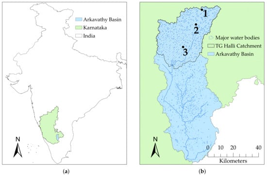
Figure 1.
This figure illustrates the geographic context of the study sites in this paper. (a) contains the location of the Arkavathy Basin in Karnataka, India, and (b) shows the location of TG Halli reservoir within the Arkavathy Basin, where the three study sites are located: (1) Hadonahalli tank (farthest upstream), (2) SM Gollahalli tank and (3) Nelamangala lake (farthest downstream). The direction of flow in this watershed is from North to South.
This watershed, like many in south India, is characterized by the presence of numerous (nearly 1700 in the Arkavathy watershed [28]) surface water harvesting and storage structures, known as “tanks”, that fragment the channel network. These historical in-channel tank structures provide an attractive target for understanding spatial change, as they are plentiful, many are large enough to observe in historical remote sensing records, and they are distributed broadly across the basin, allowing insight into different rates of change through space [28]. The tank structures are formed through the construction of earthen banks across natural landscape depressions to detain surface runoff. During the southeast (June–September) and northeast (October–December) monsoon seasons [29], the tanks catch and store monsoon runoff; in the dry seasons, storage levels drop due to groundwater recharge and evaporation. These seasonal and interannual dynamics are captured by changes in the surface area of the tanks from wet season to dry season, and from year to year. Yet translating observations of changes in tank surface area to a quantitive water budget also requires translating these surface area dynamics to volumetric measures—requiring tank bathymetry. Characterizing bathymetry across a representative set of tank structures, which can be inundated, largely dry, or incompletely wetted, depending on the time of the year, is non-trivial. The conventional surveying approach, which requires a total station, is expensive and time consuming. There is a need for low cost, rapid and extensible mapping techniques suitable to wet or dry conditions. Developing and testing such techniques is the focus of this paper.
To assess the potential for robot-assisted tank measurement by UAVs and USVs, two tanks (Hadonahalli and SM Gollahalli) and one lake (Nelamangala), were selected as study sites within the TG Halli sub-catchment. These three sites are spatially representative of the TG Halli catchment; it has been suggested that either eucalyptus plantations or groundwater depletion could be the drivers of streamflow decline within the TG Halli watershed [1]. The tanks selected have immediate upstream watersheds that contain a contrast between groundwater irrigated agriculture (more prominent in SM Gollahalli) and eucalyptus plantations (Hadonahalli). Additionally, large portions of the TG Halli watershed are urbanizing, especially near Bangalore and transportation networks. For this reason Nelamangala was also selected, which has a larger portion of urban land use than the other sites.
2.2. Tank Structures
Typical geometry and topography of the tank structures found in south India is shown in Figure 2. The tank bund is constructed adjacent to a depressional area in the landscape, which is referred to as the “immediate tank area”. The “tank spread area” is the flat region that extends past the main depression of the tank. Historically, sluice gates were constructed within the bund to control the release of water into irrigation channels [30,31]. At present, a majority of the tanks remain mostly dry [1,32] and water levels are rarely (if ever) elevated enough to completely fill the tank spread area or flow over the bund; however, the tank spread areas were measured in this study for completeness.

Figure 2.
Typical tank geometry, adapted from [31]. The tank initially fills in the immediate tank area, which is adjacent to the tank bund. The tank spread area extends beyond the main depression of the tank; this region is often farmed land and floods when water levels are elevated.
The tank boundaries used in this study were from a survey of the Arkavathy Basin conducted by the Karnataka State Remote Sensing Application Centre (KSRSAC). The boundary between the immediate tank area and the tank spread area was determined manually by observing the slope and topography within the tanks and delineating the deeper areas of higher slopes from the relatively flat, expansive area. The data collection and analyses procedure was the same for both the immediate and spread areas.
2.3. Robot-Assisted Data Collection
Due to monsoonal rainfall patterns, water status within the tanks may vary from full capacity to completely dry. UAV photogrammetry is an inexpensive and relatively accurate method to survey topography when the tanks are dry [33,34]; however, when the tanks are submerged, measurement using UAVs becomes futile. A data-fusion approach utilizing both UAVs and USVs enables year-round tank measurement, and a workflow for this approach is shown in Figure 3.
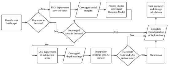
Figure 3.
Proposed workflow for collecting surface data using small robots, including UAVs and USVs, to fully characterize tanks and small reservoirs in various wet and dry conditions.
An Iris quadcopter (3D Robotics Inc., Berkeley, CA, USA—see Figure 4a) was flown to collect aerial imagery for topographic map generation. The Iris, equipped with 3DR uBlox GPS and 915 MHz radio telemetry, has up to a 1 km radio range and offers a 10 to 20-min flight time depending on payload. The maximum payload for this system is 425 g. A Sony ActionCam Mini (HDR-AZ1, Sony Corporation, Tokyo, Japan) was used for image acquisition. This camera has GPS logging capabilities and contains a 1/2.3 in-type Exmor R CMOS sensor with 11.9 MP effective pixels. The weight of the ActionCam Mini was only 63 g (including supplied NP-BY1 battery) and cost just under $400 USD. The ActionCam was attached to the UAV platform with a forward-facing mounting bracket angled at 60 from the horizontal to capture changes in elevation. The trajectory of each flight was carefully pre-planned using open-source ArduPilot Mission Planner software to ensure at least 60% side and 80% forward image overlap for optimum processing results [35]. The aerial images were used to generate 3D surface data using Agisoft PhotoScan Professional Edition photogrammetric processing software (v1.2.0, Agisoft LLC, St. Petersburg, Russia), with the following photo alignment parameters: Accuracy: high, Key Point Limit: 160,000, Tie Point Limit: 0 (no limit). With ‘high’ accuracy, Agisoft uses the full resolution photo. The Key Point Limit determines the number of points per photo; Tie Point Limit sets a limit on the number of points that tie one image to another.
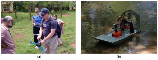
Figure 4.
(a) Demonstrating the 3DR Iris quadcopter near Bangalore (note: the sensor shown here mounted to the UAV is different from the Sony ActionCam used for data acquisition); (b) The custom USV airboat used for bathymetric data collection in the Arkavathy Basin.
In submerged areas of the tanks and in Lake Nelamangala, the custom USV airboat shown in Figure 4b was piloted manually at each site to collect bathymetric data. The USV is 0.5 m in length, can operate with up to a 2.25 kg payload, and has a 4-h continuous operation battery life, allowing for long range data collection deployments. A Spektrum DX8 Transmitter (Horizon Hobby, LLC, Champaign, IL, USA) was used with a Spektrum Receiver and Traxxas VXL-3S Brushless ECS (Traxxas, McKinney, TX, USA) to control the platform. To measure depth, a hand-held HawkEye sonar depth finder (H22PX, HawkEye Electronics, Orlando, FL, USA) was mounted to the USV. The HawkEye depth finder gives instantaneous depth readings within the approximate range of 0.75 to 30 m to the nearest 3.0 cm with ±5% accuracy. This instrument has a 30-h battery life and is ideal for continuous operation with the USV. The HawkEye depth finder does not have data-logging capabilities; therefore, to geotag the depth readings, the same GPS-enabled Sony ActionCam was mounted on the USV facing the depth finder to capture sonar readings at 2 s intervals. The USV was piloted manually and collected 30 data points per minute. After USV deployment, the sonar readings were recorded by hand from the images and matched to their corresponding GPS coordinates extracted from image EXIF data. The depth readings and coordinates were then exported into a shapefile data set and imported into ArcGIS 10.2 (Esri, Redlands, CA, USA) for further spatial analyses.
2.4. Tank Data-Fusion Processing and Calculations
The UAV and USV-generated surface data were merged to create a complete characterization of each tank. First, the geotagged USV depth readings were interpolated into a smooth raster surface using the spline method in ArcGIS. The spline method was preferred due to its capabilities of predicting ridges and valleys in the data, and to yield a surface that passes exactly through the measured input points [36]. To determine the boundary of interpolation, the extent of the water body was determined manually by observing the UAV-generated surface, which visibly captured the wetted area within the tank. By nature, this wetted area was as a flat region in the surface model, and the digital elevation model (DEM) values at this elevation were used to locate the extent of the wetted area.
Next, both surfaces were referenced to a common datum using water stage data measured at the time of deployment. The GPS location of the stage instrumentation in each tank was known, as well as the water level on the day of data collection. Therefore, a common point between the USV and UAV data sets could be used to match the surfaces. After properly referencing and matching the data, submerged areas on the UAV-generated surface were replaced by bathymetric data. For this step, it was important to ensure the spatial resolutions of the USV and UAV surfaces matched; this was achieved during the spatial interpolation step with the USV data. Additionally, the data processing occurred in identical coordinate systems and projections in ArcGIS to enable accurate data merging.
Before calculating surface geometries, areas of tree cover were filtered out. Relatively small, heavily vegetated areas within the tanks were located in the flat, expansive regions that extended past the deepest parts of the tank. These vegetated areas were leveled to an elevation value equal to the average of 20 points randomly sampled from a 1 m strip directly surrounding the vegetated region.
Tank geometry and storage capacity for each site were determined using the merged and leveled surfaces. Storage volumes were calculated for a range of water levels within the tank or lake from zero to the spillover elevation at which the tank overflows. To calculate storage volume for a given stage level, the quantity and elevation of all grid cells at or below the stage level were extracted and used in Equation (1) to calculate storage volume:
where is the total storage volume at stage level S (), is the area of the surface grid cells (), is the number of grid cells at level i, and is the elevation value of each cell at level i (m).
2.5. Validation of Topographic and Bathymetric Measurements
To ensure accuracy of the UAV measurements, validation bathymetry was measured for each immediate tank area. The validation data were manually collected by two persons in a boat when the tanks became fully submerged, taking depth readings approximately 5–10 m apart using the HawkEye depth finder. If the depth was greater than 75 cm (the minimum depth range of the sonar instrument), the GPS coordinates were marked and the depth was recorded. The operating depth range of the sonar instrumentation was only limiting very close to the tank edges where depth was occasionally less than 75 cm; therefore, if the sonar could not successfully make a depth reading near the tank edge, the instrument was moved away from that point until a reading could be made. Validation data was not collected for Nelamangala lake because uncertainty in the depth measurements was assumed to be inherent in the sonar instrumentation, which was .
The error was defined as the difference in elevation between the validation data and the robot-assisted data as described in Equation (2), and the error was calculated for each validation point i. The average absolute value of the error (), standard deviation of the error (), and the root mean square error () were calculated for each tank using Equations (3)–(5).
3. Field Investigations
3.1. UAV Deployments
Three team members previously untrained in robotics adopted the Shared Roles Model to enable successful UAV operation [37,38]. The team consisted of a Safety Officer, Mission Specialist, and Pilot. The Safety Officer was responsible for the overall safety of the team members and maintained awareness of the surrounding environmental and physical site conditions. The Mission Specialist monitored the real-time flight data, including battery life, ground speed, directional heading, and altitude, and assisted the Pilot with navigation. The Pilot was the member responsible for teleoperating the vehicle within line of sight and maintaining general airworthiness of the vehicle before, during, and after each flight.
The UAV was deployed at Hadonahalli and SM Gollahalli tanks to collect aerial images at a resolution of 1920 by 1080 pixels. At Hadonahalli tank, which was completely dry at the time of UAV deployment, a total of 6 flights captured 1122 images. The resulting DEM had a spatial resolution of 0.30 m. At SM Gollahalli tank, which at the time of flight was partially wetted, a total of 5 flights captured 1027 images suitable for analysis, resulting in a 0.23-m resolution DEM. Nelamangala lake was completely submerged; therefore, the UAV was not required at this location. Table 1 contains flight statistics for both sites, and Figure 5 contains sample images from the UAV surveys, illustrating the varying types of land cover and topography present within in the tanks.

Table 1.
Flight statistics at Hadonahalli and SM Gollahalli tanks. The UAV was set to a ground speed of 4 m/s for all flights. Images were considered “usable” if they were taken after the UAV hit the set altitude. Images recorded during takeoff and landing were discarded.
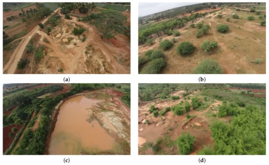
Figure 5.
Representative sample of tank aerial images: (a) immediate tank area of Hadonahalli where pockets and sharp changes in elevation were prevalent; (b) expansive, flat region surrounding the immediate tank in Hadonahalli (also referred to as the tank “spread area”); (c) submerged immediate tank area of SM Gollahalli; and (d) SM Gollahalli tank spread area.
The aerial photos were processed into 3D models using Agisoft PhotoScan Professional Edition, a commercially available photogrammetry software. PhotoScan has built-in functionalities to generate point clouds, dense clouds, and 3D surface reconstruction models. A top-down view of the Agisoft surface reconstructions for Hadonahalli and SM Gollahalli tank are shown in Figure 6, and were exported as GeoTIFF files for further ArcGIS processing (available as supplementary files Figures S1 and S2).
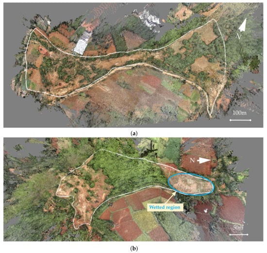
Figure 6.
3D surface reconstructions presented in Agisoft PhotoScan viewer for (a) Hadonahalli and (b) SM Gollahalli tanks. The white outline indicates the tank boundary, which is the overflow elevation. Data outside the boundaries were excluded. Hadonahalli tank was completely dry, while SM Gollahalli tank was partially wetted at the time of measurement. The water in the SM Gollahalli immediate tank area was highly turbid and appears brown in the surface reconstructions.
3.2. USV Deployments
The USV was used to collect bathymetric data in the submerged portion of SM Gollahalli tank and at Nelamangala lake. To deploy the USV, the platform was manually placed in the water near the shore and operated throughout the water body via remote control. A total of 373 data points were collected in 14 min at SM Gollahalli, covering an area of 850 m. At Nelamangala, flooded shorelines and thick aquatic vegetation imposed access difficulties for the USV; therefore, only a portion of the lake was investigated where the robot could be safely deployed, and the surface data and volume estimates were only evaluated for this portion of the lake. Two USV deployments were made in Nelamangala, collecting 816 depth readings in 28 min. The total area covered was approximately 8160 m2, and the resulting surface had a resolution of 0.234 m.
4. Results and Analyses
4.1. Tank Stage-Storage Relationship
Stage-storage relationships were calculated using the robot-assisted surface data and fit to a power law distribution. Nonlinear, and specifically power law type, distributions have been recognized as applicable models [39,40] and used in hydrologic modeling of small reservoirs [41,42] and storage-discharge and recharge relationships [43,44]. Figure 7 shows the stage-storage curves and power law fits for each site. The stage-storage relationships have been provided for stage levels ranging from zero to the spillover elevation in each tank (located at the top of the bund) for completeness; however, water levels are rarely (if ever) elevated enough to completely fill tank spread area, and at present a majority of the tanks remain mostly dry [1,32].
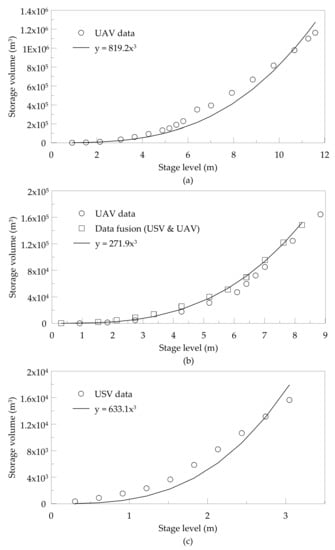
Figure 7.
Stage-storage relationships for: (a) Hadonahalli tank, (b) SM Gollahalli tank, including both UAV only and data fusion results, and (c) Nelamangala lake. In Figure (b), results from the UAV and USV data fusion approach (represented by squares) at SM Gollahalli tank yielded larger storage volumes compared to the data collected solely by the UAV (represented by circles). This is because tank topography in submerged areas cannot be captured with UAV imagery; supplemental measurements collected by the USV offer a more accurate representation of tank storage capacity.
4.2. Area-Storage Relationship
A common model for estimating small reservoir capacities uses the relationship where C is the capacity of a reservoir (m3), A is the surface area (m2), and a and b are calibration constants [42,45,46]. Storage-area relationships for Hadonahalli and SM Gollahalli are shown in Table 2, as well as the corresponding value. Figure 8 shows the area-storage relationship for the immediate tank area within SM Gollahalli and Hadonahalli. The tank spread area was not considered due a considerable difference in geometric properties compared to the immediate tank area. Differentiating this area from the immediate tank area is crucial when relating surface areas to volume, as there can be a very responsive change in surface areas for small changes in water depth in the spread region.

Table 2.
Area-storage relationships and the coefficient of determination () values for each curve fit. C is the tank capacity (m3), A is the tank surface area (m2), and a, b are calibration constants.
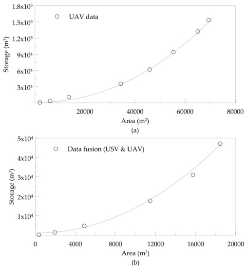
Figure 8.
Area-storage relationships for (a) Hadonahalli tank and (b) data-fusion data from SM Gollahalli tank. Area-storage data are plotted against the curve fit presented in Table 2.
As a simple example of the hydrologic use of the bathymetric data, a suite of timeseries is presented for Hadonahalli tank in Figure 9. With tank bathymetry available, timeseries of stage fluctuations can be converted into volumetric fluctuations, from which the net seasonal inflow volumes to the tank can be inferred. The water level is the calibrated stage from an Odyssey capacitive water level logger (Dataflow Systems Ltd., Christchurch, New Zealand). Water level is mapped to water storage using the stage-volume relationship obtained from the robot-assisted data, and daily inflow is calculated as the change in storage from one day to the next. Since non-overflowing tanks act as terminal reservoirs along sections of the river network, these tank inflows provide insight into volumes that are prevented from reaching downstream parts of the network, while the peak volumetric storage (also available from the bathymetry) acts as a key hydrologic threshold needed to achieve connectivity between TG Halli milliwatershed and the remainder of the Arkavathy Basin.
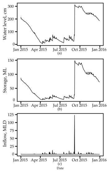
Figure 9.
Water in Hadonahalli tank in 2015, including (a) water level; (b) water storage (millions of liters); and (c) daily inflow (millions of liters per day). Note: days without inflow (and therefore a negative change in storage due to groundwater recharge and evaporative losses) were set to zero for the daily inflow plot.
4.3. Validation of Robot-Assisted Measurements
A total of 105 and 72 validation points were measured at Hadonahalli and SM Gollahalli tanks, respectively. The validation method described in Section 2.4 was applied to the surface data. Summary statistics for the error, measured as the difference between the validation points and the robot-assisted data, are shown in Table 3. Using the mean absolute elevation error, the total error in the volume estimation for each tank is also presented in percentage of total tank capacity.

Table 3.
Summary statistics for the elevation error measurements and the volume estimation error for Hadonahalli and SM Gollahalli tanks.
The average absolute error for Hadonahalli and SM Gollahalli tanks are 0.833 and 0.617 m, respectively. These results are in agreement with other studies that produced digital elevation models of terrain data from UAV aerial images [33,34]. The Root Mean Square Error (RMSE) was calculated for each tank, which is a measure of dispersion of the distribution of deviations between the estimated elevation data (robot-assisted measurements) and the validation data. The RMSE for Hadonahalli tank is 1.13 m, and for SM Gollahalli tank is 0.862 m. The total error in tank volume estimation is 14.5% for Hadonahalli tank and 14.9% for SM Gollahalli tank.
The error values were also compared to terrain slope at each validation point to determine if a correlation exists between error and slope within the tank (see Figure 10). Histograms of the error were also created for each tank. No significant correlation was found between terrain slope and error; the R-squared values were for Hadonahalli and for SM Gollahalli tank, respectively. Also, it can be seen from the error histograms that the highest frequency of values occurs at m for each data set.
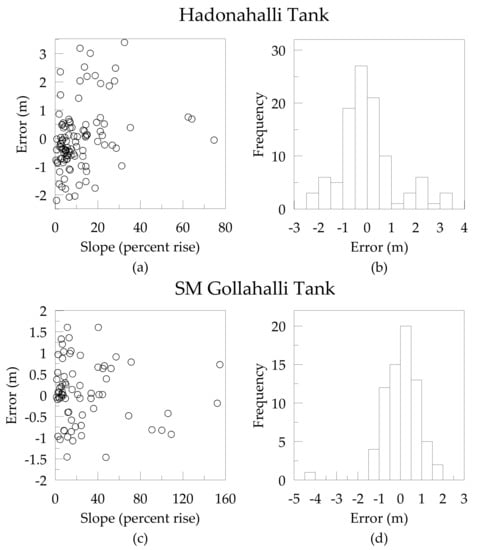
Figure 10.
(a,c) show the error of each validation point plotted against the terrain slope (in percent rise) for each tank. (b,d) are histograms of the elevation error for 72 validation data points at SM Gollahalli tank and 105 validation points Hadonahalli tank. Bin widths of 0.5 m were used for each tank.
The average absolute error was also compared for surface data collected from only the UAV versus the USV. Because SM Gollahalli tank was the only partially-wetted site for which the UAV and USV data were fused, this comparison was performed only for that tank. The average absolute error is 0.613 m for validation data points that were measured in locations corresponding to UAV-only data. For USV surface data, the average absolute error is 0.628 m.
From these analyses, it is evident that elevation error is consistent across varying tank topographies, as there is no correlation between slope and error. Overall volume estimation accuracy of approximately 86% and average errors of less than 1 m constitute this as a low-cost, expeditious method for measuring tank geometry and storage capacities in data-sparse regions. Also, the average absolute errors are similar for surface data collected by each robot platform at SM Gollahalli tank, and because the general shapes of each tank are fairly homogeneous, this is likely to be the case for other tanks as well. Therefore, it is suggested that this method can be used year-round in varying proportions of wet and dry areas of the tanks without compromising accuracy.
5. Discussion
5.1. Viability of Small Robots for Surface Data Collection
A human-robot team including UAVs and USVs is a reproducible and economical method capable of yielding surface data at high spatial and temporal resolutions. The use of small robots can be compared to current measurement approaches in three specific domains: (i) spatial resolution of the resulting data; (ii) temporal resolution of data capture; and (iii) economics of the cost per unit area (see Figure 11). Spatial resolution is the smallest basic unit in an image or elevation model, and smaller units indicate higher resolutions. Temporal resolution is the time between data capture for the same location; therefore, higher capture rates are preferred [47]. The ideal case when considering each of these three dimensions is located in close proximity to the origin.
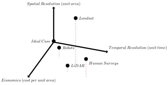
Figure 11.
A comparison of small robots (UAVs and USVs) against LiDAR, human surveys, Landsat imagery, and the ideal case over three domains: (i) spatial resolution of data; (ii) temporal resolution of collection; and (iii) cost per unit area. The ideal case represents the highest temporal and spatial resolution at no cost. LiDAR data has high spatial resolution, but collection is expensive and infrequent. Landsat imagery, typically captured bi-monthly, has 15–30 m spatial resolution. While inefficient, spatial resolution of human surveys increases with additional time and personnel.
One available source of surface data for the Arkavathy region is Landsat imagery, which is available dating back to the early 1970s. The 30-m resolution of Landsat data provides coarser estimates of water surface area in small tanks, with concerns of misclassification pixels at the edges of tanks and greater potential for error in estimating surface area in small tanks. Pixels at or near tank edges may be incorrectly classified as either water or soil, with the consequence of over or underestimating tank surface area [42] (although spectral unmixing approaches offer a viable approach to improve this classification [28]). Grid cell size of the robot-assisted elevation models in this study ranged from 0.23 m to 0.30 m, improving the resolution of the data to meet the needs of small-scale basin analysis. Robot-assisted measurements of lake bathymetry at high resolution have the potential for greatly extending the utility of estimates of lake water surface area (e.g., from Landsat) by allowing conversion of water surface area to stored water volumes.
Deployment of small robots requires less time, equipment, and labor compared to traditional surveying techniques. Topographic surveys at relatively small sites require a large suite of manually operated, terrestrial survey equipment; a standard crew of 2 men needs a total station, data collector, tripods, tribrachs, target carriers, range poles, plane tables, and GPS receivers [48]. For a 2–3 person crew, transportation and handling of unwieldy surveying equipment is laborious compared to the single case and laptop required for UAV deployment. Prior to this field study, tank bathymetry in the Arkavathy was measured manually by two persons from a boat using hand held instrumentation. The manual validation bathymetry survey of SM Gollahalli tank collected 72 data points in 2 h, and required additional post-processing surface contouring analyses. In contrast, the USV deployment autonomously collected 816 data points in 28 min, resulting in over 5 times the amount of data collected in one fourth the time. One limitation of the USV was the need to manually record sonar readings from video and images captured on board. For this study, the USV was deployed at only two sites and this step did not hinder the overall data flow; however, automating the data logging in the future would improve the overall efficiency of this method, especially if many sites are surveyed.
Utilizing inexpensive, lightweight off-the-shelf cameras and sensors offers an economic advantage for surface mapping and improves the accessibility of this method for data-sparse regions. The Sony ActionCam used in this study weighed only 120 g and cost around $400 USD. While the ActionCam and other cameras are highly suitable for use with quadrotor UAVs, recent advances in rangefinding sensors such as LiDAR have made them competitively lightweight and affordable. Recent studies have used low-altitude long-endurance (LALE) category UAVs to mount commercial off-the-shelf rangefinding components [49,50]. Although these sensors are substantially smaller and less expensive than previous generation sensors, they can still cost thousands of dollars (e.g., $8000 for the Velodyne LiDAR Puck LITE). LiDAR sensors also typically require on-board power supply and can weigh between 0.6 and 2 kg, which can severely shorten the total flight time of a quadrotor. Also, the possibility of losing a small UAV aircraft in challenging conditions must not be ignored; the financial risk is much greater if the UAV is equipped with expensive rangefinding sensors compared to standard digital cameras [33,34].
5.2. Informing Hydrologic Analyses in the Arkavathy Basin
High-resolution surface data collected from three new field investigations enabled geometry and capacity calculations that informs hydrologic analyses for the Arkavathy Basin by defining power-type stage-volume and stage-surface area relationships. These relationships can then be be converted into volumetric fluctuations, from which the net seasonal inflow volumes to the tank can be inferred. The close connection of the tanks in this region to surface water hydrology, due to their original construction as rainfall harvesting structures, yield a finer resolution of understanding of the hydrological processes in the Arkavathy.
Since the 1960s, continual agricultural-related groundwater depletion in Southern India has led to the conversion of many existing tanks into infiltration basins with the intention of recharging groundwater supplies [51,52]. The tanks now primarily function as terminal basins that rarely overflow due to decreased flow; therefore, fluctuations in tank depth serve as a proxy for upstream flow contributions, and tank inflows provide insight into volumes that are prevented from reaching downstream parts of the network. A water balance can then be used to evaluate potential causes for the drying of the Arkavathy Basin:
where S is the total volume of water stored in the catchment, P is precipitation, A is irrigation use, drawn from either groundwater or tank water, E is evapotranspiration, L is leakage from surface catchment to deep aquifers, and Q streamflow partitioned into two components: is a baseflow component, and is quickflow generated by surface processes. Quantifying Q is critically important for understanding rainfall-runoff processes at multiple time scales, but it remains largely unknown up to this point. However, this study enables the determination of Q near these field sites, given that the tank depth sensors have been in place for over two years.
This water balance approach is currently being used to understand the local hydrological responses to rainfall production in target watersheds, based on depth-gaging of the terminal tanks. Completing water balance analyses for these watersheds requires developing high-resolution bathymetric maps of the tanks. The robot-assisted measurements in this study perform a critical function in understanding flow generation processes in this rapidly changing watershed, and the development of this methodology has begun laying the groundwork for understanding the water balance of larger watersheds within the region. The stage-storage and storage-surface area relationships found in this study also provide data that directly contributes to the water balance of the Arkavathy Basin by also informing measurement of both the E and L terms.
Measured tank geometry from this study may also be used to understand the geometry and storage-surface area relationships of other tanks in the watershed. The surface area of small reservoirs has been found to correlate well with storage volume, using the relationship [42,53,54]. Preliminary analysis indicates that a strong power-type relationship does exist between surface area and storage volume. To date, analyses have focused on surface area trends in tanks across the Arkavathy Basin, but the results may be biased in important ways (e.g., over- or under-estimation of the magnitude of these trends) because of the nonlinear relationship between flow volumes (the conserved quantity that is changing) and surface areas (that can be observed). Correcting for this nonlinearity at representative tanks across the Arkavathy Basin could improve understanding of change in this otherwise poorly monitored basin.
A formative observation can be made that quantifying tank storage enables better evaluation of the risks and benefits of local tank water supplies for agriculture. By the late 20th Century, groundwater pumping had almost entirely displaced tank irrigation in supporting irrigated agriculture in the Arkavathy Basin [30,55]. Yet the tank infrastructure network remains in place, and continues to store water. In the context of ongoing drying within the Arkavathy Basin, understanding the magnitude of this water source, along with the long term trends and interannual variability associated with these sources, could provide important context for local water resources planning. At present, indicative measures of this variability can be obtained from aerial photography and satellite measurements, and the value of these observations would increase dramatically if surface area observations could be related to volumes. Similarly, important tradeoffs associated with utilization of the tank water supply, which range from the timing of water availability to the partitioning of tank water between groundwater recharge and evapotranspiration, can only be meaningfully evaluated with information about storage geometry.
6. Conclusions
To summarize, this work determined that deploying a heterogeneous team of small robots including UAVs and USVs is a low-cost method for collecting tank surface data, which can be used to elucidate hydrologic understanding in a data-sparse, highly impacted human watershed. The transport, management, and storage of the unmanned systems and their data are low-effort and suitable for high temporal frequency deployments in rural, data-sparse areas. Surface data collected from three field study sites provides stage-storage and stage-surface area relationships, which will provide a finer resolution estimation of tank evaporation and leakage potential, and can serve as a proxy for upstream flow contributions. Knowing the amount of water available in the tanks year-round by relating stage levels to storage volume enables more informed decisions and recommendations regarding water resource planning and management.
Spatial and temporal resolution of remotely-sensed surface data can be increased in an economically viable way through the use of small UAVs and USVs. Cost of high-resolution automated data collection in developing data-sparse regions may be a barrier to acquisition due to financial and infrastructure constraints, but this can be overcome through the use of low-cost robotics technologies. This is especially important for ad hoc human-robot teams where users will likely not have regular training and exposure to small UAV and USV technology. An additional consequence of ease of use is that the adoption rate of small UAV and USV technology by researchers, practitioners, and citizen scientists may increase in developing regions as currently many do not utilize these kinds of technologies.
New high-resolution elevation models were created for three previously unmapped field sites within the Arkavathy Basin and were used to create hydrologic capacity curves. The capacity data for Hadonahalli tank were used to create a timeseries of stage and volumetric fluctuations, from which net seasonal inflow volumes can be inferred. Establishing a corpus of data for testing flow decline hypotheses in the Arkavathy, such as tank storage volumes or inflows, reduces confounding variables in conceptual understanding and hydrologic modeling that arise due to data scarcity. This is important for local hydrologic researchers and modelers who, in the absence of high-resolution tank data, are otherwise forced to make simplifying assumptions.
This research suggests that more work is needed to fully understand the storage potential of all tanks in the Arkavathy Basin. Now that a robot-assisted methodology has been developed and tested for high-resolution tank measurement, more complete, long-term studies are recommended to survey a greater number of tanks for basin-scale hydrologic modeling. Additionally, it is recommended a targeted study be conducted to better understand the mechanisms for supplementing groundwater irrigation sources with surface water. In particular, surface sources incur lower investment costs, lower pumping costs, and reduced uncertainty in terms of failure; however, disadvantages include potentially decentralized locations of tanks, rainfall variability, and/or legal issues regarding withdrawals. Understanding these issues in the context of the Arkavathy Basin are important for effective agricultural resource planning and management decisions.
Supplementary Materials
The following are available online at www.mdpi.com/2073-4441/9/7/494/s1, Figure S1: GeoTIFF file of Hadonahalli tank as exported from Agisoft Photoscan, Figure S2: GeoTIFF file of SM Gollahalli tank as exported from Agisoft Photoscan.
Acknowledgments
This material is based upon work supported by NSF CNIC 1427420: US-India Collaborative Research Linking Remote Sensing, Citizen Science, and Robotics to Address Critical Environmental Problems in Data Sparse Regions. The authors would like to thank the ATREE’s EcoInformatics Lab for RS/GIS support, H. Usha for administrative support, K. Janardhan and G. Manjunath for community outreach efforts, and C. Varan for field research support. Funding for ATREE’s Arkavathy Basin research was from Grant No. 107086-001 from the International Development Research Centre (IDRC), Canada. Young acknowledges Government support under and awarded by DoD, Air Force Office of Scientific Research, National Defense Science and Engineering Graduate (NDSEG) Fellowship, 32 CFR 168a. Penny acknowledges support from the NSF Graduate Research Fellowship Program under Grant No. DGE 1106400, and the NSF and USAID GROW Fellowship Program.
Author Contributions
Joshua Peschel, Sally Thompson, and Veena Srinivasan conceived and designed the field studies; Sierra Young and Gopal Penny performed the field studies; Sierra Young and Joshua Peschel analyzed the data; Veena Srinivasan contributed materials and analysis tools; Sierra Young and Joshua Peschel wrote the paper.
Conflicts of Interest
The authors declare no conflict of interest.
References
- Srinivasan, V.; Thompson, S.; Madhyastha, K.; Penny, G.; Jeremiah, K.; Lele, S. Why is the Arkavathy River drying? A multiple-hypothesis approach in a data-scarce region. Hydrol. Earth Syst. Sci. 2015, 19, 1905–1917. [Google Scholar] [CrossRef]
- Beniston, M.; Stoffel, M.; Harding, R.; Kernan, M.; Ludwig, R.; Moors, E.; Samuels, P.; Tockner, K. Obstacles to data access for research related to climate and water: Implications for science and EU policy-making. Environ. Sci. Policy 2012, 17, 41–48. [Google Scholar] [CrossRef]
- Thompson, S.; Sivapalan, M.; Harman, C.J.; Srinivasan, V.; Hipsey, M.; Reed, P.; Montanari, A.; Blöschl, G. Developing predictive insight into changing water systems: Use-inspired hydrologic science for the Anthropocene. Hydrol. Earth Syst. Sci. 2013, 17, 5013–5039. [Google Scholar] [CrossRef]
- Sivapalan, M.; Savenije, H.H.G.; Blöschl, G. Socio–hydrology: A new science of people and water. Hydrol. Process. 2012, 26, 1270–1276. [Google Scholar] [CrossRef]
- Roy, H.E.; Pocock, M.J.; Preston, C.D.; Roy, D.B.; Savage, J.; Tweddle, J.; Robinson, L. Understanding Citizen Science and Environmental Monitoring: Final Report on Behalf of UK Environmental Observation Framework; NERC/Centre for Ecology & Hydrology: Swindon, UK, 2012. [Google Scholar]
- Ping, J.T.K.; Ling, A.E.; Quan, T.J.; Dat, C.Y. Generic unmanned aerial vehicle (UAV) for civilian application-A feasibility assessment and market survey on civilian application for aerial imaging. In Proceedings of the 2012 IEEE Conference on Sustainable Utilization and Development in Engineering and Technology, Kuala Lumpur, Malaysia, 6–9 October 2012; pp. 289–294. [Google Scholar]
- Peschel, J.; Murphy, R. On the human-machine interaction of unmanned aerial system mission Specialists. IEEE Trans. Hum.-Mach. Syst. 2013, 43, 53–62. [Google Scholar] [CrossRef]
- Mancini, A.; Dubbini, M.; Gattelli, M.; Stecchi, F.; Fabbri, S.; Gabbianelli, G. Using unmanned aerial vehicles (UAV) for high-resolution reconstruction of topography: The structure from motion approach on coastal environments. Remote Sens. 2013, 5, 6880–6898. [Google Scholar] [CrossRef]
- Tonkin, T.N.; Midgley, N.G.; Graham, D.J.; Labadz, J.C. The potential of small unmanned aircraft systems and structure-from-motion for topographic surveys: A test of emerging integrated approaches at Cwm Idwal, North Wales. Geomorphology 2014, 226, 35–43. [Google Scholar] [CrossRef]
- Flynn, K.; Chapra, S. Remote sensing of submerged aquatic vegetation in a shallow non-turbid river using an unmanned aerial vehicle. Remote Sens. 2014, 6, 12815–12836. [Google Scholar] [CrossRef]
- Gómez-Candón, D.; Castro, A.; López-Granados, F. Assessing the accuracy of mosaics from unmanned aerial vehicle (UAV) imagery for precision agriculture purposes in wheat. Precis. Agric. 2014, 15, 44–56. [Google Scholar] [CrossRef]
- Salami, E.; Barrado, C.; Pastor, E. UAV flight experiments applied to the remote sensing of vegetated areas. Remote Sens. 2014, 6, 11051–11081. [Google Scholar] [CrossRef]
- Goodrich, M.A.; Morse, B.S.; Engh, C.; Cooper, J.L.; Adams, J.A. Towards using unmanned aerial vehicles (UAVs) in wilderness search and rescue: Lessons from field trials. Interact. Stud. 2009, 10, 453–478. [Google Scholar]
- Tauro, F.; Porfiri, M.; Grimaldi, S. Surface flow measurements from drones. J. Hydrol. 2016, 540, 240–245. [Google Scholar] [CrossRef]
- Warner, T.; Nellis, D.; Foody, G. Optical Sensor Technology. In The SAGE Handbook of Remote Sensing; SAGE: Thousand Oaks, CA, USA, 2009; pp. 95–107. [Google Scholar]
- Harriott, C.E.; Adams, J.A. Modeling human performance for human–robot systems. Rev. Hum. Factors Ergon. 2013, 9, 94–130. [Google Scholar] [CrossRef]
- DeBell, L.; Anderson, K.; Brazier, R.E.; King, N.; Jones, L. Water resource management at catchment scales using lightweight UAVs: Current capabilities and future perspectives. J. Unmanned Veh. Syst. 2015, 4, 7–30. [Google Scholar] [CrossRef]
- Ouédraogo, M.M.; Degré, A.; Debouche, C.; Lisein, J. The evaluation of unmanned aerial system-based photogrammetry and terrestrial laser scanning to generate DEMs of agricultural watersheds. Geomorphology 2014, 214, 339–355. [Google Scholar] [CrossRef]
- Notebaert, B.; Verstraeten, G.; Govers, G.; Poesen, J. Qualitative and quantitative applications of LiDAR imagery in fluvial geomorphology. Earth Surf. Process. Landf. 2009, 34, 217–231. [Google Scholar] [CrossRef]
- Kitts, C.; Mahacek, P.; Adamek, T.; Rasal, K.; Howard, V.; Li, S.; Badaoui, A.; Kirkwood, W.; Wheat, G.; Hulme, S. Field operation of a robotic small waterplane area twin hull boat for shallow-water bathymetric characterization. J. Field Robot. 2012, 29, 924–938. [Google Scholar] [CrossRef]
- Vaneck, T.W.; Rodriguez-Ortiz, C.D.; Schmidt, M.C.; Manley, J.E. Automated bathymetry using an autonomous surface craft. Navigation 1997, 43, 407–418. [Google Scholar] [CrossRef]
- Yaakob, O.; Mohamed, Z.; Hanafiah, M.S.; Suprayogi, D.; Abdul Ghani, M.; Adnan, F.; Mukti, M.; Din, J. Development of unmanned surface vehicle (USV) for sea patrol and environmental monitoring. In Proceedings of the International Conference on Marine Technology, Kuala Terengganu, Malaysia, 20–22 October 2012. [Google Scholar]
- Casper, A.F.; Hall, M.L.; Dixon, B.; Steimle, E.T. Combining data collection from unmanned surface vehicles with geospatial analysis: Tools for improving surface water sampling, monitoring, and assessment. In Proceedings of the OCEANS 2007, Vancouver, BC, Canada, 29 September–4 October 2007; pp. 1–6. [Google Scholar]
- Legleiter, C.J. Remote measurement of river morphology via fusion of LiDAR topography and spectrally based bathymetry. Earth Surf. Process. Landf. 2012, 37, 499–518. [Google Scholar] [CrossRef]
- Flener, C.; Vaaja, M.; Jaakkola, A.; Krooks, A.; Kaartinen, H.; Kukko, A.; Kasvi, E.; Hyyppä, H.; Hyyppä, J.; Alho, P. Seamless mapping of river channels at high resolution using mobile LiDAR and UAV-photography. Remote Sens. 2013, 5, 6382–6407. [Google Scholar] [CrossRef]
- Manley, J.E. Unmanned surface vehicles, 15 years of development. In Proceedings of the OCEANS 2008, Quebec, QC, Canada, 15–18 September 2008; pp. 1–4. [Google Scholar]
- The Navy Unmanned Surface Vehicle (USV) Master Plan; Technical Report; United States Department of the Navy: Washington, DC, USA, 2007.
- Penny, G.; Srinivasan, V.; Dronova, I.; Lele, S.; Thompson, S. Spatial characterization of long-term hydrological change in the Arkavathy watershed adjacent to Bangalore, India. Hydrol. Earth Syst. Sci. Discuss. 2016. [Google Scholar] [CrossRef]
- Reduced Inflow into Tippagondanahalli Reservoir (TGR): A Remote Sensing Based Evaluation; Technical Report; ISRO (Indian Space Research Organization) IN-RIMT (Indian Resources Information & Management Technologies Pvt. Ltd): Bangalore, India, 2000.
- Van Meter, K.J.; Basu, N.B.; Tate, E.; Wyckoff, J. Monsoon harvests: The living legacies of rainwater harvesting systems in South India. Environ. Sci. Technol. 2014, 48, 4217–4225. [Google Scholar] [CrossRef] [PubMed]
- Van Meter, K.J.; Steiff, M.; McLaughlin, D.L.; Basu, N.B. The socioecohydrology of rainwater harvesting in India: Understanding water storage and release dynamics across spatial scales. Hydrol. Earth Syst. Sci. 2016, 20, 2629–2647. [Google Scholar] [CrossRef]
- Lele, S.; Srinivasan, V.; Jamwal, P.; Thomas, B.K.; Eswar, M.; Zuhail, T.M. Water Management in Arkavathy Basin: A Situation Analysis; Ashoka Trust for Research in Ecology and the Environment: Bangalore, India, 2013. [Google Scholar]
- Kršák, B.; Blištan, P.; Pauliková, A.; Puškárová, P.; Kovanic, L.; Palková, J.; Zeliznaková, V. Use of low-cost UAV photogrammetry to analyze the accuracy of a digital elevation model in a case study. Measurement 2016, 91, 276–287. [Google Scholar] [CrossRef]
- Hsieh, Y.C.; Chan, Y.C.; Hu, J.C. Digital elevation model differencing and error estimation from multiple sources: A case study from the Meiyuan Shan Landslide in Taiwan. Remote Sens. 2016, 8, 199. [Google Scholar] [CrossRef]
- Agisoft PhotoScan User Manual: Professional Edition; Version 1.2; Agisoft LLC: St. Petersburg, Russia, 2016.
- Childs, C. Interpolating surfaces in ArcGIS spatial analyst. ArcUser 2004, 3235, 32–35. [Google Scholar]
- Peschel, J. Mission Specialist Human-Robot Interaction in Micro Unmanned Aerial Systems. Ph.D. Thesis, Texas A&M University, College Station, TX, USA, 2012. [Google Scholar]
- Murphy, R.; Pratt, K.; Burke, J. Crew roles and operational protocols for rotary-wing micro-UAVs in close urban environments. In Proceedings of the Third ACM/IEEE International Conference on Human-Robot Interaction, Amsterdam, The Netherlands, 12–15 March 2008; pp. 73–80. [Google Scholar]
- Amorocho, J. Measures of the linearity of hydrologic systems. J. Geophys. Res. 1963, 68, 2237–2249. [Google Scholar] [CrossRef]
- Brutsaert, W. Water on the land surface: Fluid mechanics of free surface flow. In Hydrology: An Introduction; Cambridge University Press: Cambridge, UK, 2005. [Google Scholar]
- Moore, R. Storage-outflow modelling of streamflow recessions, with application to a shallow-soil forested catchment. J. Hydrol. 1997, 198, 260–270. [Google Scholar] [CrossRef]
- Sawunyama, T.; Senzanje, A.; Mhizha, A. Estimation of small reservoir storage capacities in Limpopo River Basin using geographical information systems (GIS) and remotely sensed surface areas: Case of Mzingwane catchment. Phys. Chem. Earth 2006, 31, 935–943. [Google Scholar] [CrossRef]
- Wittenberg, H. Baseflow recession and recharge as nonlinear storage processes. Hydrol. Process. 1999, 13, 715–726. [Google Scholar] [CrossRef]
- Botter, G.; Porporato, A.; Rodriguez-Iturbe, I.; Rinaldo, A. Nonlinear storage–discharge relations and catchment streamflow regimes. Water Resour. Res. 2009, 45. [Google Scholar] [CrossRef]
- Liebe, J. Estimation of Water Storage Capacity and Evaporation Losses of Small Reservoirs in the Upper East Region of Ghana. Ph.D. Thesis, Bonn University, Bonn, Germany, 2002. [Google Scholar]
- Meigh, J. The impact of small farm reservoirs on urban water supplies in Botswana. Nat. Resour. Forum 1995, 19, 71–83. [Google Scholar] [CrossRef]
- Théau, J. Temporal resolution. In Encyclopedia of GIS; Springer International Publishing: Cham, Switzerland, 2008; pp. 1150–1151. [Google Scholar]
- US Army Corps of Engineers. Chapter 2: Overview of topographic surveying techniques and methods. In Control and Topographic Surveying Engineer Manual; Department of the Army: Washington, DC, USA, 2007; pp. 1–38. [Google Scholar]
- Crocker, I.; Maslanik, J.A.; Adler, J.J.; Palo, S.E.; Herzfeld, U.C.; Emery, W.J. A sensor package for ice surface observations using small unmanned aircraft systems. IEEE Trans. Geosci. Remote Sens. 2012, 50, 1033–1047. [Google Scholar] [CrossRef]
- Pires, A.; Chaminé, H.I.; Nunes, J.C.; Borges, P.A.; Garcia, A.; Sarmento, E.; Antunes, M.; Salvado, F.; Rocha, F. New mapping techniques on coastal volcanic rock platforms using UAV LiDAR surveys in Pico Island, Azores (Portugal). In Volcanic Rocks and Soils; CRC Press: Boca Raton, FL, USA, 2015; pp. 385–388. [Google Scholar]
- Glendenning, C.J.; Vervoort, R. Rainwater Harvesting—A Supply-Side Management Tool for Sustaining Groundwater in India. In Sustainable Water Use and Management; Green Energy and Technology, Springer International Publishing: Cham, Switzerland, 2014; pp. 313–337. [Google Scholar]
- Palanisami, K.; Meinzen-Dick, R.; Giordano, M. Climate change and water supplies: Options for sustaining tank irrigation potential in India. Econ. Political Wkly. 2010, 45, 183–190. [Google Scholar]
- Perrin, J.; Ferrant, S.; Massuel, S.; Dewandel, B.; Maréchal, J.C.; Aulong, S.; Ahmed, S. Assessing water availability in a semi-arid watershed of southern India using a semi-distributed model. J. Hydrol. 2012, 460, 143–155. [Google Scholar] [CrossRef]
- Rodrigues, L.; Sano, E.E.; Steenhuis, T.S.; Passo, D.P. Estimation of small reservoir storage capacities with remote sensing in the Brazilian Savannah Region. Water Resour. Manag. 2012, 26, 873–882. [Google Scholar] [CrossRef]
- D’Souza, R. Water in British India: The making of a “colonial hydrology”. Hist. Compass 2006, 4, 621–629. [Google Scholar] [CrossRef]
© 2017 by the authors. Licensee MDPI, Basel, Switzerland. This article is an open access article distributed under the terms and conditions of the Creative Commons Attribution (CC BY) license (http://creativecommons.org/licenses/by/4.0/).