1. Introduction
In 2015, the Korea Radioactive Waste Agency at the Gyeongju nuclear waste facility started the first-stage of low- and intermediate-level radioactive waste disposal in a cavern at a depth of 130 m below the ground surface, and it is currently undergoing the process to gain permission from the regulatory agency in order to build a second-stage near-surface disposal facility. The Gyeongju radioactive waste disposal facility is equipped with a multi-barrier system consisting of a primary engineered barrier and secondary natural barrier in order to safely isolate nuclear waste from human exposure. The natural barrier functions to reduce the risk of radionuclide leakage from the disposal facility by adsorbing the radionuclides as well as impeding their movement, as the radionuclides predominately migrate along groundwater flow paths if the engineering barrier is damaged.
Radionuclide migration paths are intimately linked to discrete fracture networks that are characterized by heterogeneous fracture orientations, densities and sizes. Over the past several decades, the discrete fracture network (DFN) model has been utilized to characterize natural discrete fracture networks in relation to nuclear facilities [
1,
2,
3], underground petroleum-storage systems [
4,
5], and enhanced geothermal systems [
6,
7]. The DFN model can simulate 2- or 3-dimensional networks of discrete features governing flow and transport, as well as partial or complete flow barriers or conductors (e.g., faults and argillaceous layers). It more accurately simulates the hydrodynamic behavior of fluids in fractured rocks by characterizing the distribution of faults and fractures [
1,
5,
8]. DFN simulation successfully models this flow behavior by considering the connectivity, anisotropy, clusters and heterogeneity of the fractured rocks [
9,
10]. Swedish [
11] and Finnish [
12] regulating agencies have approved repository sites of high-level nuclear waste based on the evaluation of nuclide transport by using the DFN approach. A DFN generated using the feature rejection algorithm was used for simulating subsurface flow and transport [
13]. Fractal DFN models were developed to simulate naturally fractured reservoirs with fracture fractal properties of aperture, spacing, and length distribution [
14,
15,
16]. Hydraulic heterogeneity of fractured rock has been addressed by means of upscaling analysis of classical fracture networks or enhanced stochastic continuum approaches [
17].
Conventional DFN modeling approaches have been widely applied to analyze groundwater flow and solute transport through highly heterogeneous fractured rock, as mentioned above [
2,
11,
12,
18,
19]. In these previous studies, DFN parameters (size, orientation, intensity) were determined as statistical distributions obtained mainly from local data such as BHTV (borehole televiewer), geophysical logging, and fracture traces in tunnels/outcrops. When these locally determined DFN parameters are applied to a large-scale model (>1 km), heterogeneity of the fractured rock cannot be represented properly because the regional fracture heterogeneity cannot be controlled by using only locally determined parameters. Furthermore, fracture hydraulic properties (e.g., transmissivity, hydraulic conductivity) were assigned without taking into account fracture size and connectivity with other fractures. For more reliable site-scale or full-field DFN modeling, incorporation of the following two subjects is required: (i) representation of regional fracture heterogeneity; and (ii) connectivity of conductive fractures.
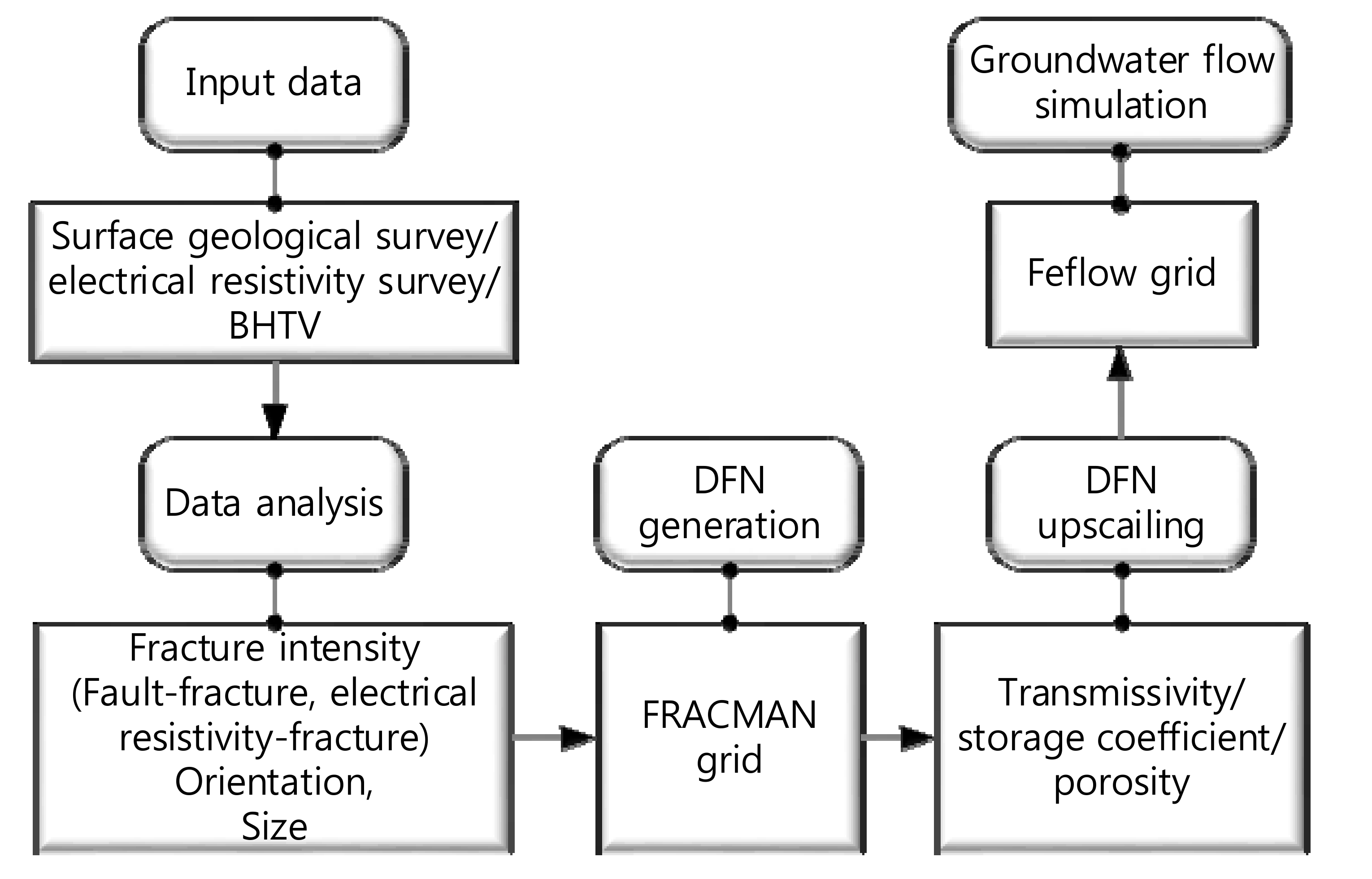
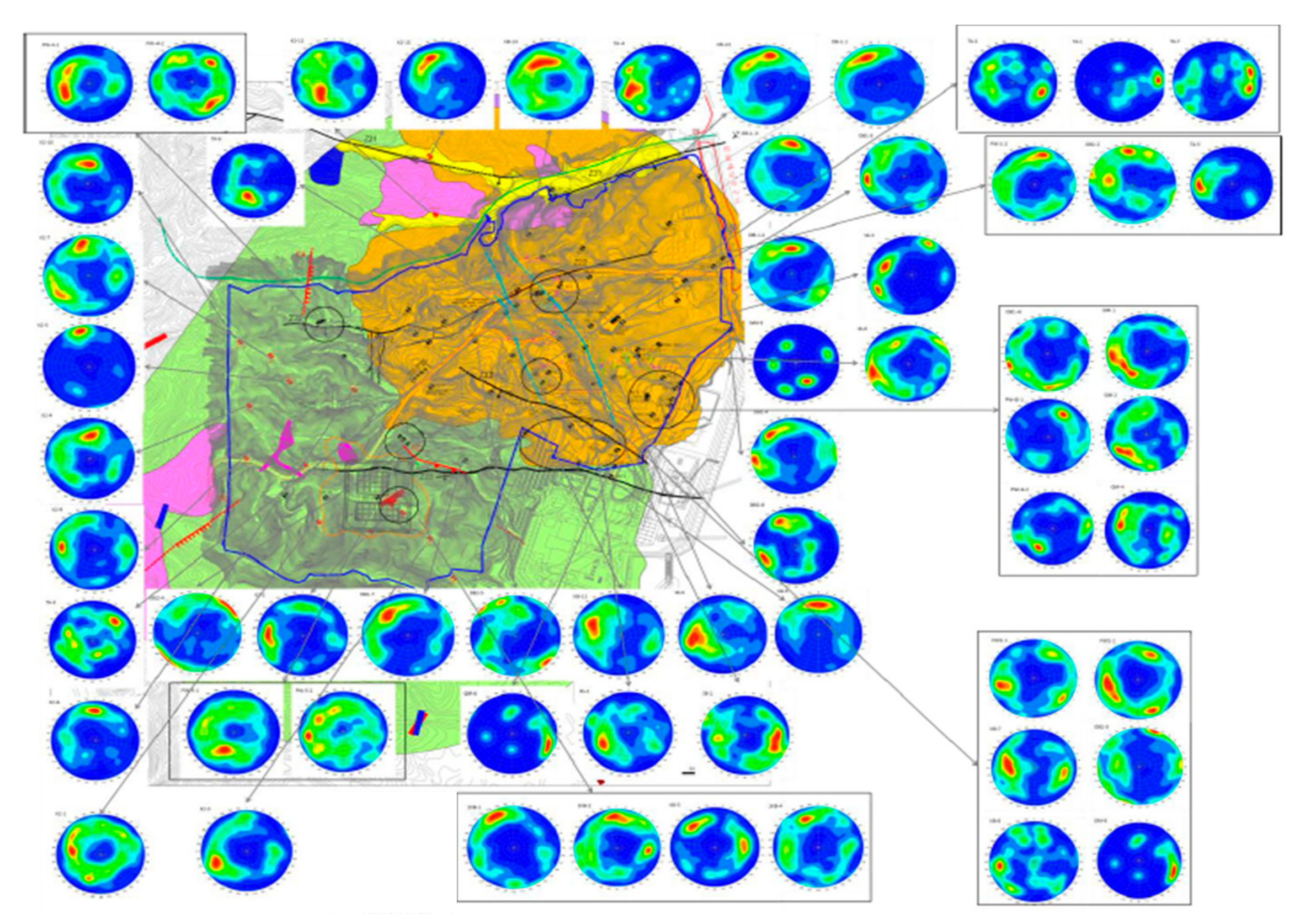
To understand the nuclide migration path at and around the Gyeongju site, groundwater flow along fractures should be revealed. In the study area, heterogeneous fracture distribution including the density and orientation of the fractures was formed through long periods of various geological activities. This study aims to generate the distribution of hydraulic parameters in the immediate and surrounding fractured bedrock at the Gyeongju site which has experienced geological activities over long periods, especially at the end of Cretaceous. For this study, the DFN approach is undertaken considering detailed analysis of heterogeneous fracture distribution, density, and orientation in the bedrock (
Figure 1). To represent the regional fracture heterogeneity, multiple linear regression was applied to find the relationship between local data (borehole fracture intensity) and regional data (faults, electrical resistivity). To take into account the connectivity of conductive fractures, fracture hydraulic parameters were estimated and calibrated using interference test results by simulating transient pressure changes throughout the connected discrete fractures. Upscaling of the DFN into the equivalent porous medium (e.g., FEFLOW) was performed.
2. Geological Setting
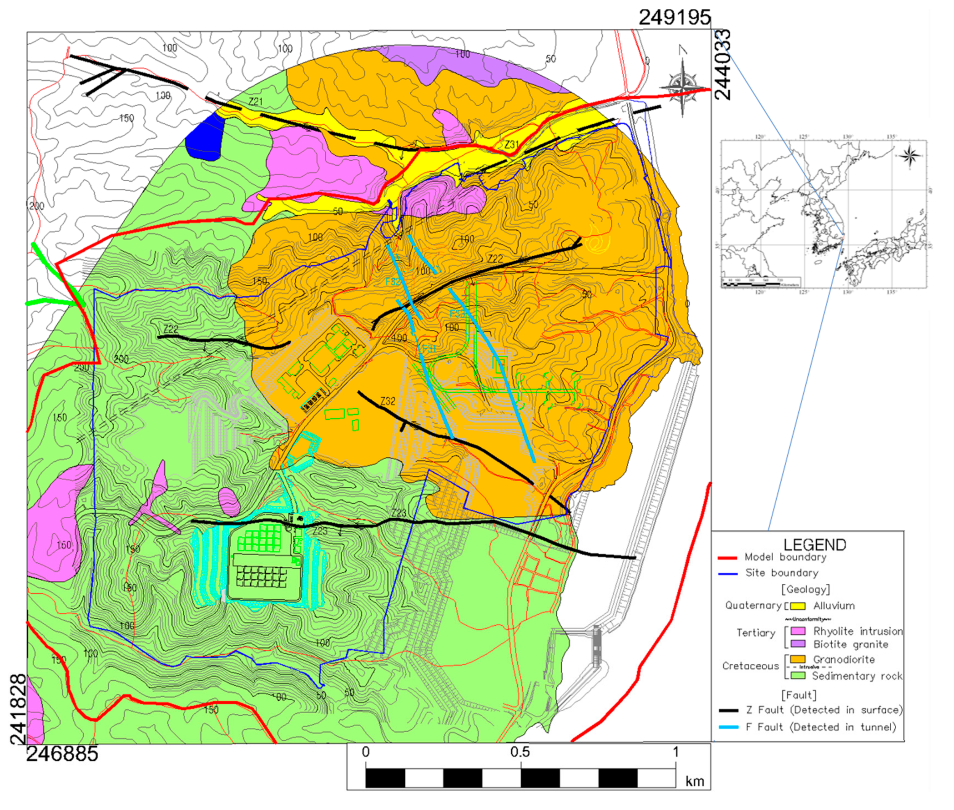
The topography of the study area shows an overall decreasing altitude from the west to the east (
Figure 2). As the valleys and ridges extend eastward, small streams flow from the highlands in the west into the East Sea. In the vicinity of the estuaries, coastal deposits and small-scale alluvial deposits form. In the study area, the runoff of the small, short stream channels only flow during the wet season, and cease during the dry season.
Geologically, the study site and surrounding area belong to the Gyeongsang supergroup, and consists of Cretaceous sedimentary rocks (shale and sandstone), Tertiary diorite, granodiorite, biotite granite, feldspar porphyry, rhyolite, and basaltic andesite and porphyritic dacitic andesite formed by tertiary volcanic activity (
Figure 2). The first stage cavern-disposal facility is located in an area of granite, while the second stage surficial disposal facility is predominately located in an area of sedimentary rock. Substantial fractures and faults occur in both the granite and sedimentary rock areas.
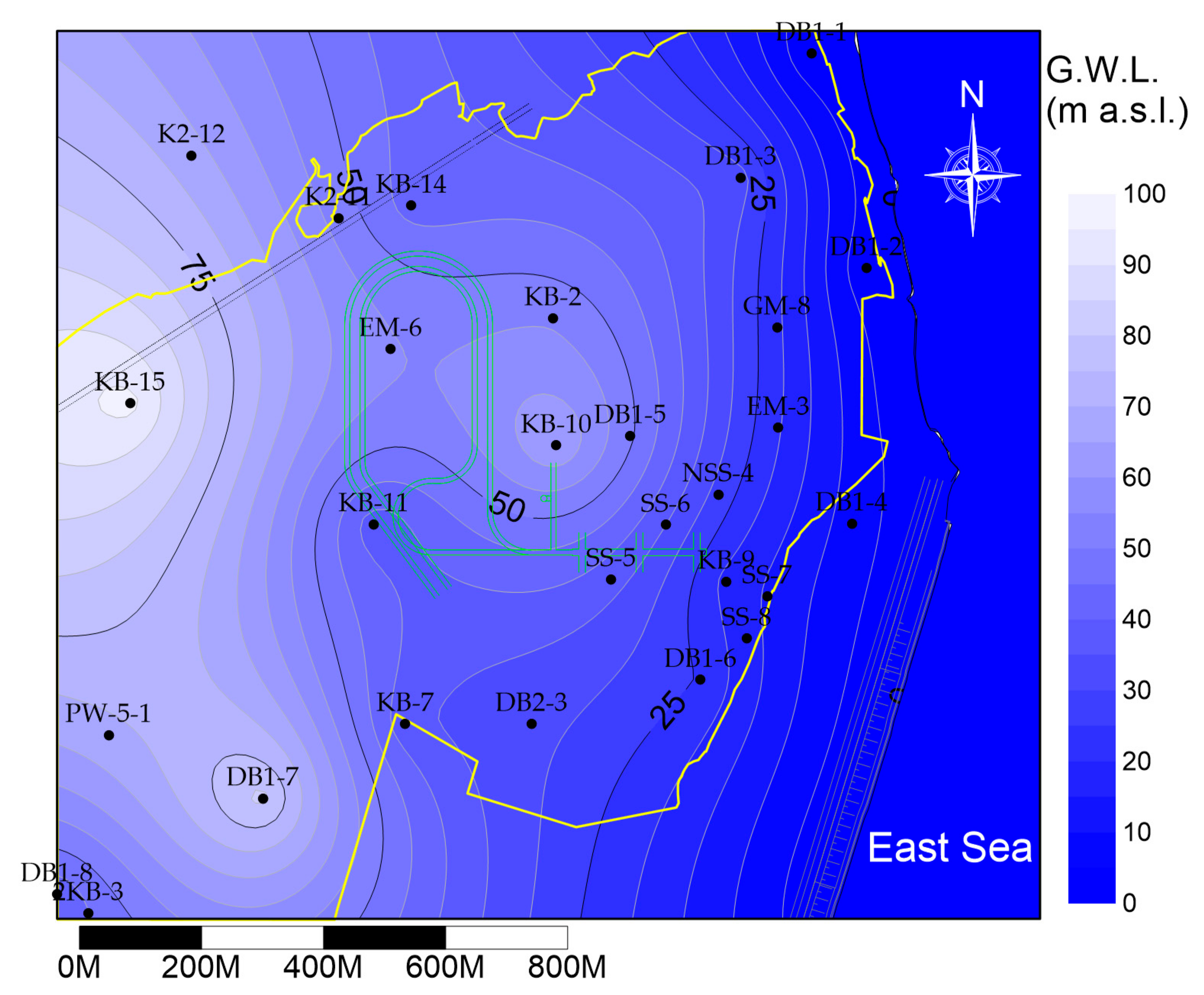
At the Gyeongju site, groundwater mainly moves through the granite and sedimentary rock factures and flows from mountainous areas in the west to the East Sea in the east (
Figure 3).
Figure 3 was plotted using groundwater heads (a.m.s.l., m) measured in April 2008, prior to construction of the radioactive waste repository. Additionally, the highlands and streams bind the groundwater systems as the eroded hills are geomorphologically bound by the rivers.
4. Results
4.1. Relationship between Fault and Fracture Intensity
Fracture intensity is defined by “Pxy” notation in this study [
20]. The two subscripts x and y refer to the dimensions of the sampling space and of the sample measure (respectively), such that that ‘3’ is volume, ‘2’ is area, ‘1’ is length, and ‘0’ is count. For example, P
10 [1/m] is the number of fracture per unit length, P
32 [m
2/m
3] is the total fracture area per unit volume, and P
33 [m
3/m
3] is the total fracture volume per unit volume. P
32 is determined as P
10 multiplied by conversion factor [
21]. P
33 is computed as P
32 multiplied by aperture size.
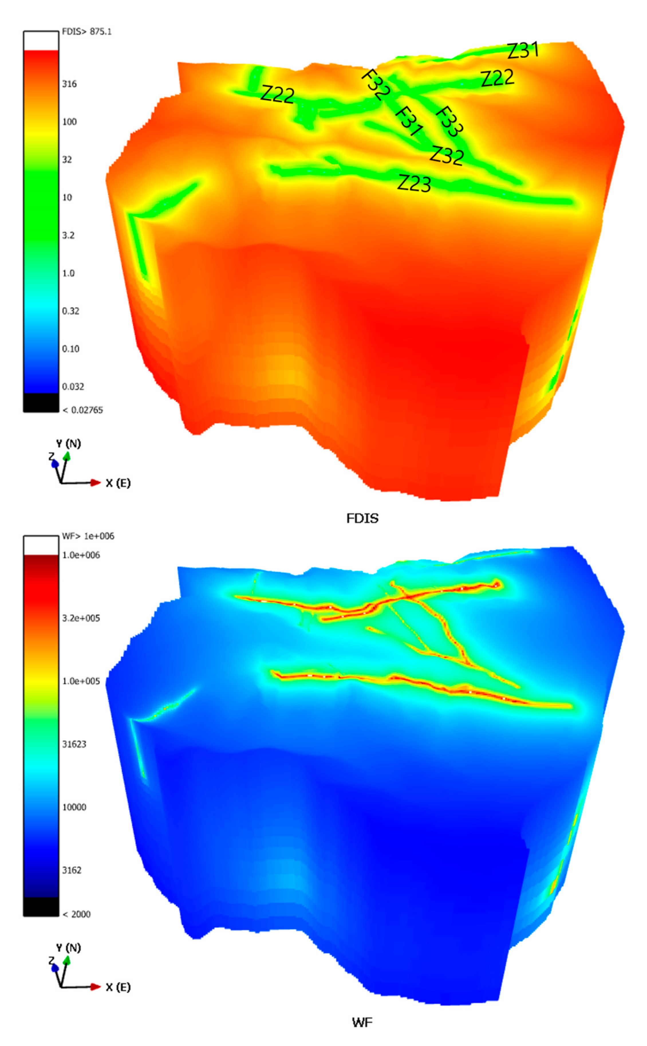
The minimum distance from fault (FDIS) and fracture density along depth (P
10) as well as the normalized inverse distance from faults weighted by nearest fault size (WF) and P
10 were examined to relate fault and fracture intensity (
Figure 7). The Pearson correlation coefficient of FDIS vs. P
10 was −0.141, with a significance level of 0.128. On the other hand, the Pearson correlation coefficient of WF vs. P
10 was 0.261, with a significance level of 0.00435. Therefore, the relation of WF vs. P
10 was more significant, indicating that the greater the fault size, the higher the fracture intensity.
4.2. Relationship between Electrical Resistivity and Fracture
The electrical resistivity survey data were correlated with the fracture density data of the boreholes located along the resistivity survey lines. When considering a 10-m survey line, the correlation analysis was performed using the maximum, minimum, and mean resistivity values within 10 m of the boreholes’ intersections, and resulted in correlation coefficients of −0.049, −0.123, and −0.056, and significance levels of 0.596, 0.550, and 0.185, respectively. The relatively low correlation coefficients of the maximum and mean values were due to a few high-resistivity values.
4.3. Multiple Linear Regression Analysis
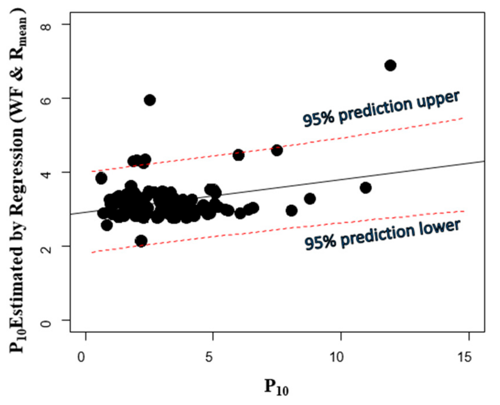
Multiple linear regression is a statistical analysis method used to predict a dependent variable (or observed data) from two or more independent variables. In order to reflect the heterogeneity of the study area, multiple linear regression analyses of P
10 were performed using two independent variables: the inverse distance from the faults weighted by nearest fault size, and the minimum electrical resistivity value. The resulting regression model for fracture intensity (P
10) was obtained as (
Figure 8):
where WF is the normalized inverse distance from the faults weighted by nearest fault size, and R
mean is the normalized mean electrical resistivity value. The significance level of the regression model, WF, and R
mean were 0.005, 0.001, and 0.117, respectively. The VIF (variance inflation factor) is 1.0992 (i.e., no collinearity problem). The effect of the WF on fractures was 1.38 times larger than the R
mean. The obtained regression model in Equation (1) shows that fracture intensity is higher with increasing WF and decreasing R
mean, which can be interpreted to mean that fracture intensity is increased at the locations closer to the large faults and having smaller mean electrical resistivity. This result corresponds well with having a higher degree of fracturing in the vicinity of faults and lower electrical resistivity in fracture zones containing groundwater.
4.4. Upscaling of Hydraulic Parameters
Hydraulic parameters of discrete fractures should be converted to equivalent hydraulic parameters on grids by upscaling. In this study, the transmissivity (T [m2/s]) and storage coefficient (S [–]) of fractures were estimated using the transient flow simulations performed by finite element modeling in FracMan®, a method called dynamic calibration. The dynamic calibration determined the hydraulic parameters of fractures having a fracture radius ranging from 14 m to 172 m by matching numerically simulated flow through the DFN model with the actual pressure transient data obtained in the field. Upscaling determined the hydraulic parameters of the fractures ranging from 1.5 m to 172 m as explained below.
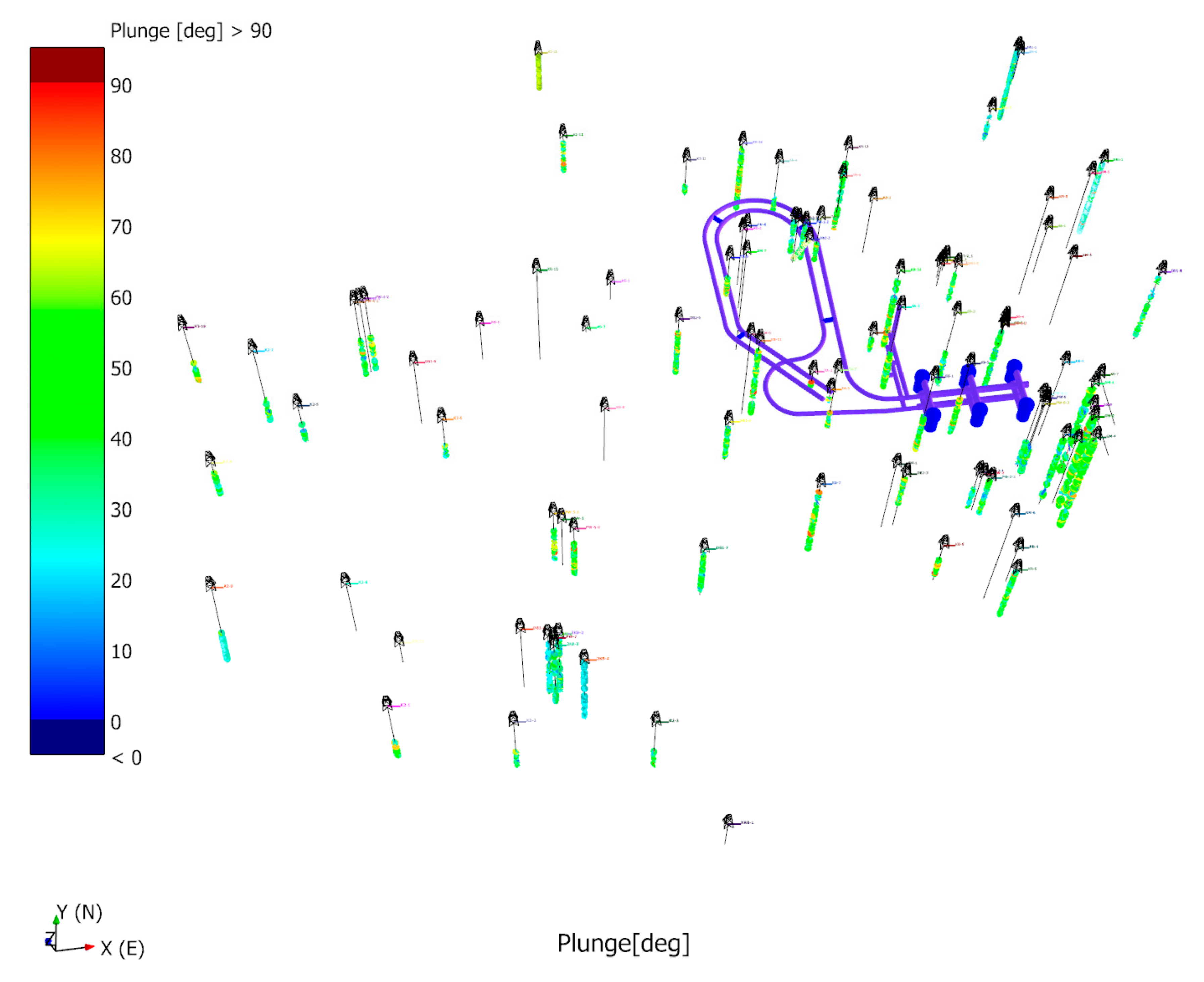
In the current DFN model, the volumetric fracture intensity of P
32 is 3.0 [m
2/m
3] obtained from 60 BHTV data, and the minimum fracture radius is 1.5 m (r ≥ 1.5 m) which was estimated based on a fracture size analysis using measured fracture traces in underground tunnel silos. Transmissivity (T) and storage coefficients (S) were first determined by the dynamic calibration of a fracture radius of 14 m or more using interference test results by matching transient pressure changes throughout the constructed DFN model. Interference tests are pumping tests that are performed when monitoring heads in observations wells. They are particularly useful for determining connectivity in fracture networks. Then, T and S calculated using a fracture radius (r) of 14 m or more (i.e., r ≥ 14 m) are calibrated by compensating excluded fractures with a fracture radius between 1.5 m and 14 m. Thus, hydraulic parameters for each fracture are obtained for all fractures in the current DFN model (r ≥ 1.5 m) (
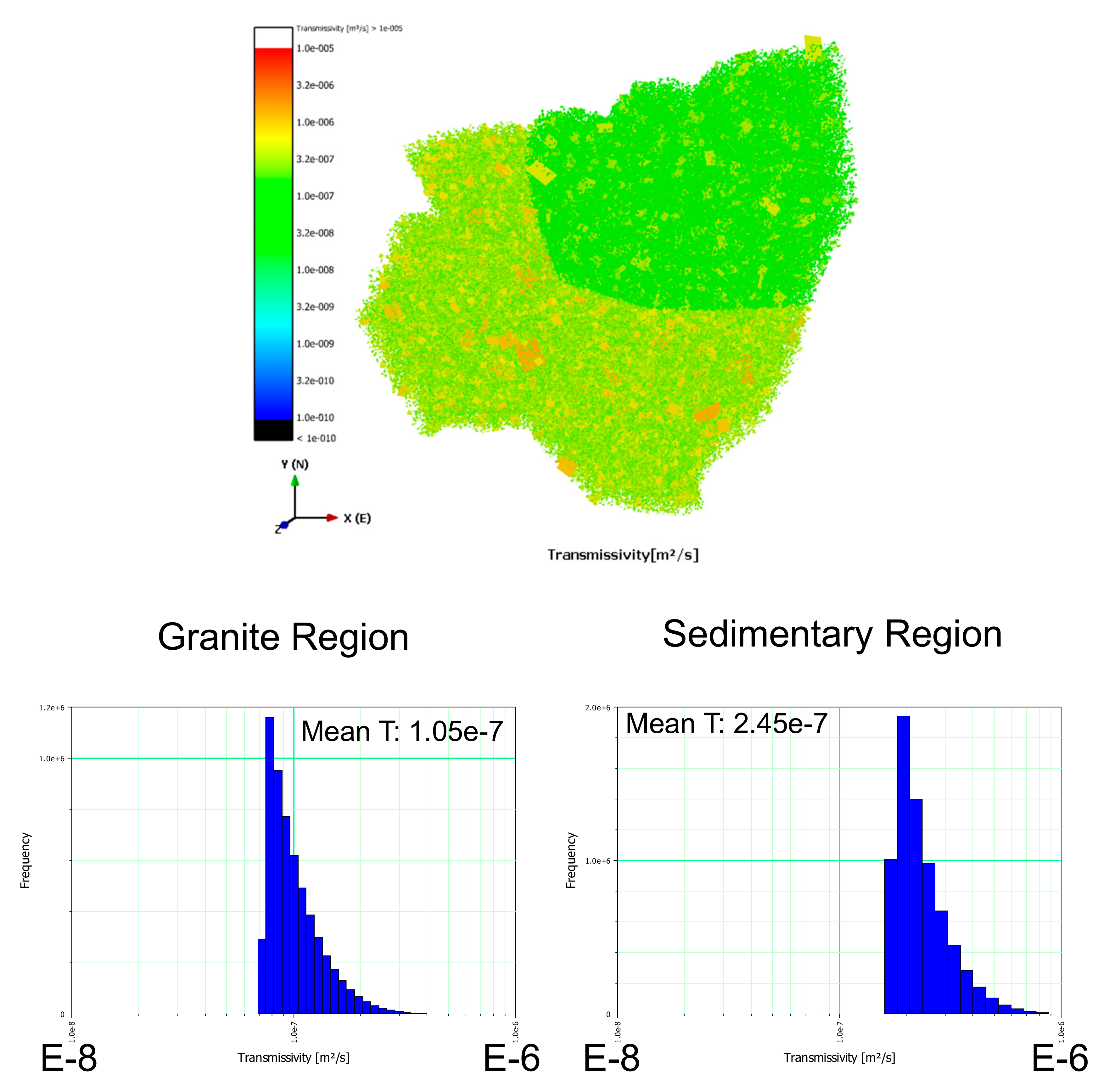
Table 2). The calibrated hydraulic parameters were applied to the DFN upscaling. The mean T values of the granite and sedimentary rock areas were 1.05 × 10
−7 [m
2/s] and 2.45 × 10
−7 [m
2/s], respectively. The distributions of fracture T values represented in the DFN are shown in
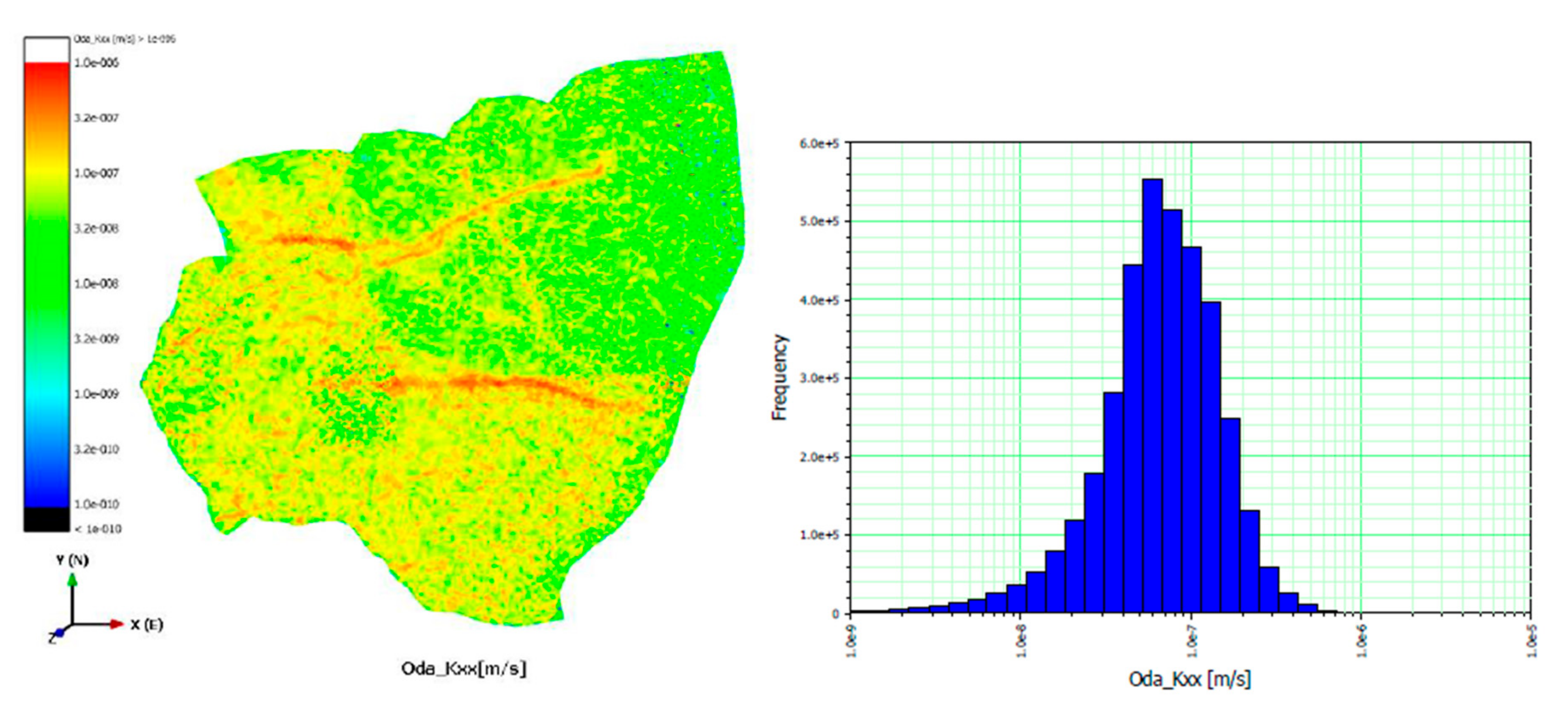
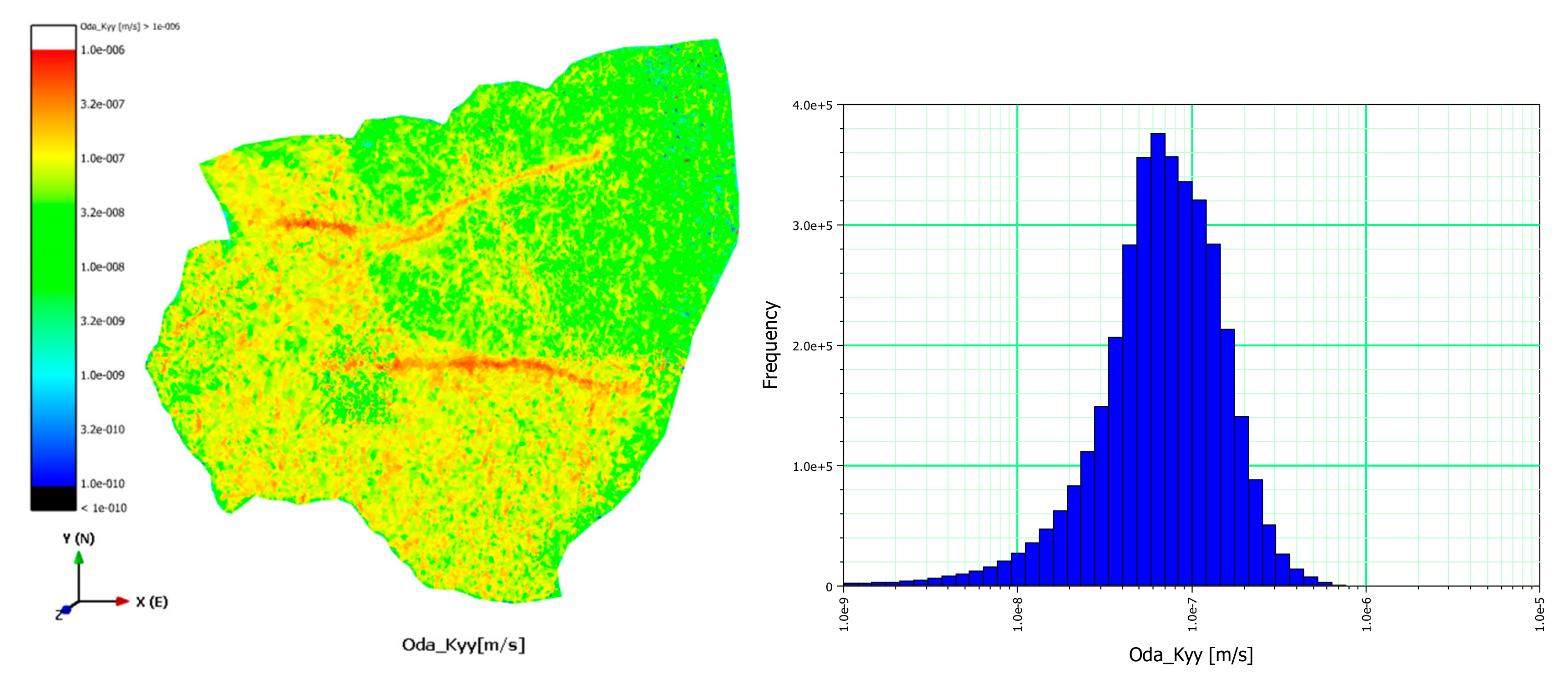
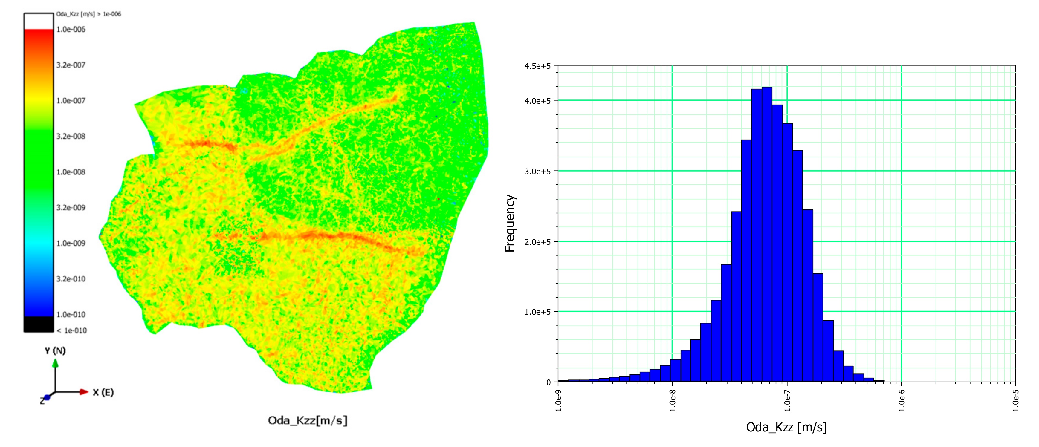
Figure 9. The hydraulic conductivity tensors (K
xx, K
yy, and K
zz) were calculated as T values divided by the aperture size depending on axes. The upscaled mean (μ) and standard deviation (σ) of K
xx, K
yy, and K
zz were obtained for the FEFLOW grid as (μ = 8.25 × 10
−8 m/s and σ = 6.97 × 10
−8 m/s), (8.42 × 10
−8 m/s, 7.04 × 10
−8 m/s), and (8.11 × 10
−8 m/s, 6.67 × 10
−8 m/s), respectively (
Table 3).
A total of 3,834,554 grid cells were generated by FEFLOW for the DFN upscaling, as shown in
Figure 10. The porosity of the fractures and the hydraulic conductivity tensor were calculated for each grid cell that was generated by the upscaling process. Spatial upscaled hydraulic conductivity tensors and bar graphs are displayed in
Figure 11,
Figure 12 and
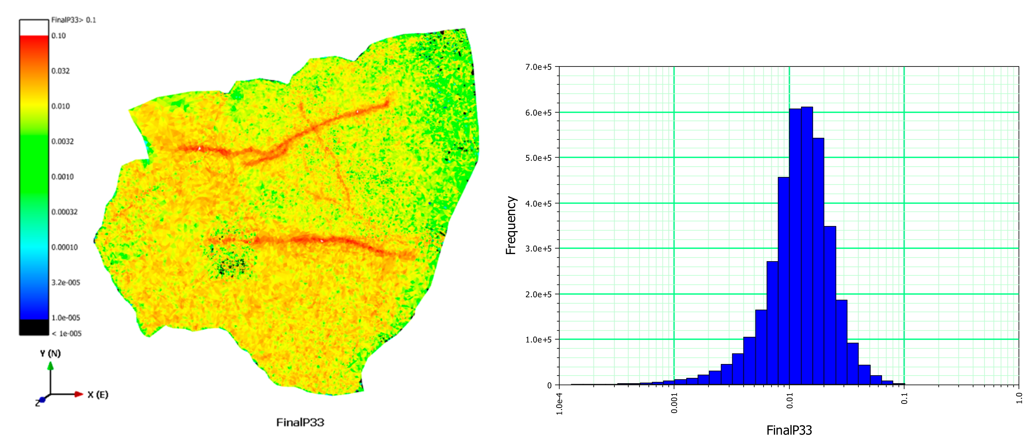
Figure 13. Fracture porosity is the total volume of the fractures divided by the volume of each grid cell. The representative fracture porosity values corrected by the upscaling had a mean value of 0.014 with a standard deviation of 0.001.
Figure 14 shows the spatial distribution of the corrected facture porosities with a bar graph. Hence, it was identified that the upscaled FEFLOW grid incorporated the heterogeneity and anisotropy of the fractured bedrock in the Gyeongju site, based on the distribution of the hydraulic conductivity tensors and porosity.
5. Conclusions
A 3-D discrete fracture network (DFN) model was constructed taking into account regional fracture heterogeneity and the connectivity of conductive fractures for the Gyeongju radioactive waste disposal site in Korea. The DFN model incorporated a total of 13 deterministic faults with lengths between 172 m and 1.4 km as well as an average volumetric background fracture intensity (P32 = 3.0 [m2/m3]) with fracture radius between 1.5–172 m. This study showed that fracture intensity was increased at the locations closer to the large faults and of lower electrical resistivity in the study area. The regional heterogeneity of fracture intensity was incorporated using a multiple regression analysis such that 1D fracture intensity was estimated as P10 = 2.365 + 3.265 × 10⁻⁵WF − 2.357 × 10⁻⁵Rmean, indicating that fracture intensity varied with respect to the normalized inverse distance from the faults weighted by nearest fault size (WF) in terms of the geological aspect, and the normalized mean electrical resistivity value (Rmean) in terms of the geophysical aspect.
The hydraulic parameters (transmissivity and storage coefficient) of discrete fractures were determined by transient flow simulation through the connected conductive fractures. Average fracture transmissivity was obtained as 1.5 × 10⁻⁷ [m2/s] for the granite area and 2.45 × 10⁻⁷ [m2/s] for the sedimentary rock area. The upscaled mean (μ) and standard deviation (σ) of hydraulic conductivity tensors for a FEFLOW grid were determined as (μ = 8.25 × 10⁻⁸ m/s and σ = 6.97 × 10⁻⁸ m/s), (8.42 × 10⁻⁸ m/s, 7.04 × 10⁻⁸ m/s), and (8.11 × 10⁻⁸ m/s, 6.67 × 10⁻⁸ m/s) for Kxx, Kyy, and Kzz, respectively.
The upscaled FEFLOW grid incorporated the heterogeneity and anisotropy of the fractured bedrock in the Gyeongju site reasonably well, based on the distribution of the hydraulic conductivity tensors and porosity. Therefore, the estimated hydraulic parameter using the current DFN model will be utilized for the groundwater flow and radionuclide transport analyses in order to assess the performance and safety of radioactive waste disposal sites in Korea.
