Article

A Hybrid Heuristic Optimization Approach for Leak Detection in Pipe Networks Using Ordinal Optimization Approach and the Symbiotic Organism Search

Institute of Environmental Engineering, National Chiao Tung University, Hsinchu 30010, Taiwan
Water 2017, 9(10), 812; https://doi.org/10.3390/w9100812
Submission received: 22 September 2017 / Revised: 19 October 2017 / Accepted: 22 October 2017 / Published: 24 October 2017

Abstract

:
A new transient-based hybrid heuristic approach is developed to optimize a transient generation process and to detect leaks in pipe networks. The approach couples the ordinal optimization approach (OOA) and the symbiotic organism search (SOS) to solve the optimization problem by means of iterations. A pipe network analysis model (PNSOS) is first used to determine steady-state head distribution and pipe flow rates. The best transient generation point and its relevant valve operation parameters are optimized by maximizing the objective function of transient energy. The transient event is created at the chosen point, and the method of characteristics (MOC) is used to analyze the transient flow. The OOA is applied to sift through the candidate pipes and the initial organisms with leak information. The SOS is employed to determine the leaks by minimizing the sum of differences between simulated and computed head at the observation points. Two synthetic leaking scenarios, a simple pipe network and a water distribution network (WDN), are chosen to test the performance of leak detection ordinal symbiotic organism search (LDOSOS). Leak information can be accurately identified by the proposed approach for both of the scenarios. The presented technique makes a remarkable contribution to the success of leak detection in the pipe networks.

1. Introduction

The issue of potable water shortages has become more and more critical in many parts of the world. Water loss is considered as a serious problem in both developed and developing countries [1], and is attracting more and more public concern. Non-revenue water or unaccounted for water is estimated at between 20 to 40% for most countries investigated [2,3]. The inverse transient analysis (IWA) method separates water losses in distribution systems into real and apparent losses. Real losses (leakage) from pipelines or pipe networks may not only cause large economic loss, but can also affect environmental hygiene [4,5]. Leaks may create serious water quality problems, resulting in equipment failure, problematic operations management, errors in pipeline design, and significant costs [4,6,7,8,9,10]. Among the various reasons for water losses, leaks in water distribution networks (WDNs) are considered to be one of the major problems to be solved.
Basically, the leak detection and location techniques can be generally divided into two main categories, steady-state based and transient based. Many steady-state based methods, such as Acoustic Emissions [11,12] and vibration monitoring [13,14,15,16], were developed for leak detection in the pressurized pipeline. These steady-state vibro-acoustic based methods have been proven to be quite effective in previous studies. The most important advantage is that the steady-state based methods can provide the high precision results without altering the operating conditions of the system. However, these methods were generally developed based on the specialized hardware, which lead to high costs [17]. On the other hand, transient-based methods (e.g., pressure wave propagation) have been widely used to detect leaks in WDN. A transient event can be generated by a simple operation, such as valve closure and opening [18]. In the transient condition, the leak location, leak orifice size, and frictional losses will affect the head changes in the pipe network when compared with those of the system in steady-state. The major advantage of transient-based methods is that information about such leaks can be efficiently and cost-effectively obtained, because transient waves travel along fluid-filled pipes at high speed [4,5,19]. A large amount of data can be collected by a simple operation in a very short period of time. However, the transient operation may cause some undesired damage or failure in the system if the operation is not properly handled.
Many previous studies have focused on the development of numerical simulations with optimization algorithms for leak detection in a WDN. Moreover, heuristic optimization approaches have also been widely discussed in the community of water supply engineers. Several earlier researchers have used heuristic algorithms with a synthetic WDN to test their ability to detect leaks. Examples are genetic algorithm (GA) [20], hybrid genetic algorithm (HGA) [21], particle swarm optimization (PSO) [22], sequential quadratic programming (SQP) [23], central force optimization (CFO) [24], and simulating annealing (SA) [25]. Vítkovský et al. [20] demonstrated the ability of the GA in lieu of the Levenberg-Marquardt (LM) method used in [26] to identify leaking nodes and pipe friction factors in the same WDN. Kapelan et al. [21] combined the GA and LM method as a hybrid inverse transient model (HGA) to exploit the advantages of combining two methods. The HGA is more stable than LM model, and it is more accurate and faster than the GA model. Jung and Karney [22] showed that both GA and PSO are capable of solving the ITA problem. It was found that PSO is more suitable than GA not only in convergence but also in accuracy. Haghighi and Ramos [24] exploited an ITA-based optimal algorithm, termed CFO, as an inverse problem solver for leak detection in a reference leaking pipe network. CFO exhibited good accuracy for identifying the friction factor and leak location. Recently, Huang et al. [25] presented an ITA-type optimization approach, called LDSA, based on the combination of the transient flow simulation and SA to detect leaks in a laboratory pipeline and a synthetic pipe network. The SA was used to solve the inverse problem with a least-squares criterion objective function.
On the other hand, some studies applied their leak detection techniques to a laboratory pipe system or real WDNs. Ferrante et al. [27] coupled the wavelet analysis with a Lagrangian model to identify the leaks in a laboratory branched pipe system in the Water Engineering Laboratory at the University of Perugia. Their approach memorized the amplitude of each wave and the moment at which it passed the leak, and then identified the leak. Nazif et al. [28] introduced a heuristic method combined the artificial neural network (ANN) model and GA to find the optimal hourly water level variation in a water distribution storage tank for different seasons. Ferrante et al. [29] investigated the relationship between leak geometry and detectability within steady-state and transient based techniques. They used the experimental tests to demonstrate the effect of higher system pressure for leak detectability in steady-state and transient conditions. Casillas et al. [30] introduced a sensor placement approach based on either GA or PSO to detect leaks in WDNs in Hanoi and in Limassol. The results showed that PSO obtains results faster than GA, and it is very effective for smaller WDN or with fewer sensors. However, the GA provided better placement solutions with higher efficiency for larger networks or more sensors. Meniconi et al. [31] used a Lagrangian model simulating pressure wave propagation to evaluate the pipe pressure wave speed and to locate the possible anomalies by coupling GA and wavelet analysis, respectively. Their approach was further executed in a part of the WDN of Milan for providing the diagnosis of the pipe system. Lee et al. [32] integrated the advantage of the methods of cumulative sum and wavelet transform to effectively detect the sudden pressure changes of WDN. The pressure data obtained from the real burst accident were used to verify their burst detection and location algorithm. Moreover, many other studies were devoted to the development of optimization approaches for leak detection in real cases [19,33,34].
This paper focuses on solving the leak detection problem, as well as the number of leaks, their location, the value of CdA (discharge coefficient multiplies area opening of the orifice) in the pipe network, with optimum transient perturbations. A hybrid heuristic approach, called leak detection ordinal symbiotic organism search (LDOSOS), is developed based on the ordinal optimization algorithm (OOA) and symbiotic organism search (SOS) for automatically determining leak information in a leaking pipe network. In order to examine the performance of the proposed approach, two synthetic leaking scenarios with different pipe network configurations are considered. The ability of convergence compared with different optimization algorithms pertaining to the detection results is addressed in first scenario. Furthermore, the use of the optimum transient generation is demonstrated in the second scenario.

2. Methodology

This section deals with the mathematical background of forward flow simulation models, and includes steady-state and transient flow simulations in the pipeline network. The procedure of transient generation point selection is introduced in this section. Brief descriptions of OOA and SOS, and the combination of a forward flow model with OOA and SOS for the leak detection are also described.

2.1. Flow Simulation Model

Yeh and Lin [35] developed a numerical approach, termed PNSA, for estimating the steady-state nodal head and flow rate for any given pipe network. This approach uses the SOS in lieu of the SA in PNSA to solve an optimal water head distribution and the nodal flow rates in a network. The flowchart of PNSOS is shown in Figure 1.
The Hazen-Williams equation is used to express the relationship between the flow rate and head loss for each pipe [36,37]. The loss coefficient (Kij) in the Hazen-Williams equation for a pipe is defined as [38]:
K i j = 10.66667 L i j C i j 1.851852 D i j 4.870370
where ij is the variable defined from node i to node j, Lij is the length (m) of the pipe, Cij is the Hazen-Williams friction coefficient depending on the pipe material [36], and Dij is the pipe diameter (m). Based on Equation (1), the flow rate Qij in each pipe can be expressed as
Q i j = ( Δ H i j K i j ) 0.54
where ΔHij is the frictional head loss in a pipe. The equation of mass conservation at node i can be written as
M C i = j = 1 n n Q i j + Q I i
where nn is the number of total neighbor nodes to node i and QIi is the demand or the source at node i. The flow rate is positive for flowing out of node i and negative for flowing into node i, while QIi is positive for inflow and negative for outflow. Therefore, the objective function used in the PNSOS is defined as
M i n i m i z e i n d ( M C i ) 2
where nd is the total number of nodes needed to estimate the nodal heads and flows in a network system.

2.2. Hydraulic Transient Model

Since the steady-state water head and flow rate for each node in the network has been estimated, the hydraulic transient can then be evaluated from the following momentum equation and continuity equation [25,38]:
m o m e n t u m : g A H x + Q t + f 2 D A Q | Q | = 0
c o n t i n u i t y : H t + a 2 g A Q x = 0
where g is gravity acceleration, A is pipe cross-sectional area, H is hydraulic head, x is distance along the pipe, Q is volume rate of flow, t is time, D is diameter of pipe, a is the wave speed, and f is the friction factor, which can be described by steady, quasi-steady, or unsteady state conditions. Many approaches have been presented for unsteady friction modeling, such as weighting function-based model [39,40] and the instantaneous acceleration-based model [41,42]. Since this work is not experimentally oriented, the friction factor is considered to be steady. Moreover, the elastic behavior is assumed for pipe material and then the effects of viscoelasticity are not considered. The method of characteristics (MOC) is a common technique for solving hydraulic transient equations [43]. Equations (5) and (6) are then transferred to the following two sets of ordinary differential equations along the characteristic lines (dx/dt = ±a):
C + : { d H d t + a g A d Q d t + f a 2 g D A 2 Q | Q | = 0 d x d t = + a
C : { d H d t + a g A d Q d t + f a 2 g D A 2 Q | Q | = 0 d x d t = a
where dx is the distance differential and dt is the time differential. With appropriate initial and boundary conditions, the finite difference method is applied to approximate Equations (7) and (8), and simultaneously calculate the transient head and flow rate in the grid points in the network. Boundary conditions often consist of known pressures and flow rates at the pipe network, which are generally reservoirs, connections, valves, pumps, and leakages. The leaks in the networks may be represented by orifices and expressed as [44]:
Q L = C d A 2 g Δ H
where QL is the volumetric flow rate of the leak, CdA is the discharge coefficient times the effective area of orifice, and ΔH is the head loss caused by the orifice.

2.3. Excitation Procedure for Transient Generation

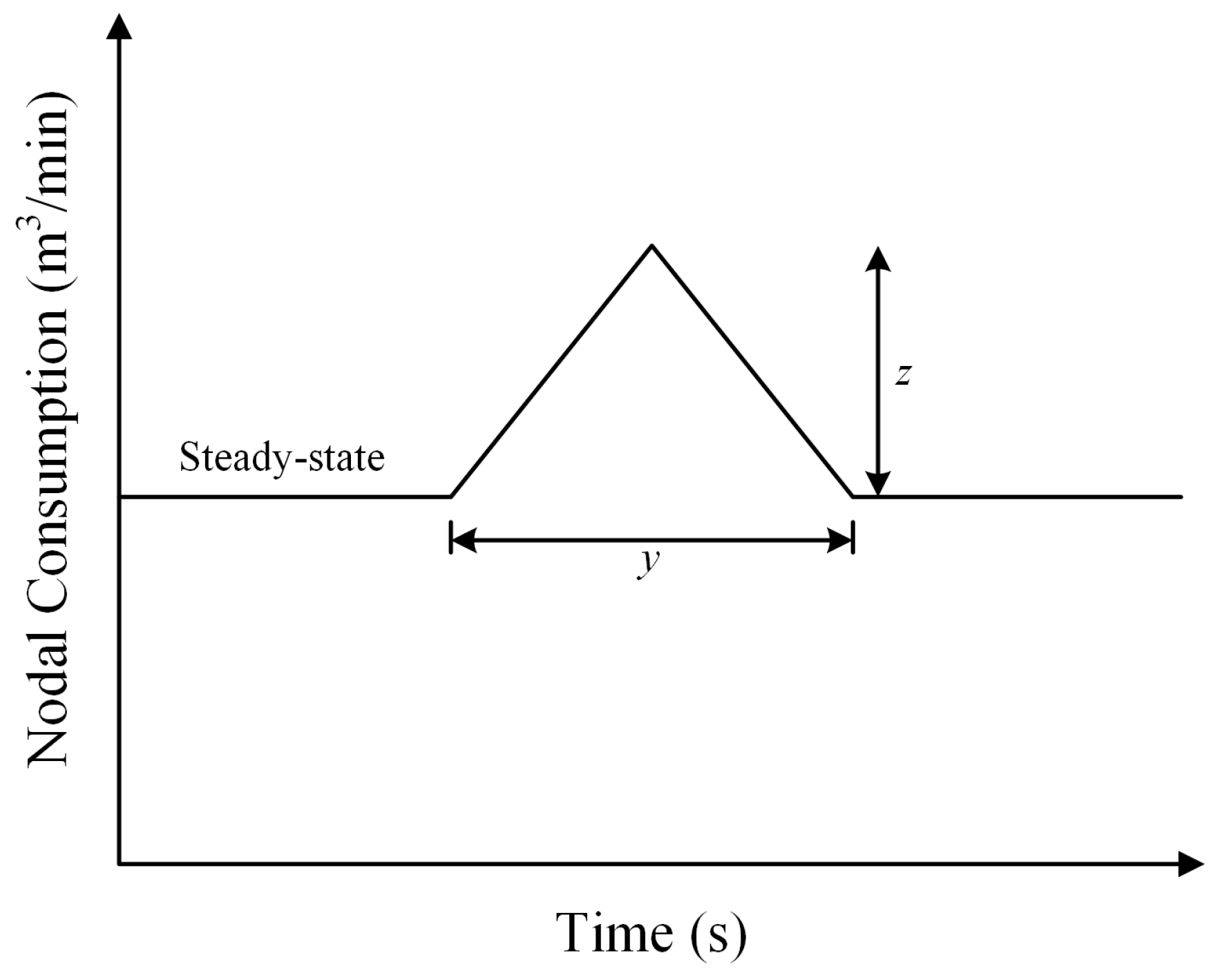
For leak detection in pipe networks using ITA, the problem of the generation of pressure waves is a very important issue of transient test-based techniques. The worst transient fluctuations are usually required because the severity of transient fluctuations is related to the efficacy of applying ITA. The possibility of the use on hydraulic transient for leak detection have been experimentally validated in laboratory conditions by using the Portable Pressure Wave Maker (PPWM) device [45,46], and further applied in field tests [47,48,49]. Generally, valve operation is a common way to create a change in the outflow discharge for obtaining transient fluctuations [18]. Vítkovský et al. [19] suggested that a valve, as a transient generator, should be closed very quickly with a small discharge magnitude. Thus, the optimal transient generation location and operation parameters for generating the optimal transient perturbations should be determined while using ITA. Valve operation is also termed excitation, as shown in Figure 2. Note that Figure 2 are modified from [7]. The two major valve operation parameters are the duration of change y and the amount of change z for controlling the intensity of transient fluctuations. On the other hand, another parameter is the side curves of the excitation, which are usually non-linear and depend on valve type and its operation. The side curve is considered to be linear for convenience in numerical verification. Haghighi and Shamloo [50] noted that the intensity index, E, is the accumulative energy of transient heads evaluated from function of parameters y and z for each candidate point (i.e., node in pipe network). To obtain the optimum transient perturbations in the pipe network, the intensity index E should be maximized while using each candidate node as a transient generation point with corresponding operation parameters. The objective function for determining the optimal parameters y and z for each candidate node with maximum accumulative energy is described as [50]:
M a x i m i z e : E ( y , z ) = t s = 1 n t i = 1 n d | H i t s H i 0 H r | × t s = 1 n t i = 1 n d P e i t s
P e i t s = { H i t s H m i n H m i n > H i t s 1 H m i n H i t s H max H max H i t s H max < H
where E is the overall energy of heads, y is the duration of outflow change, z is the consumption of the change, Hi0 is the initial steady head, Hits is the piezometric head at node i at time step ts, nt is number of transient modelling time steps, Hr is the reservoir head, Peits is the penalty factor to impose pressure constraints, Hmax and Hmin are, respectively, the maximum and the minimum permissible heads in system.

2.4. Ordinal Optimization Approach

The key idea behind an OOA is to rank the values of the objective function in ascending order. In reality, an OOA is much easier than the process of searching for a global optimal solution [51]. Two major procedures are used in an OOA: ordinal comparison and goal softening procedures. The first procedure looks for the relative relationship between each solution in order to find better solutions; the second is to determine a reliable and satisfactory solutions instead of directly evaluating the optimal solution in a complex optimization model. Thus, the optimum solution could be obtained from a feasible solution space. The searching process in the procedure would be reduced. To obtain the top optimum proportion solutions, Lau and Ho [52] noted that the top 5% of solutions can be treated as a reliable criterion with a very high probability (≥0.95) of obtaining satisfactory solutions.

2.5. Symbiotic Organism Search (SOS)

Cheng and Prayogo [53] developed a new meta-heuristic algorithm, termed the symbiotic organism search (SOS) algorithm, which was inspired by actual biological interactions. The biological interaction between two organisms or species in a symbiotic system can be generally categorized into three types: mutualism, commensalism, and parasitism. Mutualism denotes that the relationship is beneficial each organism. Commensalism is the relationship in which one organism benefits from the other without affecting it, while parasitism represents a non-mutual relationship in which one species benefits at the expense of the other. The characteristics of SOS are similar to other population-based meta-heuristic algorithms, such as GA and PSO. SOS shares the same following four features: (1) the control parameters, such as the initial population size and the maximum number of iterations should be appropriately settled; (2) the population of organisms which contains candidate solutions are used to determine the global optimal solution in the search space during the searching process; (3) the candidate solutions are used to guide the searching process; and (4) a selection mechanism to retain better good solutions and to abandon poor solutions. Furthermore, the SOS algorithm is a parameter-free technique, and only the control parameters, such as initial population size and maximum number of iteration are required. Algorithm-specific parameters for other competing algorithms might increase computational time and produce local optimal solutions. Hence, SOS has been successfully applied to various types of problem such as the construction management [54], work shift [55], and optimal reservoir operation [56].
Figure 3 shows the flowchart of an SOS algorithm. SOS starts with an initial population named the ecosystem. A group of organisms is randomly generated in the feasible solution domain and then added into the initial ecosystem. Each organism is considered as a candidate solution (CAS) for the corresponding problem with a certain objective function value (OFV). The search procedure begins when the initial ecosystem is set up. In the searching procedure, each organism will get to benefit or be harmed from continuously interacting with another organism in three different types/forms of symbiosis explained above.

2.5.1. Mutualism State

In mutualism, organism Xi and Xj are randomly selected from an ecosystem for interaction. Both organisms interact to mutual benefit in order to increase chances of survival in the ecosystem. Hence, the new candidate solutions for Xi and Xj are modified based on the mutualistic mechanism between Xi and Xj, and is illustrated as:
X i n e w = X i + R D M × ( X b e s t M V × B F 1 )
X j n e w = X j + R D M × ( X b e s t M V × B F 2 )
where RDM is a vector of random numbers range from 0 to 1, Xbest is the current best organism with the best OFV in the ecosystem, MV is the mutual vector defined as MV = (Xi + Xj)/2, and BF1, and BF2 are the benefit factors randomly as either 1 or 2.

2.5.2. Commensalism State

Similar to mutualism, the organism Xj is randomly chosen from the ecosystem to interact with another random organism Xi. Xi gains benefit from Xj, but Xj is not affected by this relationship. The new Xi can be modified as:
X i n e w = X i + R D C × ( X b e s t X j )
where RDC is the vector of random numbers range from −1 to 1.

2.5.3. Parasitism State

In parasitism, a parasitical organism XP is generated by cloning and mutating it from Xi in random dimensions, using a random number with a range between given lower and upper bounds. A parasite XP tries to replace the random host organism Xj. Both XP and Xj are then evaluated for their fitness (OFVs). If the parasite has a better OFV, the host organism will be immediately replaced by the parasite. If the OFV of Xj is better, then Xj will survive and kill the parasite XP.

2.6. Development of LDOSOS

Abhulimen et al. [57] recorded that pressure measurements are more sensitive than volume measurements for leak detection. Hence the objective function of ITA is defined in terms of pressure head as:
M i n i m i z e j = 1 m i = 1 n ( H o i j H s i j ) 2
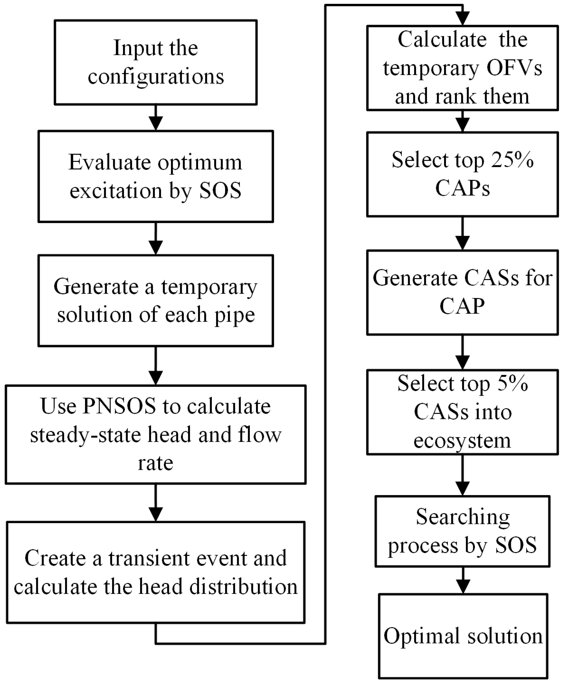
where m is the total number of observation points in the network, n is the number of observations made at an observation point, and Hoij and Hsij are ith observed, and simulated heads at the observation point j, respectively. The LDOSOS can automatically determine the leak information based on the minimization of Equation (15). The procedures of LDOSOS are summarized in Figure 4. The LDOSOS can be used to determine the optimal leak location, leak size, and the number of leaking pipes simultaneously. The procedure for detecting the leaks using LDOSOS is given below:
  • Import the network configurations.
  • Use SOS to determine the optimal transient generating point with its corresponding operating parameters (i.e., y: duration of outflow change, z: amount of nodal consumption variation) by maximizing Equation (10). The optimum solution is obtained when the OFV of Equation (10) does not change within four iterations.
  • For the pipe sifting procedure in OOA, successively generate a temporary leak which is located at the middle of each pipe; the location and CdA of the orifices are treated as temporary solutions.
  • Since the temporary leak solutions are available, PNSOS is then used to calculate the steady-state nodal heads and flow rates in the network.
  • Generate a hydraulic transient event at the optimal generation point and apply Equations (7) and (8) to simulate the head distribution in the network.
  • Apply Equation (15) to calculate the temporary OFV for the temporary solution of each pipe.
  • Arrange all of the pipes according to the values of temporary OFVs. A quarter of pipes with smaller OFVs are chosen as candidate pipes (CAPs). Only the CAPs will be used in the further steps.
  • Randomly generate 200 CASs with the information of a leaking pipe, leak location and CdAs of the orifices, and calculate their OFVs. The top 5% CASs would then be selected for the next step.
  • Consider the best 5% CASs as the initial organisms for the ecosystem.
  • Execute a searching process using SOS. In general, mutualism and commensalism states are used to guide the organisms toward the current best organism, and the parasitism state is applied to avoid the organism becoming stuck in a local optimal solution.
  • Check whether the optimization process satisfies the stopping criterion or not. If so, the LDOSOS is then terminated; otherwise, the searching process goes on and back to the tenth step.
Note that the first stopping criterion is defined as the absolute value of the difference between the two successive optimal OFVs of Xbest which are all less than 10−4 within four iterations. The second criterion is that the iteration reaches 10,000 times.

3. Results and Discussion

3.1. Pipe Networks Setting

To test the applicability of LDOSOS in leak detection, two scenarios with different synthetic pipe network systems adopted from the literature are used. These two pipe networks are designed based on the concept of district metering areas (DMA), in which inflow and outflow are monitored. User demands and leaks are assumed as constants and can be separated through continuous observation of mass conservation of flow measurements.
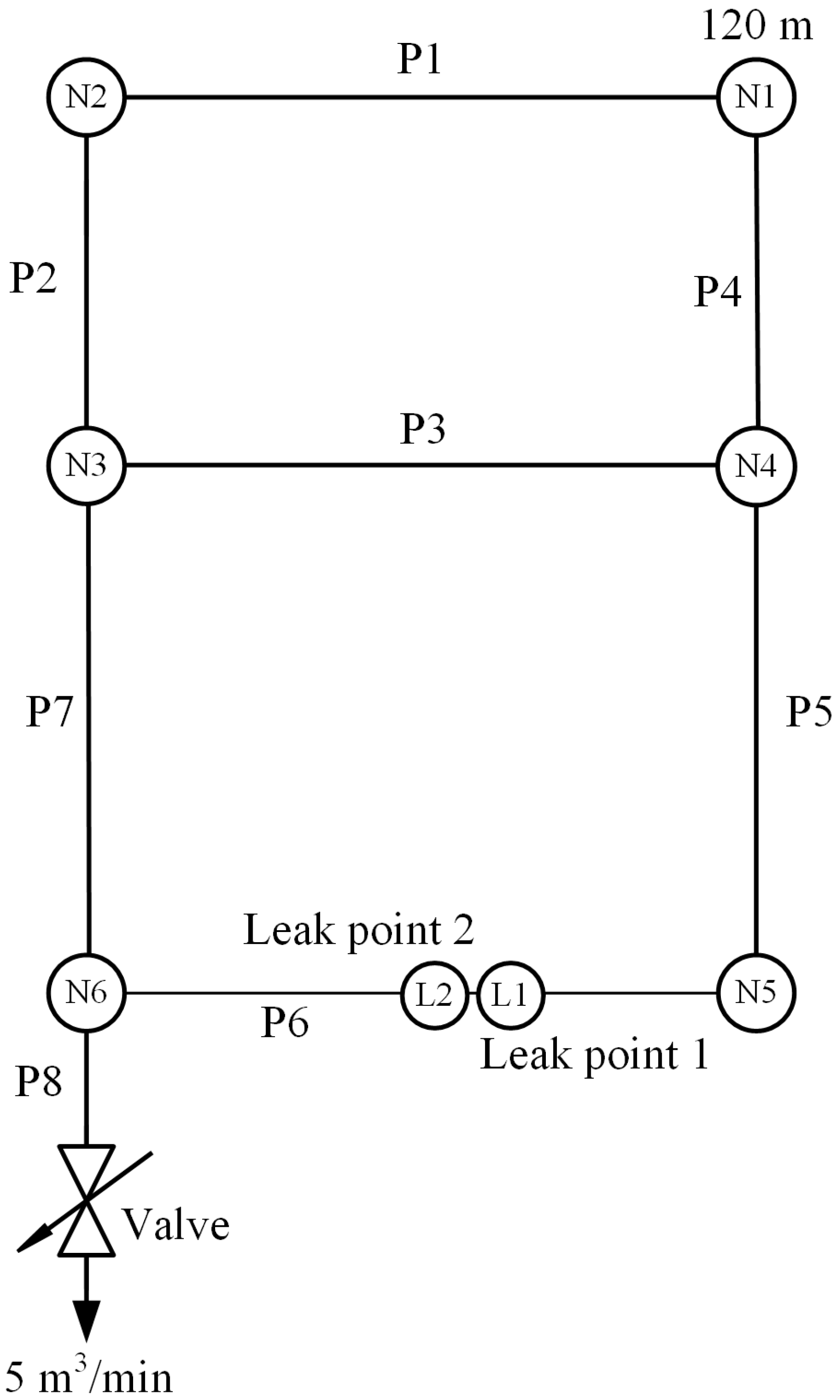
The first scenario (S1) is the one presented in [25], with a layout referred to as pipe network A, as shown in Figure 5. The configuration of this network consists of eight pipes, six nodes, two potential leaks, and one downstream valve, and the characters “N”, “P”, and “L” represent the node, pipe, and leak, respectively. The pipe diameter varies from 250 to 500 mm, while the pipe length varies from 1000 to 1250 m. Nodal consumptions are considered as 0 for all nodes. N1 is considered as a reservoir with 120 m constant-head, and downstream of P8 is a valve with a discharge flow rate of 5 cubic m per min (m3/min). Two potential leaks, denoted as L1 and L2, are both in P6 and are at 300 and 310 m from N5, respectively, with the same CdA = 0.00025 m2 and same QL = 0.5 m3/min. The downstream valve is the only outflow of pipe network A. Hence, the optimum operation point is located at the valve. In order to compare the proposed approach with the work of [25], the operation parameters y and z are fixed to 1 s and −5 m3/min, respectively, for the simulation of a sudden closure of the valve. The characteristics of the nodes and pipes of the pipe network A are listed in Table 1.
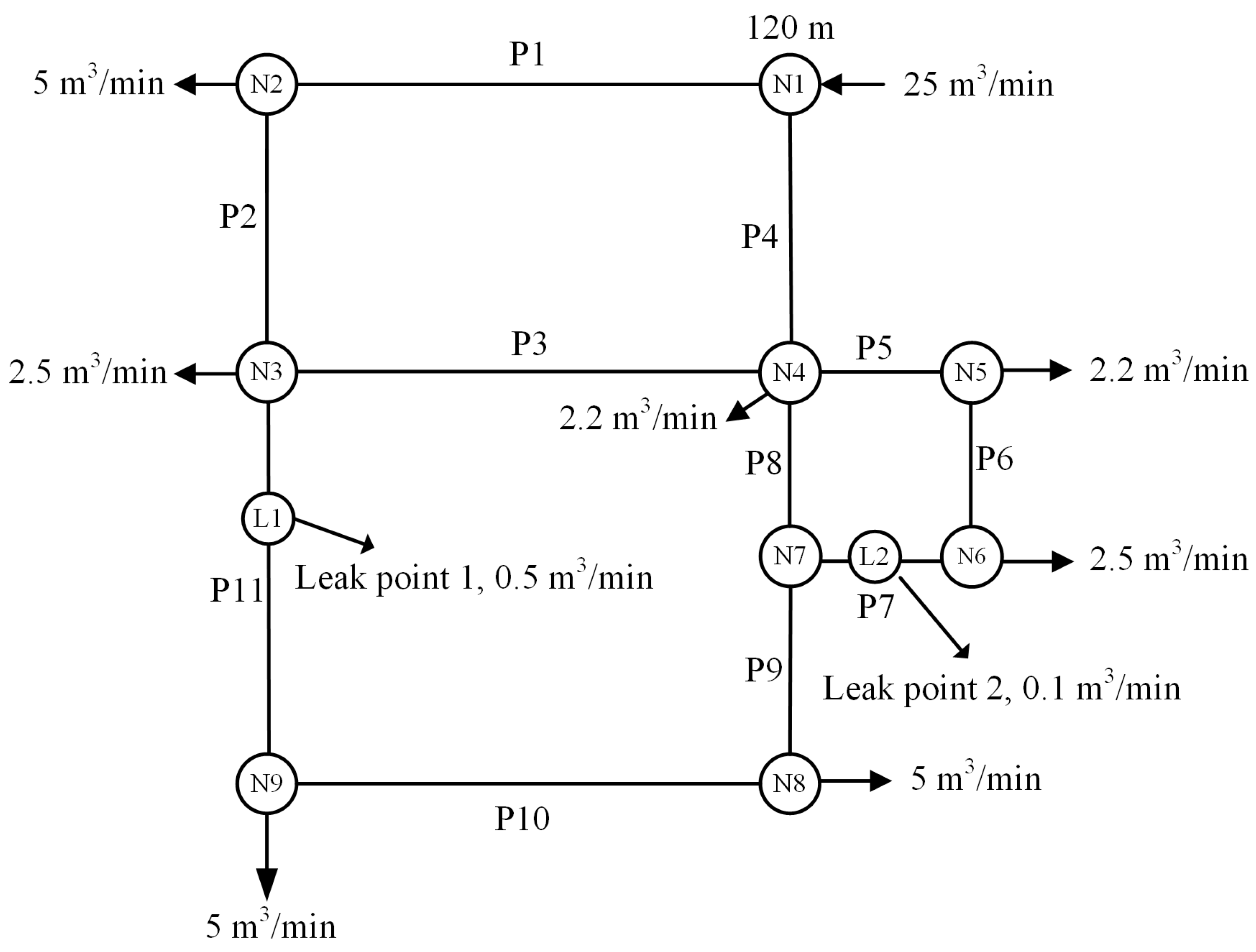
In order to solve the leak detection problems in a real WDN, scenario 2 (S2), with a synthetic pipe network B presented in [35] is considered in this study. The pipe properties are listed in Table 2. Figure 6 shows the configuration of the network which consists of 11 pipes, nine nodes, seven continually outflow points, and two potential leaks. The pipe length ranges from 400 m to 1250 m, and the diameter ranges 200 to 405 mm. The N1 is the water supply node with a constant inflow rate of 25 m3/min and constant head of 120 m. Seven outflow nodes N2, N3, N4, N5, N6, N8, and N9 continuously discharge 5, 2.5, 2.2, 2.2, 2.5, 5 and 5 m3/min, respectively. The leak L1 is in P11 and 300 m away from N3, while the leak L2 is at the middle of P7 and 250 m away from N6. The CdA and QL of L1 are 0.00025 m2 and 0.5 m3/min and CdA and QL of L2 are 0.0001 m2 and 0.1 m3/min. In pipe network B, N2, N8, and N9 are available as candidate transient generation points with larger discharges. The optimal operation point (i.e., N2, N8 and N9) and the optimal parameters, y and z, must be determined.
In both of the scenarios, all of the pipes are old cast-iron pipes and the Hazen-Williams friction coefficient is chosen as 100 [18]. The wave speed a in pipe is thus assumed to be 1000 m/s [18]. The total simulation time is 30 s. The time interval (dt) is chosen as 0.005 s for Section 3.2 and Section 3.3. On the other hand, dt is chosen as 0.005 and 0.05 s for various cases for Section 3.4. In the following sections, the application of LDOSOS to the leak detection in the simple pipe network and WDN is assessed. Moreover, the error analysis is also addressed. The simulations for the leak detection are performed on a personal computer with Intel 3.3 G E3-1230v2 CPU and 32 GB RAM.

3.2. Applicability of LDOSOS to Leak Detection

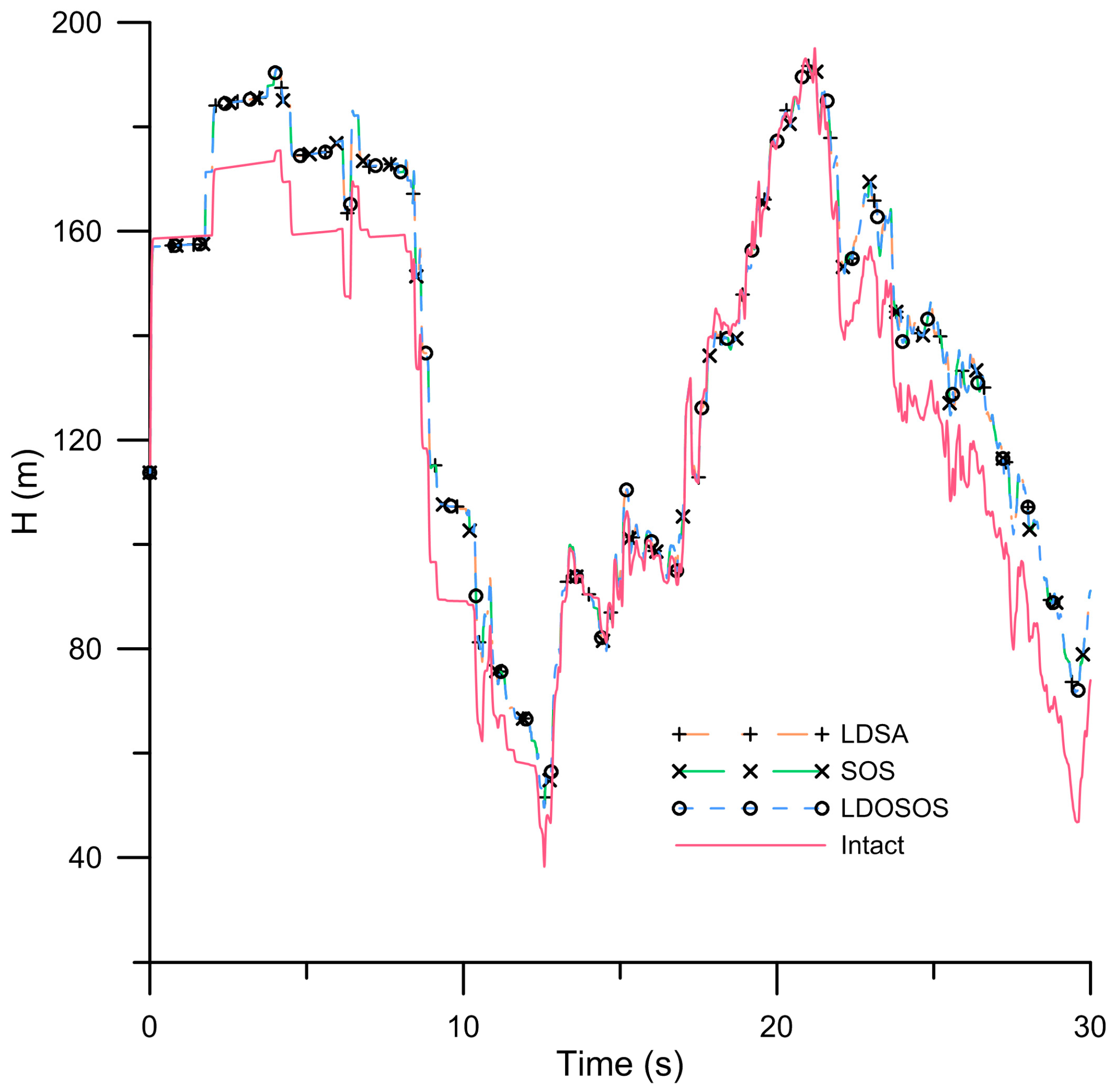
In this section, the proposed method is used to demonstrate the convergence and efficiency of leak detection in S1. The results are then compared with leak detection symbiotic organism search (LDSOS) and LDSA approaches. LDSOS is a simplified optimization approach similar to LDOSOS, but without the elimination procedure OOA. All of the pipes are treated as candidate pipes in LDSOS. Furthermore, 10 initial solutions are randomly generated from a feasible solution domain as the initial organisms for the ecosystem of LDSOS. On the other hand, LDSA is a heuristic technique based on SA for solving leak detection problems in pipe network A. In the leak detection process, LDSA randomly generated a trial solution in the network then adopted the least squares method with the minimal OFV to find the possible leak information, including the location and the value of CdA. However, the searching space in SA may be enormous and required a large computing time to find the optimal solution. By contrast, OOA is adopted in the LDOSOS to sift through the searching space. Based on the search procedure, P6 and P7 in pipe network A are first sifted and ranked as the CAPs; the top 5% CASs from CAPs with different leak information are sifted by calculating all CASs’ OFV (Equation (15)). More specifically, the top 10 best CASs ( 200 × 0.05 = 10 ) are sifted as the initial organisms for LDOSOS.
Figure 7 shows the predicted heads versus time at the valve, based on the intact network and the network with two leaks. The predicted head distributions by LDSA, LDSOS, and LDOSOS display very similar transient patterns; however, their efficiencies are quite different in obtaining optimal results. Table 3 gives the results of leak detection for S1 from LDSA, LDSOS, and LDOSOS. The results show that LDOSOS is capable to detect leaks that are close to each other. The LSDA takes 372 min and 9815 iterations, while LDSOS required 120 min and 3481 iterations to obtain the results. The efficiency of LDSOS is better than LDSA. Moreover, LDOSOS takes 50 min and 1469 iterations to complete the detection process and to obtain the optimal locations and CdAs. The convergence and efficiency of LDOSOS is greatly enhanced as a result of the sifting procedure OOA. The computing efficiency of LDOSOS is approximate 86 and 58% better than that of LDSA and LDSOS. The LDOSOS obtained the optimum solution after about 1500 iterations which is significantly less than the other two approaches. Obviously, the performance of LDOSOS is much more efficient than the other two algorithms.

3.3. Leak Determination in WDN with Optimal Transient Operation

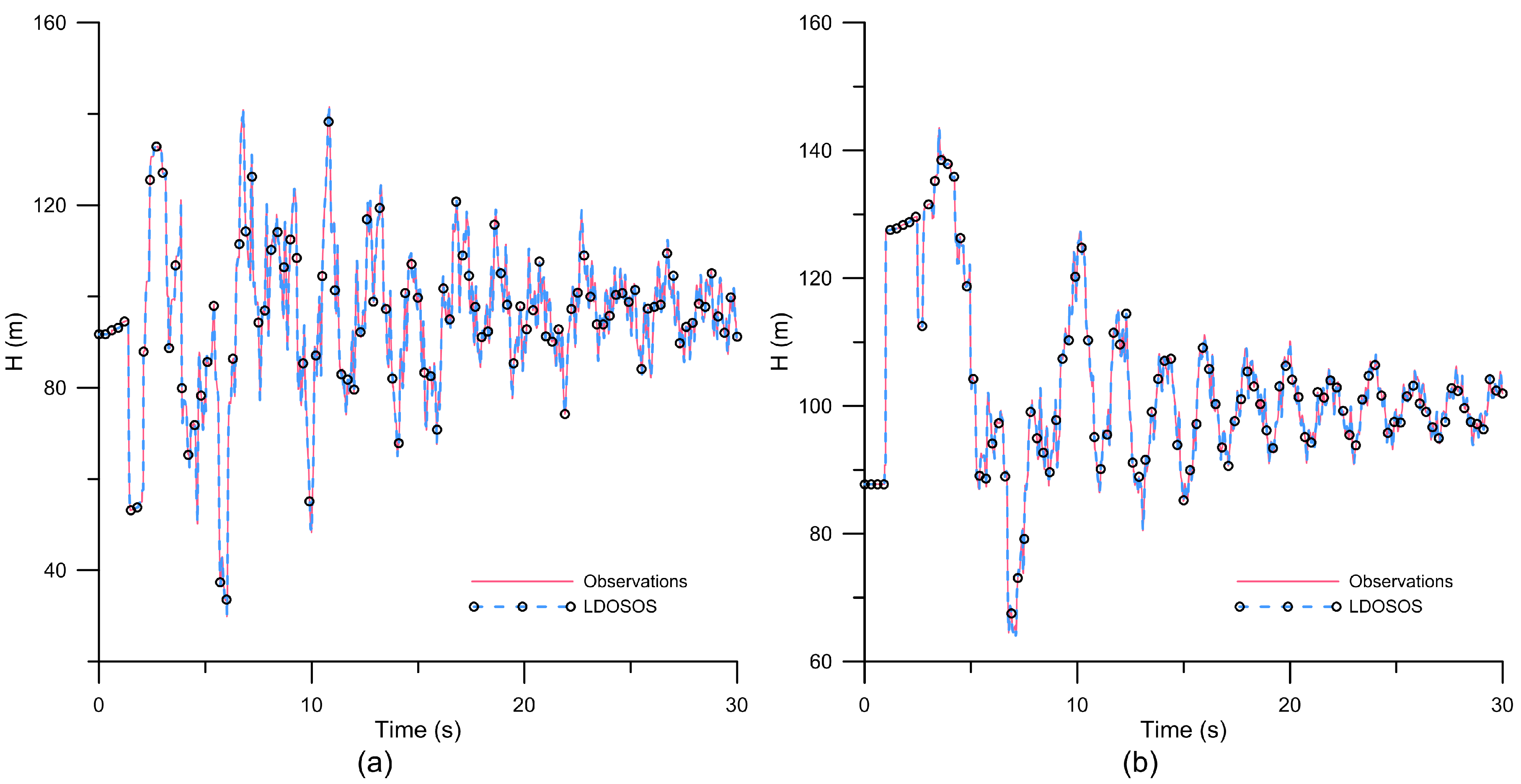
The proposed approach is further used to demonstrate the performance of LDOSOS on leak detection in the WDN. The nodes with several continuity nodal consumptions in the WDN system are considered as the discharge outlet for supplying water to users. To obtain the optimal transient fluctuations in the pipe network, a best generation point is first selected from the feasible locations (i.e., N2, N8, and N9). The initial outflow of the feasible locations is then changed to the triangular form, as shown in Figure 2. The optimal operation parameters, y and z are optimized to generate the worst transient fluctuations, while 1 < y < 10 s and −5 < z < 5 m3/min, with all of the nodal heads being greater than 0 and less than 160 m. The maximum value of Equation (10) with the optimal parameters for each candidate node is listed in Table 4. The overall maximum value reaches to 1978, while using N8 as the transient generation point. The optimum operation duration time y is determined as 2.7 s, while the discharge change z is estimated as −2.58 m3/min. The maximum transient energy of N8 is higher than that of N2 and N9. Thus, the N8 with its relevant parameters is the best point to generate the transient fluctuations for S2. Furthermore, N8 and N9 are considered as the observation and generation point in LDOSOS to compare the leak detection results using different operation points with its relevant parameters. The transient pressures are sampled for 30 s after the excitation.
Figure 8a,b, respectively, show the optimal temporal head distributions observed at N8 and N9 for pipe network B with two potential leaks. The optimal simulated temporal heads at N8 and N9 are precisely reconstructed as compared to the observations. Apparently, the oscillation of transient fluctuation at N8 is heavier than that of N9. Table 5 shows the optimal solutions of the estimated leak information predicted by using N8 or N9 as the transient generation point in LDOSOS. The predicted results clearly demonstrates the ascendancy of the optimal location (N8) as the best transient generation point. Although the leak sizes are quite different to each other, the leaks are successfully detected by the proposed approach in the short time. It takes about 60 min and 1843 iterations to obtain the optimal solution by using N8 to generate transient fluctuations. On the other hand, it took about 64 min and 1967 iterations for using N9 as the generation point. The efficiency between two generation points is not obvious. However, the predicted results of L2 yields about a 3.6% relative error in leak area of L2 while using N9 as the generation point. The accuracy is better when using the optimal generation point N8 with its relevant parameters, which indicates that LDOSOS could be used for leak detection, even though the node continues to supply water to other purposed/use. The results show that the accuracy of the proposed approach increased when using the optimal transient generation point and the optimal operation parameters.

3.4. Measurement Error Analysis

To evaluate the accuracy of the results predicted by proposed approach, two error criteria, standard error of the estimate (SEE) and mean error (ME), are used to assess the influence of measurement error to LDOSOS for leak detection. SEE is the square root of the sum of squared errors between the simulated and computed heads divided by the number of degrees of freedom, which equals the number of observed data points minus the number of unknowns. On the other hand, ME is the average of the sum of errors between the simulated and computed heads. More details on the use of ME and SEE are provided in [58].
Two cases for each scenario are considered in Analysis: 1. 6001 simulated data with high frequency of 0.005 s are used; 2. 601 data with low frequency of 0.05 s with measurement errors are applied. The white noise with zero mean and 0.01 standard deviation are generated and added to those low frequency data to represent the measurement errors. Note that N8 is chosen as the transient generation point for the mentioned cases of S2. Table 6 shows the results of the error analysis for leak detection in those two scenarios with two cases. The error analyses demonstrate slight differences among those two cases in each scenario. The MEs in each Case 1 of those two scenarios are one order smaller than those of Case 2. Furthermore, SEEs in each Case 2 are two orders larger than those of Case 1. Such a result is consistent with the magnitude of noise added to the original simulated data. The results of Case 2 of both scenarios demonstrate that the influence of measurement error is insignificant, implying that LDOSOS can precisely predict the leak information even the observations contained measurement errors.

4. Conclusions

This study presents a hybrid heuristic optimization approach, termed LDOSOS, to detect leaks in pipe networks based on the combination of hydraulic transient flow simulations, OOA and SOS. Leaks in the pipes are represented by orifices. The PNSOS is used to determine the head at each node and the flow rate at each pipe before transient generation. To enhance the efficiency and accuracy of LDOSOS, a procedure is used to estimate the optimal transient generation point and its operation parameters. Moreover, the OOA is applied to sift the searching space. The top 25% CAPs with smaller OFVs are sifted, and the top 5% CASs are selected as the initial organisms for the ecosystem in SOS algorithm. After obtaining the OFVs of the initial organisms, LDOSOS identifies the leaks using three symbiotic states to guide the organisms forward and move toward the variable best organism (Xbest) with the smallest OFV.
A pipe network with two leaks in the same pipe is first used to verify the ability of the proposed approach for leak detection. The temporal head distribution, leak locations, and CdAs are accurately predicted and agreed well with those from the other two algorithms. When these three algorithms are compared, LDOSOS had an approximately 86 and 58% better computing efficiency than LDSA and LDSOS. Moreover, the LDOSOS only takes about 50 min and 1469 iterations to obtain the optimal solution, implying that the searching space is largely reduced by the elimination procedure OOA, and the solutions quickly converged to the optimal solution during iterations. The simulation results show that LDOSOS not only greatly enhances the computation efficiency but also increases the convergence ability. On the other word, LDOSOS significantly outperforms LDSA and LDSOS.
Using ITA for leak detection, the worst transient fluctuations with drastic changes are theoretically essential for good performance of ITA. The optimal transient energy estimation is used in the proposed approach to obtain the optimal transient generation point and its relevant parameters. On the basis of DMA, a WDN is used in this study consisting of 11 pipes, nine nodes, with several continuously outflows, and two potential leaks in two different pipes. The SOS is first used to optimize the operation parameter of three feasible transient generation points. N8 and N9 are then selected to compare the performance of LDOSOS using different transient generation points. The leak information is accurately predicted by LDOSOS with fairly high efficiency by using the best generation point N8 and relevant parameters. The detected results adopting the suboptimal generation point N9 yield a relative error of about 3.6% for the predicted leak area of L2. The results show that the optimal generation point and operation parameters provide more reliable results than other candidate generation points.
In summary, it has been demonstrated from the simulations that LDOSOS has the ability to detect the number of leaking pipe, location of the leak, and their size in a synthetic simple pipe network and a synthetic WDN. The proposed approach speeds up the ITA convergence and improves the reliability of the results. Moreover, the head at measurement point can be precisely computed by LDOSOS even the observations contained measurement errors. However, real drink water systems usually have more complicated pipe and system properties. Pipe characteristics in real situations will also be different if different pipe materials are used. We expect that we will be able improve the capability of LDOSOS to apply to real situations and provide a sound method to detect leaks in pipes in future work.

Acknowledgments

The author appreciates the three anonymous reviewers for comments and thanks Hund-Der Yeh for providing the research resource used in this study. This study was partly supported by the grants from Taiwan Ministry of Science and Technology under the contract number MOST106-2221-E009-066.

Conflicts of Interest

The author declares no conflict of interest.

References

  1. Thornton, J.; Sturm, R.; Kunkel, G. Water Loss Control, 2nd ed.; Mcgraw-Hill: New York, NY, USA, 2008. [Google Scholar]
  2. Lambert, A.O. International report: Water losses management and techniques. Water Sci. Technol. Water Supply 2002, 2, 1–20. [Google Scholar]
  3. Kanakoudis, V.; Tsitsifli, S. Urban water services public infrastructure projects: Turning the high level of the NRW into an attractive financing opportunity using the PBSC tool. Desalin. Water Treat. 2012, 39, 323–335. [Google Scholar] [CrossRef]
  4. Colombo, A.F.; Lee, P.; Karney, B.W. A selective literature review of transient-based leak detection methods. J. Hydro-Environ. Res. 2009, 2, 212–227. [Google Scholar] [CrossRef]
  5. Puust, R.; Kapelan, Z.; Savic, D.A.; Koppel, T. A review of methods for leakage management in pipe networks. Urban Water J. 2010, 7, 25–45. [Google Scholar] [CrossRef]
  6. Al-Khomairi, A. Leak detection in long pipelines using the least squares method. J. Hydraul. Res. 2008, 46, 392–401. [Google Scholar] [CrossRef]
  7. Shamloo, H.; Haghighi, A. Optimum leak detection and calibration of pipe networks by inverse transient analysis. J. Hydraul. Res. 2010, 48, 371–376. [Google Scholar] [CrossRef]
  8. Covelli, C.; Cozzolino, L.; Cimorelli, L.; Della Morte, R.; Pianese, D. A model to simulate leakage through joints in water distribution systems. Water Sci. Technol. Water Supply 2015, 15, 852–863. [Google Scholar] [CrossRef]
  9. Covelli, C.; Cimorelli, L.; Cozzolino, L.; Della Morte, R.; Pianese, D. Reduction in water losses in water distribution systems using pressure reduction valves. Water Sci. Technol. Water Supply 2016, 16, 1033. [Google Scholar] [CrossRef]
  10. Covelli, C.; Cozzolino, L.; Cimorelli, L.; Della Morte, R.; Pianese, D. Optimal location and setting of prvs in wds for leakage minimization. Water Resour. Manag. 2016, 30, 1803–1817. [Google Scholar] [CrossRef]
  11. Juliano, T.M.; Meegoda, J.N.; Watts, D.J. Acoustic emission leak detection on a metal pipeline buried in sandy soil. J. Pipeline Syst. Eng. Pract. 2013, 4, 149–155. [Google Scholar] [CrossRef]
  12. Martini, A.; Troncossi, M.; Rivola, A. Leak detection in water-filled small-diameter polyethylene pipes by means of acoustic emission measurements. Appl. Sci. 2017, 7, 2. [Google Scholar] [CrossRef]
  13. Martini, A.; Troncossi, M.; Rivola, A. Automatic leak detection in buried plastic pipes of water supply networks by means of vibration measurements. Shock Vib. 2015, 2015. [Google Scholar] [CrossRef]
  14. Martini, A.; Troncossi, M.; Rivola, A. Vibroacoustic measurements for detecting water leaks in buried small-diameter plastic pipes. J. Pipeline Syst. Eng. Pract. 2017, 8. [Google Scholar] [CrossRef]
  15. Yazdekhasti, S.; Piratla, K.R.; Atamturktur, S.; Khan, A. Experimental evaluation of a vibration-based leak detection technique for water pipelines. Struct. Infrastruct. Eng. 2017, 1–10. [Google Scholar] [CrossRef]
  16. Zahab, S.E.; Mosleh, F.; Zayed, T. An Accelerometer-Based Real-Time Monitoring and Leak Detection System for Pressurized Water Pipelines; Pipelines: Kansas City, MO, USA, 2016; pp. 257–268. [Google Scholar]
  17. Li, R.; Huang, H.; Xin, K.; Tao, T. A review of methods for burst/leakage detection and location in water distribution systems. Water Sci. Technol. Water Supply 2015, 15, 429–441. [Google Scholar] [CrossRef]
  18. Chaudhry, M.H. Applied Hydraulic Transients, 3rd ed.; Springer: New York, NY, USA, 2014. [Google Scholar]
  19. Vítkovský John, P.; Lambert Martin, F.; Simpson Angus, R.; Liggett James, A. Experimental observation and analysis of inverse transients for pipeline leak detection. J. Water Resour. Plan. Manag. 2007, 133, 519–530. [Google Scholar] [CrossRef]
  20. Vítkovský John, P.; Simpson Angus, R.; Lambert Martin, F. Leak detection and calibration using transients and genetic algorithms. J. Water Resour. Plan. Manag. 2000, 126, 262–265. [Google Scholar] [CrossRef]
  21. Kapelan, Z.S.; Savic, D.A.; Walters, G.A. A hybrid inverse transient model for leakage detection and roughness calibration in pipe networks. J. Hydraul. Res. 2003, 41, 481–492. [Google Scholar] [CrossRef]
  22. Jung, B.S.; Karney, B.W. Systematic exploration of pipeline network calibration using transients. J. Hydraul. Res. 2008, 46, 129–137. [Google Scholar] [CrossRef]
  23. Shamloo, H.; Haghighi, A. Leak detection in pipelines by inverse backward transient analysis. J. Hydraul. Res. 2009, 47, 311–318. [Google Scholar] [CrossRef]
  24. Haghighi, A.; Ramos, H.M. Detection of leakage freshwater and friction factor calibration in drinking networks using central force optimization. Water Resour. Manag. 2012, 26, 2347–2363. [Google Scholar] [CrossRef]
  25. Huang, Y.-C.; Lin, C.-C.; Yeh, H.-D. An optimization approach to leak detection in pipe networks using simulated annealing. Water Resour. Manag. 2015, 29, 4185–4201. [Google Scholar] [CrossRef]
  26. Liggett, J.A.; Chen, L.C. Inverse transient analysis in pipe networks. J. Hydraul. Eng. 1994, 120, 934–955. [Google Scholar] [CrossRef]
  27. Ferrante, M.; Brunone, B.; Meniconi, S. Leak detection in branched pipe systems coupling wavelet analysis and a lagrangian model. J. Water Supply Res. Technol. AQUA 2009, 58, 95. [Google Scholar] [CrossRef]
  28. Nazif, S.; Karamouz, M.; Tabesh, M.; Moridi, A. Pressure management model for urban water distribution networks. Water Resour. Manag. 2010, 24, 437–458. [Google Scholar] [CrossRef]
  29. Ferrante, M.; Brunone, B.; Meniconi, S.; Karney, B.W.; Massari, C. Leak size, detectability and test conditions in pressurized pipe systems. Water Resour. Manag. 2014, 28, 4583–4598. [Google Scholar] [CrossRef]
  30. Casillas, V.M.; Garza-Castañón, E.L.; Puig, V. Optimal sensor placement for leak location in water distribution networks using evolutionary algorithms. Water 2015, 7, 6496–6515. [Google Scholar] [CrossRef] [Green Version]
  31. Meniconi, S.; Brunone, B.; Ferrante, M.; Capponi, C.; Carrettini, C.A.; Chiesa, C.; Segalini, D.; Lanfranchi, E.A. Anomaly pre-localization in distribution–transmission mains by pump trip: Preliminary field tests in the milan pipe system. J. Hydroinform. 2015, 17, 377–389. [Google Scholar] [CrossRef]
  32. Lee, S.J.; Lee, G.; Suh, J.C.; Lee, J.M. Online burst detection and location of water distribution systems and its practical applications. J. Water Resour. Plan. Manag. 2016, 142, 04015033. [Google Scholar] [CrossRef]
  33. Soares, A.K.; Covas, D.I.C.; Reis, L.F.R. Leak detection by inverse transient analysis in an experimental pvc pipe system. J. Hydroinform. 2011, 13, 153–166. [Google Scholar] [CrossRef]
  34. Casillas Ponce, M.V.; Garza Castañón, L.E.; Cayuela, V.P. Model-based leak detection and location in water distribution networks considering an extended-horizon analysis of pressure sensitivities. J. Hydroinform. 2014, 16, 649–670. [Google Scholar] [CrossRef]
  35. Yeh, H.-D.; Lin, Y.-C. Pipe network system analysis using simulated annealing. J. Water Supply Res. Technol. AQUA 2008, 57, 317–327. [Google Scholar] [CrossRef]
  36. Mays, L.W. Water Supply Systems Security; McGraw-Hill: New York, NY, USA, 2004. [Google Scholar]
  37. Savić, D.A.; Banyard, J.K. Water Distribution Systems, 2nd ed.; ICE: London, UK, 2011. [Google Scholar]
  38. Larock, B.E.; Jeppson, R.W.; Watters, G.Z. Hydraulics of Pipeline Systems; CRC Press: Boca Raton, FL, USA, 2000. [Google Scholar]
  39. Vítkovský, J.; Stephens, M.; Bergant, A.; Simpson, A.; Lambert, M. Numerical error in weighting function-based unsteady friction models for pipe transients. J. Hydraul. Eng. 2006, 132, 709–721. [Google Scholar] [CrossRef]
  40. Duan, H.-F.; Ghidaoui, M.; Lee, P.J.; Tung, Y.-K. Unsteady friction and visco-elasticity in pipe fluid transients. J. Hydraul. Res. 2010, 48, 354–362. [Google Scholar] [CrossRef]
  41. Vítkovský, J.P.; Bergant, A.; Simpson, A.R.; Lambert, M.F. Systematic evaluation of one-dimensional unsteady friction models in simple pipelines. J. Hydraul. Eng. 2006, 132, 696–708. [Google Scholar] [CrossRef]
  42. Reddy, H.P.; Silva-Araya, W.F.; Chaudhry, M.H. Estimation of decay coefficients for unsteady friction for instantaneous, acceleration-based models. J. Hydraul. Eng. 2012, 138, 260–271. [Google Scholar] [CrossRef]
  43. Boulos, P.F.; Lansey, K.E.; Karney, B.W. Comprehensive Water Distribution Systems Analysis Handbook for Engineers and Planners, 2nd ed.; MWH Soft, Incorporated: Pasadena, CA, USA, 2006. [Google Scholar]
  44. Brunone, B. Transient test-based technique for leak detection in outfall pipes. J. Water Resour. Plan. Manag. 1999, 125, 302–306. [Google Scholar] [CrossRef]
  45. Meniconi, S.; Brunone, B.; Ferrante, M.; Massari, C. Small amplitude sharp pressure waves to diagnose pipe systems. Water Resour. Manag. 2011, 25, 79–96. [Google Scholar] [CrossRef]
  46. Brunone, B.; Ferrante, M.; Meniconi, S. Portable pressure wave-maker for leak detection and pipe system characterization. J. Am. Water Works Assoc. 2008, 100, 108–116. [Google Scholar]
  47. Shucksmith, J.D.; Boxall, J.B.; Staszewski, W.J.; Seth, A.; Beck, S.B.M. Onsite leak location in a pipe network by cepstrum analysis of pressure transients. J. Am. Water Works Assoc. 2012, 104, E457–E465. [Google Scholar] [CrossRef]
  48. Stephens, M.L.; Lambert, M.F.; Simpson, A.R. Determining the internal wall condition of a water pipeline in the field using an inverse transient. J. Hydraul. Eng. 2013, 139, 310–324. [Google Scholar] [CrossRef]
  49. Taghvaei, M.; Beck, S.B.M.; Boxall, J. Leak detection in pipes using induced water hammer pulses and cepstrum analysis. Int. J. COMADEM 2010, 13, 19–25. [Google Scholar]
  50. Haghighi, A.; Shamloo, H. Transient generation in pipe networks for leak detection. Proc. Inst. Civ. Eng. Water Manag. 2011, 164, 311–318. [Google Scholar] [CrossRef]
  51. Ho, Y.C.; Cassandras, C.G.; Chen, C.H.; Dai, L. Ordinal optimisation and simulation. J. Oper. Res. Soc. 2000, 51, 490–500. [Google Scholar] [CrossRef]
  52. Lau, T.W.E.; Ho, Y.C. Universal alignment probabilities and subset selection for ordinal optimization. J. Optim. Theory Appl. 1997, 93, 455–489. [Google Scholar] [CrossRef]
  53. Cheng, M.-Y.; Prayogo, D. Symbiotic organisms search: A new metaheuristic optimization algorithm. Comput. Struct. 2014, 139, 98–112. [Google Scholar] [CrossRef]
  54. Cheng, M.-Y.; Prayogo, D.; Tran, D.-H. Optimizing multiple-resources leveling in multiple projects using discrete symbiotic organisms search. J. Comput. Civ. Eng. 2016, 30, 04015036. [Google Scholar] [CrossRef]
  55. Tran, D.-H.; Cheng, M.-Y.; Prayogo, D. A novel multiple objective symbiotic organisms search (mosos) for time–cost–labor utilization tradeoff problem. Knowl-Based. Syst. 2016, 94, 132–145. [Google Scholar] [CrossRef]
  56. Bozorg-Haddad, O.; Azarnivand, A.; Hosseini-Moghari, S.-M.; Loáiciga, H.A. Optimal operation of reservoir systems with the symbiotic organisms search (SOS) algorithm. J. Hydroinform. 2017, 19, 507–521. [Google Scholar] [CrossRef]
  57. Abhulimen, K.E.; Susu, A.A. Liquid pipeline leak detection system: Model development and numerical simulation. Chem. Eng. J. 2004, 97, 47–67. [Google Scholar] [CrossRef]
  58. Yeh, H.-D. Theis’ solution by nonlinear least-squares and finite-difference newton’s method. Ground Water 1987, 25, 710–715. [Google Scholar] [CrossRef]
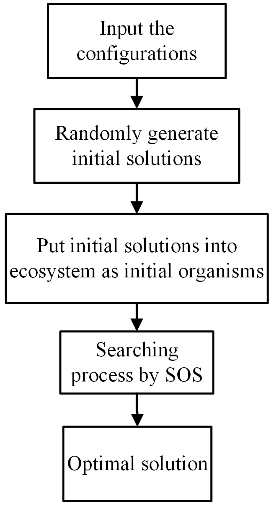
Figure 1. Flowchart of pipe network analysis model (PNSOS).
Water 09 00812 g001
Figure 2. Transient excitation at operation point.
Water 09 00812 g002
Figure 3. Flowchart of symbiotic organism search (SOS).
Water 09 00812 g003
Figure 4. Flowchart of leak detection ordinal symbiotic organism search (LDOSOS).
Water 09 00812 g004
Figure 5. Configuration of synthetic pipe network A.
Water 09 00812 g005
Figure 6. Configuration of synthetic pipe network B.
Water 09 00812 g006
Figure 7. The simulated head distributions at valve for leak detection using various approaches.
Water 09 00812 g007
Figure 8. Simulated head distributions observed at (a) N8 and (b) N9.
Water 09 00812 g008
Table 1. The characteristics of the synthetic pipe network A.
PipeNodeDiameter (mm)Length (m)
NumberFromTo
P1N1N2305.01000.0
P2N2N3305.01000.0
P3N3N4250.01100.0
P4N1N4405.01250.0
P5N4N5355.01000.0
P6N5N6305.01100.0
P7N3N6305.01250.0
P8N6Valve500.01000.0
Table 2. The characteristics of the synthetic pipe network B.
PipeNodeDiameter (mm)Length (m)
NumberFromTo
P1N1N2305.01000.0
P2N2N3305.01000.0
P3N3N4250.01100.0
P4N1N4405.01250.0
P5N4N5200.0500.0
P6N5N6400.0400.0
P7N7N6200.0500.0
P8N4N7355.0400.0
P9N7N8355.0600.0
P10N8N9305.01100.0
P11N3N9305.01250.0
Table 3. Actual leak information and predicted results from three approaches for S1.
HeaderL1L2CPU Time (min)Iterations
Pipe No.Location (m)CdA × 10−4 (m2)Pipe No.Location (m)CdA × 10−4 (m2)
Actual63002.563102.5--
LDSA63002.563102.53729815
LDSOS63002.563102.51203481
LDOSOS63002.563102.5501469
Table 4. Optimum operation parameters for candidate nodes.
Nodey (s)z (m3/min)EMax
N27.2−5.01239
N82.7−2.581978
N93.6−3.221843
Table 5. Estimated leak information for S2 using N8 or N9.
HeaderN8N9
L1L2L1L2
Pipe No.Location (m)CdA × 10−4 (m2)Pipe No.Location (m)CdA × 10−4 (m2)Pipe No.Location (m)CdA × 10−4 (m2) Pipe No.Location (m)CdA × 10−4 (m2)
Actual113002.572501113002.572501
LDOSOS113002.49972501113002.47972500.964
Note that the computation time are 60 min and 64 min for using N8 and N9, respectively.
Table 6. The prediction errors of leak detection in two scenarios.
Prediction Errors
Scenario 1ME (m)SEE (m)
Case 1−1.76 × 10−64.11 × 10−4
Case 21.35 × 10−55.63 × 10−2
Scenario 2ME (m)SEE (m)
Case 16.13 × 10−68.13 × 10−4
Case 27.41 × 10−56.58 × 10−2