Article

Experimental Investigations of Scour Pools around Porous Obstructions

1
Hydro Science and Engineering Research Institute, Korea Institute of Civil Engineering and Building Technology, Goyang 411-712, Korea
2
Division of Field Engineering for Environment, Hokkaido University, Sapporo 060-8628, Japan
*
Author to whom correspondence should be addressed.
Water 2016, 8(11), 498; https://doi.org/10.3390/w8110498
Submission received: 4 August 2016 / Revised: 24 October 2016 / Accepted: 24 October 2016 / Published: 1 November 2016

Abstract

:
Paired impermeable or porous obstructions are used to create scour pool habitat. We investigated local scour pools created by paired porous obstructions using laboratory experiments. To examine the influence of porous obstructions on local scour depths and volumes, various densities in the porous obstructions, ratio of obstruction width to channel width and submergence ratio were evaluated. A local scour pool developed when the flow blockage (product of density in the porous obstructions and ratio of obstruction width to channel width) and the ratio of the obstruction width to channel width were ≥5.0 and ≥0.4, respectively. The depth of the scour pool increased with increasing flow blockage, while scour depth reduced as the submergence ratio increased. The scoured volume had a strong relationship with the scour depth around the porous obstructions. Results of the predictive equations were considered reliable for estimating the maximum scour depth and scoured volume around porous obstructions in clear-water conditions.

1. Introduction

In the past, channels were straightened to prevent flooding but it caused the destruction of riverine ecosystems [1]. Recently, stream restoration works have been extensively conducted to return degraded ecosystem and natural functions [1,2]. One of the main objectives of these works is to create locally varied flow conditions, and promote scour pools and riffles. There are a lot of instream habitat structures such as deflectors, rock vanes, and spur dikes. A usual design of instream habitat structure is the use of flow deflectors, which are recognized as one of the best tools for habitat restoration techniques [3,4]. Deflectors provide various flow conditions by constricting and diverting the water, thereby enhancing ecosystem diversity. Consequently, local scour is developed around the deflector, so that scour pools are created. The scour pools are characterized by deep water depth and slow current. Gorman and Karr [5] observed that water depth and current velocity have a strong relationship with species and habitat diversity. The scour pools can offer favorable places for fishes because they can hold and feed during low flow conditions, and take refuge during high flow conditions [6]. In order to successfully plan, design, and construct restoration projects that provide a variety of flow conditions and favorable habitats for fishes, two parameters should be considered: (i) maximizing scour pool habitat and (ii) minimizing potential for bank scour [3,7].
There are many studies on size and location of scour pools caused by single deflectors and spur dikes in terms of orientation, height, and length. Thompson [8] conducted flume experiments on the effect of scour pools at low and high deflectors, and concluded that high deflectors have been proven much more useful to create scour pool habitat. Some previous research reported that the orientation of deflectors is associated with the volume of scour pools [3,7,9]. Maximum scour was observed at spur dikes oriented perpendicular to the flow [3]. The dikes oriented downstream caused less turbulence and local scour, and thus downstream orientation reduced scour pool volume and depth [9]. In addition, downstream orientation of dikes triggers the flow to be directed to banks, thereby requiring more protection on the banks. Rodrigue-Gervais et al. [4] examined the impact of submergence ratio (flow depth/deflector height) on scour holes around paired impermeable deflectors. When the submergence ratio increased, the depth and volume of scour holes decreased. Biron et al. [3] investigated characteristics of scour holes in terms of the angle, height, and length of paired impermeable deflectors which are installed on each bank of a channel. The deflectors oriented upstream and downstream resulted in 26%~30% and 5%~10% smaller scour depths than deflectors that were normal to the banks, respectively. The scoured volume and potential for bank erosion increased as the submergence ratio decreased.
Most studies have used impermeable single and paired structures, and have evaluated the orientation, height, and length of the deflectors, including the ratio of the length of the deflector to the channel width (i.e., the contraction ratio). Recently, to restore more natural streams, porous obstructions such as vegetation have been advocated for use, because they not only create scour holes but also improve water quality by removing contaminants [10]. Bennett et al. [1] conducted laboratory experiments in a flume using fine sands within a compound channel. Porous obstructions were placed alternately along the channel, affecting the flow and bed morphology. They observed that the channel response was significantly influenced by density of the porous obstructions and that the obstructions could be used to adjust the meander wavelengths and scour depth of pools in a straight channel. Kim et al. [11] showed that the depth of scour holes increases as the density and width of porous obstructions increase.
Studies using laboratory flumes have developed empirical or dimensionless equations to predict maximum scour depth and scour volume near impermeable structures [3,7]. Thompson [8] proposed functions for pool volume and depth around single impermeable structures. Rodrigue-Gervais et al. [4] obtained predictive equations for depth and volume of scour pools associated with paired structures. Kang et al. [12] investigated flow patterns around single spur dikes and permeability effects. Nepf [13] showed some results of flow characteristics around single porous structures and examined the effect of submergence ratio and density on flow fields and sediment transport. To our knowledge, scour pools and volume around paired porous structures for habitat restoration have not yet been investigated.
In this study, we investigated the influence of the density and contraction ratio of paired porous obstructions on the development of scour pools using laboratory experiments (Figure 1). Simple rectangular paired porous obstructions consisting of circular cylinders in a staggered array were used in a straight open channel, placed along both side walls. In the laboratory experiments, we varied the ratio of the obstruction width to the channel width and submergence along with various densities of porous obstructions under flow conditions below the threshold of sediment motion. Changes in the bed topography around the paired porous obstructions were observed and the impacts of the density, contraction ratio, and submergence ratio on the depth and volume of local scour pools were analyzed.

2. Experimental Setup

Laboratory experiments were conducted in a flume 10 m long (L), 0.4 m wide (W), and 0.4 m deep with Plexiglas side walls, and a recirculating flume in which sediment is not recirculated (Figure 2). The flow rate was controlled at a rate of 0.0032 m3/s by a manual valve. Initially, a low flow rate was used to saturate the sand bed and avoid scouring. A plastic mesh screen was installed to minimize water-surface oscillation and remove large-scale disturbances at the upstream entrance to the channel. The channel slope was set to 1/800. The water depth was measured at 0.05 m upstream from obstructions (x = 2.35 m). Based on flow depth at x = 2.35 m, the Froude number was from 0.26 to 0.49, which indicates that all experiment cases were carried out at a subcritical flow.
The rectangular shape of paired obstructions was constructed using circular aluminum cylinders 5 mm in diameter (D) and bamboo sticks 2.5 mm in diameter (D) in a staggered array. In the flume, the porous obstructions were either emergent or submerged, to test both conditions (emergent: h/hp = 1.0, submerged: h/hp = 1.6, where h and hp are the water depth and height of the obstructions, respectively). The leading edges of the obstructions were positioned 2.4 m downstream of the channel entrance based on a previous experiment [3] and empirical equation [14] (Figure 2). In Daily and Harleman [14], the entrance length for fully developed flow can be estimated by empirical equation which is in the range of 50 to 100 water depth. In the experiment of Biron et al. [3], the obstructions were located 2.1 m downstream of the entrance. Thus, the entrance length in this experiment was adequate. To investigate the effect of the ratio of the obstruction width to the channel width, four obstruction widths (0.04, 0.08, 0.12, and 0.16 m) were considered, corresponding to ratios of the obstruction width to the channel width 2Wv/W of 0.2, 0.4, 0.6, and 0.8. Density in the porous obstruction was described by a frontal area per unit volume a (m−1). In this study, various densities in the porous obstructions were tested from 5.6 to 25.0 m−1. The experimental parameters for the obstructions are summarized in Table 1. Thus, the experiments for determining how the density of the porous obstructions, the ratio of obstruction width to channel width (2Wv/W), and submergence ratio (h/hp) affect scour pool dimensions were carried out. In addition, experiments on scour pools forming around paired impermeable obstructions were conducted to compare the development of scour pools around paired porous and impermeable obstructions.
The flume was filled with a 20-cm layer of sediment with a median diameter of 0.76 mm. Before each case, the sand was smoothed with a rigid plastic board and the sediment beds in the porous obstructions were manually smoothed to set similar initial conditions for each case. The flow condition was below the threshold of sediment motion, such that there was no sediment transport upstream of the obstructions (τ**c = 0.88), where τ*c was obtained using Iwagaki’s formula [15]. Therefore, sediment transport was only induced by the porous obstructions. This indicates that recirculation of sediment is not required.
The experiments were conducted until maximum scour depth reached steady state. Preliminary 12-h tests for three cases (Exp No. 4, 5, 12) were carried out to determine the duration of experimental runs (Figure 3). The result showed that approximately 95% of the maximum scour depth (ds) normalized by scour depth value at the end of the runs (dse) was achieved at t/te = 0.7, where t is the time and te is the steady state time. Thus, the experiments lasted for a duration of 10-h, which is sufficient to develop scour depth around paired porous obstructions. The bed elevation was measured using a laser bed profiler (IL-065, Keyence, Corporation, Itasca, IL, USA) mounted on the flume. After each experiment, the flow was stopped and the water was allowed to drain slowly to avoid changes in bed topography. The bed elevation was measured every 5.0 and 0.3 cm in the longitudinal and lateral directions, respectively, except in and near the obstructions (2.3 m to 2.8 m downstream), where the measurement was conducted every 2.5 cm in the longitudinal direction. The scans were interpolated and plotted using Surfer 10.0 software (Golden Software, Golden, CO, USA). Changes in the bed topography were identified based on differences between the bed elevations before and after the experiment.

3. Results and Discussion

3.1. Changes in Bed Topography

Morphological responses to porous obstructions in an open channel are associated with density in the obstructions and the ratio of the obstruction width to the channel width. However, solid obstructions of the same size as porous obstructions result in different morphological behaviors. To investigate these differences in morphological changes between solid and porous obstructions, we first observed morphological behavior around solid obstructions.
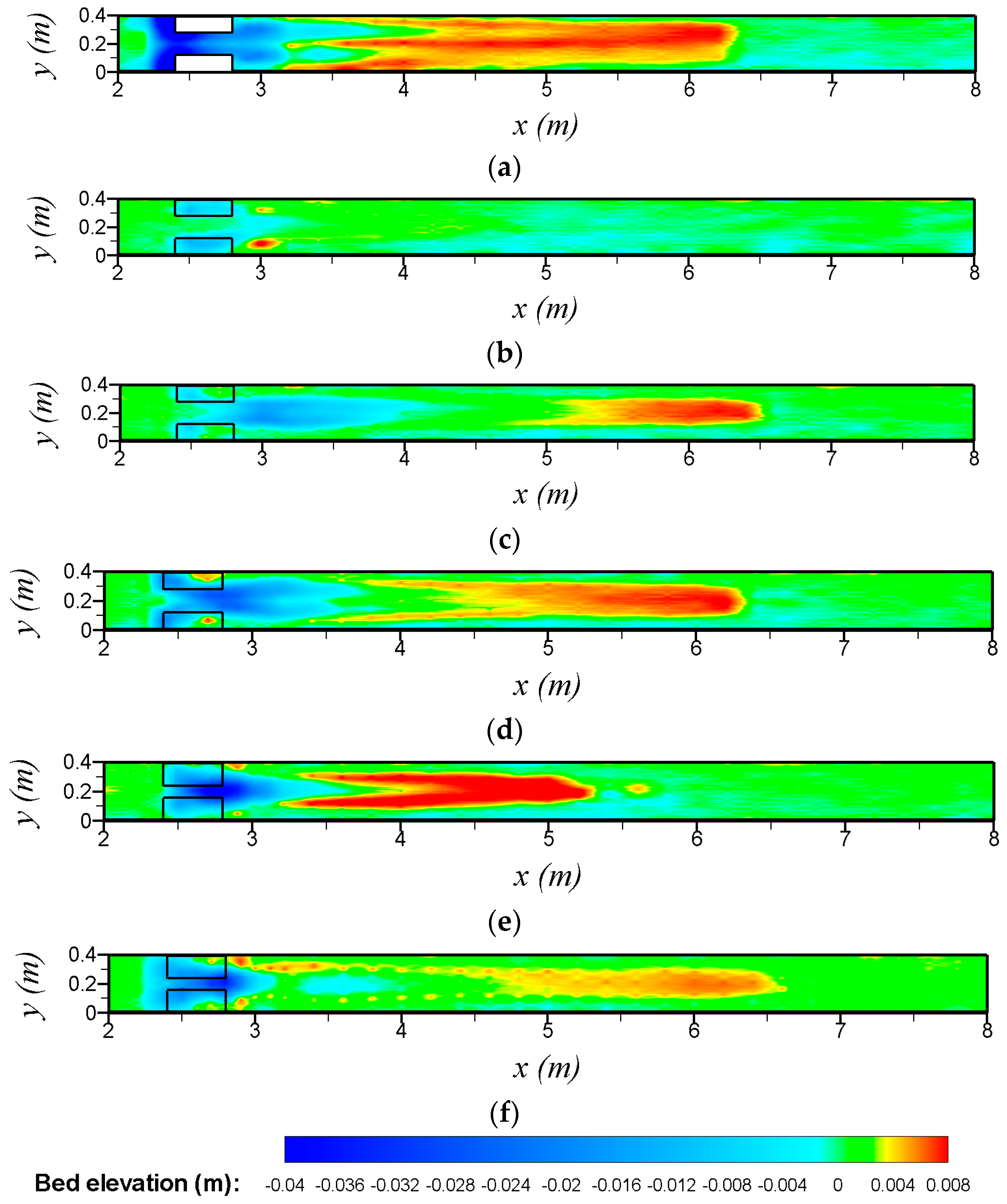
Figure 4a shows changes in the bed topography around emergent solid obstructions with a width of 0.08 m and a length of 0.4 m. Significant local scour was observed in front of the solid obstructions, extending upstream and to the sides of the obstructions. Relatively little erosion took place between the solid obstructions and the sediment was deposited downstream of the obstructions. Changes in the bed topography was observed for various flow blockage, which is a parameter defined by the product of the density in the porous obstructions and the ratio of the obstruction width to channel width (2aWv/W), as shown in 
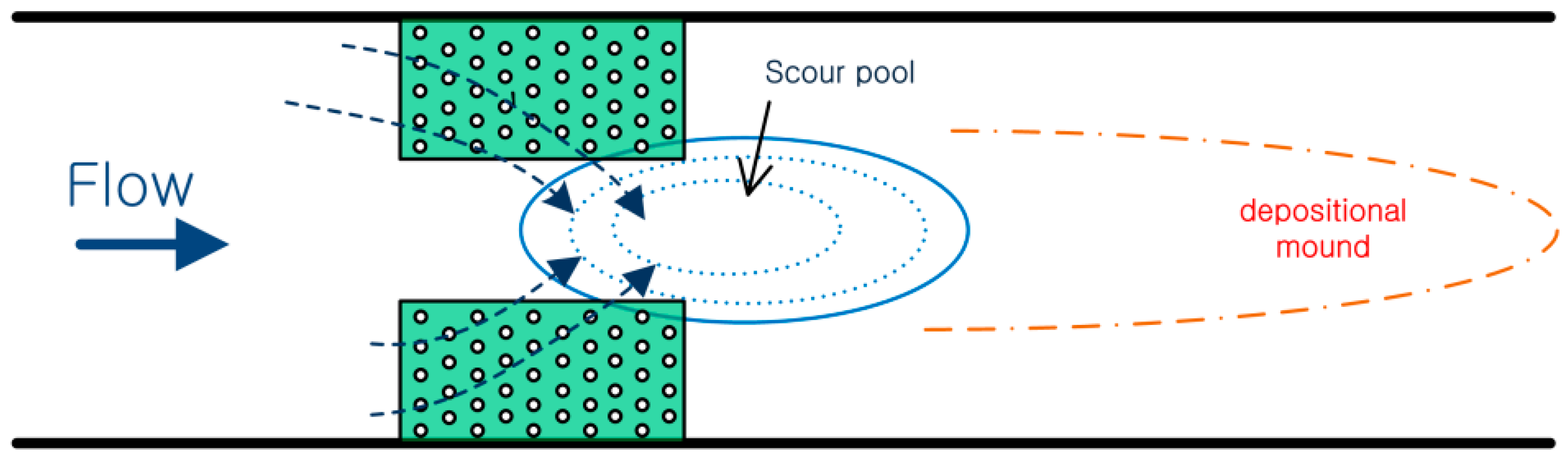
Figure 4. As in the experimental results, the scour and deposition patterns for the porous obstructions differed substantially from those observed for the solid obstructions. Local scouring near the leading edge of the obstructions was significantly weaker or not observed. When local scour was observed near the leading edge, scour also occurred inside the porous obstructions, because the flow penetrated through the obstructions. In addition, unlike the scour patterns for the solid objects, high local erosion was observed between or downstream of the obstructions, creating scour pools in the open channel. These results imply that the flow that diverted around the porous obstructions converges in the small region between the obstructions and that the flow velocity increased (Figure 4). For 2aWv/W = 2.5 (a = 6.25 m−1), a local scour pool did not develop between the porous obstructions, although some scour was observed near and within each obstruction, indicating that the effect of contraction was negligible. For 2aWv/W = 5.0 (a = 12.5 m−1), a local scour pool appeared between and downstream of the porous obstructions. For higher flow blockage (2aWv/W = 10.0), a local scour pool not only was observed, but also merged with the local scour at the leading edge of the obstructions induced by diversion of the flow and elevated turbulence. As the scour pool developed, its depth increased with increasing flow blockage. Based on analysis of the experimental results, a scour pool developed when the flow blockage 2aWv/W was approximately >5.0 because the flow accelerated through the contraction. A local scour pool did not develop when the ratio of the obstruction width to the channel width 2Wv/W was <0.4 because the flow induced by the obstructions was independent [16]. We found that the scoured region induced by acceleration of the flow moved further downstream as the flow blockage decreased. In addition, for same flow blockage, smaller scour depth was observed when the submergence ratio increased (Figure 4e,f). The scour depth was approximately 1.2 times greater for h/hp = 1.0 for 2aWv/W = 20.0.

3.2. Lateral Bed Variaion near the Porous Obstructions

Section 3.1 describes development of local scour pools between or downstream of porous obstructions, which can provide aquatic habitat. However, high local erosion may affect the stability of the porous obstructions. Therefore, to understand the influence of flow blockage on the local scour pools and stability of the porous obstructions, we observed local erosion around the obstructions.
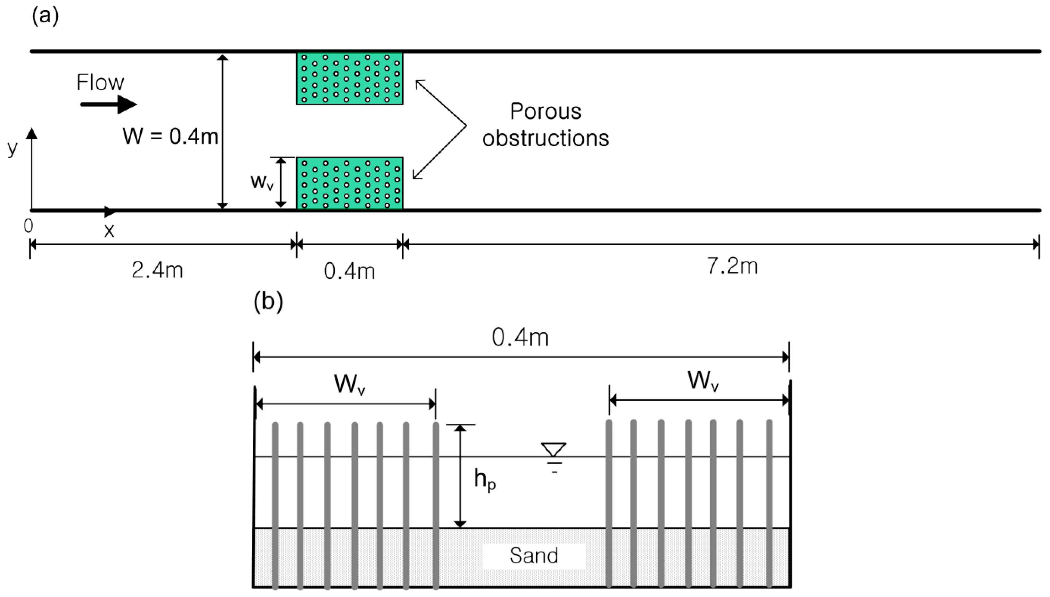
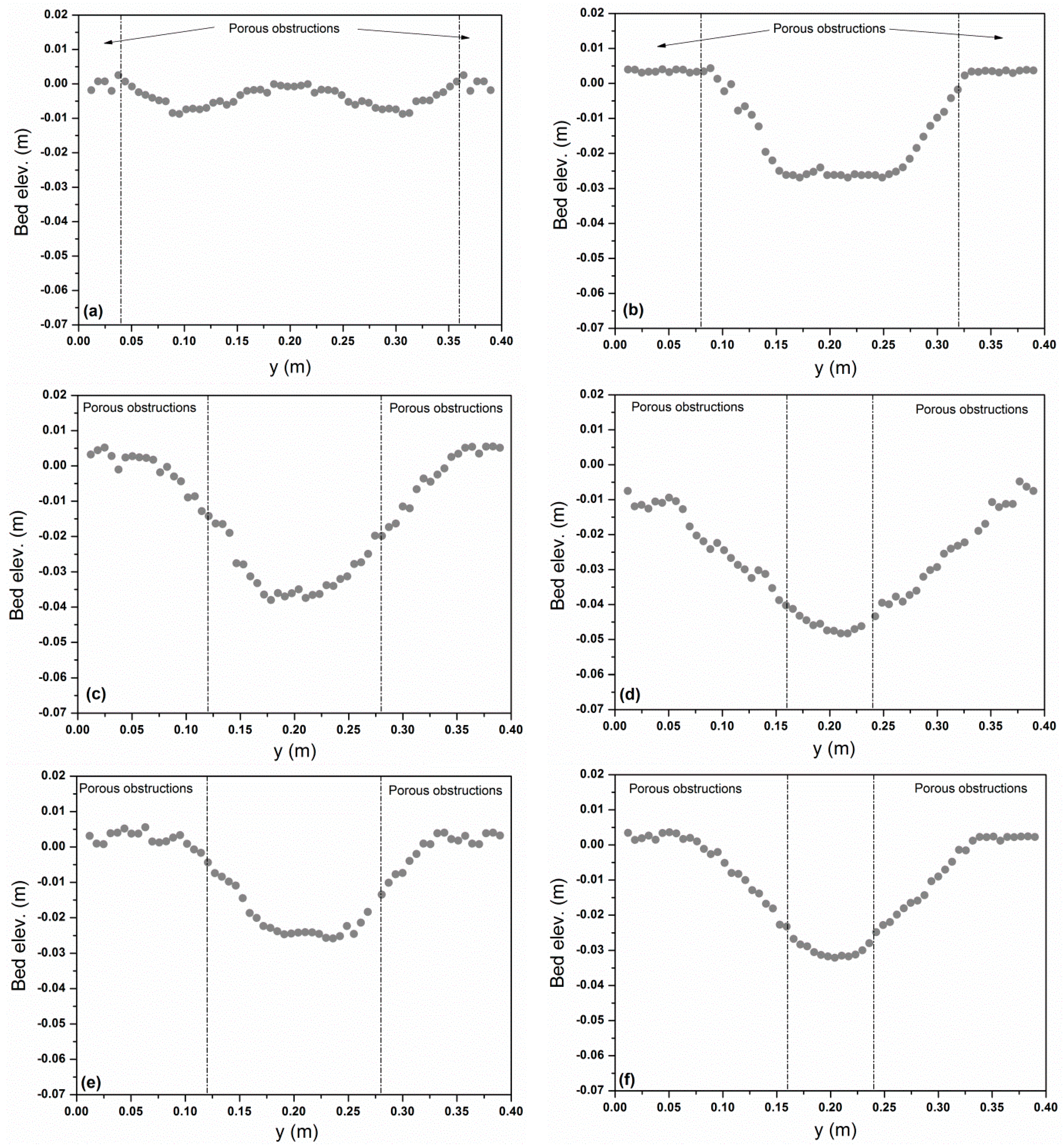
Figure 5 compares the lateral bed profiles for various flow blockages and submergence ratio of porous obstructions at x = 2.55 m, near the middle of the porous obstructions. For 2aWv/W = 5.0 (a = 25 m−1, h/hp = 1.0), erosion was observed near the lateral edges of the obstructions, while the bed elevation remained unchanged near the center of the channel. These results imply that there is no effect of contraction, and thus local scouring occurred independently. Local scour pools formed between the obstructions and their depths increased with increasing flow blockage (Figure 5b–d). These results confirm that a scour pool is created between obstructions when the ratio of the width of the obstructions to the channel width is ≥0.4 and the flow blockage is ≥5.0. Localized scour was accompanied by an expansion of lateral erosion due to an excessive submerged angle of repose (Figure 5). Local scour between the obstructions results in a steep bed slope, so that the sediment particles slide down until the local bed slope becomes stable. The extent of lateral erosion increased with increasing flow blockage; particularly for 2aWv/W = 20.0 (a = 25 m−1, h/hp = 1.0), considerable lateral erosion was observed within the obstructions. Such extensive erosion within the obstructions may expose the structure of the foundation bed, causing instability in the obstructions and possible collapse of obstructions. Similar patterns of local scour between the obstructions for h/hp = 1.6 were observed, and the degree of scour was almost influenced by the flow blockage, indicating that local scour pools were created due to an increase in the bed shear stress resulting from acceleration of flow between obstructions. For 2aWv/W = 20.0 (a = 25 m−1, h/hp = 1.6), although the porous obstructions were submerged, lateral erosion was observed expanding into the obstructions. Thus, lateral erosion affecting the stability of the obstructions is strongly influenced by the ratio of the obstruction width to the channel width.

3.3. Scour Pool

In the experimental data, scour pools were observed between the porous obstructions due to flow acceleration, and the degree of scour increased with the flow blockage (Figure 5). 
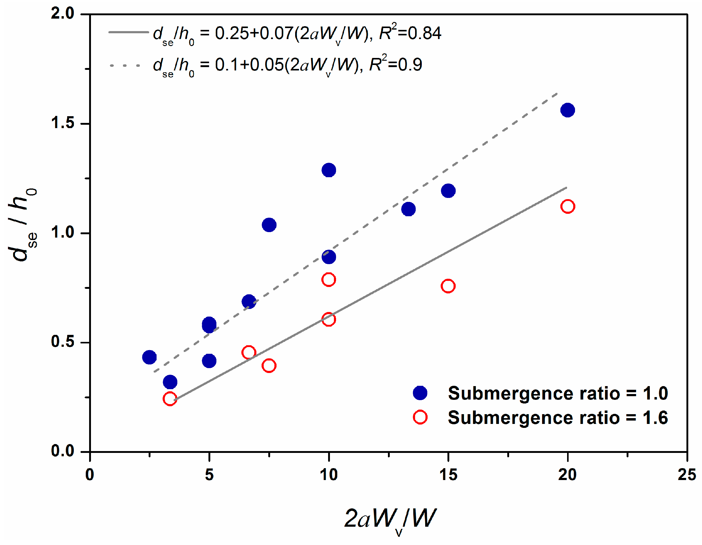
Figure 6 shows the maximum scour depth dse at steady state versus the flow blockage, where the scour depth is normalized by the water depth at the upstream entrance h0. In this figure, an increase in scour depth is indicated by a positive value, and the dashed and solid linear lines are fitted to scour depth in order to emphasize their difference.
When a scour pool was not created, maximum scour depth was observed around the leading edge of the obstructions. On the other hand, the maximum value was found at the scour pool as the scour pool was created. For lower flow blockage (2aWv/W < 5.0), the scour depth was similar for h/hp = 1.0 and 1.6. However, for the flow blockage of 2aWv/W ≥ 5.0, scour depth for h/hp = 1.0 was deeper than that for h/hp = 1.6. We found that as scour pools developed between and downstream of the obstructions, the depth of the scour pool increased with the flow blockage. The maximum scour depth was also affected significantly by the submergence ratio, which was similar to the result of Biron et al. [3].
Local scour pools are beneficial to stream ecosystems, so the scoured regions associated with the porous obstructions are advantageous. The scour regions produced by the obstructions have many environmental benefits; they provide not only aquatic habitat, but also shelter for fish in the event of flooding [6]. 
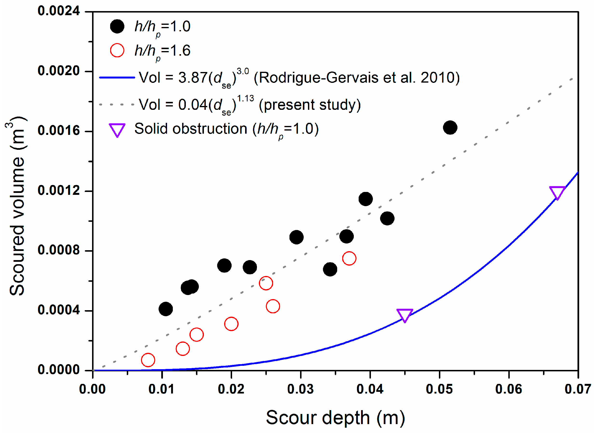
Figure 7 shows the scoured volume around the porous obstructions with the maximum depth of the scour pool. To determine whether there was a strong relationship between the scoured volume and scour depth, a regression analysis was performed. For solid obstructions, Rodrigue-Gervais et al. [4] proposed a predictive equation in which the scoured volume around the solid obstructions increased with scour depth to the power of 3.0. The present experimental results for the solid obstructions were consistent with the predictive equation proposed by Rodrigue-Gervais et al. [4]. However, as described in Section 3.1, the scour pattern around the porous obstructions was quite different from that for the solid obstructions, due to different scour mechanisms. For solid obstructions, scour is locally developed around each obstruction due to acceleration and horseshoe vortices [17]. On the other hand, for porous obstructions, incoming flow can penetrate through porous obstructions. Thus, some flow continues through the obstructions or is diverted away from the obstructions. The diversion of flow and small-scale turbulence induce scour within and around the obstructions [11]. In the experiments, the scoured volume increased with increasing scour depth to the power of 1.13 regardless of the submergence ratio with a coefficient of determination of 0.75 (Figure 7):
Vol = 0.04(dse)1.13
Our results reveal that an increase in the flow blockage (2aWv/W) results in greater depth and volume of scour pools. It can be seen that there is a dissemblance in the scour behavior according to the flow blockage. When 2aWv/W < 5.0 and 2Wv/W < 0.4, a scour pool is not created. Local scour only occurs next to the porous obstructions and the greater scour depth is observed at the edge of the obstructions due to higher edge velocity. For 2aWv/W ≥ 5.0 and 2Wv/W ≥ 0.4, the scour pool is created between the paired obstructions and maximum scour depth always takes place at the scour pool. For 2aWv/W ≥ 5.0 and 2Wv/W ≥ 0.4, the flow accelerates between the porous obstructions and the flow becomes greater with an increase in the flow blockage, which is related to a flow diversion [11,12,18]. When the flow blockage increases, the diverging flow from the porous obstructions increases due to higher drag, leading to greater magnitude of the velocity and turbulence at the center of the channel. In particular, the flow between paired obstructions is similar to a turbulent jet at higher flow blockage [16].
Another key finding is an influence of submergence ratio on the scour pool. The submergence ratio of the porous obstructions affects the potential to create a scour pool, and thus a lower ratio increases the depth and volume of a scour pool. This is in agreement with the results of Thompson [8], Biron et al. [3], and Rodrigue et al. [4] who concluded that the extent and depth of scour decrease with an increase in submergence ratio at the same discharge and approaching flow depth, even though they conducted experiments with impermeable paired obstructions. The porous obstructions with h/hp = 1.0 generate a high velocity at the edge due to flow deflection in the horizontal plane. However, for h/hp = 1.6, flow is vertically deflected as well. If more flow is deflected over the obstructions, the acceleration of flow decreases at a contraction region [19]. This indicates that as the submergence ratio increases, the flow deflection in the horizontal plane decreases, and this implication is more pronounced because more flow is able to pass over the obstructions. This has important effects for creating a scour pool because less acceleration of flow at the contraction region reduces the depth and volume of scour pool.
Our results suggest that high flow blockage and low submergence ratio are better suited for developing scour pool habitat in channels. However, for the same discharge and approaching depth, higher flow blockage (i.e., higher ratio of obstruction width to channel width) results in structural instability of the porous obstructions due to excess lateral erosion. From the perspective of construction cost, a suitable combination of the flow blockage and submergence ratio that simultaneously maximizes volume of scour pool and ensures the safety of the porous obstructions is required. Thus, to establish an ideal combination, further experiments need to be conducted for varying submergence ratio, discharge, and approaching depth. Furthermore, other factors in natural streams such as channel shape, variable sediment discharge, and size, and so on, need to be investigated for optimal design of paired porous obstructions.

4. Conclusions

We investigated local scour pools associated with discrete paired porous obstructions using laboratory experiments. To investigate the impacts of the flow blockage and submergence ratio on scour pool habitat, variable densities in the obstructions, ratio of the patch width to the channel width, and submergence ratio were considered.
The features of local scour development around the porous obstructions differed from those around solid obstructions. The process and location of maximum scour appeared depending on the flow blockage, ratio of obstruction width to channel width, and submergence ratio. When 2aWv/W ≥ 5.0 and 2Wv/W ≥ 0.4, a scour pool was created between and downstream of the porous obstructions, and the maximum scour depth occurred at the scour pool. For 2aWv/W < 5.0 and 2Wv/W < 0.4, local scour was only observed around each obstruction and a scour pool was not created. The scour depth increased as the flow blockage increased. The submergence ratio of the porous obstructions affected the potential to create a scour pool and the scour depth increased with the decrease in the submergence ratio. Current experimental results showed that the volume of a scour pool had a strong relationship with scour depth around the paired porous obstructions which is valuable to aiding in the design of instream habitat structures.

Acknowledgments

This research was supported by a grant (#16CTAP-C098446-02) from the Technology Advancement Research Program funded by Ministry of Land, Infrastructure and Transport of Korean government.

Author Contributions

Hyung Suk Kim, Ichiro Kimura and Yasuyuki Shimizu conceived and designed the experiments; Hyung Suk Kim performed the experiments and analyzed the data; Ichiro Kimura and Yasuyuki Shimizu provided motivation and contributed interpretation of results; Hyung Suk Kim wrote the paper; and all authors participated in the final review and editing of the paper.

Conflicts of Interest

The authors declare no conflict of interest.

References

  1. Bennett, S.; Wu, W.; Alonso, C.; Wang, S.S.Y. Modeling fluvial response to instream woody vegetation: Implication for stream corridor restoration. Earth Surf. Process. Landf. 2008, 33, 890–909. [Google Scholar] [CrossRef]
  2. Hunter, C.J. Better Trout Habitat: A Guide to Stream Restoration and Management; Island Press: Washington, DC, USA, 1991. [Google Scholar]
  3. Biron, P.M.; Robson, C.; Lapointe, M.F.; Gaskin, S.J. Deflector designs for fish habitat restoration. Environ. Manag. 2004, 33, 25–35. [Google Scholar] [CrossRef] [PubMed]
  4. Rodrigue-Gervais, K.; Biron, P.M.; Lapointe, M.F. Temporal development of scour holes around submerged stream deflectors. J. Hydraul. Eng. 2011, 137, 781–785. [Google Scholar] [CrossRef]
  5. Gorman, O.T.; Karr, J.R. Habitat structure and stream fish communities. Ecology 1978, 59, 507–515. [Google Scholar] [CrossRef]
  6. Lacey, R.W.J.; Millar, R.G. Application of a 2-Dimensional Hydrodynamic Model for the Assessment and Design of Instream Channel Restoration Works; Watershed Restoration Management Report No. 9; Province of B.C., Ministry of Environment Lands and Parks and Ministry of Forests: Victoria, BC, Canada, 2001.
  7. Kuhnle, R.A.; Alonso, C.V., Jr.; Shields, F.D. Local scour associated with angled spur dikes. J. Hydraul. Eng. 2002, 128, 1087–1093. [Google Scholar] [CrossRef]
  8. Thompson, D.M. Channel-bed scour with high versus low deflectors. J. Hydraul. Eng. 2002, 128, 640–643. [Google Scholar] [CrossRef]
  9. Copeland, R.P. Bank Protection Techniques Using Spur Dikes; U.S. Army Engineers Waterways Experiment Station: Vicksburg, MI, USA, 1983. [Google Scholar]
  10. Moore, K.A. Influence of seagrasses on water quality in shallow region of the lower Chesapeake bay. J. Coast. Res. 2004, 20, 162–178. [Google Scholar] [CrossRef]
  11. Kim, H.S.; Ichiro, K.; Yasuyuki, Y. Bed morphological changes around a finite patch of vegetation. Earth Surf. Process. Landf. 2015, 40, 375–388. [Google Scholar] [CrossRef]
  12. Kang, J.; Yeo, H.; Kim, S.; Ji, U. Permeability effects of single groin on flow characteristics. J. Hydraul. Res. 2011, 49, 728–735. [Google Scholar] [CrossRef]
  13. Nepf, H. Hydrodynamics of vegetated channels. J. Hydraul. Res. 2012, 50, 262–279. [Google Scholar] [CrossRef]
  14. Daily, J.W.; Harleman, D.R.F. Fluid Dynamics; Addison-Wesley Publishing Company, Inc.: Reading, MA, USA, 1996. [Google Scholar]
  15. Iwagaki, Y. Hydrodynamical study on critical tractive force. Proc. Jpn. Soc. Civ. Eng. 1956, 41, 1–21. (In Japanese) [Google Scholar] [CrossRef]
  16. Meire, D.; Kondziolka, J.; Nepf, H. Interation between neighboring vegetation patches: Impact on flow and deposition. Water Resour. Res. 2014, 50, 3809–3825. [Google Scholar] [CrossRef]
  17. Khosronejad, A.; Kang, S.; Sotiropoulos, F. Experimental and computational investigation of local scour around bridge piers. Adv. Water Resour. 2012, 37, 73–85. [Google Scholar] [CrossRef]
  18. Zong, L.; Nepf, H. Flow and deposition in and around a finite patch of vegetation. Geomorphology 2010, 116, 363–372. [Google Scholar] [CrossRef]
  19. Ortiz, A.; Ashton, A.; Nepf, H. Mean and turbulent velocity fields near rigid and flexible plants and the implications for deposition. J. Geophys. Res. 2013, 118, 2585–2599. [Google Scholar] [CrossRef]
Figure 1. Schematic view of the flow and bed morphology around the paired obstructions.
Water 08 00498 g001
Figure 2. Experimental channel: (a) top view; (b) initial channel with porous obstructions in cross-section.
Water 08 00498 g002
Figure 3. Evolution of scour depth with time using values normalized with equilibrium values.
Water 08 00498 g003
Figure 4. Changes in bed topography. The solid lines are the porous obstructions and the flow is left to right. (a) Solid obstructions (Wv = 0.08 m, h/hp = 1.0); (b) Porous obstructions (2aWv/W = 2.5, h/hp = 1.0); (c) Porous obstructions (2aWv/W = 5.0, h/hp = 1.0); (d) Porous obstructions (2aWv/W = 10.0, h/hp = 1.0); (e) Porous obstructions (2aWv/W = 20.0, h/hp = 1.0); (f) Porous obstructions (2aWv/W = 20.0, h/hp = 1.6).
Water 08 00498 g004
Figure 5. Lateral bed profiles at x = 2.55 m: (a) 2aWv/W = 5.0 (h/hp = 1.0; Exp No. 2); (b) 2aWv/W = 10.0 (h/hp = 1.0; Exp No. 4); (c) 2aWv/W = 15.0 (h/hp = 1.0; Exp No. 7); (d) 2aWv/W = 20.0 (h/hp = 1.0; Exp No. 12); (e) 2aWv/W = 15.0 (h/hp = 1.6; Exp No. 16); (f) 2aWv/W = 20.0 (h/hp = 1.6; Exp No. 20).
Water 08 00498 g005
Figure 6. Maximum scour depth versus flow blockage.
Water 08 00498 g006
Figure 7. Scoured volume around the porous obstructions with scour depth.
Water 08 00498 g007
Table 1. Experimental parameters.
Exp No.Wv (m)2Wv/WD (m)a (m1)hu (m)h/hp2aWv/W
10.040.2---1.0-
20.040.20.005250.0301.05.0
30.080.4---1.0-
40.080.40.005250.0351.010.0
50.080.40.002512.50.0331.05.0
60.080.40.0056.250.0321.02.5
70.120.60.005250.0411.015.0
80.120.60.002522.20.0361.013.3
90.120.60.002512.50.0361.07.5
100.120.60.00511.10.0331.06.7
110.160.80.00255.60.0351.03.4
120.160.80.005250.0451.020.0
130.160.80.002512.50.0391.010.0
140.160.80.0056.250.0371.05.0
150.080.40.005250.0361.610.0
160.120.60.005250.0381.615.0
170.120.60.002512.50.0361.67.5
180.120.60.00511.10.0341.66.7
190.120.60.00255.60.0331.63.4
200.160.80.005250.0421.620.0
210.160.80.002512.50.0371.610.0
Notes: Wv (m) and W (m) are an obstruction width and channel width, respectively; D (m) is diameters of the cylinder and bamboo stick; a (m−1) is the density in the porous obstruction; h/hp is the submergence ratio; hu (m) is water depth at 0.05 m upstream from the obstructions.

