Article

Effect of Submergence and Apron Length on Spillway Scour: Case Study

1
Department of Civil and Environmental Engineering, West Virginia University, Morgantown, WV 26506, USA
2
Department of Civil and Mechanical Engineering, United States Military Academy, West Point, NY 10996, USA
3
Department of Civil and Environmental Engineering, Georgia Institute of Technology, Atlanta, GA 30332, USA
4
Korea Institute of Civil Engineering and Building Technology, Goyang 411-712, Korea
5
South Florida Water Management District, West Palm Beach, FL 33406, USA
*
Author to whom correspondence should be addressed.
Water 2015, 7(10), 5378-5395; https://doi.org/10.3390/w7105378
Submission received: 31 July 2015 / Revised: 8 September 2015 / Accepted: 30 September 2015 / Published: 12 October 2015
(This article belongs to the Special Issue Recent Advances in Riverflow Research)

Abstract

:
Large-scale water resources systems are often managed by an integrated set of hydraulic structures that are vulnerable to wider ranges of discharge and tailwater elevation than envisioned in their original design due to climate change and additional project objectives such as fostering healthy ecosystems. The present physical model study explored the performance of a spillway structure on the Kissimmee River, operated by the South Florida Water Management District, under extreme conditions of drought and flooding with accompanying low and high tailwater levels for both gate-controlled and uncontrolled spillway flow conditions. Maximum scour depths and their locations for two different riprap apron lengths downstream of the spillway stilling basin were measured along with the complex flow fields prior to scour. Effects of tailwater submergence, type of spillway flow and riprap apron length on scour results are interpreted in terms of the measured turbulent kinetic energy and velocity distributions near the bed.

1. Introduction

Spillways have been built in river basins around the world for beneficial purposes such as water supply and flood control and are often operated as systems to maximize effectiveness while subject to constraints such as maximum reservoir levels and minimum releases. The growing recognition of the immediacy of danger to water infrastructure due to climate change and concomitant increased frequency of extreme events, both floods and droughts, has spurred re-evaluation of existing hydraulic structures to determine the consequences of operating outside their originally intended hydrologic domain. In particular, spillways with hydraulic jump stilling basins designed to function within a relatively narrow range of tailwater elevations to ensure adequate energy dissipation in the basin may be subjected either to submerged operation during large floods or hydraulic jump sweep-out during severe droughts as controlled by tailwater elevations. Under these circumstances, the sediment bed downstream of a spillway responds to wide ranges in hydrologic frequency through the geomorphologic processes of deposition and scour. The study presented here relied on the use of a laboratory physical model to examine the changes in flow field and relative range in scour experienced downstream of a spillway as controlled by various degrees of downstream submergence and different lengths of a protected spillway apron for both gate-controlled and uncontrolled spillway flows.
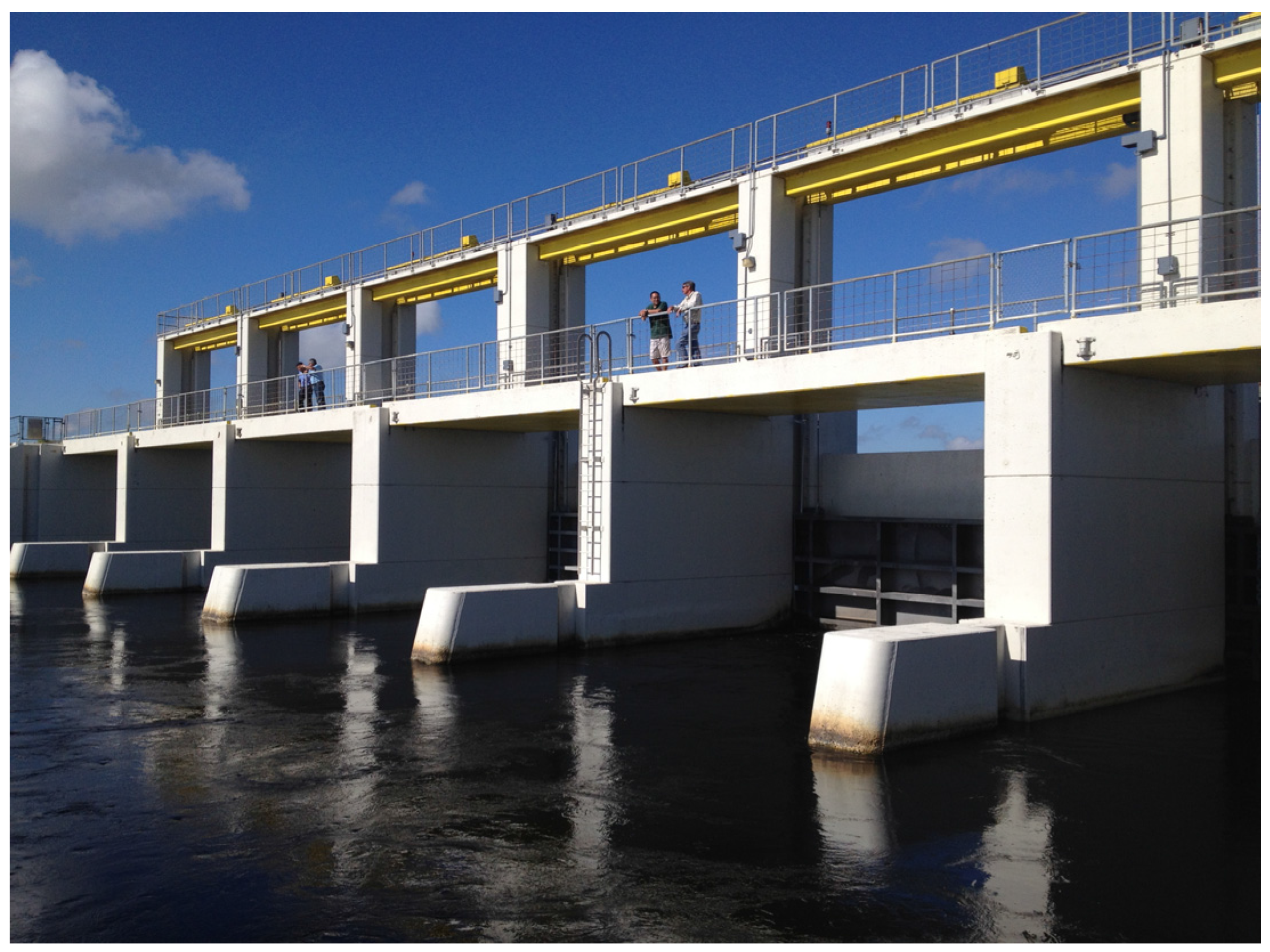
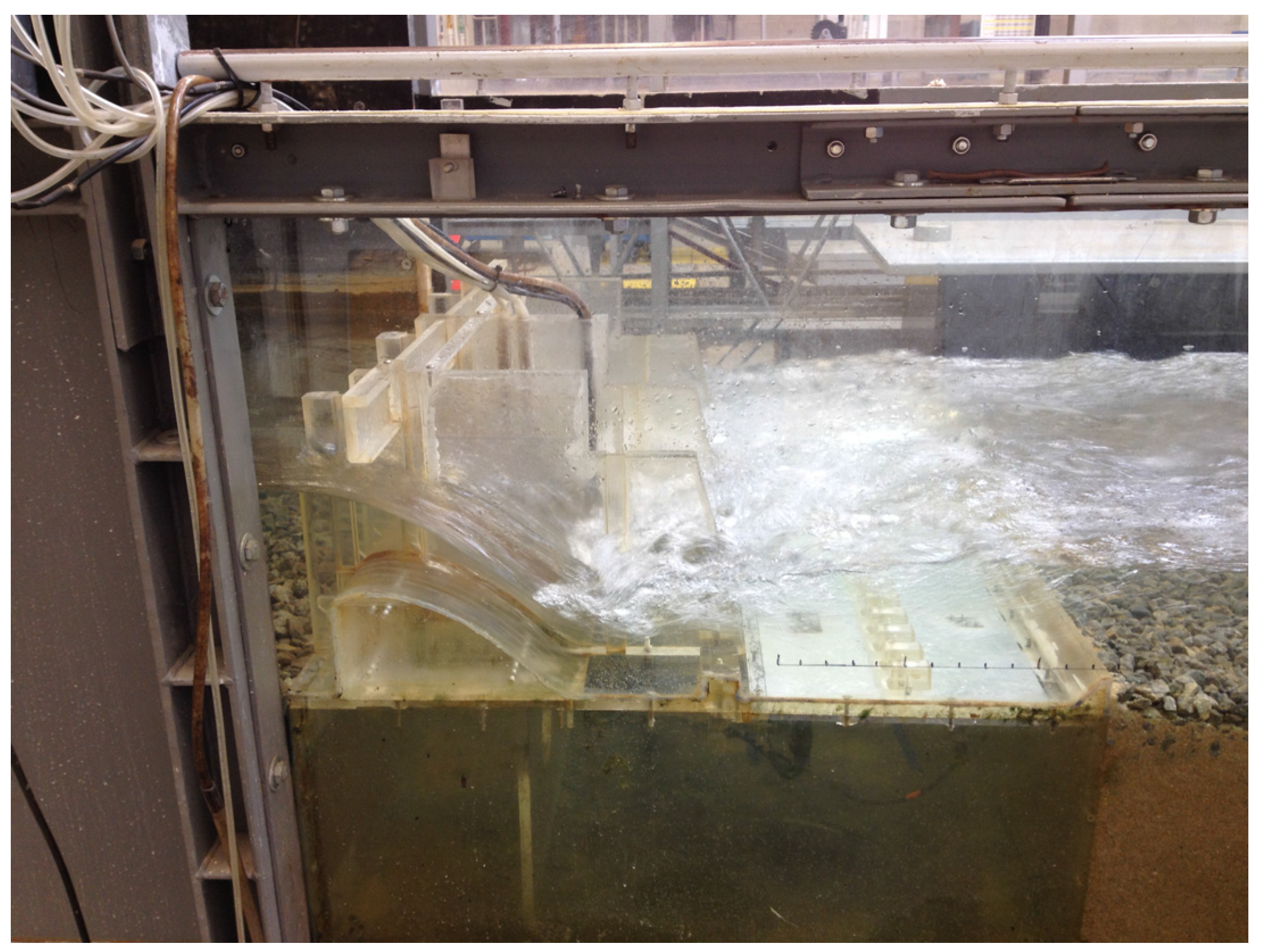
The particular spillway modeled in the laboratory at the Georgia Institute of Technology is Structure S65E on the Kissimmee River in central Florida immediately upstream of Lake Okeechobee (Figure 1). The structure is a low-head ogee spillway with vertical gates and is operated by the South Florida Water Management District (SFWMD) which has responsibility for utilizing and protecting the water resources for nearly 8 million residents from Orlando to Miami to the Everglades. A large number of these low-head spillway structures have been built as part of this water resources system to control flooding, direct water to agricultural areas, divert water to storm-water treatment areas and then to the Everglades, and supply water to the Miami metropolitan area. While the Kissimmee River south of Orlando, Florida is being restored to its natural condition by removing some spillway structures and reconnecting the floodplain and main channel in order to improve aquatic habitat and flood water storage, Structure S65E will remain in place to accomplish its flood control purpose and to help manage the aquatic ecosystem. A 1:30 scale hydraulic model of this structure has been constructed (Figure 2) and tested in the Georgia Tech Hydraulics Laboratory with the objectives of improving the accuracy of head-discharge relationships measured at the structure and examining the threat to stability of the structure due to scour of the downstream canal sediment bed during droughts and accompanying low tailwater levels in Lake Okeechobee. In addition, the structure is often operated under submerged flow conditions, and so it is of interest to know the relative impact of tail-water elevation on scour or deposition. Within this context, the influence of a protected apron of varying lengths on downstream scour is also explored.
Considerable research has been conducted on the flow field downstream of a sluice gate for which the tailwater submerges the hydraulic jump induced by a supercritical jet issuing from under the gate. Dey and Sarkar [1] showed from their measurements that the flow pattern immediately downstream of the sluice gate over the top of a solid apron of varying roughness was one of jet development as its vertical thickness increased and the maximum horizontal velocity decreased in the downstream direction. The jet development layer was overlain by a reverse flow and circulation back toward the gate. Increasing bed roughness increased the bed shear stress and its rate of decay in the flow direction. Habibzadeh et al. [2,3] studied experimentally the effect of baffle blocks on a submerged hydraulic jump downstream of a sluice gate. They classified the flow as an upwardly deflected surface jet (DSJ) upstream of the blocks or a re-attaching wall jet (RWJ) downstream of the blocks as determined by the relative influence of the upstream Froude number of the supercritical jet, block geometry and location, and degree of submergence of the hydraulic jump.
Figure 1. Prototype Spillway Structure S65E.
Water 07 05378 g001
Figure 2. Spillway Model (1:30 scale).
Water 07 05378 g002
Measurements of the flow field above a scour hole downstream of a submerged jet discharging from a sluice gate onto a solid apron at various stages of development by Dey and Sarkar [4] showed that the decay rate of maximum local Reynolds stress was slower over the scoured bed than the apron. Guan et al. [5] concluded from flow-field measurements in the scour hole downstream of a submerged weir that a recirculation zone occurred above the upstream slope of the hole, and that turbulence structures in this region contributed to its size.
In addition to submergence of the hydraulic jump downstream of a weir or spillway, the structure itself can be submerged for tailwater levels greater than its modular limit; that is, at the modular limit a small increase in tailwater elevation increases the upstream head and thus alters the head-discharge relationship. Several studies have been conducted on identifying the modular limit and predicting modification of the free-flow discharge coefficient for the submerged case [6,7,8,9,10]; however, the effect on scour downstream of the structure is not as well known. Wu and Rajaratnam [10] classified the flow types for a submerged rectangular weir in order of increasing degree of submergence as: (1) impinging (or diving) jet; (2) breaking wave (or surface jump); (3) surface wave; and (4) surface jet. The latter three types all involved a clockwise recirculation zone below the surface flow (left to right) which may affect downstream scour.
Scour data for a two-dimensional jet flow issuing from a sluice gate (submerged and unsubmerged) from various sources have been compiled and reported by Melville and Lim [11]. They proposed a relationship for maximum scour depth based on this data set which is given by:
d s y j = 3 F j K D K y t K σ K L
in which ds = scour depth, yj = thickness of the jet at the vena contracta, Fj = jet Froude number = Vj/(gyj)1/2, Vj = jet velocity; KD = correction factor for sediment size as a function of d50/yj, with d50 = median sediment size; Kyt = correction factor for effect of tailwater submergence as a function of yt/yj where yt = downstream tailwater depth, Kσ = effect of nonuniform grain size distribution dependent on the geometric standard deviation of the distribution, and KL accounts for the apron length, Lt, downstream of the sluice gate in terms of Lt/yj. Equation (1) defines an envelope curve for maximum scour depth utilizing several different data sources. The correction factor for submergence, however, is unproven and requires more data points according to the authors.
Dargahi [12] conducted experiments on scour downstream of the U.S. Army Corps of Engineers (USACE) standard ogee spillway profile with a protective plate of constant length serving as an apron. In one set of experiments, the plate was smooth and in another set, two rows of blocks in the form of hexagon nuts were attached to the plate. In addition to plate roughness, the experimental variables were the discharge per unit width, q, and the sediment size of the mobile bed, d50. Complex three-dimensional flow patterns with large-scale unsteadiness developed downstream of the plate due to the hydraulic jump located there. In the vertical plane, a clockwise circulation developed below the jump which created the upstream portion of the scour cavity while the downstream portion was characterized by sediment being transported out of the scour cavity in the streamwise direction. Vortices in the horizontal plane generated two scour holes in the cross-stream direction due to secondary circulation just upstream of a third scour hole at the flume centerline. Maximum scour depth at the flume centerline was found to be described by the following best-fit regression equation:
d s H = 1.7 ( H d 50 ) 0.222
in which H is the upstream head relative to the spillway crest. In Dargahi’s experiments, H/d50 varied between 8 and 200.
Oliveto [13] carried out experiments on the time development and depth of scour downstream of an ogee spillway with a horizontal apron on which a hydraulic jump was located. The experimental variables were d50, discharge per unit width, q, distance from the toe of the jump to the end of the solid apron, Lt, and tailwater depth relative to the floor of the apron, yt. Dimensional analysis and regression of the data according to the proposed dimensionless variables produced:
d s t y t = 0.16 F d 1.68 ( L t y t ) 0.49 ( y t d 50 ) 0.22 σ 1.41 T 0.19
in which dst = maximum scour depth at time t, Fd = densimetric grain Froude number defined as V / ( g d 50 ) 1 / 2 , V = q/yt, g′ = reduced gravitational acceleration = (SG − 1)g with SG = specific gravity of sediment, σ = geometric standard deviation of the sediment size distribution, and T = ( g d 50 ) 1 / 2 t / y t with t = time from beginning of experiment. Equation (3) is restricted to the limits: 2.4 × 10³T ≤ 1.4 × 10⁶, 1.30 ≤ Fd ≤ 2.87, and 1.2 ≤ Lt/yt ≤ 11.0.
This paper focuses on the influence of spillway submergence and length of a riprap apron in controlled and free flows on the maximum scour depth and its location downstream of an ogee spillway in the SFWMD, but the results are presented such that they may be of general interest. Although some preliminary data on this subject have been reported previously [14,15], the present paper includes additional scour data and presents a more comprehensive analysis of the results and their connection to the flow fields initiating scour relative to apron length and degree of submergence of the structure.

2. Materials and Methods

2.1. Model Spillway

A fixed-bed, sectional model of the S65E spillway and tailrace on the Kissimmee River was constructed at a 1:30 undistorted geometric scale in the Georgia Tech Hydraulics Laboratory using Froude number similarity. At the chosen scale of 1:30, the model Reynolds number based on spillway head was of the order of 105, which ensured a turbulent flow regime as in the prototype [16]. The model Weber number was estimated to be of the order of 103 which allowed surface tension effects to be neglected. Flow depths in the model were greater than 20 mm, which is another criterion for avoiding surface tension effects manifested by capillary waves in free-surface flow models [16]. Furthermore, the spillway crest and the floor of the stilling basin were constructed of acrylic which minimized roughness effects in the spillway model even though they were already small because of the relatively small spillway crest height.
The USACE standard ogee spillway model with vertical gates included the two central bays plus half a bay on either side to represent approximately one-half the prototype spillway width. The actual crest length of the model spillway was 0.81 m (24.3 m), or 49% of the total crest length of 1.65 m (49.5 m). (Model dimensions are followed by prototype dimensions in parentheses in this section of the paper.) This arrangement allowed the central pier of the spillway to be aligned with the centerline of the flume and marginalized flume wall effects while reproducing realistic prototype gate settings and hydraulic jump behavior in the central region of the stilling basin and tailrace. The ogee spillway crest, vertical gates, breast wall, gate stops, gate slots, stilling basin, and impact blocks were fabricated with undistorted geometric similarity using clear acrylic materials as shown previously in Figure 2 to minimize model roughness. The streamwise extent of the model was from a point 1.53 m (46 m) upstream of the spillway crest to a point in the tailrace 7 m (210 m) downstream of the spillway crest. These lengths provided for adequate flow development upstream and noninterference of the flume tailgate with the scoured region downstream of the spillway.
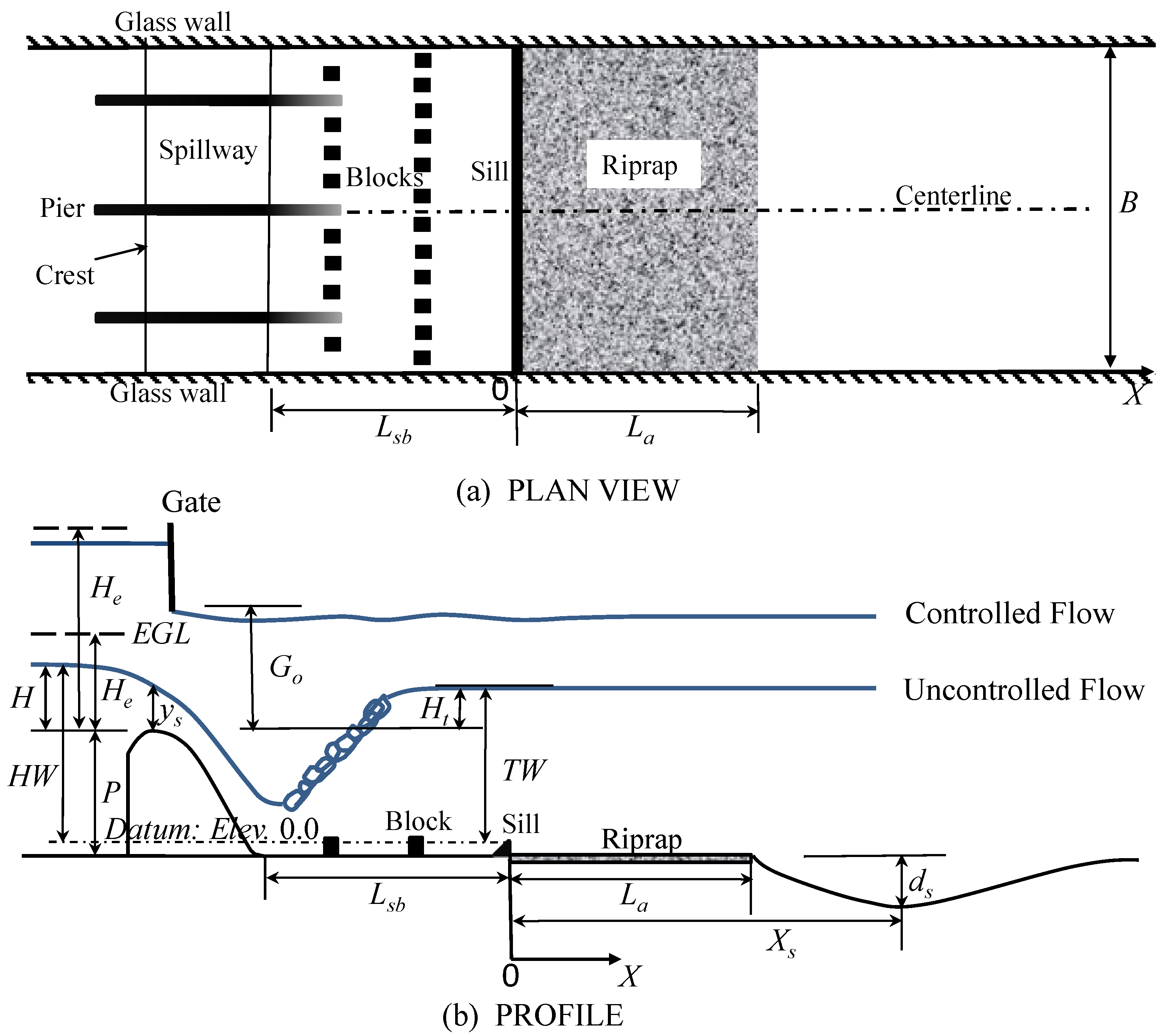
The spillway profile was a standard ogee crest as shown in Figure 3 with a height, P = 0.115 m (3.44 m), and a design head, Hd = 0.147 m (4.42 m). Headwater and tailwater elevations, HW and TW, respectively, were measured with respect to a standard SFWMD datum located 0.016 m (0.49 m) above the stilling basin floor in order to maintain consistency with historical records on tailwater elevations. Heads are all measured relative to the spillway crest and are unaffected by the choice of tailwater and headwater elevation datum. The stilling basin included two rows of impact blocks and an end sill all with a height of 0.026 m (0.79 m). The length of the stilling basin, Lsb was 0.54 m (16.2 m).
Figure 3. Spillway Definition Sketch (Not to Scale). (B = 0.91 m (27.3 m); P = 0.115 m (3.44 m); Lsb = 0.54 m (16.2 m)).
Water 07 05378 g003
In this study, in contrast to the original structure design which had a pre-formed plunge pool downstream of a very short riprap apron that experienced considerable erosion, a riprap apron with a length of La was installed downstream of the stilling basin such that La/Lsb = 1.0 and 2.0. No plunge pool was excavated in the model downstream of the riprap apron. The model riprap was sized according to Shields’ criterion for fully-rough turbulent flow such that the critical shear stress ratio was equal to the sediment diameter ratio which can be shown to be equal to the geometric scale ratio for a Froude number model. Accordingly, the prototype riprap apron diameter was modeled with angular, crushed granite having d50 = 1.5 cm (0.46 m) and a geometric standard deviation of 1.3. The first 0.1 m (3.0 m) of the riprap apron was cemented in the model using polyurethane to prevent unraveling there in close proximity to the end sill. The remainder of the riprap apron was mobile and placed to a thickness of twice the median grain size. The mobile sand bed downstream of the apron had d50 = 1.1 mm in the model and a geometric standard deviation of 1.3. The Kissimmee River sediment is fine sand with as much as 25% organic content in bed load during low flows [17].

2.2. Experimental Measurements

Scour experiments were conducted for five spillway test conditions at the design discharge per unit crest length of 0.0838 m2/s (13.77 m2/s) with two riprap apron lengths of La/Lsb = 1.0 and 2.0. For gated operating conditions, the gate opening was 0.0846 m (2.54 m). Tailwater elevation was varied to produce both submerged and unsubmerged flow conditions as determined by established spillway operating ranges. The gate opening was set by lowering the gates until they made a snug fit with an acrylic block that had been precision machined to the correct height relative to the spillway crest. The acrylic block was then carefully removed from under the gate without changing its position. The gates were held in place by friction between rubber gate gaskets and the gate slots, and no vibration effects were observed. For each test condition, the discharge was gradually increased to the design value with the tailgate raised to obtain saturation of the initial sand bed, and then the tailgate was adjusted to the target tailwater elevation at which time scour commenced. Scour depths were measured every few hours until the equilibrium condition, defined as less than a 5% change in scour depth in 24 h, was reached which required four to five days.
Headwater elevation was measured with a needle gauge and a piezometer, while tailwater elevation and water surface profiles were measured with a point gauge and a capacitance wave gauge to capture water surface fluctuations. Headwater elevations were measured 1.02 m (30.5) m upstream of the spillway crest, while tailwater elevations were taken at a distance of 3.05 m (91.4) m downstream of the crest as in the prototype. The water surface profile was measured in increments of 0.15 m (4.5 m) in the stream-wise direction for regions of gradually-varied flow, while measurements were taken every 0.06 m (1.8 m) where the flow was rapidly-varied. Discharge was measured by an electromagnetic flow meter with an uncertainty of ± 3 × 10⁻⁴ m3/s (1.5 m3/s).
Velocity and turbulence quantities were measured for a fixed bed corresponding to the initial bed configuration before scour using a Son-Tek (San Diego, CA, USA) 16 MHz MicroADV (acoustic Doppler velocimeter). The cylindrical measuring volume of the ADV had a height of 0.45 cm and a diameter of 0.40 cm. Sampling rates from 25 to 50 Hz were selected based on the guideline suggested by Garcia et al. [18]. A sampling duration of five minutes was determined to be adequate to obtain constant time-averaged quantities based on long-duration ADV signal records measured downstream of the spillway. Filtering of the ADV signal was accomplished by requiring a minimum value of the correlation coefficient, which measures the relative effect of noise on signal phase coherency, to be 70%. The signal-to-noise ratio was required to be greater than 15 before a time record was accepted as recommended by the manufacturer for measuring turbulence, and the phase-space threshold despiking algorithm [19] was applied to remove any spikes in the signal record. The percentage of remaining data records after the filtering process was approximately 80%; despiking removed less than 1% of the data. Collection of high quality data was aided by using a dilute kaolin slurry as seeding particles. Velocity spectra were checked to ensure no bias due to Doppler noise. With similar quality-control protocols, an ADV has been used successfully to measure turbulence quantities in several other relevant investigations including flow fields downstream of submerged jets on solid aprons before and after scouring [4], and in a scour hole downstream of a submerged weir [5], for example.
Approximately 10 to 15 points were sampled with the ADV in each of a series of vertical profiles taken along the flume centerline at a stream-wise spacing that varied from 0.1 to 0.4 m (3 to 12 m). For the submerged flow cases, velocity and turbulence profiles were measured both in the stilling basin and above the riprap apron and mobile bed area, while for free-flow cases with the hydraulic jump held in the basin, measurements were made only downstream of the stilling basin to avoid regions of flow separation and air entrainment in the jump.

3. Results and Discussion

3.1. Maximum Scour Depth and Location

The scour depth results for spillway operating conditions tested are shown in Table 1 in prototype units. (In this and succeeding sections, results are given in prototype units unless otherwise noted or in dimensionless form.) The flow types are categorized as uncontrolled submerged (US), uncontrolled free (UF), controlled submerged (CS), controlled free (CF), and uncontrolled jet (UJ). Submerged flow refers to cases for which the modular limit of the spillway was exceeded in contrast to free flows for which there was no tailwater influence on the discharge, while controlled vs. uncontrolled modifiers signify orifice flow under vertical gates as opposed to gates fully open with weir flow over the spillway. All experimental runs are reported in Table 1 for the spillway design discharge, Qd, of 680 m3/s and a gate opening height, Go, of 2.54 m for controlled flow. Run 1 applied the maximum allowable tailwater condition, while Run 2 tailwater corresponded to the hydraulic jump occurring in the stilling basin with the toe of the jump at the base of the spillway consistent with the stilling basin design. In Run 3, tailwater was at its maximum allowable elevation and the gate opening was set so that the maximum allowable headwater elevation also occurred. Run 4 had the same tailwater elevation as Run 2 with a free hydraulic jump but with orifice flow under the gates rather than weir flow with the gates fully open. Finally, the uncontrolled jet case in Run 5 was for a low tailwater elevation that caused the hydraulic jump to be swept to the end sill of the basin resulting in a jet coming off the sill. Runs 6 through 10 paired up with Runs 1 through 5, respectively, but with the longer riprap apron of La/Lsb = 2.0. All variables in the table were previously defined in Figure 3.
Table 1. Experimental conditions and results in prototype units. (Qd = 680 m3/s, Go = 2.54 m).
RunFlow TypeLa/LsbHW (m)TW (m)He (m)Ht (m)ds (m)Xs (m)
1US1.06.965.794.082.832.6433.5
2UF1.06.433.963.561.004.7651.3
3CS1.07.606.004.713.042.9433.5
4CF1.07.023.974.151.015.1753.9
5UJ1.06.323.213.450.255.4275.3
6US2.07.065.844.182.881.6446.3
7UF2.06.453.873.580.914.3168.6
8CS2.07.676.034.793.071.9448.1
9CF2.07.003.884.140.924.8070.1
10UJ2.06.353.183.480.225.6079.5
As discussed previously, the model scale was chosen to minimize Reynolds number and Weber number effects. Furthermore, the spillway design variables of upstream head to design head ratio (He/Hd), spillway height ratio (P/He), and upstream head to gate opening height ratio (He/Go) were varied within narrow ranges for the various design operating conditions in Table 1. In addition, the stilling basin length (Lsb) was fixed at the design value for a standard ogee spillway so that variability of the ratio He/Lsb was small. With these study specifications, in which the primary independent variables of interest were the effects of riprap apron length and tailwater submergence on downstream scour, the results of a dimensional analysis for maximum scour depth, ds, can be presented as:
d s Δ Z = f 1 ( H t H e , L a L s b , H e d 50 )
in which ΔZ = height of the headwater relative to the stilling basin floor, Ht = tailwater head relative to the spillway crest, He = total energy head upstream of the spillway relative to the crest, La = length of riprap apron and d50 = median grain size of the mobile bed (Figure 3). Proceeding in a similar fashion for the distance from the stilling basin end sill to the location of maximum scour depth, Xs, the dimensional analysis yields
X s L s b = f 2 ( H t H e , L a L s b , H e d 50 )
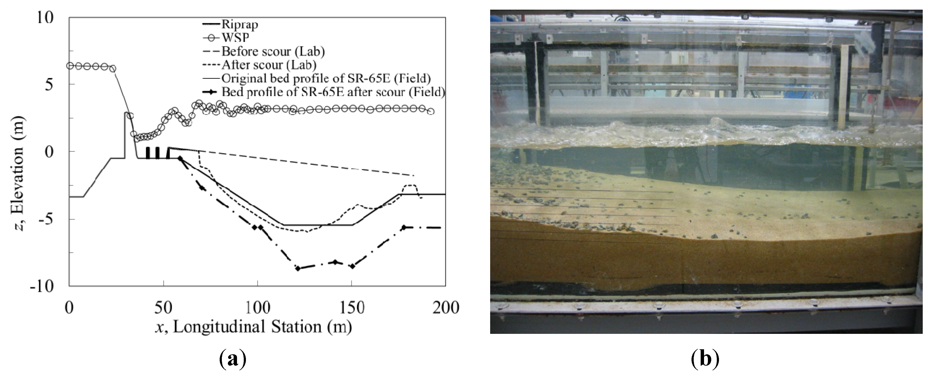
The effect of model sediment size is reflected in the variables KD in Equation (1), He/d50 in Equations (2), (4) and (5), and yt/d50 in Equation (3), and it is difficult to predict without testing a range of sediment sizes or by determining the critical velocity for initiation of motion of the sediment in the field. The latter approach is especially challenging in the present case for which organic matter in the sediment can introduce interparticle forces that affect its resistance to scour. However, a comparison of the original plunge pool design with the size and geometry of the scour hole from this study is shown in Figure 4 for the UJ case (Run 5 in Table 1) which corresponds to the lower expected design limit for tailwater elevation. In this case, the lab data match very well the original plunge pool profile determined from a previous model study [20]. The additional plunge pool scour shown in Figure 4 during the drought of 2007 and 2008 is based on a field bathymetric survey provided by SFWMD [21]. The observed field scour profile is consistent with the tailwater elevation, as determined by the water level in Lake Okeechobee, falling below the expected minimum operating level and causing hydraulic jump sweepout as suggested by the USACE MAGO (maximum allowable gate opening) curves [21].
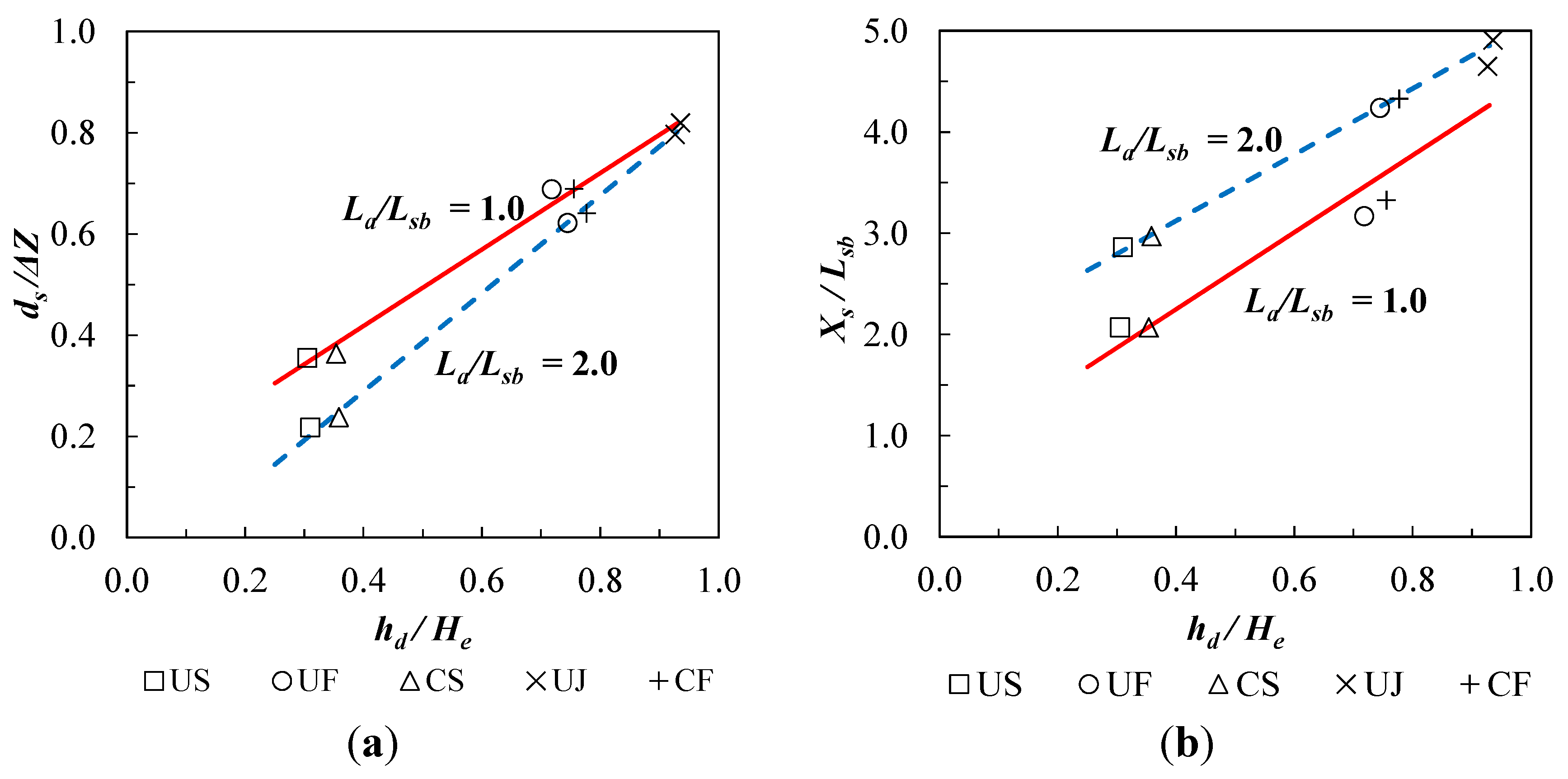
Although the validation of model sediment size shown in Figure 4 is somewhat limited, measured values of ds/ΔZ and Xs/Lsb are presented in Figure 5 as a function only of the first two dimensionless ratios on the right hand sides of Equations (6) and (7) which are a measure of the effects of tailwater submergence and riprap apron length on downstream maximum scour depth and location, respectively. The horizontal axis is modified slightly to become hd/He = (1.0 – Ht/He) to provide additional generality. With this definition, hd becomes the difference between upstream energy grade line elevation and tailwater elevation such that scour depth would be expected to increase with increasing values of hd.
Figure 4. (a) Comparison of experimental centerline scour profile for Run 5 with stilling pool design and historic scour due to low tailwater; (b) Equilibrium scour profile photo for Run 5.
Water 07 05378 g004
Figure 5. (a) Maximum scour depth for riprap apron lengths of La/Lsb = 1.0 and 2.0; (b) Location of maximum scour depth relative to stilling basin end sill for La/Lsb = 1.0 and 2.0.
Water 07 05378 g005
For each apron length, maximum scour depth ds and its distance downstream of the stilling basin end sill Xs both increased with increasing differential head hd associated with decreasing tailwater elevation as shown in Figure 5. For a given apron length, ds and Xs were relatively insensitive to the flow being controlled or uncontrolled; instead, the degree of submergence relative to submerged, free, or jet flow classifications was paramount in determining maximum scour depth and location. In general, the increased apron length reduced ds and increased Xs except for the UJ flow case for which there was relatively little influence of apron length. Doubling the apron length reduced ds by approximately 38% and 34% for US and CS flows, respectively, while it was reduced by approximately 9% and 7% for UF and CF flows, respectively. The values of Xs increased by about 40% for US and CS flows and about 30% for UF and CF flows. These results show that increasing the riprap apron length effectively reduced maximum scour depth and moved it further downstream in both submerged and free flows but not for UJ flow on which its influence was minor.
For the UF and CF flows, the free hydraulic jump in the stilling basin was effective in energy dissipation but scour still occurred. Submergence of both the jump and the spillway itself in US and CS flows reduced scour compared to CF and UF flows partly due to smaller mean flow velocities downstream of the stilling basin. In the UJ jet flow case, sweeping out of the hydraulic jump caused severe disturbance in the water surface profile downstream of the stilling basin [15] and the largest scour depth. Although the longer riprap apron with greater surface roughness lengthened the zone of water surface disturbance, the maximum scour depth and its location were virtually the same as for the shorter apron.

3.2. Flow Fields

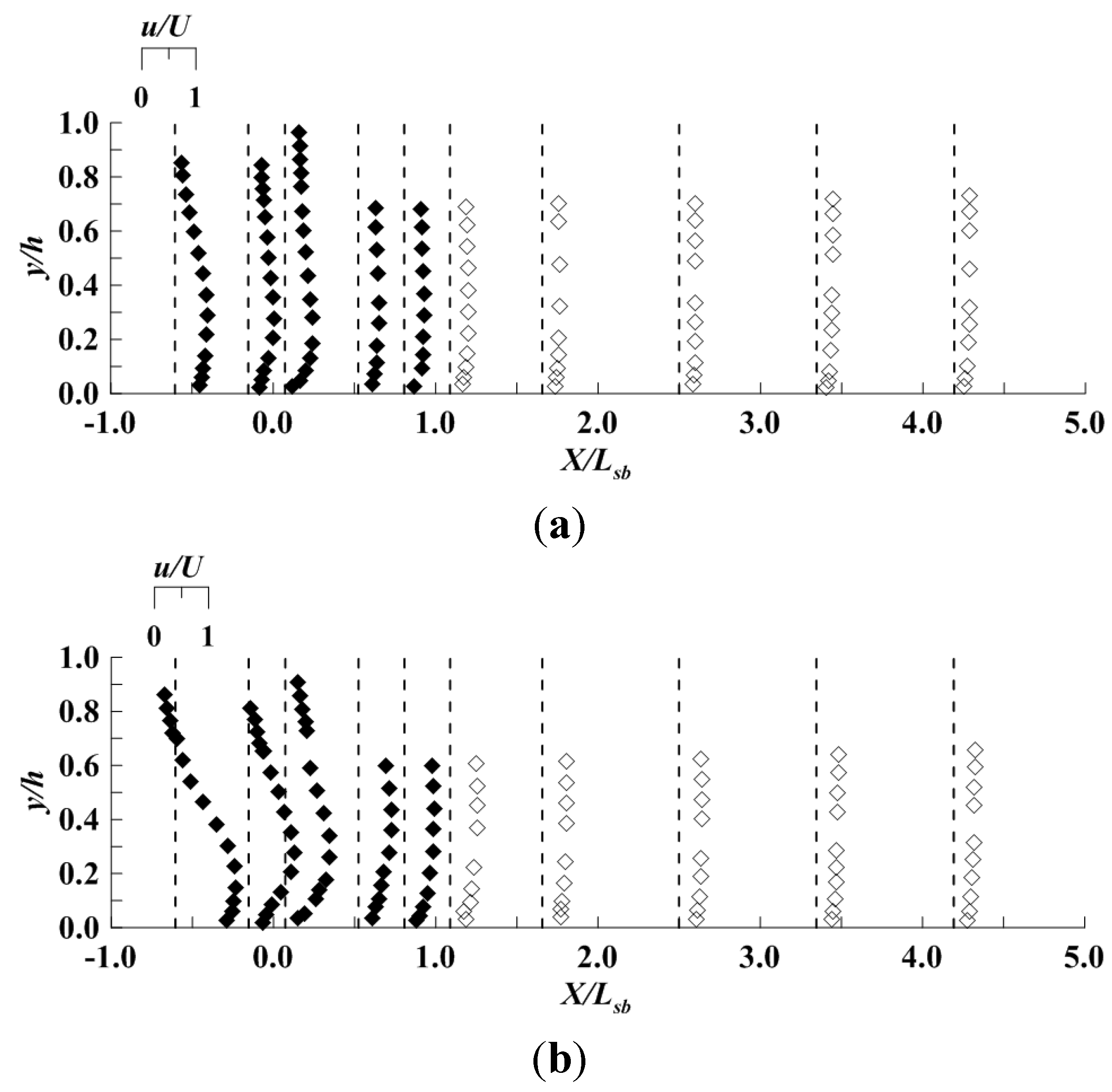
Velocity profiles for submerged flow, both uncontrolled and controlled, are shown in Figure 6 prior to scour. The streamwise point velocities are nondimensionalized by a reference bulk velocity, U, at the location of the spillway crest, while the vertical coordinate y is nondimensionalized by the local depth, h, which is determined by the water surface and bed profiles. A prominent bulge occurred in the CS flow velocity profile in Figure 6b at y/h ≈ 0.2 within the stilling basin due to plunging of the submerged jet and an overlying reverse flow circulation; however, the bulge of excess velocity mixed upward within the stilling basin and over the riprap apron rapidly such that a monotonic increase in streamwise velocity with distance above the bed occurred at the exit from the riprap apron (X/Lsb = 1.0) and was maintained over the scour zone. For the US flow in Figure 6a, the velocity bulge was at a slightly higher elevation and less pronounced; however, flow visualization showed a reverse circulation in the upper part of the flow in the stilling basin as for CS flow but in a thinner layer near the free surface. Taking into account the difference in reference velocities for the CS flow vs. the US flow, the velocity profiles downstream of the riprap apron had a similar shape and magnitude near the bed consistent with maximum scour depths that were nearly the same for these two submerged flow cases.
For comparison with the submerged flow velocity profiles in Figure 6, unsubmerged or free flow profiles can be seen in Figure 7. Because of entrained air and flow separation within the stilling basin due to the hydraulic jump, only velocity profiles after the jump are shown downstream of the stilling basin where the flow had reattached and air bubbles had dissipated. Velocity profile shapes and maximum velocities near the bed are similar for the UF and CF flows in Figure 7 which accounts for similar maximum scour depths for these two unsubmerged flow cases. The combination of the blocks and end sill in the stilling basin, and the flow over the riprap apron, resulted in significant energy dissipation and vertical mixing of the nonuniform velocity profile within the jump itself. However, scour depths were significantly larger for the free flow cases in Figure 7 than for submerged flows shown in Figure 6 primarily because of lower tailwater elevations and higher velocities in the free flows near the bed.
Figure 6. Vertical velocity profiles of non-dimensional values of u in submerged flow for La/Lsb = 1.0: (a) Run 1 (US; Umodel = 1.40 m/s) and (b) Run 3 (CS; Umodel = 1.03 m/s). (Closed symbols above stilling basin floor and riprap apron; open symbols for scour region).
Water 07 05378 g006
An examination of near-bed velocities for the longer riprap apron at y/h = 0.10, which was the vertical location where maximum turbulent kinetic energy was found, revealed that they had nearly the same magnitude at X/Lsb = 2.5 just downstream of the end of the apron as at the corresponding downstream distance for the shorter apron for both submerged and free flows. Defining the bed velocity as the streamwise velocity ub at y/h = 0.10, and nondimensionalizing it by the critical shear velocity u*c, values of ub /u*c were approximately 14.5 for US and CS flows at X/Lsb = 1.1 and 2.5 regardless of the apron length. Similarly, values of ub/u*c for UF and CF flows were approximately 18.0 at X/Lsb = 1.1 and 2.5 for both apron lengths. Hence, the values of streamwise velocities near the bed are consistent with observed larger scour depths for free flow as opposed to submerged flow, but they do not seem to explain the observed smaller maximum scour depths for the longer riprap apron.
Figure 7. Vertical velocity profiles of non-dimensional values of u in unsubmerged flow for La/Lsb = 1.0: (a) Run 2 (UF; Umodel = 1.35 m/s) and (b) Run 4 (CF; Umodel = 1.03 m/s). (Closed symbols above stilling basin floor and riprap apron; open symbols for scour region).
Water 07 05378 g007
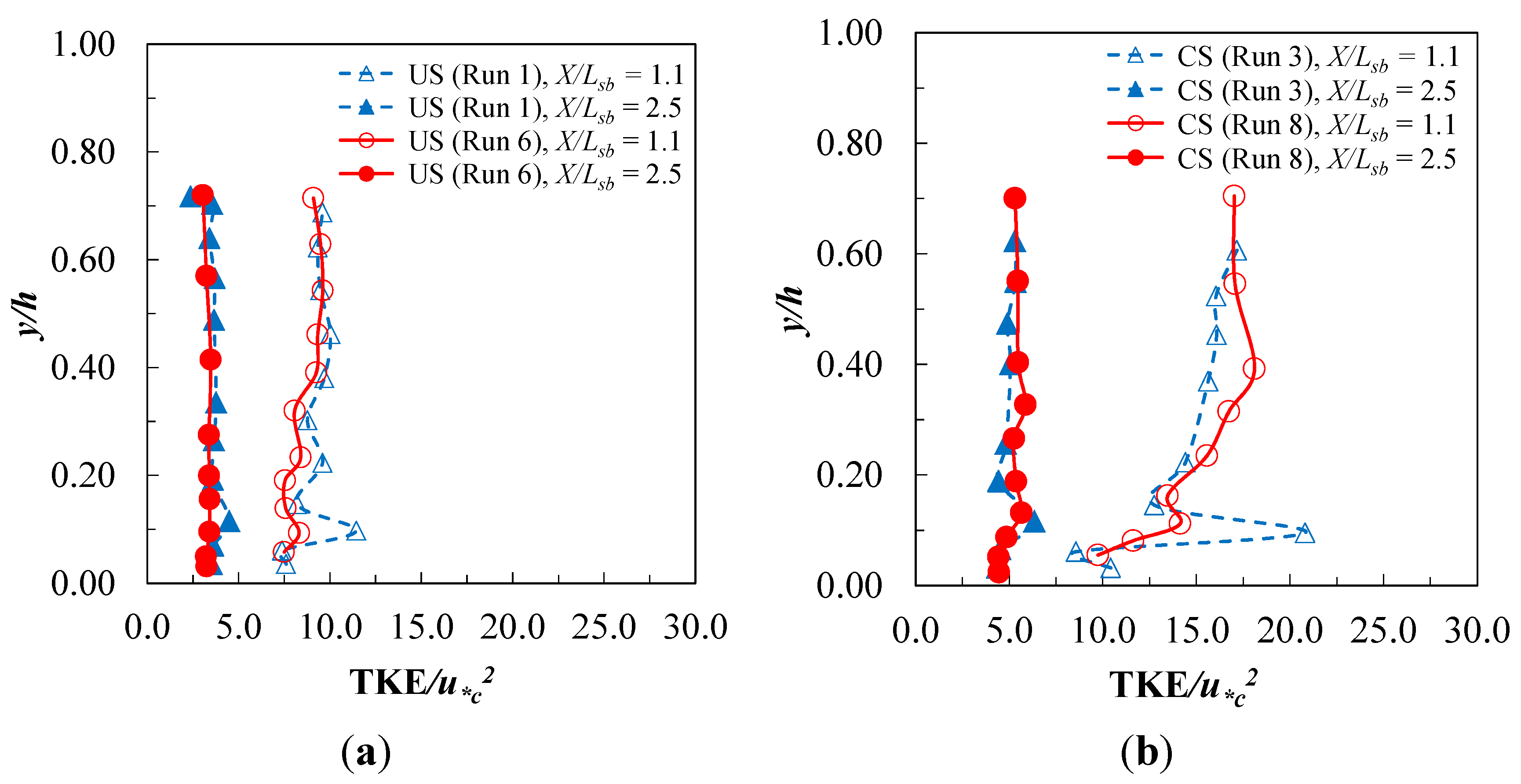
In order to further study the effect of riprap apron length on maximum scour depth, vertical profiles of turbulent kinetic energy (TKE) prior to scour were measured along the length of the stilling basin and downstream scour area where TKE = 0.5 ( < u 2 > + < v 2 > + < w 2 > ) , and the symbols < > refer to a time average of the enclosed component of turbulent velocity fluctuation squared. Profiles for CS and US flows are shown in Figure 8 at two stations, X/Lsb = 1.1 and 2.5, each just downstream of the end of the short and long riprap aprons, respectively. The profiles show a relatively constant value of TKE over much of the depth, except for a maximum value near the bed, and there is general diminishment in TKE over the full depth in the streamwise direction. Reverse circulation in the upper portion of the stilling basin created a shear zone that likely contributed to elevated TKE that persisted into the scour zone albeit at a diminishing rate as the jet flow profile recovered. Although not showing TKE profiles, Dey and Sarkar [4] presented similar profile shapes for longitudinal and vertical turbulence intensities downstream of a sluice gate from which a submerged wall jet issued onto a solid apron.
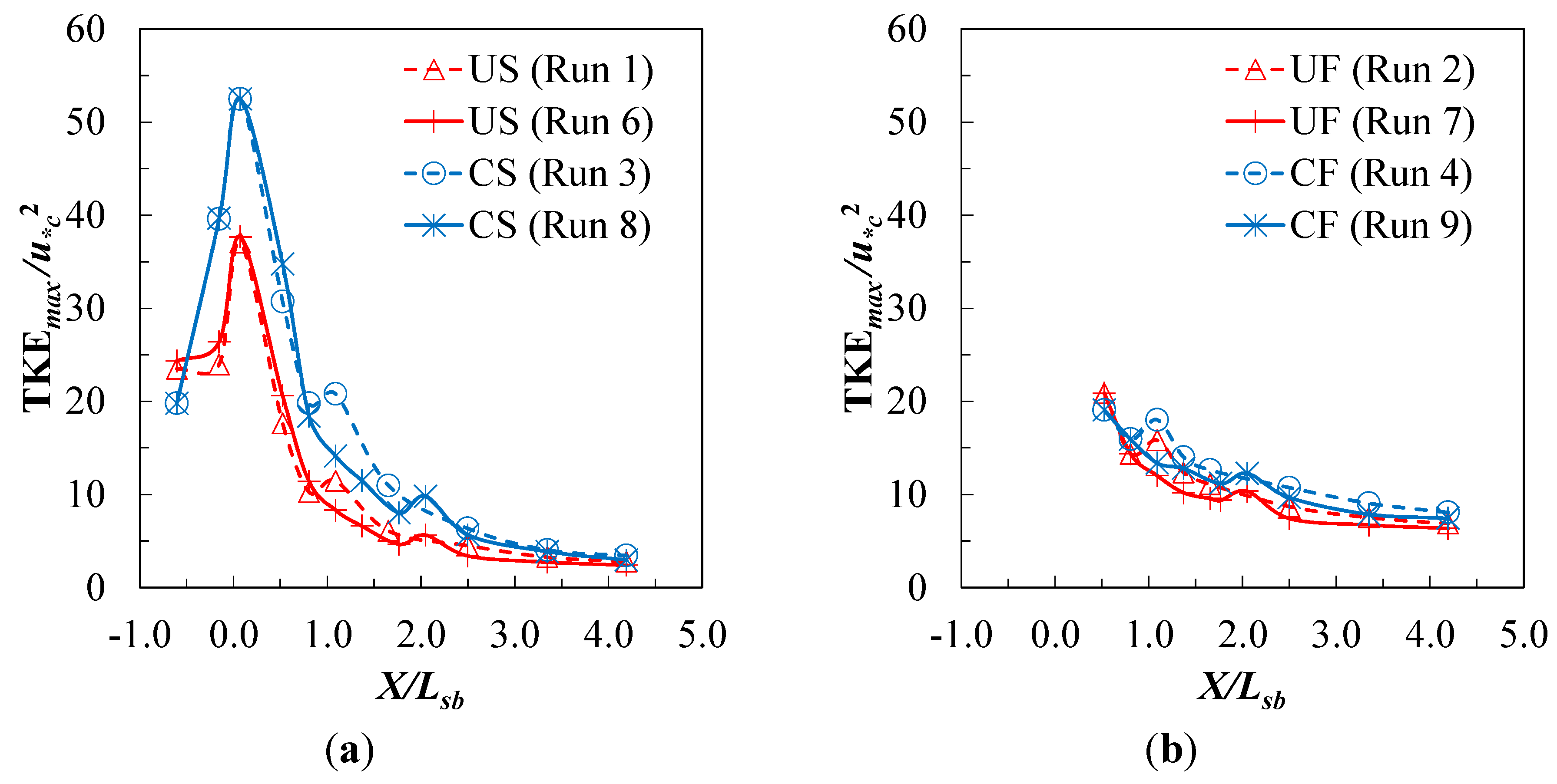
The value of TKEmax near the bed was determined for each measured vertical profile, and downstream of the stilling basin it was found to occur at a relative depth of y/h ≈ 0.10 for both submerged and free flows regardless of the riprap apron length. Biron et al. [22] suggested that the maximum TKE in a vertical profile, which occurred in their experiments of flow around lateral deflectors at y/h ≈ 0.10, was the best indicator of bed shear stress when multiplied by a constant factor of 0.19. In an experimental study of scour around bridge abutments, Hong et al. [23] showed that elevated values of TKE near the bed prior to scour were coincident with maximum local scour depths caused by flow separation and accompanying turbulent eddies as the flow was blocked and diverted around the abutment.
Streamwise profiles of TKEmax for submerged and free flows are shown in Figure 9. For the submerged flows in this study, the largest value of TKEmax occurred just downstream of the end sill of the stilling basin (X/Lsb = 0.073) as shown in Figure 9a. At this location, TKEmax/u*c2 for CS flow was 53 while it was 37 for US flow. The difference in these maximum values may be attributable to flow separation and turbulence production near the bed due to the plunging jet in CS flows and its impact with the end sill. Downstream of the largest near-bed TKE values, rapid decay of TKE occurred due to turbulent energy dissipation such that less difference in TKE existed between CS and US flows in the downstream direction. Bed roughness contribution to the TKE distribution can be observed as a slight local rise in TKE at the transition from the end of the riprap apron to the sand bed at X/Lsb = 1.0 for the short riprap apron and X/Lsb = 2.0 for the long apron. The maximum scour-depth location was X/Lsb ≈ 2.0 for the short apron where TKEmax was considerably higher than for the longer apron with maximum scour depth at X/Lsb ≈ 3.0. Thus, the greater decay of TKE for the longer riprap apron may contribute to the observed smaller scour depths for this case. What also follows from this interpretation is that further increases in riprap apron length may not be useful because TKEmax approached a constant value in the downstream direction. For UF and CF flows, the TKEmax distribution shown in Figure 9b decayed more rapidly but to a higher constant value than for submerged flows consistent with greater scour depths but still with some influence of riprap apron length due to shifting of the scour region downstream by the longer apron where TKEmax was slightly less. Although accurate measurements of TKE and velocity distributions could not be made for the UJ flow due to shallow depths and extreme free-surface fluctuations, it is possible that rapid dissipation of turbulent energy in the streamwise direction to a constant value for this case resulted in essentially no influence of riprap apron length on maximum scour depths.
Figure 8. Vertical profiles of TKE just downstream of end of riprap aprons at X/Lsb = 1.1 and 2.5 for (a) US flow and (b) CS flow.
Water 07 05378 g008
Figure 9. Streamwise distribution of maximum TKE near the bed for (a) submerged flows and (b) free flows.
Water 07 05378 g009

4. Conclusions

Changing hydrologic conditions and project objectives necessitate a re-evaluation of the stability and performance of spillway structures that are important components of a large-scale water resources system. In this paper, the results of a physical model study of an ogee spillway are reported with the objective of determining the influence of tailwater submergence and riprap apron length on maximum scour depths and their location downstream of the structure for both gate-controlled and free flows. Detailed measurements of velocity and turbulence distributions were made to provide insights into the scour results. Maximum scour depths were obtained for free flow with a swept out hydraulic jump at the lowest tailwater elevation, while increasing tailwater submergence reduced maximum scour as did a longer riprap apron. These results were explained in terms of the measured TKE and velocity distributions near the bed.
Controlled and uncontrolled submerged flows produced the least scour. Maximum scour depths were comparable for these two flow types at the same tailwater elevation and riprap apron length even though the headwater was higher for the controlled case at the same discharge. The submerged flows exhibited a complex velocity distribution within the stilling basin. Controlled submerged flow was characterized by a plunging jet and overlying recirculation. A bulge in the velocity distribution at a relative depth of about 20% gradually dissipated in the downstream direction due to vertical diffusion of momentum flux as the jet flow developed. In the uncontrolled submerged case, the velocity bulge below the water surface was at a higher elevation but with a thinner layer of reverse flow above it, and it dissipated more rapidly in the downstream direction. In spite of differences in the velocity distributions within the stilling basin for controlled and uncontrolled submerged flows, streamwise velocities near the mobile sand bed in the scour zone were nearly the same.
Controlled and uncontrolled free flows were established for an unsubmerged hydraulic jump maintained within the stilling basin at the design tailwater elevation. Velocity profile shapes and maximum velocities near the bed were similar for these two flow types as were the maximum scour depths and locations for a given riprap apron length. Significant energy dissipation and vertical mixing of the nonuniform velocity profile within the jump itself occurred in the stilling basin, but scour depths were significantly larger for these two free flow cases than for submerged flows due to lower tailwater elevations and higher velocities near the bed.
Maximum scour depths were reduced by the longer riprap apron for submerged and free flows, although more so for the former case, while apron length had no influence on scour for the lowest tailwater with the hydraulic jump swept out of the stilling basin. Upon examination of near-bed velocities at horizontal stations corresponding to positions immediately downstream of the two riprap apron lengths, they were observed to be essentially the same when comparing either free or submerged flow cases. Consideration of the streamwise distribution of maximum TKE near the bed, however, showed that after reaching its largest value at the location of the end sill due to form-induced turbulence from the stilling basin, TKEmax decayed rapidly in the streamwise direction for submerged flow cases. In this event, the longer riprap apron served to move the scour zone downstream to a location experiencing lower values of TKE which could explain the corresponding lower scour depths. The same observation was true for the two free flow cases although the overall dissipation of excess TKE was not as pronounced. The apparent asymptotic rate of decay of TKE in the streamwise direction suggests that further increases in apron length beyond twice the stilling basin length may not be useful; however, further laboratory studies are needed to confirm this observation. Measurements of TKE were not possible for the case of lowest tailwater with the jump swept out of the stilling basin, but the fact that riprap apron length had no influence on scour depth for this case could be due to the higher production of TKE at the end sill with only gradual dissipation for either apron length.
The results of this study are limited by the constant-width sectional model and two-dimensional flow so created. Gradual width expansion of the flow in the receiving channel downstream of the spillway may serve to lessen the width of the scour hole and generate secondary currents, but the essential characteristics of scour in the central region of the flow and their relationship to submergence, apron length and TKEmax are likely to be retained. Further study would be useful to confirm this supposition.

Acknowledgments

The South Florida Water Management District provided funding for construction of the spillway model but for a different set of experiments than reported herein. The Korea Institute of Civil Engineering and Building Technology funded these experiments as part of a broader study of core technologies in the field of river management conducted at the Georgia Institute of Technology. These joint contributions are gratefully acknowledged.

Author Contributions

Seungho Hong, Kwang Seok Yoon., and Terry W. Sturm conceived and designed the experiments; Celio Biering and Seungho Hong performed the experiments and analyzed the data; Kwang Seok Yoon provided background data and motivation; Juan A. Gonzalez-Castro contributed to background and field data, motivation, data analysis input, and interpretation of results; Seungho Hong and Terry W. Sturm interpreted the results and wrote the paper; and all authors participated in final review and editing of the paper.

Conflicts of Interest

The authors declare no conflict of interest.

References

  1. Dey, S.; Sarkar, A. Characteristics of turbulent flow in submerged jumps on rough beds. J. Eng. Mech. 2008, 134, 49–59. [Google Scholar] [CrossRef]
  2. Habibzadeh, A.; Loewen, M.R.; Rajaratnam, N. Performance of baffle blocks in submerged hydraulic jumps. J. Hydraul. Eng. 2012, 138, 902–908. [Google Scholar] [CrossRef]
  3. Habibzadeh, A.; Loewen, M.R.; Rajaratnam, N. Mean flow in a submerged hydraulic jump with baffle blocks. J. Eng. Mech. 2014, 140, 1–15. [Google Scholar] [CrossRef]
  4. Dey, S.; Sarkar, A. Characteristics of submerged jets in evolving scour hole downstream of an apron. J. Eng. Mech. 2008, 134, 927–936. [Google Scholar] [CrossRef]
  5. Guan, D.; Melville, B.W.; Friedrich, H. Flow patterns and turbulence structures in a scour hole downstream of a submerged weir. J. Hydraul. Eng. 2014, 140, 68–76. [Google Scholar] [CrossRef]
  6. Ansar, M.; Gonzalez-Castro, J. Submerged weir flow at prototype gated spillways. In Proceedings of World Water and Environmental Resources Congress 2003, Philadelphia, PA, USA, 23–26 June 2003.
  7. Tullis, B.P.; Neilson, J. Performance of submerged ogee-crest weir head-discharge relationships. J. Hydraul. Eng. 2008, 134, 486–491. [Google Scholar] [CrossRef]
  8. Tullis, B.P. Behavior of submerged ogee crest weir discharge coefficients. J. Irrig. Drain. Eng. 2011, 137, 677–681. [Google Scholar] [CrossRef]
  9. Azimi, A.H.; Rajaratnam, N.; Zhu, D.Z. Submerged flows over rectangular weirs of finite crest length. J. Irrig. Drain. Eng. 2014, 140, 1–12. [Google Scholar] [CrossRef]
  10. Wu, S.; Rajaratnam, N. Submerged flow regimes of rectangular sharp-crested weirs. J. Hydraul. Eng. 1996, 122, 412–414. [Google Scholar] [CrossRef]
  11. Melville, B.W.; Lim, S.-Y. Scour caused by 2D horizontal jets. J. Hydraul. Eng. 2014, 140, 149–155. [Google Scholar] [CrossRef]
  12. Dargahi, B. Scour development downstream of a spillway. J. Hydraul. Res. 2003, 41, 417–426. [Google Scholar] [CrossRef]
  13. Oliveto, G. Local scouring downstream of a spillway with an apron. Water Manag. 2013, 166, 254–261. [Google Scholar] [CrossRef]
  14. Hong, S.H.; Kim, S.J.; Sturm, T.; Stoesser, T. Effect of low tailwater during drought on scour conditions downstream of an ogee spillway. In Proceedings of River Flow, Braunschweig, Germany, 8–10 September 2010.
  15. Biering, C.; Hong, Seungho; Sturm, T.W.; Yoon, K.S.; Gonzalez-Castro, J.A. Evaluation of scour downstream of riprap aprons on low-head ogee spillways. In Proceedings of River Flow 2014, International Conference on Fluvial Hydraulics, Lausanne, Switzerland, 3–5 September 2014.
  16. Arndt, R.; Roberts, P.; Wahl, T. Hydraulic modeling: Concepts and practice. In ASCE Manual No. 97; Ettema, R., Ed.; ASCE: Reston, VA, USA, 2000. [Google Scholar]
  17. Gellis, A.C.; Pearman, J.L.; Valdes, J.J.; Habermehl, P.J. Suspended sediment and bedload monitoring of the Kissimmee River restoration, July 2007 through September 2008. In Proceedings of Joint Federal Interagency Conference 2010, Las Vegas, NV, USA, 27 June–1 July 2010.
  18. Garcia, C.M.; Cantero, M.I.; Nino, Y.; Garcia, M.H. Turbulence measurements with acoustic Doppler velocimeters. J. Hydraul. Eng. 2005, 131, 1062–1073. [Google Scholar] [CrossRef]
  19. Goring, D.G.; Nikora, V.I. Despiking acoustic Doppler velocimeter data. J. Hydraul. Eng. 2002, 128, 117–126. [Google Scholar] [CrossRef]
  20. Turner, H.O.; Pickering, G.A. Kissimmee River Structures, Central and Southern Florida Flood Control Project; US Army Engineer Waterways Experiment Station: Vicksburg, MS, USA, 1979. [Google Scholar]
  21. Gonzalez-Castro, J.A.; (SFWMD, West Palm Beach, FL, USA). Personal communication, 2012.
  22. Biron, P.M.; Robson, C.; LaPointe, M.F.; Gaskin, S.J. Comparing different methods of bed shear stress estimates in simple and complex flow fields. Earth Surf. Process. Landf. 2004, 29, 1403–1415. [Google Scholar] [CrossRef]
  23. Hong, S.H.; Sturm, T.W.; Stoesser, T. Clear-water abutment scour depth in a compound channel for extreme hydrologic events. J. Hydraul. Eng. 2015, 141, 1–12. [Google Scholar] [CrossRef]