
A Study on the Deformation Mechanism of a Landslide Reinforced with an Anti-Slip Pile Under the Effect of Reservoir Water Level Decline


Abstract
1. Introduction
2. Numerical Methodology
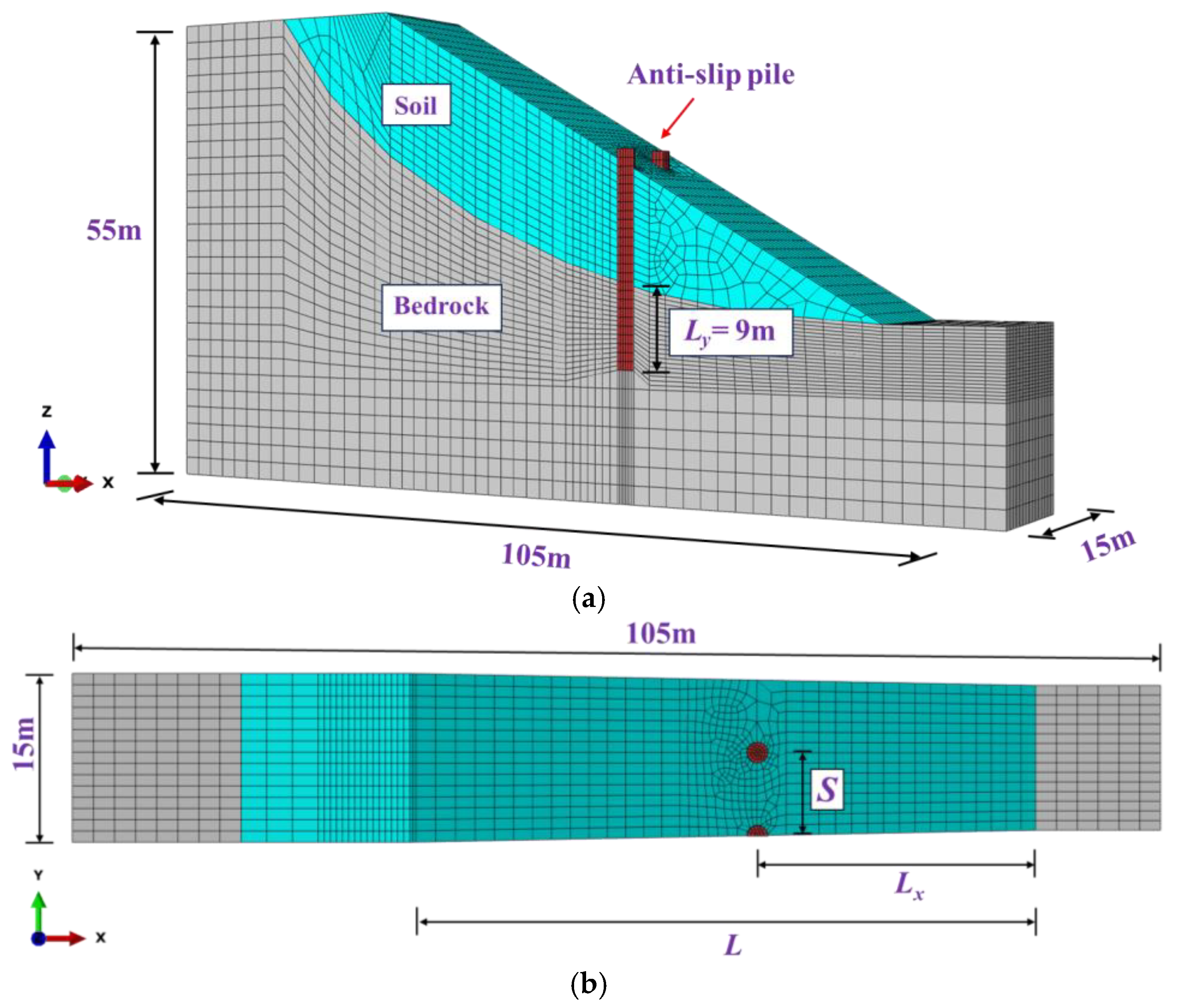
2.1. Numerical Model
- (1)
- Mathematical formulation
- (2)
- Boundary conditions
- (3)
- Element types and sizes
- (4)
- The landslide parameters
- (5)
- Contact surface parameters
2.2. Simulation Scheme
3. Results and Discussion
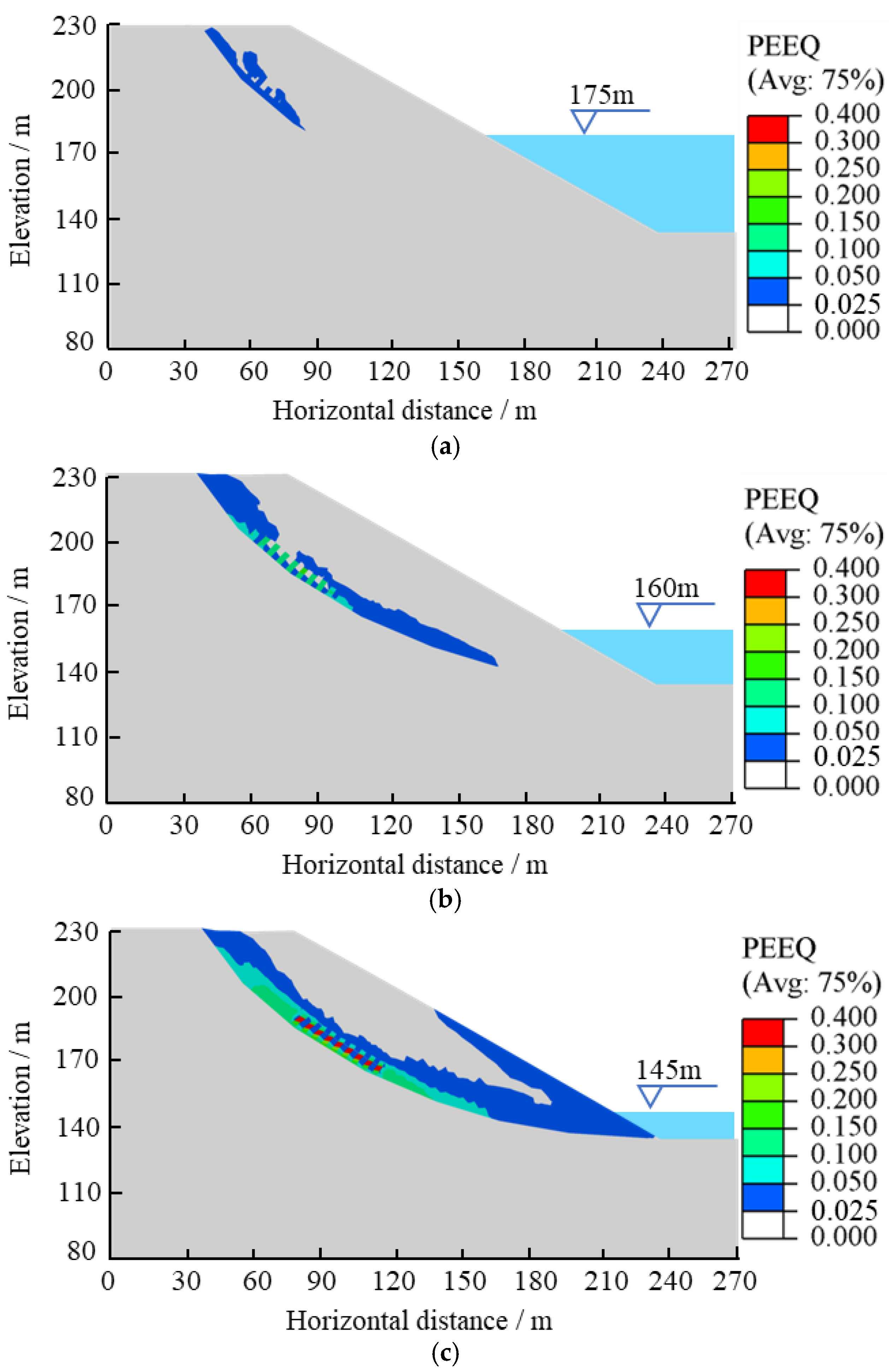
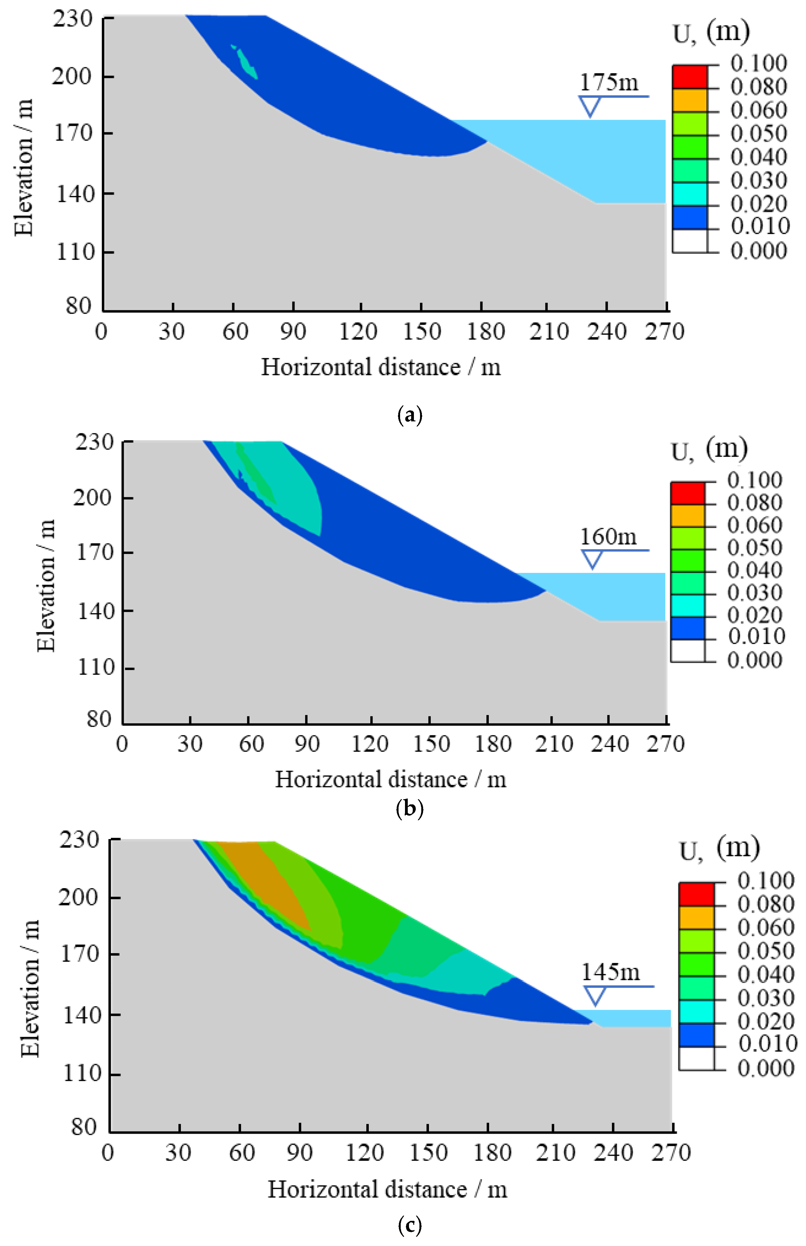
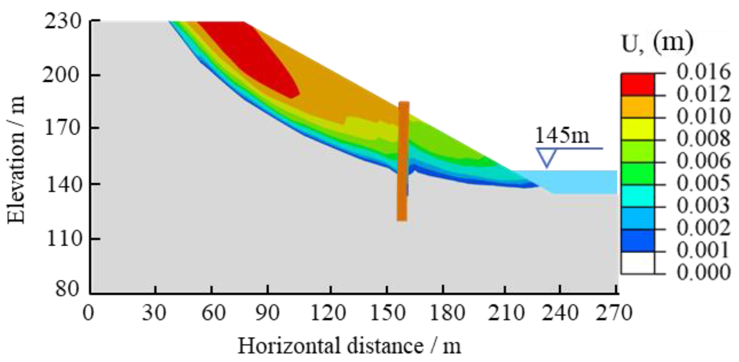
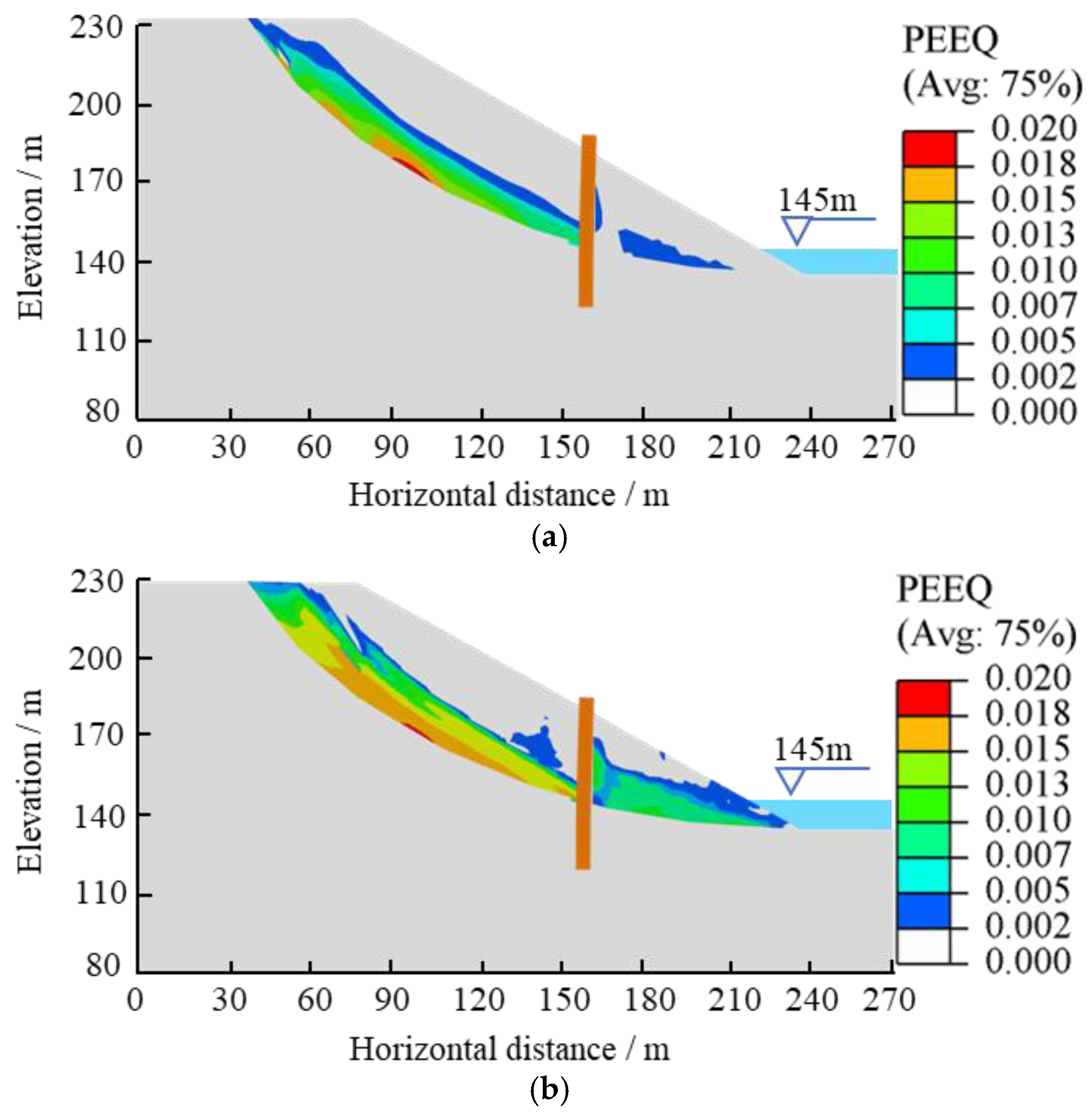
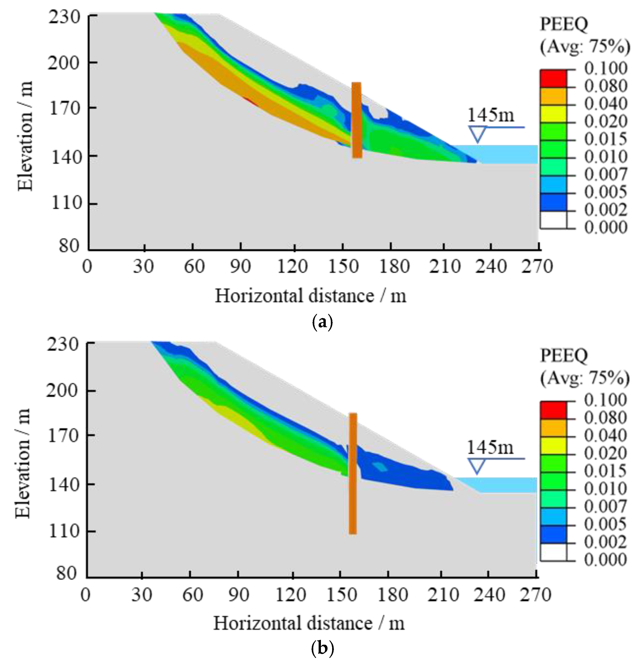
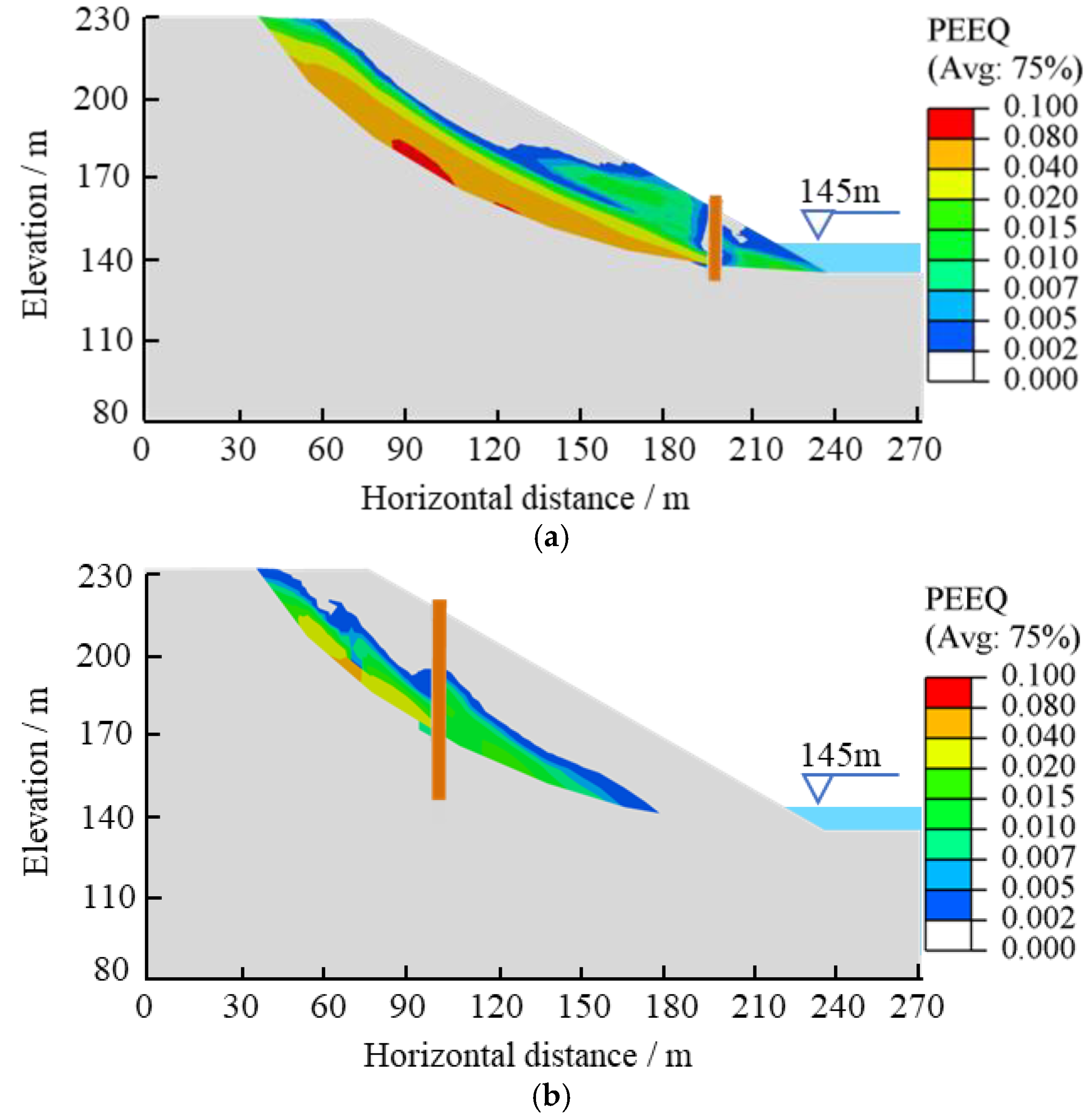
3.1. Analysis of Landslide Deformation Mechanism
- (1)
- Define the field variable, usually the strength reduction factor.
- (2)
- Define the material properties that vary with the field variables.
- (3)
- Set the boundary conditions and obtain the numerical equilibrium.
- (4)
- Change and increase the field variable (i.e., the reduction factor) until the numerical calculation does not converge.
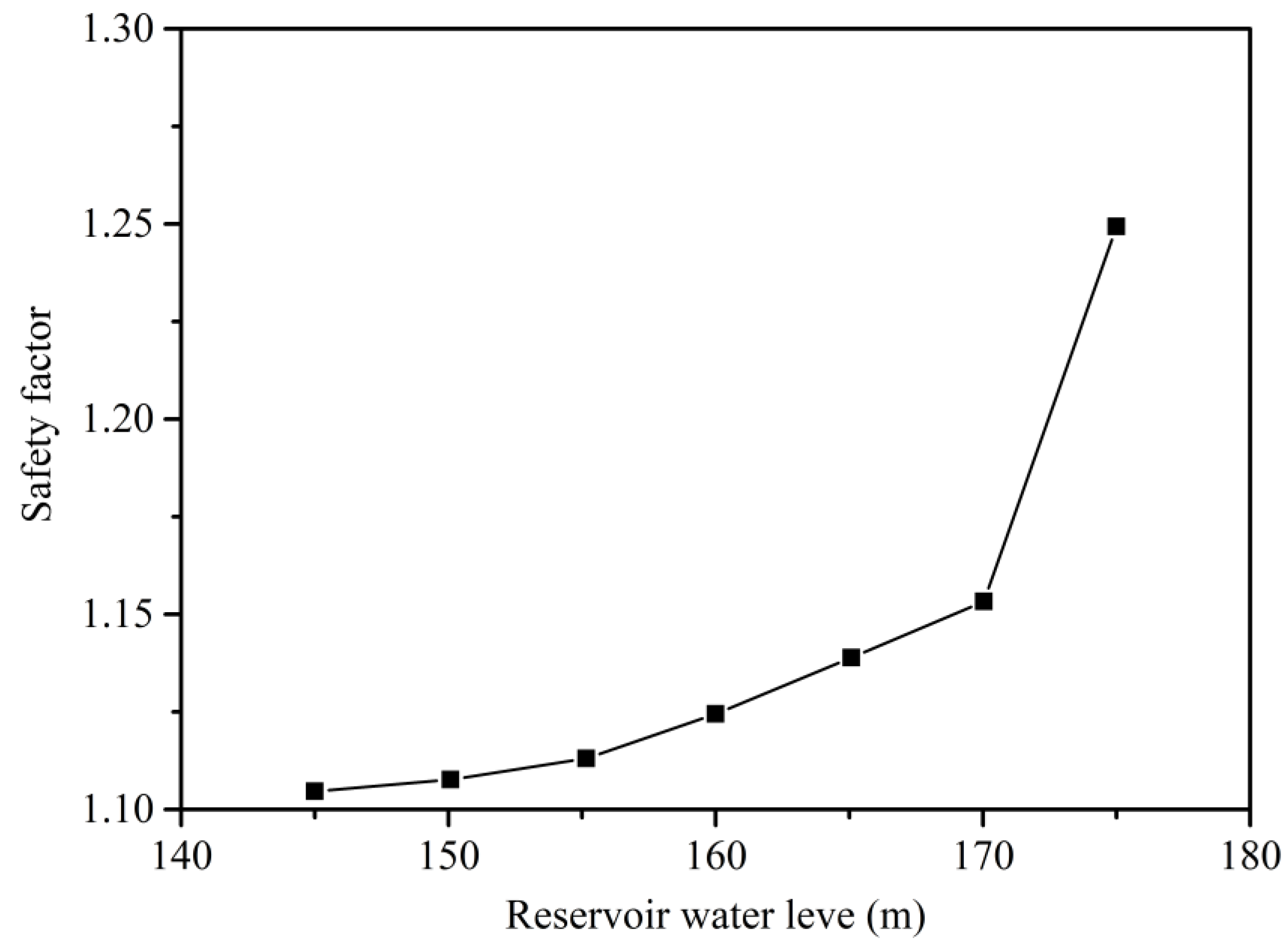
3.2. Analysis of Anti-Slide Pile Reinforcement Effects
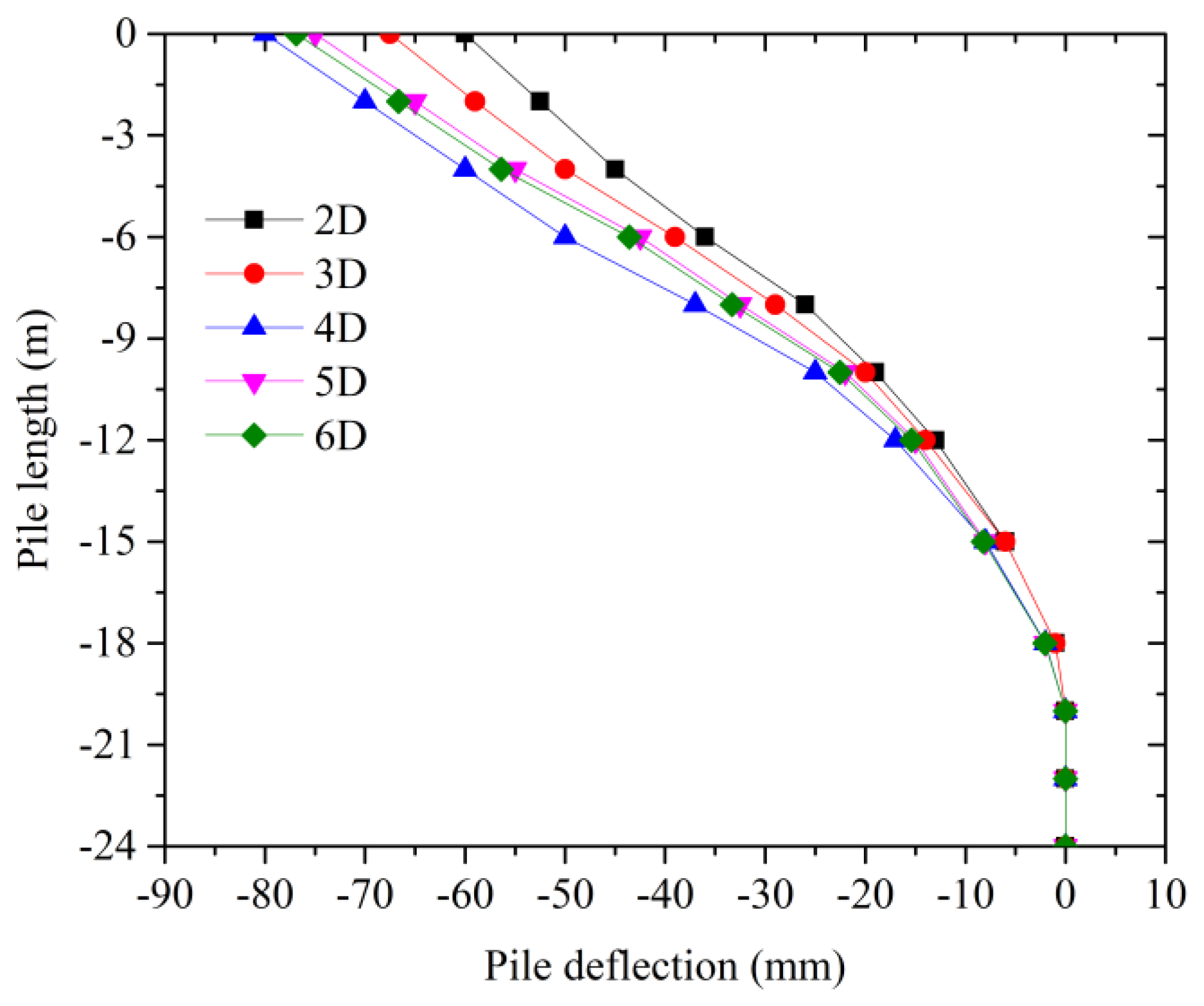
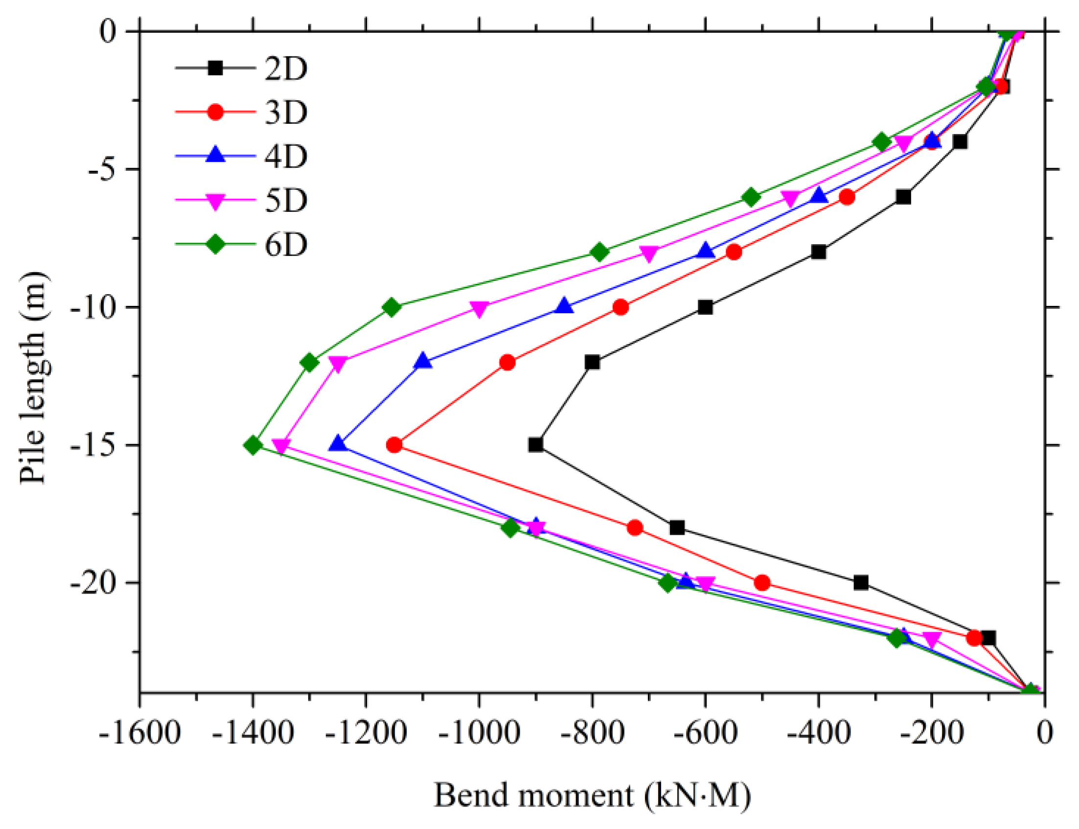
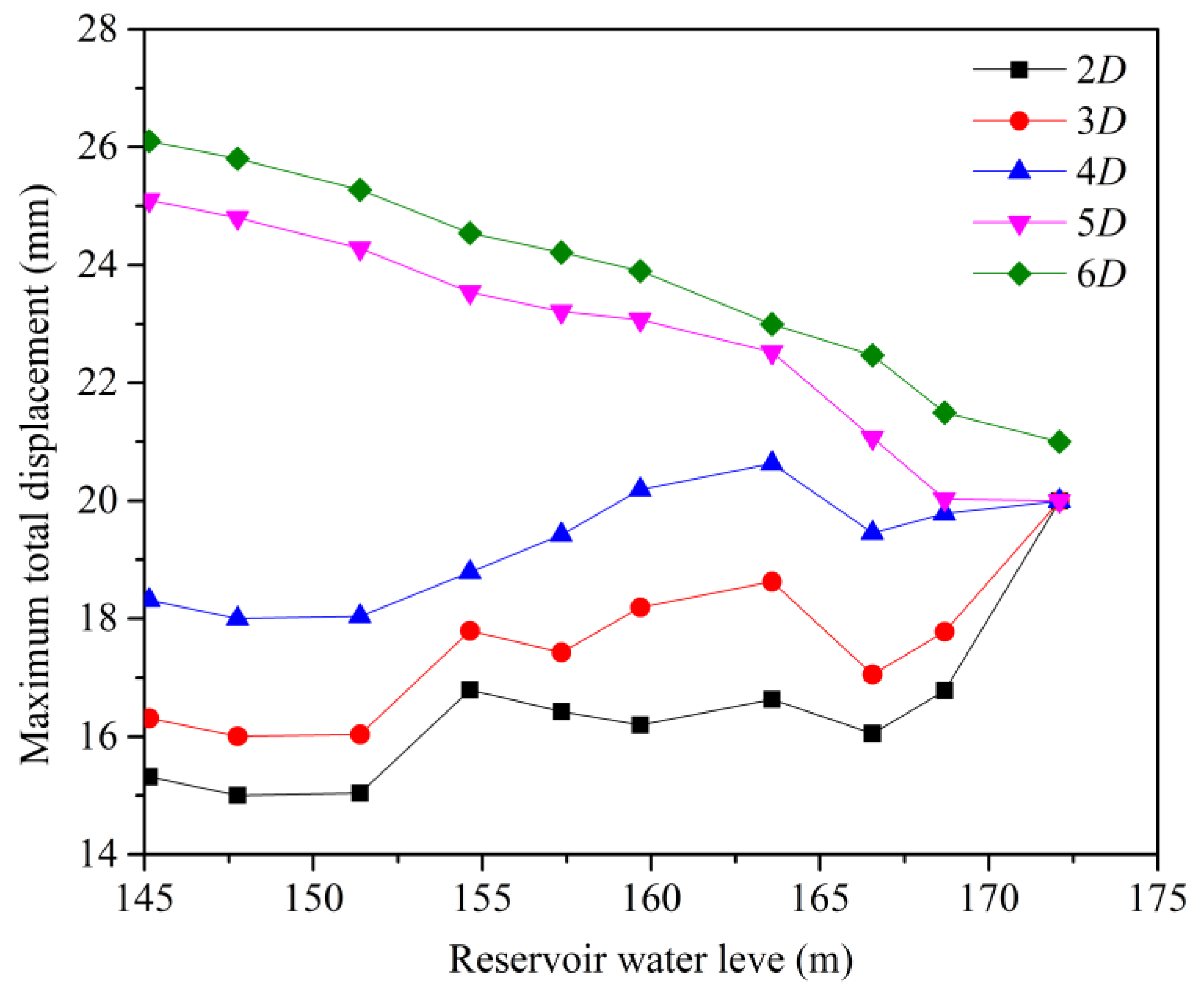
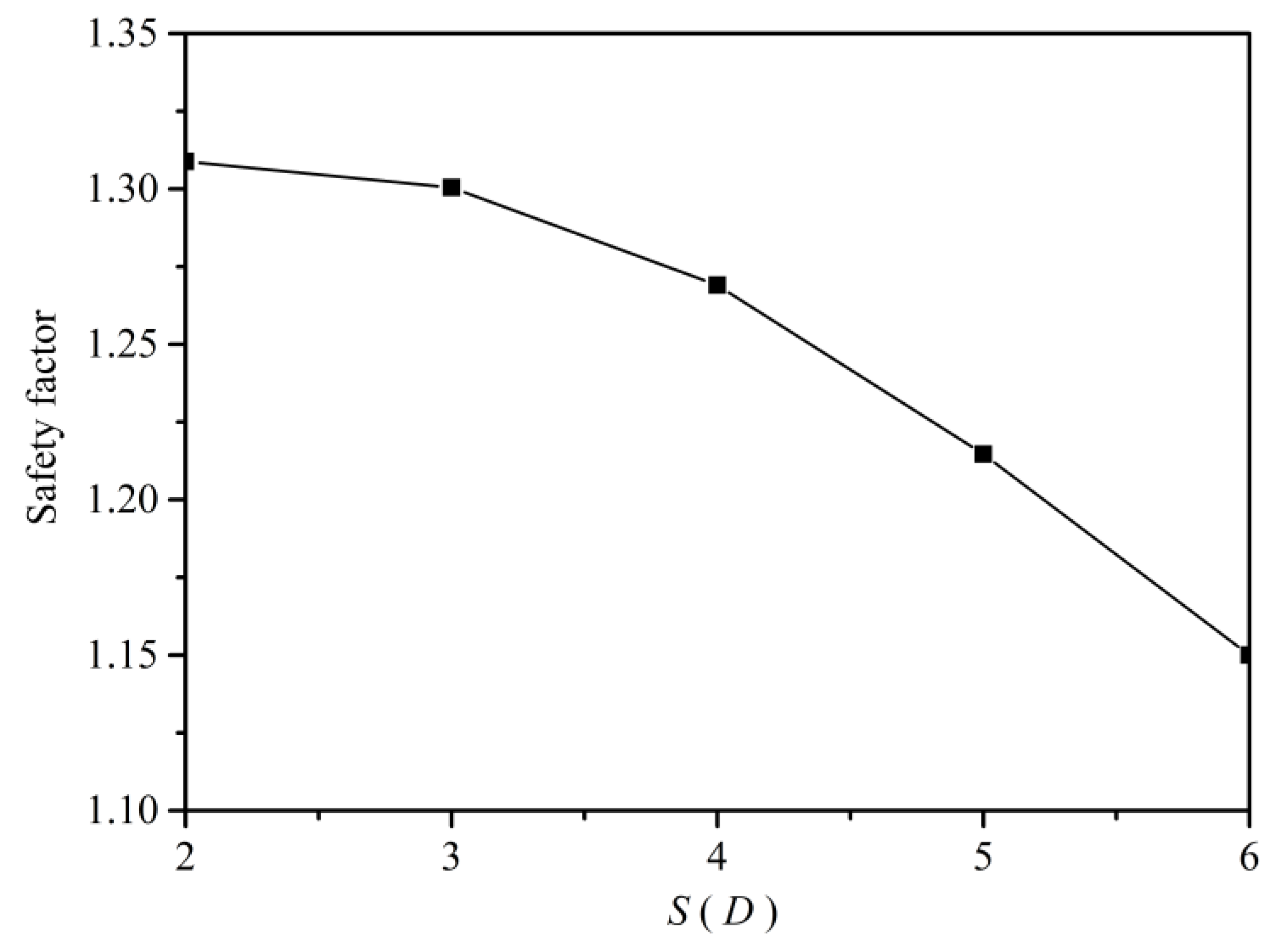
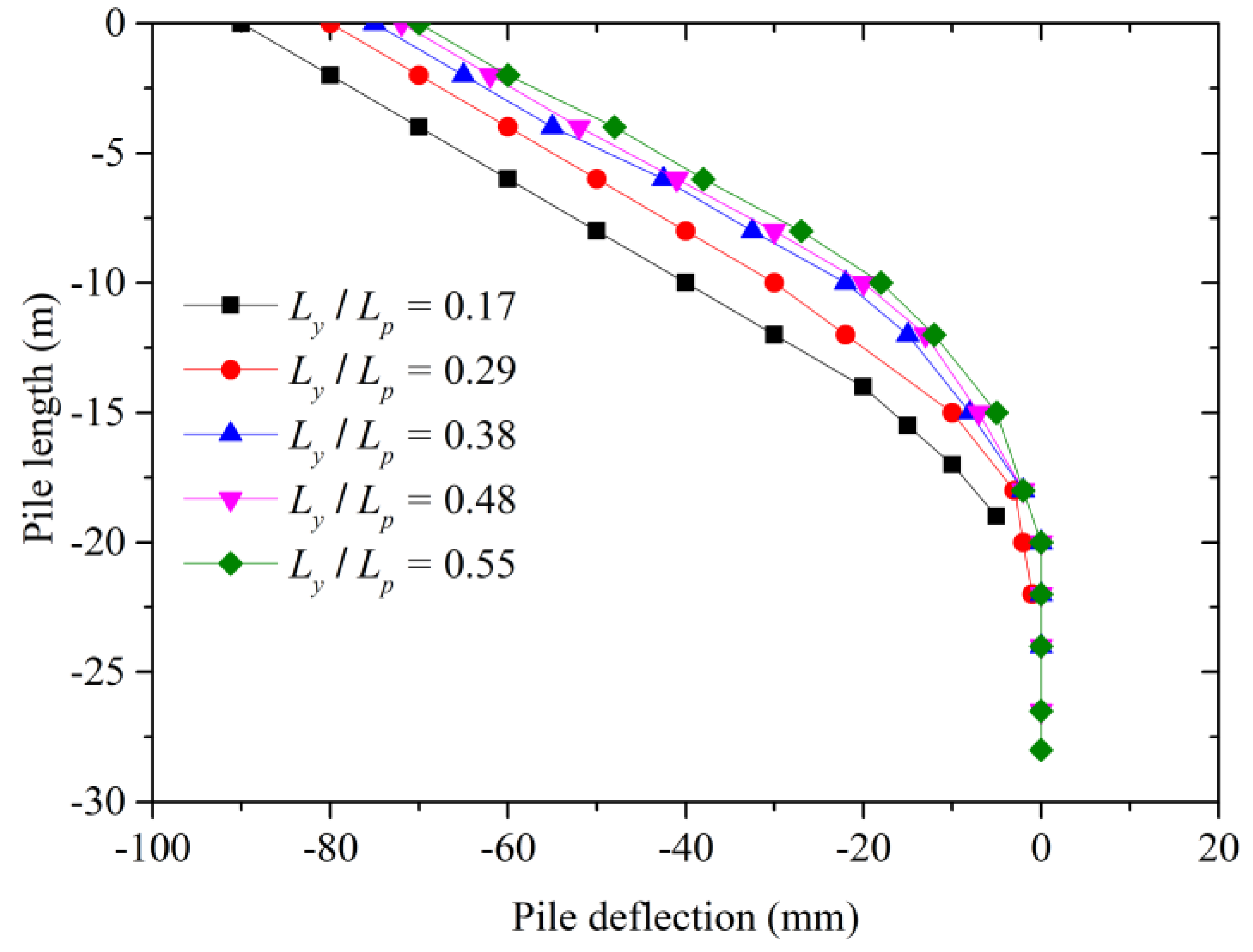
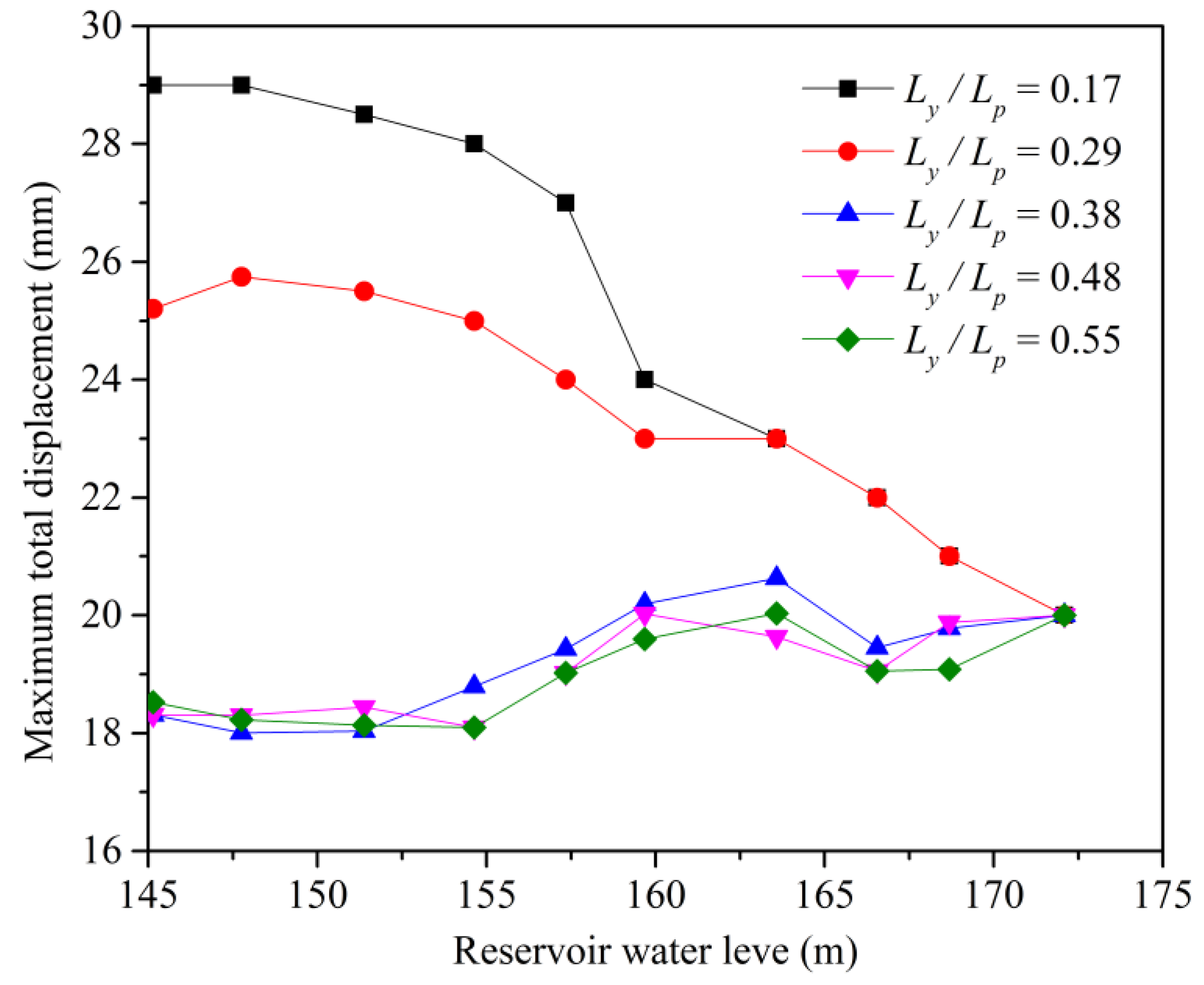
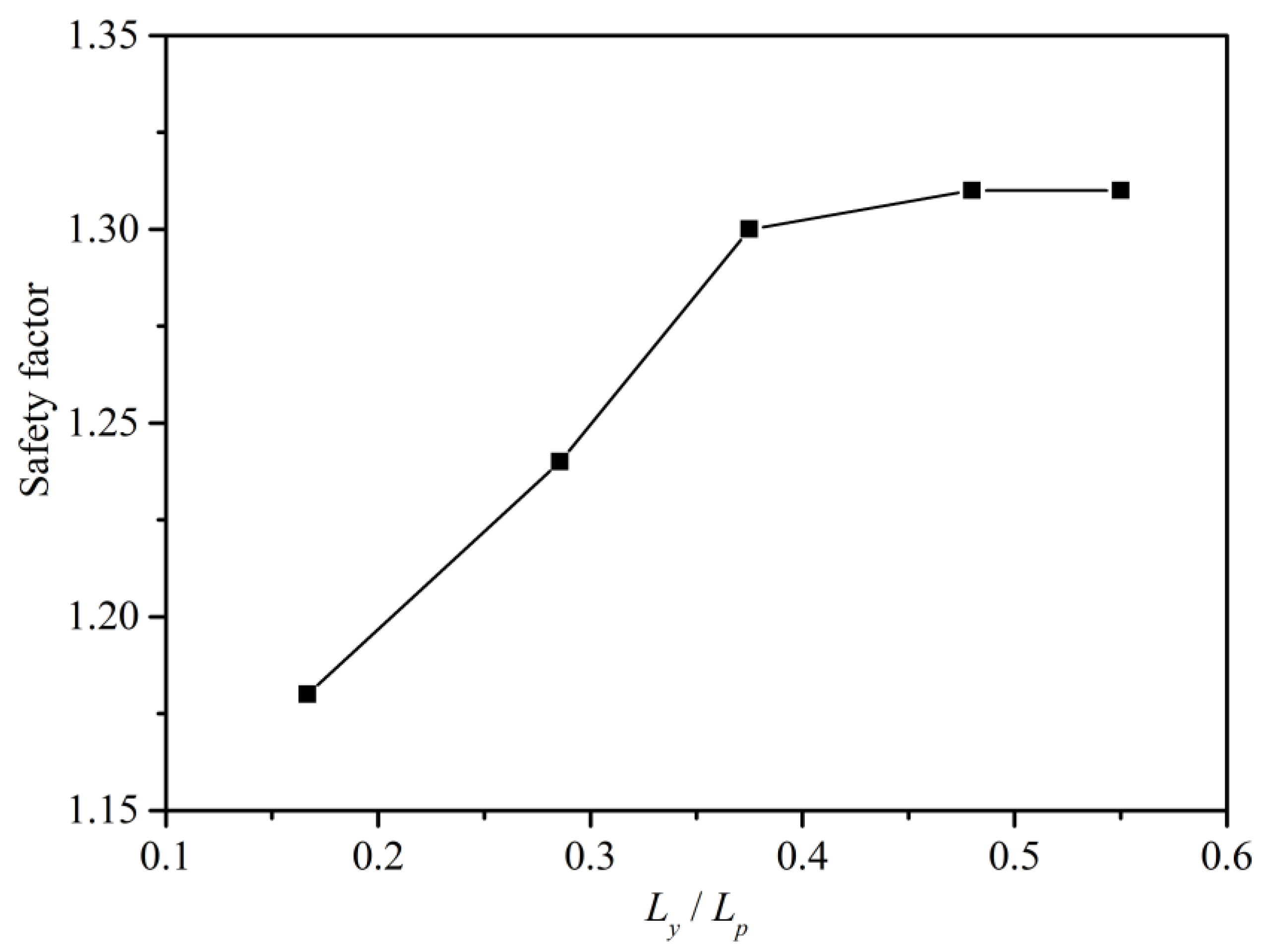
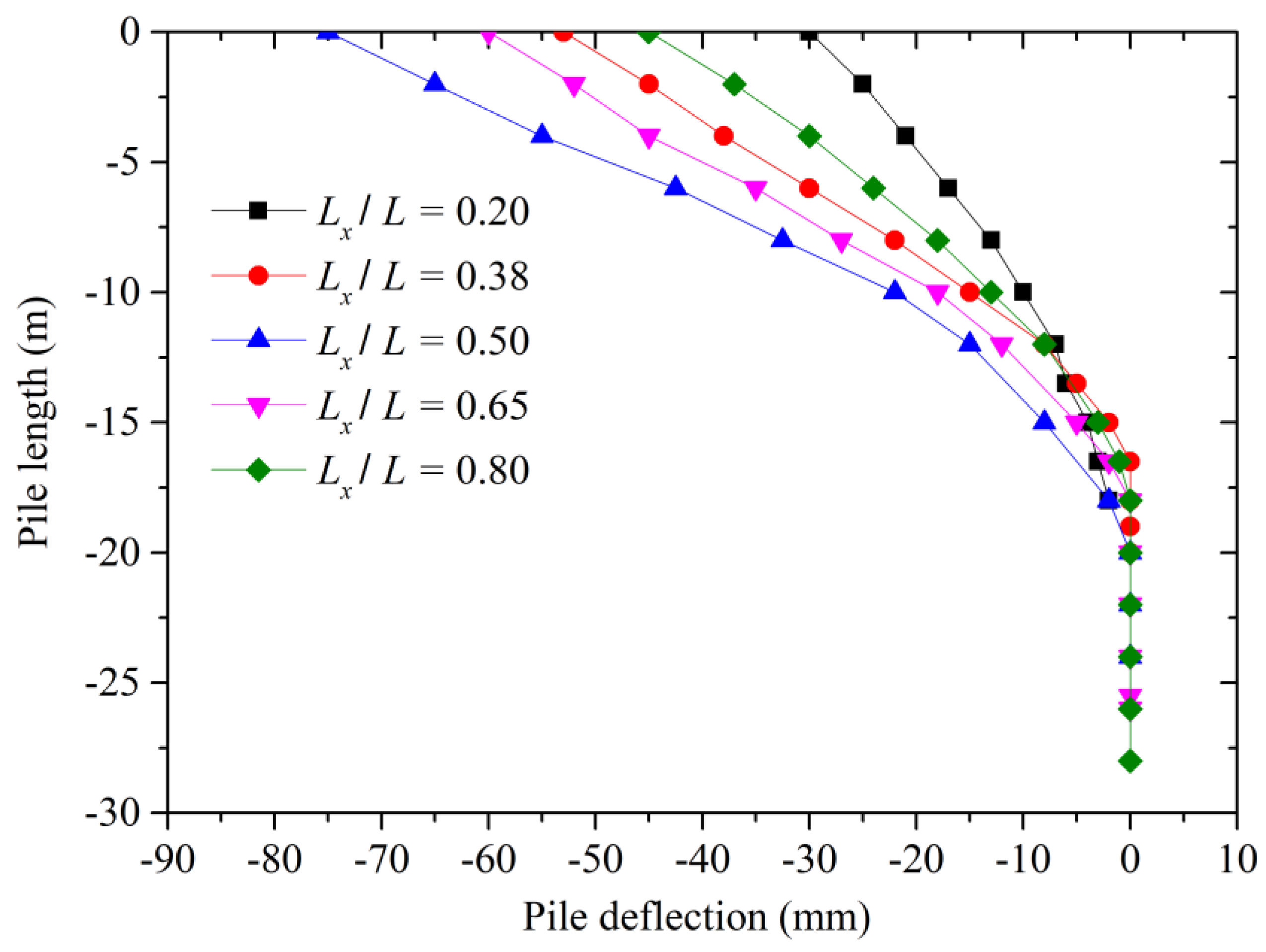
3.3. Parameter Analysis
- (a)
- Pile spacing
- (b)
- Embedment depth
- (c)
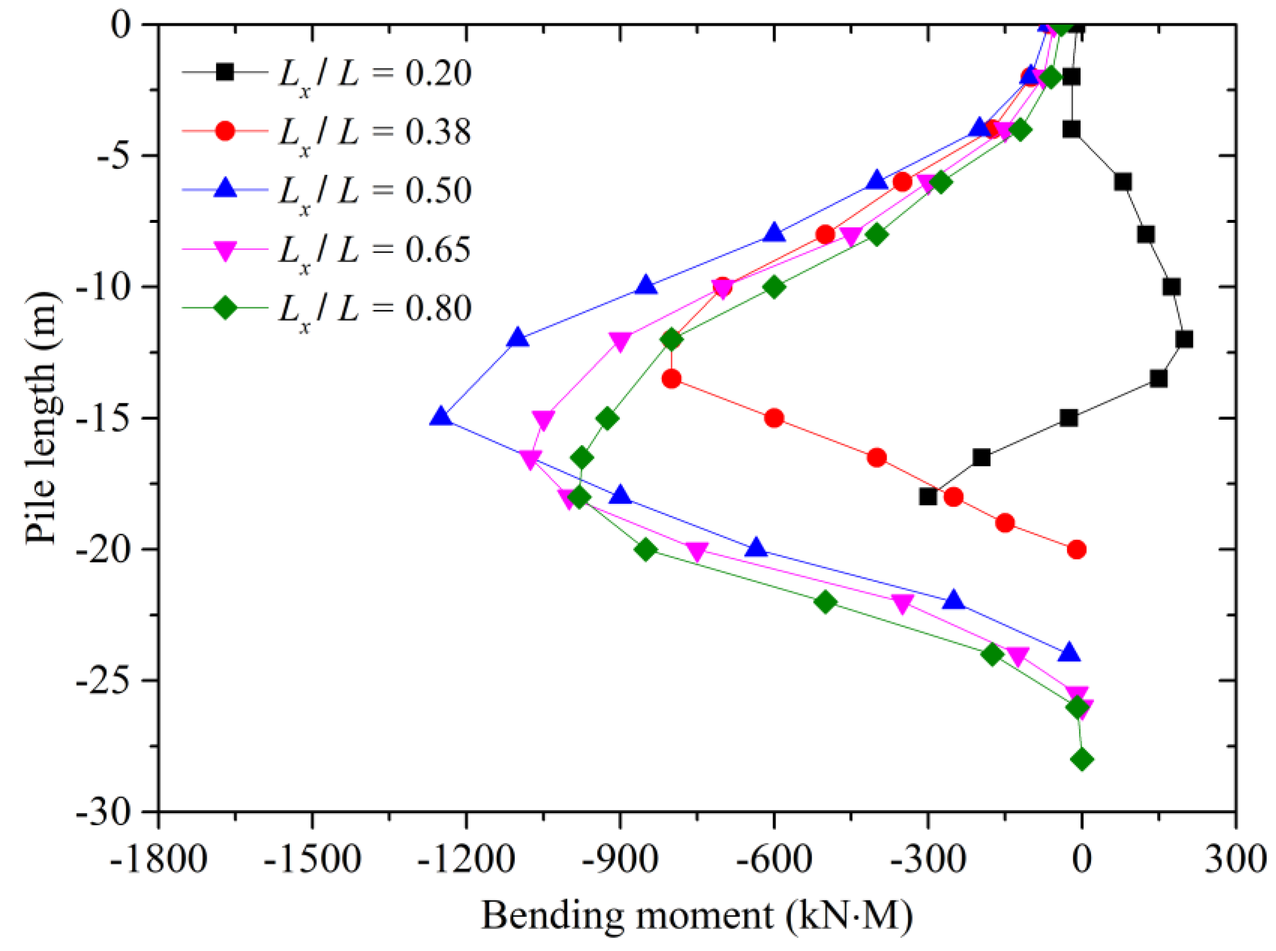
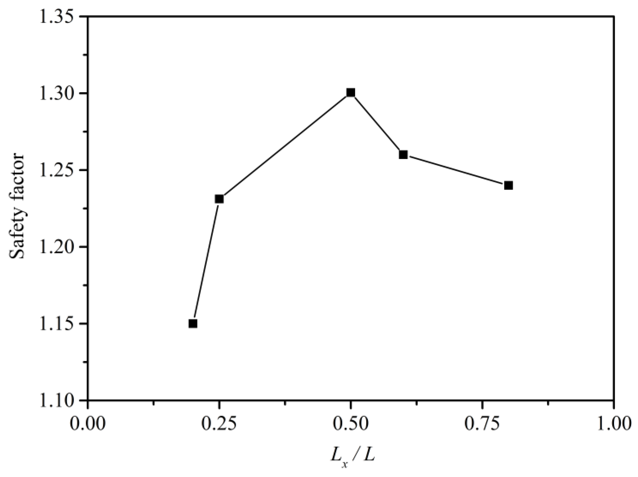
- Pile position
4. Conclusions
Author Contributions
Funding
Data Availability Statement
Conflicts of Interest
References
- Zong, X.Z.; Tao, L.; Shu, Z.; Duan, H.; Li, S.; Wang, J.; Deng, Y. A novel method to evaluate the time-dependent stability of reservoir landslides: Exemplified by Outang landslide in the Three Gorges Reservoir. Landslides 2023, 20, 1731–1746. [Google Scholar]
- Li, Y.; Xie, X.; Jin, B.; Chen, L.; Liang, X.; Yin, K. Comprehensive risk management of reservoir landslide-tsunami hazard chains: A case study of the Liangshuijing landslide in the Three Gorges Reservoir area. Landslides 2024, 22, 671–691. [Google Scholar] [CrossRef]
- Farooq, M.A.; Falak, S.; Ehtisham, M. Evaluation of landslide hazards potential at Dasu dam site and its reservoir area. Environ. Earth Sci. 2023, 82, 183. [Google Scholar]
- Muhammad, K.; Xiewen, H.; Awais, M.H.; Sanaullah, M.; Ali, R. Dynamic Response and Deformation Behavior of Kadui-2 Landslide Influenced by Reservoir Impoundment and Rainfall, Baoxing, China. J. Earth Sci. 2023, 34, 911–923. [Google Scholar]
- Song, K.; Wang, F.; Yi, Q.; Lu, S. Landslide deformation behavior influenced by water level fluctuations of the Three Gorges Reservoir (China). Eng. Geol. 2018, 247, 58–68. [Google Scholar] [CrossRef]
- Xia, M.; Ren, G.M.; Ma, X.L. Deformation and mechanism of landslide influenced by the effects of reservoir water and rainfall, Three Gorges, China. Nat. Hazards 2013, 68, 467–482. [Google Scholar] [CrossRef]
- Jia, G.; Zhan, T.L.; Chen, Y.; Fredlund, D. Performance of a large-scale landslide model subjected to rising and lowering water levels. Eng. Geol. 2009, 106, 92–103. [Google Scholar] [CrossRef]
- Huang, X.; Guo, F.; Deng, M.; Yi, W.; Huang, H. Understanding the deformation mechanism and threshold reservoir level of the floating weight-reducing landslide in the Three Gorges Reservoir Area, China. Landslides 2020, 17, 2879–2894. [Google Scholar] [CrossRef]
- Tang, M.; Xu, Q.; Yang, H.; Li, S.; Iqbal, J.; Fu, X.; Huang, X.; Cheng, W. Activity law and hydraulics mechanism of landslides with different sliding surface and permeability in the Three Gorges Reservoir Area, China. Eng. Geol. 2019, 260, 105212. [Google Scholar] [CrossRef]
- Zhao, N.; Hu, B.; Yan, E.; Xu, X.; Yi, Q. Research on the creep mechanism of Huangniba landslide in the Three Gorges Reservoir Area of China considering the seepage–stress coupling effect. Bull. Eng. Geol. Environ. 2019, 78, 4107–4121. [Google Scholar] [CrossRef]
- Zangerl, C.; Eberhardt, E.; Perzlmaier, S. Kinematic behaviour and velocity characteristics of a complex deep-seated crystal-line rockslide system in relation to its interaction with a dam reservoir. Eng. Geol. 2010, 112, 53–67. [Google Scholar] [CrossRef]
- Lin, J.; Yu, S.; Luo, Y.; Xu, T.; Lin, Y.; Zheng, W.; Li, W.; Wang, Y. Research on Stability of Dam Substation on Inclined Soft Soil Foundation Reinforced by Pile Foundation. Water 2023, 15, 3527. [Google Scholar] [CrossRef]
- Wen, Z.; Xu, W.; Yuan, B.; Zhang, L.; Liang, Z. Numerical Analysis of Anti-Slide Pile Reinforcement for Landslide Stability Under Rainfall Conditions. Buildings 2025, 15, 638. [Google Scholar] [CrossRef]
- Zhang, Q.; Hu, J.; Du, Y.; Gao, Y.; Li, J. A laboratory and field-monitoring experiment on the ability of anti-slide piles to prevent buckling failures in bedding landslides. Environ. Earth Sci. 2021, 80, 44. [Google Scholar] [CrossRef]
- Zhang, H.; Xing, H.-F.; Xue, D.-R.; Tannant, D. Centrifuge and numerical modeling of h-type anti-slide pile reinforced soil-rock mixture landslide. J. Mt. Sci. 2023, 20, 1441–1457. [Google Scholar] [CrossRef]
- Song, Y.; Hong, W.; Woo, K. Behavior and analysis of stabilizing piles installed in a cut landslide during heavy rainfall. Eng. Geol. 2012, 129–130, 56–67. [Google Scholar] [CrossRef]
- Wang, L.; Zhang, G. Centrifuge model test study on pile reinforcement behavior of cohesive soil landslides under earthquake conditions. Landslides 2014, 11, 213–223. [Google Scholar] [CrossRef]
- Zhang, G.; Wang, L. Integrated analysis of a coupled mechanism for the failure processes of pile-reinforced landslides. Acta. Geotech. 2016, 11, 941–952. [Google Scholar] [CrossRef]
- Lirer, S. Landslide stabilizing piles: Experimental evidences and numerical interpretation. Eng. Geol. 2012, 149–150, 70–77. [Google Scholar] [CrossRef]
- Won, J.; You, K.; Jeong, S.; Kim, S. Coupled effects in stability analysis of pile–landslide systems. Comput. Geotech. 2005, 32, 304–315. [Google Scholar] [CrossRef]
- ABAQUS. Abaqus 6.14 Standard; Dassault Systemes Simulia Corp: Providence, RI, USA, 2014. [Google Scholar]
- Zienkiewicz, O.C.; Humpheson, C.; Lewis, R.W. Associated and non associated viscoplasticity in soil mechanics. Geotechnique 1975, 25, 671–689. [Google Scholar] [CrossRef]
- Dawson, E.M.; Roth, W.H.; Drescher, A. Slope stability analysis by strength reduction. Geotechnique 1999, 49, 835–840. [Google Scholar] [CrossRef]
- Yin, Y.; Huang, B.; Wang, W.; Wei, Y.; Ma, X.; Ma, F.; Zhao, C. Reservoir-induced landslides and risk control in Three Gorges Project on Yangtze River. China. J. Rock Mech. Geotech. 2016, 8, 577–595. [Google Scholar] [CrossRef]
- Luo, S.-L.; Huang, D.; Peng, J.-B.; Aierken, A.; Li, Z.; Kuang, X.-B.; Tomás, R. Performance and application of a novel drainage anti-slide pile on accumulation landslide with a chair-like deposit-bedrock interface in the Three Gorges Reservoir area, China. Comput. Geotech. 2023, 155, 105199. [Google Scholar] [CrossRef]
- Pulko, B.; Majes, B.; Mikoš, M. Reinforced concrete shafts for the structural mitigation of large deep-seated landslides: An experience from the Macesnik and the Slano blato landslides (Slovenia). Landslides 2014, 11, 81–91. [Google Scholar] [CrossRef]
- Chen, L.; Guo, H.; Gong, P.; Yang, Y.; Zuo, Z.; Gu, M. Landslide susceptibility assessment using weights-of-evidence model and cluster analysis along the highways in the Hubei section of the Three Gorges Reservoir Area. Comput. Geosci. 2021, 156, 104899. [Google Scholar] [CrossRef]


| Material | Density ρ (kN/m3) | Friction Angle φ (°) | Cohesion c (kPa) | Permeability Coefficient k (m/d) | Elasticity Modulus G (MPa) | Poisson’s Ratio υ | |||
|---|---|---|---|---|---|---|---|---|---|
| Natural Saturated | Natural Saturated | Natural Saturated | |||||||
| Soil | 16.8 | 22.0 | 20 | 18 | 15 | 3 | 7.5 | 22.0 | 0.33 |
| Bedrock | 26.0 | 27.0 | 26 | 24 | 40 | 36 | 0.01 | 28,000 | 0.25 |
| Parameter | Symbol | Unit | Value |
|---|---|---|---|
| Diameter | m | 2.0 | |
| Density | ρ | kN/m3 | 24.0 |
| Elasticity modulus | MPa | 26,000 | |
| Effective Poisson’s ratio | 0.13 |
Disclaimer/Publisher’s Note: The statements, opinions and data contained in all publications are solely those of the individual author(s) and contributor(s) and not of MDPI and/or the editor(s). MDPI and/or the editor(s) disclaim responsibility for any injury to people or property resulting from any ideas, methods, instructions or products referred to in the content. |
© 2025 by the authors. Licensee MDPI, Basel, Switzerland. This article is an open access article distributed under the terms and conditions of the Creative Commons Attribution (CC BY) license (https://creativecommons.org/licenses/by/4.0/).
Share and Cite
Yang, G.; Wu, Z.; Zhang, L.; Hou, J.; Tong, S.; Liu, F.; Zheng, Y. A Study on the Deformation Mechanism of a Landslide Reinforced with an Anti-Slip Pile Under the Effect of Reservoir Water Level Decline. Water 2025, 17, 1390. https://doi.org/10.3390/w17091390
Yang G, Wu Z, Zhang L, Hou J, Tong S, Liu F, Zheng Y. A Study on the Deformation Mechanism of a Landslide Reinforced with an Anti-Slip Pile Under the Effect of Reservoir Water Level Decline. Water. 2025; 17(9):1390. https://doi.org/10.3390/w17091390
Chicago/Turabian StyleYang, Gang, Zhuolin Wu, Lin Zhang, Jingfeng Hou, Shen Tong, Fei Liu, and Yong Zheng. 2025. "A Study on the Deformation Mechanism of a Landslide Reinforced with an Anti-Slip Pile Under the Effect of Reservoir Water Level Decline" Water 17, no. 9: 1390. https://doi.org/10.3390/w17091390
APA StyleYang, G., Wu, Z., Zhang, L., Hou, J., Tong, S., Liu, F., & Zheng, Y. (2025). A Study on the Deformation Mechanism of a Landslide Reinforced with an Anti-Slip Pile Under the Effect of Reservoir Water Level Decline. Water, 17(9), 1390. https://doi.org/10.3390/w17091390