Article

Assessing the Potential of Magnetic Water Treatment of Groundwater for Calcium Carbonate Scale Mitigation in Drinking Water Distribution Networks

by
David Sanchez
1,*,
Eduardo Herrera-Peraza
2,
Carmen Navarro-Gomez
1,* and
Jesus Ruben Sanchez-Navarro
2
1
Faculty of Engineering, Autonomous University of Chihuahua, Circuito Universitario 31109, Campus Uach II, Chihuahua 31125, Mexico
2
Department of Environmental and Energy, Center for Advanced Materials Research S.C., Chihuahua 31109, Mexico
*
Authors to whom correspondence should be addressed.
Water 2025, 17(9), 1265; https://doi.org/10.3390/w17091265
Submission received: 18 March 2025 / Revised: 12 April 2025 / Accepted: 14 April 2025 / Published: 24 April 2025
(This article belongs to the Special Issue Groundwater Flow and Transport Modeling in Aquifer Systems)

Abstract

:
Mineral scaling and corrosion pose significant challenges in groundwater distribution, increasing hydraulic resistance, reducing flow rates, and raising operational costs. Magnetic water treatment (MWT) has gained attention as a non-chemical method to mitigate scale formation by promoting the transformation of calcite, a hard and adherent CaCO3 polymorph, into aragonite, a softer and less adherent form. In Chihuahua, Mexico, mineral scaling has disrupted the drinking water distribution system, reducing flow and impairing service. This study evaluates MWT’s potential to mitigate scaling by analyzing magnetized water treated under various MWT configurations. Comparative analyses were conducted via XRD and SEM to assess changes in calcium carbonate polymorphs. Finite element method (FEM) simulations in COMSOL Multiphysics 6.0 were used to evaluate the magnetic field distribution. The results show no systematic trend in CaCO3 polymorph transformation following MWT exposure, and FEM simulations indicate negligible magnetic field gradients in certain configurations. These findings highlight the critical role of optimizing magnetic field alignment and gradient strength. Future research should refine MWT configurations and incorporate real-time monitoring to enhance its effectiveness in scale prevention.

1. Introduction

Mineral scale and corrosion are among the most significant challenges in water supply systems that rely on groundwater sources, particularly affecting both well infrastructure and downstream distribution networks. Scaling arises from the precipitation and deposition of inorganic salts, such as calcium carbonate (CaCO3), on contact surfaces [1]. This process obstructs water flow, blocks pipes, and disrupts water delivery. Corrosion and scaling in drinking water distribution systems accelerate system degradation, impact water quality for consumers, and result in considerable maintenance and replacement costs [2,3].
The accumulation of mineral scale within pipelines contributes to increased hydraulic resistance and reduced flow rates, and decreases overall network efficiency. These effects translate into higher operational costs driven by increased energy consumption, more frequent repairs, shorter equipment lifespans, and interruptions to production processes. Collectively, these issues result in annual financial losses estimated to reach billions of dollars [4].
Scale formation is particularly problematic on critical surfaces, including pipelines, heat transfer equipment, condenser tubes, and membranes [5,6]. While traditional chemical treatments for controlling scales are effective, they are often costly and can alter the chemical composition of the treated water. This has spurred interest in exploring alternative, cost-efficient, and environmentally friendly physical methods for scale prevention and control [7].
Magnetic water treatment (MWT) has emerged as a promising nonchemical alternative for scale control in water systems [3]. Multiple experimental studies have demonstrated that MWT can reduce scale deposition and modify CaCO3 crystallization, often resulting in softer, more easily removable forms [7,8,9]. For instance, Wang et al. [3] found that a 300 mT magnetic field lowered water’s specific heat and boiling point, increasing evaporation by nearly 39%. Alimi et al. [10] and Othman et al. [7] observed shifts from calcite to aragonite and significant hardness reductions, respectively, depending on magnetic field intensity and flow conditions. However, contrasting results reported by Baker and Judd [11] and Ali [12] suggest that factors such as field configuration, turbulence, and water chemistry critically influence outcomes.
These discrepancies underscore the need for a systematic evaluation of magnetic field strength, geometry, pH, ionic strength, and supersaturation [9,10,13,14,15,16,17,18]. While MWT has been studied across scales, many experiments lack thorough characterizations of magnetic field parameters, and real-world validations are scarce. Studies by Tai et al. [19], Liu et al. [20], and Piyadasa et al. [21] further emphasize how variations in intensity, operational mode, and design significantly alter crystallization outcomes.
Despite reports that MWT may promote bulk phase CaCO3 formation over surface scaling, the mechanisms remain controversial. A commonly proposed explanation involves a transformation from calcite to aragonite, a softer, less adherent polymorph, yet this hypothesis is debated due to the absence of magnetic moments in water and CaCO3 molecules [9,13,14]. Inconsistent findings across studies continue to highlight the importance of standardized testing protocols and the careful control of water chemistry, field configurations, and hydraulic conditions [22,23,24,25,26,27,28,29,30,31].
To address this, Michael Coey (2012) [26] proposed a theoretical framework to explain the effects of magnetic fields on water, introducing a criterion to predict the effectiveness of MWT. This theory emphasizes the magnetic field gradient (∇B) as the critical factor, rather than the field’s magnitude. Coey’s model provides valuable insights into optimizing MWT systems by considering parameters such as magnetic field gradient, magnet length, and water flow velocity [26]. The effectiveness of MWT is governed by
C = 2 ( L / v ) f p a B 1
L: length of the magnet.
v: flow velocity of the water.
fp: a fixed characteristic frequency (42.6 MHz/T).
a: a fixed characteristic distance (0.25 nm).
∇B: gradient of the magnetic field (T/m).
By optimizing parameters such as increasing magnet length, decreasing water flow velocity, or enhancing the magnetic field gradient, MWT effectively promotes the transformation of CaCO3 from calcite to aragonite [24].
The effectiveness of MWT in mitigating scaling is closely tied to aragonite formation. Analytical techniques such as X-ray diffraction (XRD) are essential for quantifying the proportions of calcite and aragonite, providing insights into the transformation process. Additionally, scanning electron microscopy (SEM) enables the identification of crystal morphology, distinguishing the equiaxed structure of calcite from the acicular (needle-like) structure of aragonite.
In the city of Chihuahua, clogging caused by mineral scaling has significantly disrupted the drinking water distribution system, obstructing flow and impairing service delivery. This issue imposes a substantial economic burden on water utilities while creating social challenges due to inconsistent access to water. Drinking water distribution systems are critical for maintaining water quality; however, they are frequently compromised by problems such as corrosion, scaling, and the accumulation of deposits. These issues not only affect system functionality, but also pose risks to public health, erode consumer confidence in the water supply, and escalate the costs associated with providing water services.
Despite the widespread recognition of such challenges, effective and practical mitigation strategies remain underdeveloped. The lack of standardization in magnetic field reporting, coupled with inconsistent experimental results, has hindered the broader adoption of MWT. This highlights the need for continued research to resolve these uncertainties and improve the implementation of MWT under real-world conditions. This study aims to address these limitations by implementing multiple types of controlled and well-characterized MWT systems under defined hydraulic and chemical conditions. It seeks to clarify the mechanism of CaCO3 polymorphic transformation and assess the practical applicability of MWT in municipal water distribution systems. Furthermore, it explores how treatment effectiveness is influenced by magnetic field configuration, water composition, and flow regime, and evaluates technical considerations to support reliable and efficient system operation.

2. Materials and Methods

2.1. Study Area

The study area is situated in the city of Chihuahua, located in northern Mexico at coordinates 28°40.8′ N and 106°2.5′ W. The study area covers a district meter (DMA) with elevations ranging from 1436 to 1488 m.a.s.l., featuring a noticeable slope from northwest to southeast. This DMA has experienced ongoing challenges in its drinking water supply, largely due to CaCO3 incrustation in various sections of the district’s pipeline network.
The drinking water supply in the study area is continuous throughout the day, with demand fluctuating in distinct patterns. The peak consumption periods occur between 6:00 and 9:00 am and between 4:00 and 7:00 pm. The water system serves a total of 794 accounts (Figure 1), representing approximately 2278 inhabitants, based on data from INEGI [32].

Water Collection and Treatment

For this study, water was sourced from the main storage tank located at the upstream end of the DMA, in accordance with the specifications provided by the Municipal Water and Sanitation Board (JMAS). Water samples were divided into two categories—magnetized water (MW) and non-magnetized water (NMW). The NMW, serving as a reference, was collected from the highest point closest to the main tank within the DMA.
Magnetized water was treated using MWT systems configured in multiple setups to assess their effectiveness. The comparative analysis between NMW and MW was performed to evaluate potential changes in water properties induced by magnetic field treatments.
Three distinct magnetization systems were used to generate MW, each varying in configuration and magnetic field strength, as follows:
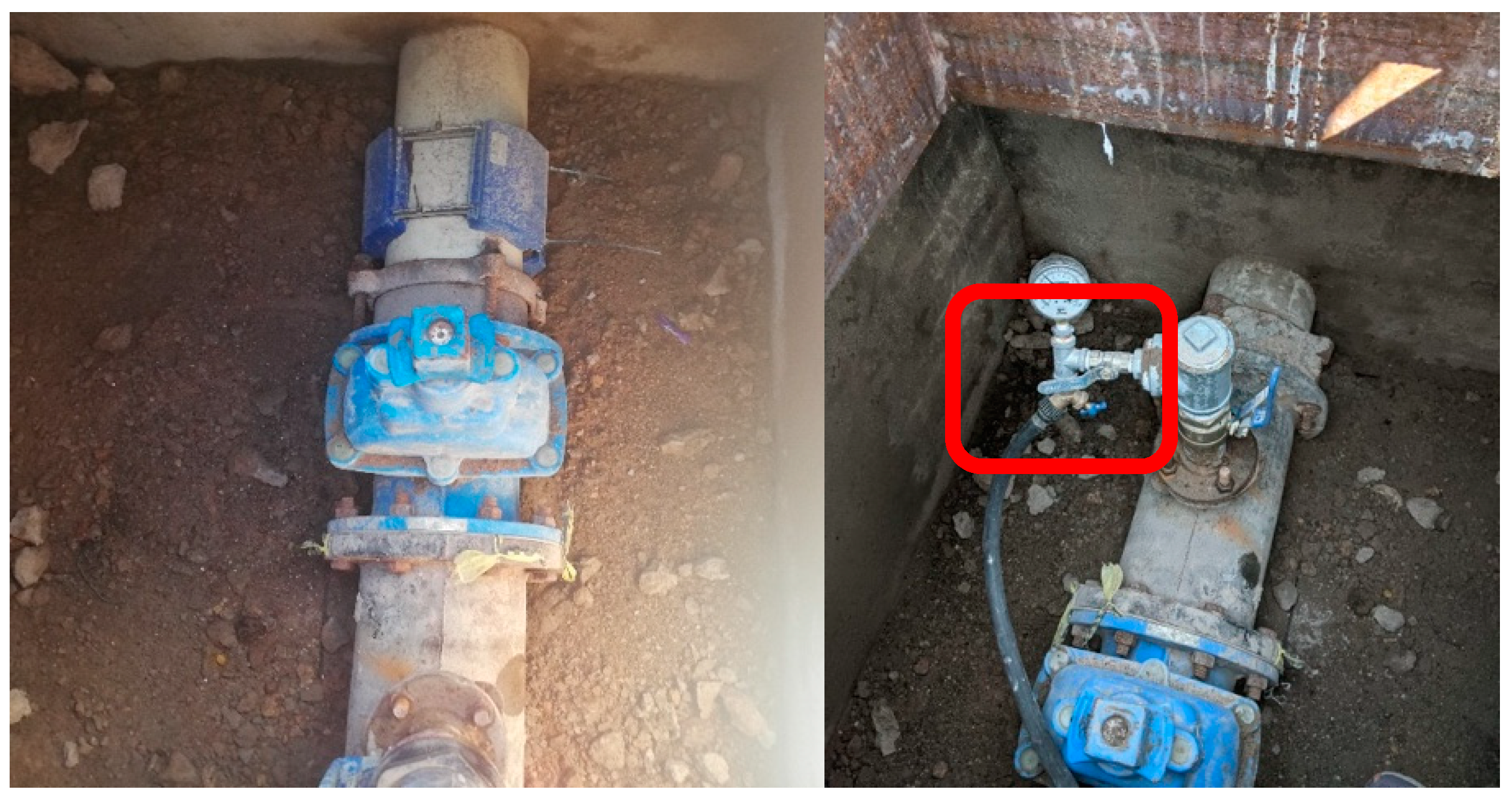
  • FF121 AM System (Fluid Force). This system comprised four rectangular magnets (162 mm × 150 mm × 55 mm), encased in plastic covers and arranged around an 8-inch PVC pipe. Their north poles faced the center, creating mutual repulsion. As shown in Figure 1, this system—installed by JMAS in Quinta Versalles—featured direct surface contact between the magnets and the pipe exterior, although the magnets did not interact with the water;
  • FF5 System (Fluid Force). This system featured two radially magnetized, arc-shaped Fluid Force FF5 magnets installed around a 1-inch PVC pipe, with their north poles oriented toward the center. Located in the CIMAV magnetism laboratory, it regulated water flow via a ball valve, allowing water to pass through the magnetic field before collection. According to the manufacturer, these magnets are designed for iron pipes requiring a strong magnetic signal and are commonly used in domestic water networks and industrial machinery. Each magnet measures 106 mm × 68 mm × 27 mm;
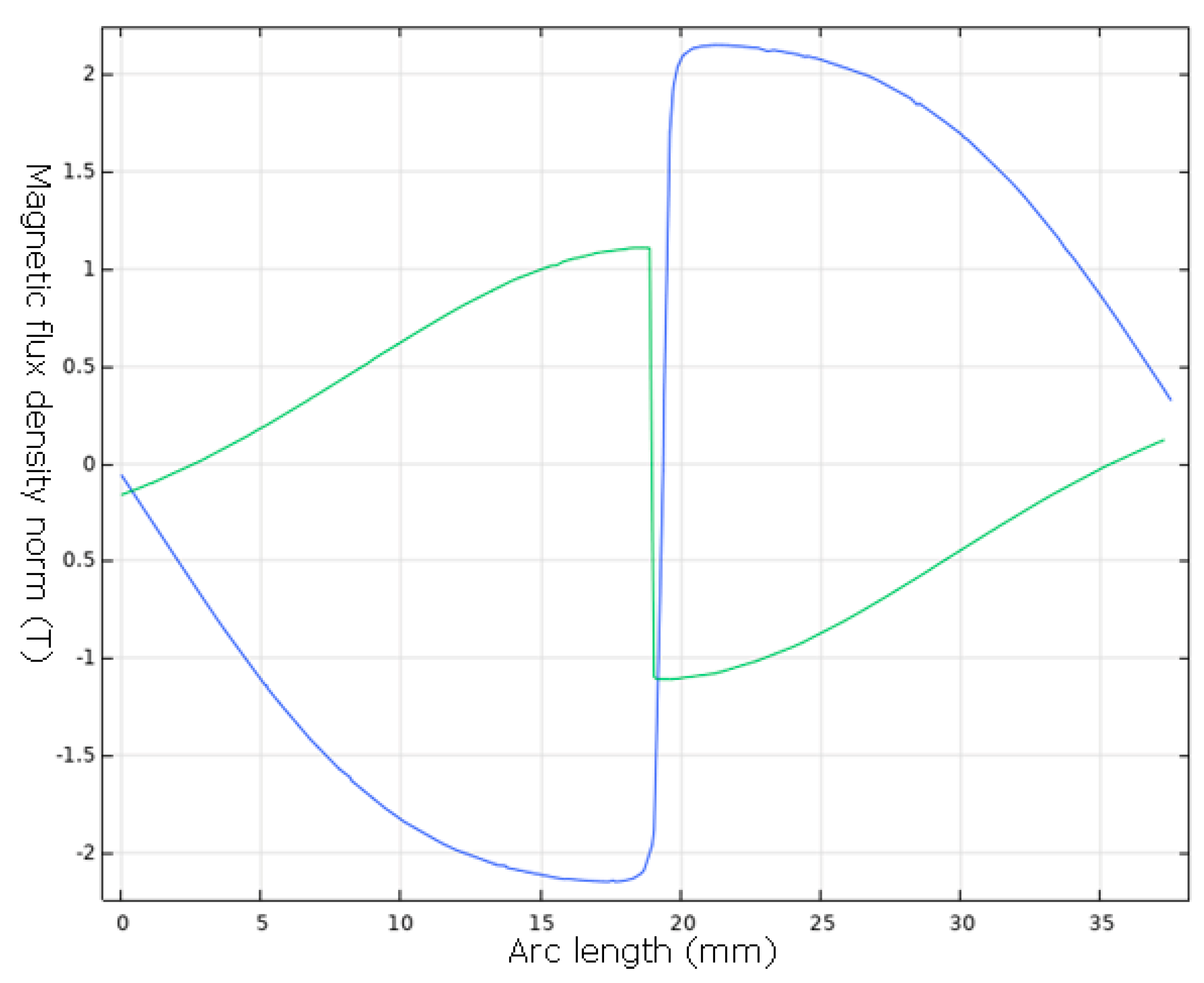
  • IH System (Magnetic Solutions). A 1-Tesla Halbach cylinder from Magnetic Solutions was used for laboratory-scale studies at the CIMAV magnetism laboratory. This system produced a uniform radial magnetic field within a 1-inch central hole, with a field gradient at both the inlet and outlet. A 1-inch PVC pipe was positioned over the cylinder, allowing water to flow through the magnetic field without direct contact. Opening the red valve enabled water to pass through, undergo magnetization, and be collected.
At Quinta Versalles, MW and NMW samples were collected in 1 L beakers, placed on open-air racks, and allowed to evaporate naturally. At each sampling point, solid residues were retrieved and analyzed independently. To monitor the evolution of calcium carbonate precipitation over time, MW was sampled at 13 time intervals—0 h, 12 h, 24 h, 36 h, 48 h, 72 h, 96 h, 120 h, 144 h, 168 h, 192 h, 216 h, and 240 h after exposure to magnetic treatment. The experiment was conducted across three distinct magnetization systems. All measurements were performed in triplicate to ensure reproducibility.
The analyses included the following:
  • Physicochemical—Electrical conductivity and chemical composition (Al, Ba, Ca, Cu, Fe, K, Mg, Mn, Mo, Na, Si, Sr, Zn) were assessed via inductively coupled plasma (ICP) spectroscopy, and pH via an Orion Versa Star meter (Thermo Scientific, Waltham, MA, USA);
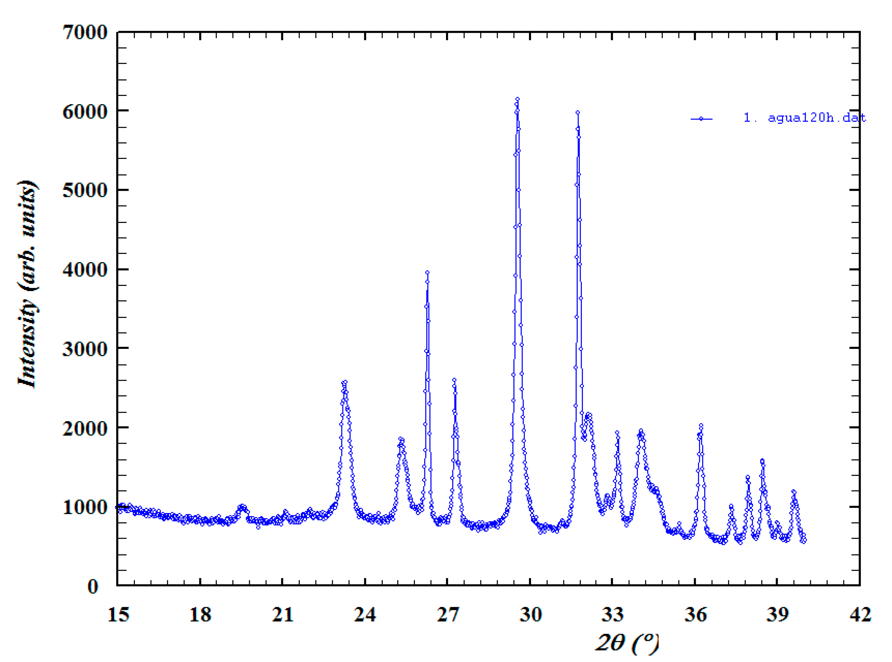
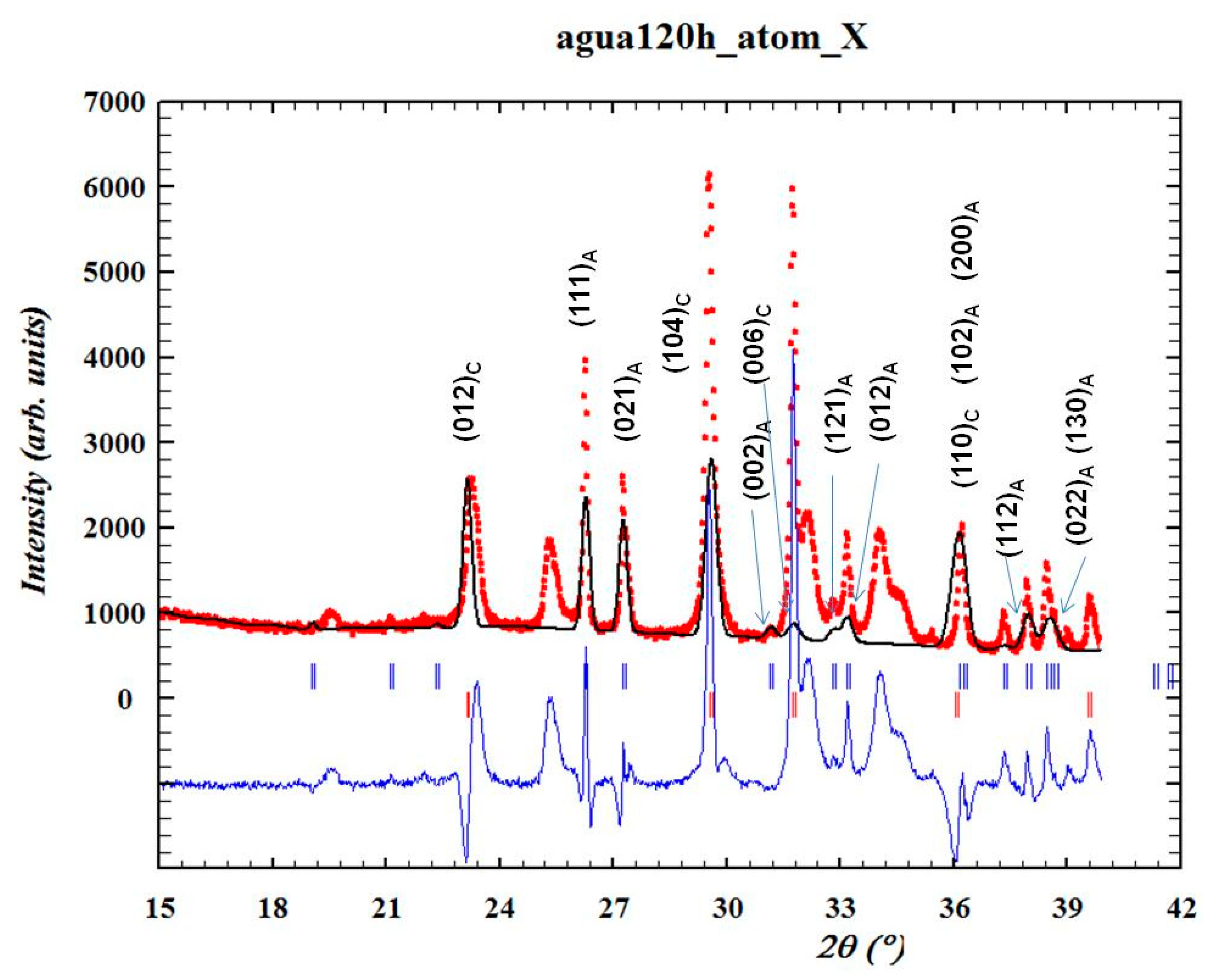
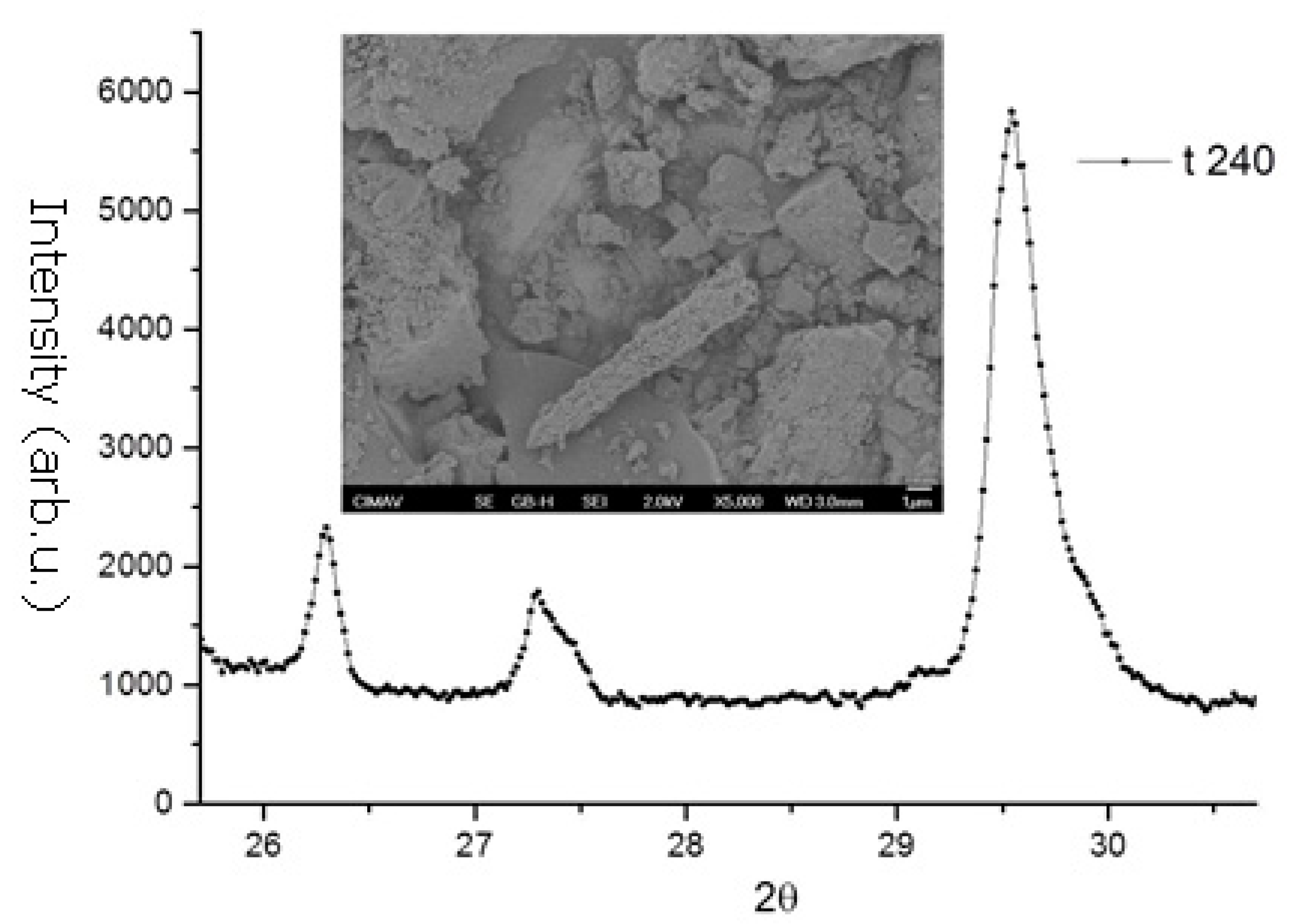
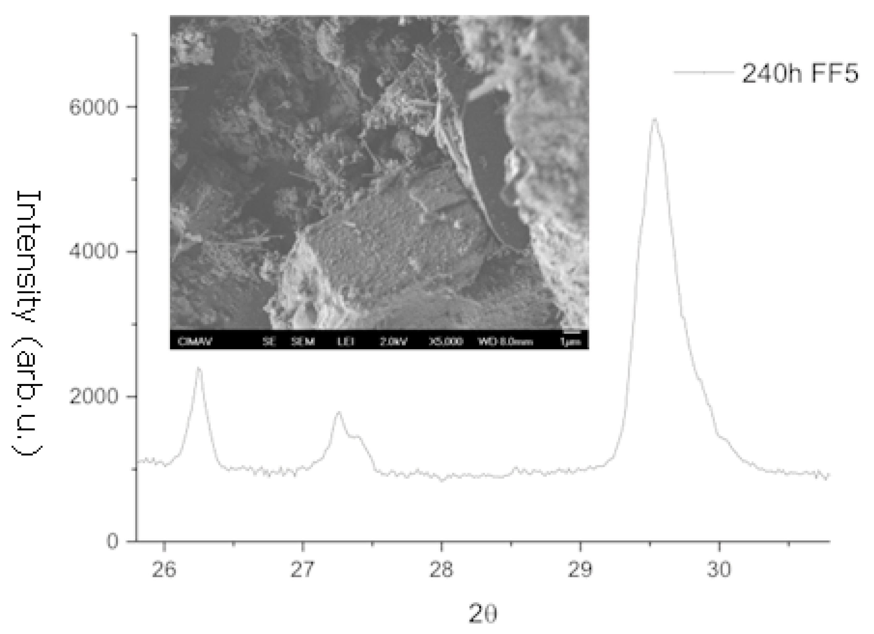
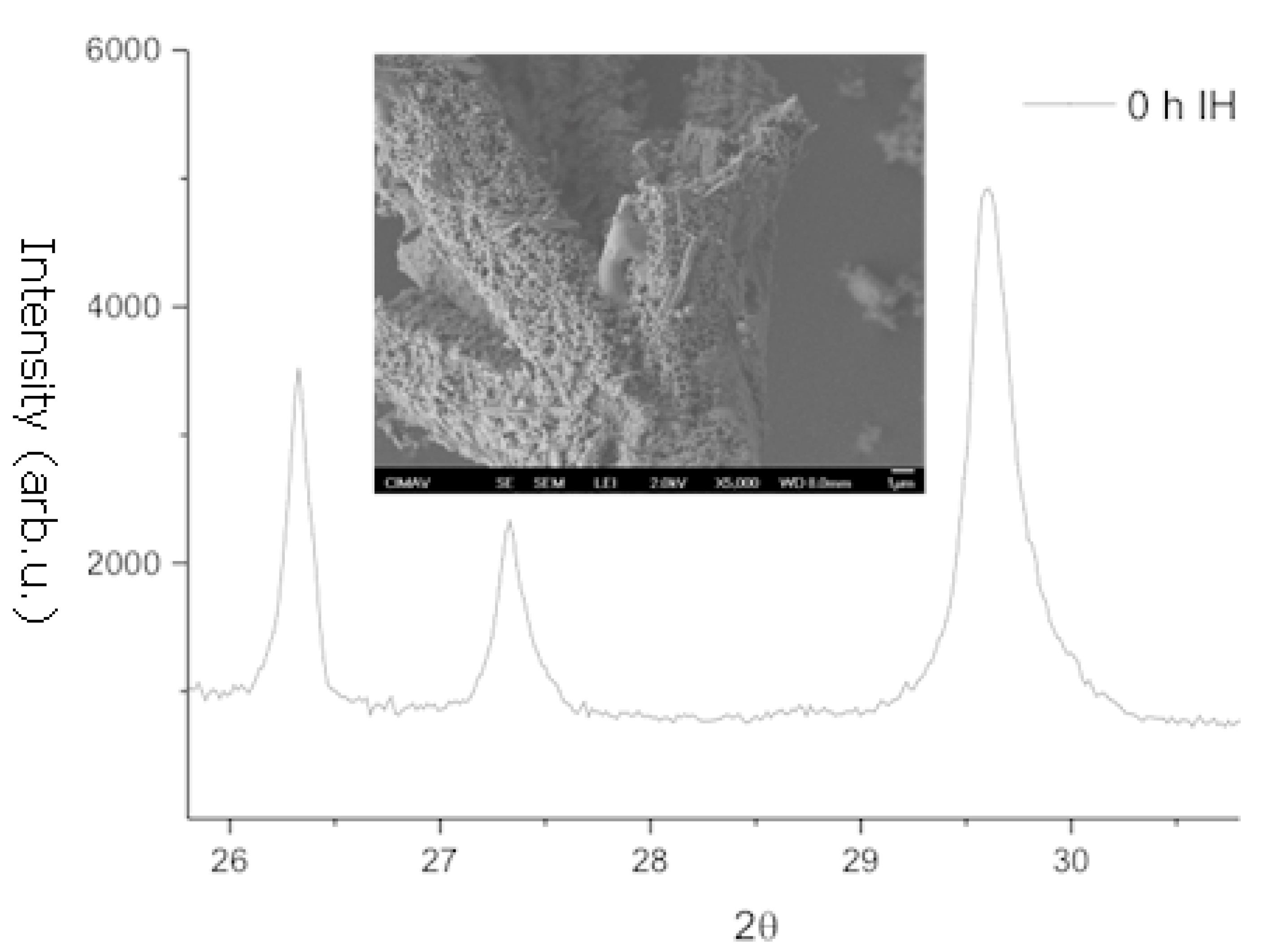
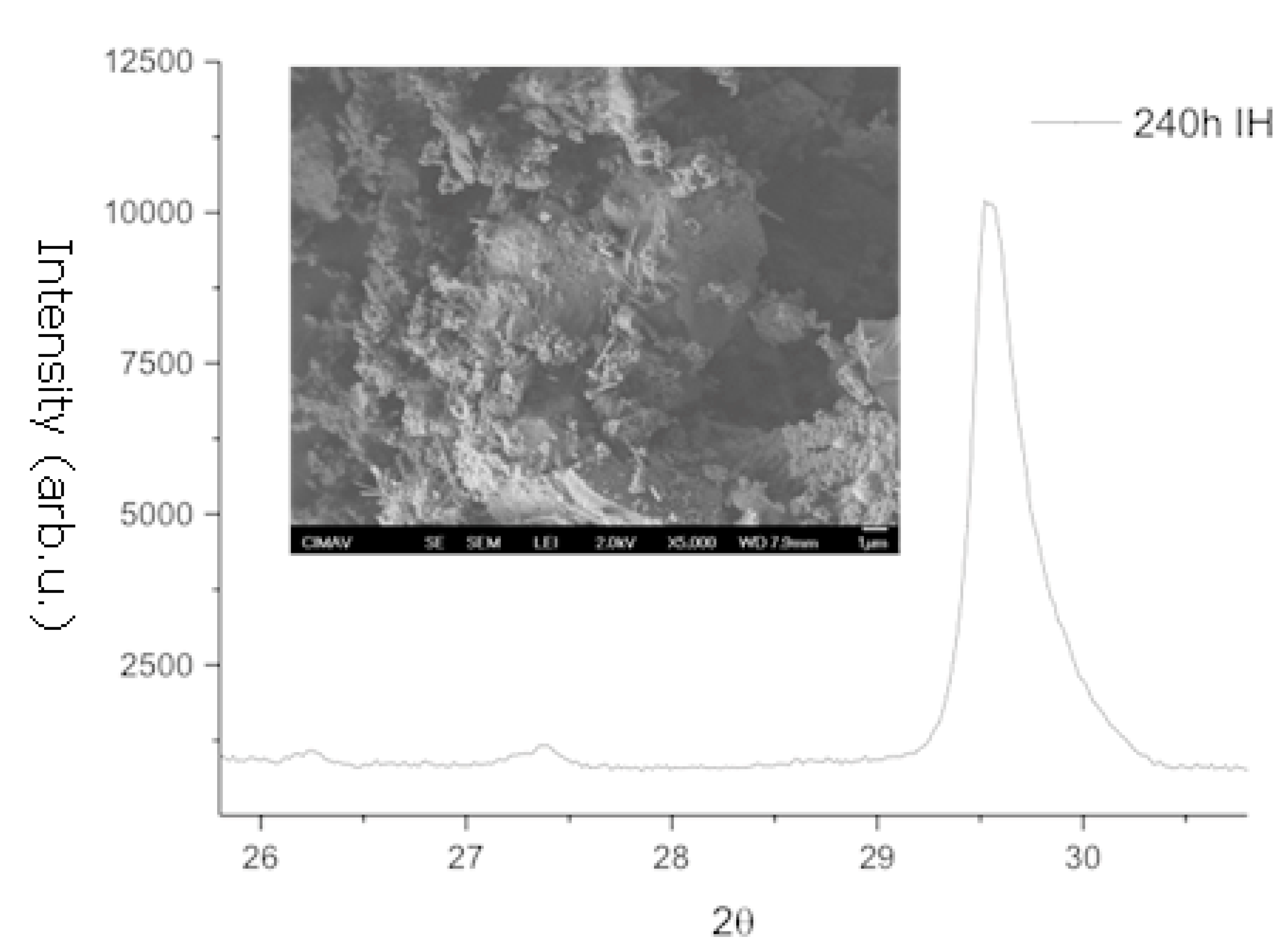
  • Structural analysis—X-ray diffraction (XRD) using a Bruker D8 Discover diffractometer using Cu-Kα radiation (Billerica, MA, USA). The crystallographic evolution of calcite and aragonite was assessed using the Rietveld refinement method in FullProf. The aragonite fraction (A) was determined using
    A = I 111 + I 021 I 111 + I 021 + I 104
    where I104, I111, and I021 correspond to calcite and aragonite XRD peak intensities.
Morphological analysis. Scanning electron microscopy (SEM) (JEOL FESEM JSM-7401F, Tokyo, Japan) was employed to examine the surface morphology and characteristics of the precipitates.
XRD and SEM were used to monitor the transformation of calcium carbonate polymorphs over time, with periodic evaporation and residue analysis to determine the relative proportions of calcite and aragonite.

3. Results

Table 1 presents the chemical composition (mg/L) of NMW from Quinta Versalles and MW treated with the FF121. The values shown represent the averages of measurements taken over the experimental period (0–240 h), confirming the stability and reproducibility of the ion concentrations. The water is predominantly composed of sodium (80 mg/L), calcium (49 mg/L), and silicon (21 mg/L). These elements contribute to the formation of carbonate, chloride, and silicate phases, which are detected as diffraction peaks via XRD analyses. In particular, the study focuses on the calcium carbonate content in the crystalline forms of calcite and aragonite. Calcite is the more thermodynamically stable phase, whereas an increased aragonite-to-calcite ratio is associated with reduced scaling in pipelines.
Table 2 compares the pH and conductivity of NMW, MW treated with the FF121 at Quinta Versalles, laboratory-magnetized water using the FF5, and laboratory-magnetized water treated with IH from Magnetic Solutions. The results indicate that all samples exhibit a slightly basic pH (>7), with the highest pH observed in NMW. Since pH significantly influences calcium carbonate precipitation, minor variations affect the formation of calcite and aragonite.

3.1. X-Ray Diffraction and Scanning Electron Microscopy

A representative XRD pattern is shown in Figure 2, corresponding to MW after 120 h of magnetization at Quinta Versalles. In Figure 3, the same XRD pattern is presented with an approximate refinement using the Rietveld method. The refinement includes only the diffraction peaks of calcite and aragonite, while additional peaks corresponding to unidentified phases are also visible.
The diffraction peaks at (104) for calcite and (111) and (021) for aragonite are clearly observed in Figure 3, and their temporal evolutions were monitored following thermal treatment. Consequently, the diffraction patterns are displayed within the angular range relevant to these peaks, although measurements were conducted over a broader 2θ range.
The temporal evolutions of XRD patterns and microstructural changes in MW treated with FF121 magnets at Quinta Versalles are illustrated in Figure 4 (0 h) and Figure 5 (240 h). Each figure highlights the relevant XRD pattern section and includes an SEM image of the precipitates. For reference, calcite precipitates display an equiaxed morphology, while aragonite forms acicular structures.
The analysis of all samples collected at each time interval confirms the presence of calcium carbonate in both calcite and aragonite phases. However, the relative proportions of these polymorphs do not follow a consistent trend over time after magnetic treatment. Consequently, no definitive effect can be attributed to the applied magnetic field. Similarly, the evolution of XRD patterns and microstructural changes in the MW magnetically treated in the laboratory with AM FF5 magnets are shown in Figure 6 (0 h) and Figure 7 (240 h).
The results across all time intervals consistently confirm the presence of calcium carbonate in both calcite and aragonite phases. However, the relative proportions of these polymorphs do not follow a discernible trend over time after magnetic field treatment. Consequently, no conclusive effect can be ascribed to the applied magnetic field.
The temporal evolutions of XRD patterns and microstructural changes in MW magnetically treated in the laboratory with the IH System magnet are presented Figure 8 (0 h) and Figure 9 (240 h).
The results reaffirm the presence of calcium carbonate in both calcite and aragonite phases. However, the measured proportions of these polymorphs do not display a consistent trend across the different time intervals following magnetic field treatment. Consequently, no definitive effect can be attributed to the applied magnetic field.

3.2. Simulations

The simulation of magnetic fields and their gradients for the FF121 magnet system, applied at Quinta Versalles in an 8-inch pipeline, was performed using the finite element method in COMSOL Multiphysics.
The results show that the system consists of four arc-shaped magnets (depicted in blue), radially magnetized and positioned at the top, bottom, left, and right. Since all magnets have their north poles oriented toward the center, they generate a repulsive force among them. The analysis of the magnetic field gradient components (B-field) along the z- and y-axes reveals distinct spatial variations.
Figure 10 illustrates the force lines of the magnetic field (B), where the tangent at any given point indicates the local field direction. A higher concentration of force lines corresponds to regions of greater magnetic field intensity, whereas a sparse distribution of lines in the central region suggests a significantly weaker field. These results confirm that the magnetic field is non-uniform, exhibiting greater intensity at the periphery and decreasing toward the center.
Furthermore, the magnetic field (B) curves in Tesla, also presented in Figure 10, show that due to the system’s symmetry, the curves along the z- and y-axes overlap. The field intensity is highest at the periphery and progressively decreases toward the center, where it stabilizes and remains nearly constant within a specific region.
Figure 11 illustrates the derivatives of the magnetic field (B) gradient, which are relevant to the Coey criterion. The results indicate that, for this magnet configuration, the gradient remains zero over a substantial central region and increases toward the periphery with opposite signs. This finding suggests that, according to the Coey criterion, the magnetic field gradient is not conducive to significant effects within a large portion of the central region.
Figure 12 presents the COMSOL Multiphysics simulation results for the FF5 magnet system installed in a 1-inch laboratory pipeline, illustrating the magnetic field (B) force lines for this configuration. Unlike the previous case, where the force lines exhibited symmetry along the z- and y-axes, this configuration lacks such symmetry. Due to the north poles of both magnets being oriented toward the center, a repulsive interaction is generated, resulting in a B-field of zero at the center.
Additionally, Figure 12 shows the magnetic field (B) curves in Tesla. In contrast to the previous configuration, the curves are no longer identical along the z- and y-axes. The results indicate that the magnetic field intensity is highest at the periphery and gradually decreases toward the center.
Figure 13 illustrates the derivatives of the magnetic field (B) gradient, which are relevant to the Coey criterion. This magnet configuration exhibits a significantly higher B-field gradient compared to the previous arrangement. The gradient increases toward the center, where it abruptly crosses zero and reverses sign. Moreover, unlike the previous case, the gradients along the z- and y-axes are not identical.
According to the Coey criterion, which favors large magnetic field gradients, this magnet system demonstrates enhanced performance relative to the earlier configuration.

4. Discussion

The analysis confirms the presence of CaCO3 in both calcite and aragonite phases across all three types of MWT applied. However, the measured proportions of these polymorphs do not exhibit a systematic trend over time following magnetic field exposure. Consequently, no definitive effect can be attributed to MWT, aligning with previous studies [10,11,21] that have struggled to establish a direct mechanism linking magnetism to scale formation. The variability in reported outcomes across different experiments suggests that factors such as magnetic field configuration, water flow conditions, and treatment duration play a critical role in the observed effects [7,8].
One key factor influencing these results is the specific characteristics of the magnetic field. Finite element simulations indicate that the magnetic field gradient generated by the Quinta Versalles magnets is negligible over a significant portion of the pipe cross-section (Figure 10). According to the Coey criterion, magnetic field gradients are crucial in influencing mineral precipitation [26]. The absence of a substantial gradient in this setup may explain the lack of detectable effects on CaCO3 crystallization.
The arrangement of permanent magnets is a critical determinant of MWT efficiency, often more influential than magnetic field strength, water flow rate, or temperature [7,19]. For instance, U-shaped magnet configurations, which align both north and south poles in the same direction, generate stronger magnetic peaks than conventional setups. Studies have demonstrated that increasing both magnetic field intensity and flow rate enhances MWT efficiency, with improvements of up to 8.8% as flow rate increases [3,7]. The observed variations in CaCO3 polymorph formation under magnetic treatment support findings by Alimi et al. [10], suggesting that scale precipitation is more dependent on water chemistry than on pipe material composition.
Although this study did not observe a systematic change in the calcite-to-aragonite ratio over time, previous research has reported significant shifts in CaCO3 polymorph distribution under magnetic fields. For example, Tai et al. [19] documented a transformation where calcite decreased from 65% to 27%, while aragonite increased from 35% to 73% following magnetic exposure. However, these results were obtained under different experimental conditions and should not be directly extrapolated to this study. If MWT influences polymorph selection, its effects are likely highly dependent on treatment duration, magnetic field strength, and water composition. The impact of magnetic fields on scale formation has been associated with alterations in water’s physical and chemical properties [27]. Electromagnetic fields can modify the hydrogen bonding network in water, affecting its molecular structure and dipole moment. The Lorentz force generated by the field may realign water molecules and disrupt hydrogen bonding, leading to structural changes in water clusters. These effects could contribute to the transformation of CaCO3 polymorphs observed under magnetic treatment, suggesting a complex interplay between water structure and mineral precipitation [20].
SEM analysis further confirms morphological differences in scale deposits. The first extracted sample exhibited agglomerated particle formations primarily composed of oxygen, calcium, and carbon, with minor amounts of silicon, magnesium, aluminum, and iron. In contrast, the second extracted sample displayed an irregular morphology with compositional variations across different regions, where oxygen, sodium, aluminum, silicon, and iron were dominant. These findings suggest that the impurities or variations in water composition may also influence the crystallization process [7].
Additionally, CO2 and ionic species such as Na+ and Cl may play a role in calcite and aragonite formation. Pouget et al. [31] stated that CO2 evaporation under dynamic flow conditions can promote the kinetic formation of vaterite, an unstable intermediate phase of CaCO3, while dissolved Na+ and Cl facilitate calcite nucleation. It is also possible that magnetohydrodynamic forces induce internal stresses and distort the lattice structure of CaCO3 particles, affecting phase stability and polymorph selection [27]. While this study did not observe a significant reduction in overall scale formation, the detected morphological changes suggest that MWT could still offer benefits in scaling control by producing fewer adherent deposits, potentially improving long-term maintenance in distribution systems. Although the precise mechanism remains elusive, the results reinforce the complexity and context dependency of MWT effects. Importantly, the integration of finite element simulations with experimental observations highlights the role of magnetic field geometry in influencing crystallization behavior. These insights contribute to the broader understanding of how design-specific parameters affect treatment performance, while also pointing to the challenges of replicability and mechanistic clarity that future research must address.

5. Conclusions

This study shed light on the importance of magnetic field configuration in MWT applications, demonstrating that different magnet arrangements produce distinct effects on scale formation. Finite element simulations provided valuable insight into the spatial distribution of the magnetic field, highlighting the necessity for proper field alignment and gradient optimization to enhance treatment efficiency. Additionally, SEM and XRD analyses revealed subtle differences in scale morphology and composition, underlining the influence of water composition and impurity interactions in crystallization processes.
Although the calcite-to-aragonite ratio did not exhibit a systematic evolution, these findings contribute to the ongoing debate on MWT’s efficacy by emphasizing the complex interplay between magnetic forces, crystallization kinetics, and water composition. Future research should build on these results by further refining the standardization of experimental conditions to facilitate the real-time analysis of key variables over extended periods. Enhancing magnetic field configurations and integrating real-time monitoring techniques will be crucial for a deeper understanding of the underlying mechanisms. Moreover, long-term field studies in operational water distribution systems could provide essential insights into the practical applications of MWT for scaling control and infrastructure maintenance.

Author Contributions

D.S.: conceptualization, methodology, investigation, writing. E.H.-P.: conceptualization, editing. C.N.-G.: writing—review, editing. J.R.S.-N.: validation, visualization. All authors have read and agreed to the published version of the manuscript.

Funding

This research received no external funding.

Data Availability Statement

The data and materials used in this study are openly available and appropriately cited. The complete data and experimental information are available upon request. All data sources, including references and citations, are provided in the reference list and are accessible to the scientific community and interested readers.

Acknowledgments

The authors gratefully acknowledge the Chihuahua Municipal Water and Sanitation Board (JMAS Chihuahua) for its institutional support and strong commitment to fostering this research, aimed at analyzing and addressing the challenges associated with drinking water distribution. We also wish to thank INCOTEX, with special recognition to Architect Hugo Navarro, for his generous support and valuable contribution in providing the materials necessary for this study. Our sincere appreciation is extended to José Matutes and his team at the Center for Advanced Materials Research (CIMAV), whose collaboration was instrumental in developing the simulation and experimental framework. Their technical expertise, thoughtful guidance, and enriching discussions throughout the research process were essential to the successful execution and strengthening of this work. We also acknowledge the support of the Secretariat of Science, Humanities, Technology, and Innovation (Secretaría de Ciencia, Humanidades, Tecnología e Innovación, SECIHTI-México) through the project Estancia Posdoctoral Académica (3) 2022 and the scholarship No. 613286 awarded to David Sánchez. Finally, we are grateful to the anonymous reviewers for their constructive comments and valuable suggestions, which helped improve the quality of this manuscript.

Conflicts of Interest

The authors declare no conflicts of interest.

References

  1. Siva, T.; Muralidharan, S.; Sathiyanarayanan, S.; Manikandan, E.; Jayachandran, M. Enhanced Polymer Induced Precipitation of Polymorphous in Calcium Carbonate: Calcite Aragonite Vaterite Phases. J. Inorg. Organomet. Polym. Mater. 2017, 27, 770–778. [Google Scholar] [CrossRef]
  2. Antony, A.; How Low, J.; Gray, S.; EChildress, A.; Le-Clech, P.; Leslie, G. Scale formation and control in high pressure membrane water treatment systems: A review. J. Membr. Sci. 2011, 383, 1–16. [Google Scholar] [CrossRef]
  3. Wang, Y.; Wei, H.; Li, Z. Effect of magnetic field on the physical properties of water. Results Phys. 2018, 8, 262–267. [Google Scholar] [CrossRef]
  4. Su, M.; Han, J.; Li, Y.; Chen, J.; Zhao, Y.; Chadwick, K. Ultrasonic Crystallization of Calcium Carbonate in Presence of Seawater Ions. Desalination 2015, 369, 85–90. [Google Scholar] [CrossRef]
  5. Zarga, Y.; Ben Boubaker, H.; Ghaffour, N.; Elfil, H. Study of calcium carbonate and sulfate co-precipitation. Chem. Eng. Sci. 2013, 96, 33–41. [Google Scholar] [CrossRef]
  6. Younes, A.A.; El-Maghrabi, H.H.; Ali, H.R. Novel polyacrylamide-based solid scale inhibitor. J. Hazard. Mater. 2017, 334, 1–9. [Google Scholar] [CrossRef]
  7. Othman, A.; Sohaili, J.; Sumaiyyah Supian, N. A Review: Methodologies Review of Magnetic Water Treatment as Green Approach of Water Pipeline System. Pertanika J. Sci. Technol. 2019, 27, 218–296. [Google Scholar]
  8. ElMassalami, M.; Teixeira, M.S.; Elzubair, A. Investigating the Antiscale Magnetic Treatment Controversy: Insights from the Model Calcium Carbonate Scalant. Sci. Rep. 2025, 15, 3441. [Google Scholar] [CrossRef]
  9. Busch, K.W.; Busch, M.A.; Parker, D.H.; Darling, R.E.; McAtee, J.L. Studies of a water treatment device that uses magnetic fields. Corrosion 1986, 42, 211–221. [Google Scholar] [CrossRef]
  10. Alimi, F.; Tlili, M.M.; Ben Amor, M.; Maurin, G.; Gabrielli, C. Effect of magnetic water treatment on calcium carbonate precipitation: Influence of the pipe material. Chem. Eng. Process. Process. Intensif. 2009, 48, 1327–1332. [Google Scholar] [CrossRef]
  11. Baker, J.S.; Judd, S.J. Magnetic amelioration of scale formation. Water Res. 1996, 30, 247–260. [Google Scholar] [CrossRef]
  12. Ali, A. Effect of Magnetic Treatment on Temporary Hardness of Groundwater. Asian J. Chem. 2019, 31, 1017. [Google Scholar]
  13. Dalas, E.; Koutsoukos, P.G. The effect of magnetic fields on calcium carbonate scale formation. J. Cryst. Growth 1989, 96, 802–806. [Google Scholar] [CrossRef]
  14. Alabi, A.; Chiesa, M.; Garlisi, C.; Palmisano, G. Advances in anti-scale magnetic water treatment. Environ. Sci. Water Res. Technol. 2015, 1, 408–425. [Google Scholar] [CrossRef]
  15. Al Helal, A.; Soames, A.; Gubner, R.; Iglauer, S.; Barifcani, A. Influence of magnetic fields on calcium carbonate scaling in aqueous solutions at 150 °C and 1 bar. J. Colloid Interface Sci. 2018, 509, 472–484. [Google Scholar] [CrossRef]
  16. Lin, L.; Jiang, W.; Xu, X.; Xu, P. A critical review of the application of electromagnetic fields for scaling control in water systems: Mechanisms, characterization, and operation. NPJ Clean Water 2020, 3, 25. [Google Scholar] [CrossRef]
  17. Chung, A.; Sheng, H.; Ling, J. Magnetic Induction on pH, Oxidation-Reduction Potential, Conductivity and Dissolved Oxygen Level of Water and Its Properties: A State-of-the-Art Review. In Sustainable Groundwater and Environment: Challenges and Solutions; Li, P., He, X., Wu, J., Elumalai, V., Eds.; Springer: Cham, Switzerland, 2025; pp. 279–309. [Google Scholar]
  18. Bian, Y.; Li, S.; Luo, H.; Lv, L.; Zan, S.; Ren, B.; Zhu, G. Magnetic Metal–Organic Framework Enhanced Inorganic Coagulation for Water Purification. Water 2023, 15, 3391. [Google Scholar] [CrossRef]
  19. Tai, Y.C.; Wu, C.K.; Chang, M.C. Effects of magnetic field on the crystallization of CaCO3 using permanent magnets. Chem. Eng. Sci. 2008, 63, 5606–5612. [Google Scholar] [CrossRef]
  20. Liu, C.Z.; Lin, C.H.; Yeh, M.S.; Chao, Y.M.; Shen, P. Surface Modification and Planar Defects of Calcium Carbonates by Magnetic Water Treatment. Nanoscale Res. Lett. 2010, 5, 1982–1991. [Google Scholar] [CrossRef]
  21. Piyadasa, C.; Yeager, T.R.; Gray, S.R.; Stewart, M.B.; Ridgway, H.F.; Pelekani, C.; Orbell, J.D. The influence of electromagnetic fields from two commercially available water-treatment devices on calcium carbonate precipitation. Environ. Sci. Water Res. Technol. 2017, 3, 566–572. [Google Scholar] [CrossRef]
  22. Karar, A.; Henni, A.; Namoune, F.; Rosei, F. Inhibition of nucleation and crystal growth of calcium carbonate in hard waters using Paronychia arabica in an arid desert region. Water Environ. J. 2020, 34, 979–987. [Google Scholar] [CrossRef]
  23. Martínez, S.; Boluda, N. Review of Techniques to Reduce and Prevent Carbonate Scale. Prospecting in Water Treatment by Magnetism and Electromagnetism. Water 2021, 13, 2365. [Google Scholar] [CrossRef]
  24. Latva, M.; Inkinen, J.; Rämö, J.; Kaunisto, T.; Mäkinen, R.; Ahonen, M.; Matilainen, J.; Pehkonen, S. Studies on the magnetic water treatment in new pilot scale drinking water system and in old existing real-life water system. J. Water Process. Eng. 2016, 9, 215–224. [Google Scholar] [CrossRef]
  25. Silva, I.B.; Neto, J.C.Q.; Petri, D.F. The effect of magnetic field on ion hydration and sulfate scale. Colloids Surf. A Physicochem. Eng. Asp. 2015, 465, 175–183. [Google Scholar] [CrossRef]
  26. Coey, J.M.D.; Parkin, S.S.P. Handbook of Magnetism and Magnetic Materials; Springer Nature Link: Cham, Switzerland, 2020. [Google Scholar]
  27. Mghaiouini, R.; Benzbiria, N.; Belghiti, M.; Belghiti, H.; Monkade, M.; El Bouari, A. Optical properties of water under the action of the electromagnetic field in the infrared spectrum. Mater. Today Proc. 2020, 30, 1046–1051. [Google Scholar] [CrossRef]
  28. Alimi, F.; Tlili, M.; Ben Amor, M.; Gabrielli, C.; Maurin, G. Influence of magnetic field on calcium carbonate precipitation. Desalination 2006, 206, 163–168. [Google Scholar] [CrossRef]
  29. Kozic, V.; Krope, J.; Lipus, L.C.; Ticar, I. Magnetic field analysis on electromagnetic water treatment device. Hung. J. Ind. Chem. Veszprém 2006, 34, 51–54. [Google Scholar]
  30. Higashitani, K.; Kage, A.; Katamura, S.; Imai, K.; Hatade, S. Effects of a Magnetic Field on the Formation of CaCO3 Particles. J. Colloid Interface Sci. 1993, 156, 90–95. [Google Scholar] [CrossRef]
  31. Pouget, E.M.; Bomans, P.H.H.; Goos, J.A.C.M.; Frederik, P.M.; de With, G.; Sommerdijk, N.A.J.M. The initial stages of template-controlled CaCO3 formation revealed by Cryo-TEM. Science 2009, 323, 1455–1458. [Google Scholar] [CrossRef]
  32. INEGI. INEGI. 2020. Available online: https://www.inegi.org.mx/programas/ccpv/2020/default.html#Datos_abiertos (accessed on 28 December 2023).
Figure 1. Water magnetization system (FF121 AM System) installed by JMAS in Quinta Versalles.
Water 17 01265 g001
Figure 2. XRD pattern of Quinta Versalles water measured 120 h after exposure to the magnetic field generated by the FF121 system.
Water 17 01265 g002
Figure 3. Rietveld refinement of the XRD pattern of Quinta Versalles water (FF121 System) measured 120 h after magnetic field. Peaks for aragonite and calcite are identified, with additional unidentified peaks. Aragonite formation is tracked via the (111)A and (012)A peaks at 2θ = 26.25° and 27.24°, while calcite is monitored through the (104)C peak at 2θ = 29.57°.
Water 17 01265 g003
Figure 4. Magnified diffraction pattern showing aragonite (111)A, (012)A, and calcite (104)C peaks, alongside an SEM micrograph of the microstructure. Data correspond to Quinta Versalles water (FF121 System) immediately (0 h) after magnetic field exposure.
Water 17 01265 g004
Figure 5. Magnified diffraction pattern showing aragonite (111)A, (012)A, and calcite (104)C peaks, alongside an SEM micrograph of the microstructure. Data correspond to Quinta Versalles water (FF121 System) at 240 h post-magnetic field exposure.
Water 17 01265 g005
Figure 6. Magnified diffraction pattern highlighting aragonite (111)A, (012)A, and calcite (104)C peaks, alongside an SEM micrograph of the microstructure. Data correspond to Quinta Versalles water, magnetized in the laboratory with Fluid Force FF5 magnets, immediately (0 h) after exposure.
Water 17 01265 g006
Figure 7. Magnified diffraction pattern showing aragonite (111)A, (012)A, and calcite (104)C peaks, along with an SEM micrograph of the microstructure. Data correspond to Quinta Versalles water magnetized in the laboratory with Fluid Force FF5 magnets, 240 h after exposure.
Water 17 01265 g007
Figure 8. Magnified diffraction pattern highlighting aragonite (111)A, (012)A, and calcite (104)C peaks, alongside an SEM micrograph of the microstructure. Data correspond to Quinta Versalles water magnetized in the laboratory with a 1T Halbach cylinder IH System, immediately (0 h) after exposure.
Water 17 01265 g008
Figure 9. Magnified diffraction pattern showing aragonite (111)A, (012)A, and calcite (104)C peaks, along with an SEM micrograph of the microstructure. Data correspond to Quinta Versalles water magnetized in the laboratory with a 1T Halbach cylinder IH System, 240 h after exposure.
Water 17 01265 g009
Figure 10. Simulation of magnetic field force lines for the four-magnet system surrounding the pipe at Quinta Versalles (FF121 System), illustrating field cancellation at the center. Magnetic field (B) curves in Tesla along the y- and z-axes exhibit identical behaviors due to system symmetry.
Water 17 01265 g010
Figure 11. Magnetic field gradient (B) curves in Tesla along the y-axis (left-to-right magnet) and z-axis (bottom-to-top magnet). Both curves are identical due to system symmetry. This configuration corresponds to the four-magnet system surrounding the pipe at Quinta Versalles (FF121 System).
Water 17 01265 g011
Figure 12. Simulation of magnetic field force lines for the two-magnet system surrounding the 1-inch pipe in the laboratory (FF5 System), showing field cancellation at the center. Magnetic field (B) curves in Tesla along the y-axis (left-to-right magnet) and z-axis demonstrate the system’s magnetic distribution.
Water 17 01265 g012
Figure 13. Magnetic field gradient (B) curves in Tesla along the y-axis (left to right magnet) and the z-axis (bottom to top). This configuration corresponds to the two-magnet system surrounding the 1-inch pipe installed in the laboratory (AM FF5 System).
Water 17 01265 g013
Table 1. Chemical composition of MW 1 and NMW 2.
ElementMW
(mg/L)
Element
(mg/L)
Al0.020.014
Ba0.030.031
Ca49.18749.031
CuN.D.N.D.
FeN.D.N.D.
K2.2372.277
Mg5.685.721
MnN.D.N.D.
MoN.D.N.D.
Na81.24280.664
Si20.65120.477
Sr0.4470.477
Zn0.0080.034
Notes: 1 MW, magnetic water. 2 NMW, non-magnetic water.
Table 2. pH and conductivity measurement.
MeasurementNMW 2MW FF121 1MW FF5MW IH
pH8.7998.3528.2148.314
Conductivity (µS/cm)585583585596
Notes: 1 MW, magnetic water. 2 NMW, non-magnetic water.
Disclaimer/Publisher’s Note: The statements, opinions and data contained in all publications are solely those of the individual author(s) and contributor(s) and not of MDPI and/or the editor(s). MDPI and/or the editor(s) disclaim responsibility for any injury to people or property resulting from any ideas, methods, instructions or products referred to in the content.

