Article

Discharge Efficiency of an Innovative Composite Piano Key Weir

1
Chinese-German Institute of Engineering, Zhejiang University of Science and Technology, Hangzhou 310023, China
2
Hydraulic Engineering Section, Helmut-Schmidt-University—University of the Federal Armed Forces Hamburg, 22043 Hamburg, Germany
*
Author to whom correspondence should be addressed.
Water 2025, 17(7), 921; https://doi.org/10.3390/w17070921
Submission received: 10 February 2025 / Revised: 14 March 2025 / Accepted: 18 March 2025 / Published: 21 March 2025
(This article belongs to the Section Hydraulics and Hydrodynamics)

Abstract

:
Climate-change-induced increases in extreme rainfall events necessitate the enhancement of discharge capacity in aging dam infrastructures. Piano Key Weirs (PKWs), with their compact footprint and efficient discharge performance, present a promising option for improving the discharge efficiency of existing spillways. This study introduces an innovative composite Piano Key Weir (CPKW), which integrates both rectangular and trapezoidal layouts. Numerical simulations were performed to systematically compare the flow field and discharge performance between conventional trapezoidal PKW and composite configurations. Results show that the composite structure significantly improves the discharge capacity of the reference trapezoidal model by up to 16%. This enhancement is primarily attributed to the extended crest length and reduced local submergence, resulting in a more efficient discharge distribution. For the specific composite configurations studied, the optimal key width ratio that effectively balances the inflow efficiency and the adverse effects of nappe interference is found to range between 0.89 and 1.01. Additionally, a relative upstream head of 0.2–0.3 is identified as a critical threshold, beyond which the intense local submergence starts to affect the downstream trapezoidal side-wall section, limiting the contribution of the entire side wall to the total discharge and resulting in decreased overall efficiency.

1. Introduction

The impact of climate change is becoming increasingly evident, as reflected in the rising frequency and intensity of extreme rainfall events [1,2,3,4]. These phenomena present unprecedented challenges to existing dam infrastructures whose original desgins were based on historical hydraulic data. Contemporary assessments reveal critical safety concerns regarding these structures’ capacity to accommodate amplified discharge requirements, highlighting an urgent need for innovative engineering interventions [5,6]. Among emerging solutions, the implementation of piano key weirs (PKWs) has gained growing attention. PKWs represent an advanced type of non-linear weir characterized by a series of “key units” that significantly enhance discharge capacity. Notably, PKWs offer the advantage of enhancing hydraulic performance without necessitating extensive modifications to the existing structure, making them a highly attractive option for the rehabilitation of aging dams [7,8,9,10,11,12].
To date, substantial research efforts have been devoted to understanding PKW hydraulics and to optimizing their performance. Parametric studies have established that optimizing geometric parameters can substantially improve the discharge capacity of a PKW, with the magnification ratio ( L / W ), weir height, inlet/outlet key width ratio, and overhang length being identified as the most important parameters that have significant influence on the final discharge performance [13,14,15,16,17,18]. In addition, Shen and Oertel [19] explored the impact of different PKW crest shapes on PKW flow dynamics, scale effects, and energy dissipation, reporting that the half-round crest shape exhibited the highest discharge efficiency, while the flat crest offered superior energy dissipation efficiency. Moreover, Cicero et al. [20] and Kumar et al. [21] have highlighted that trapezoidal plan form geometries are able to achieve higher discharge efficiency per unit crest length compared to traditional rectangular PKWs.
Overall, prior studies have put forward various suggestions for optimizing the discharge performance of PKWs. However, despite these advances, current research remains predominantly focused on conventional rectangular and trapezoidal PKWs. Yang et al. [22] have proposed a PKW with an elliptical crest design, which produces increased total crest length and improved discharge efficiency. Shen and Oertel [23] conducted a preliminary investigation into composite piano key weirs (CPKWs), demonstrating that combining both rectangular and trapezoidal planforms can further enhance the discharge efficiency of conventional PKWs. Nonetheless, the previously proposed CPKW design revealed a critical limitation: while positioning the rectangular configuration upstream alleviates localized interference effects under low-head conditions, this arrangement inherently narrows the inlet cross-sectional width compared to trapezoidal configurations, thereby compromising inlet discharge efficiency. To address this constraint, the present study introduces an optimized composite configuration that retains the efficient inflow cross-section of the conventional trapezoidal PKW (TPKW) by incorporating the rectangular form through an upward-extending parapet wall structure. This modification is achieved by initially truncating a portion of the original TPKW’s height (Figure 1), thereby retaining the trapezoidal configuration’s advantageous inflow cross-sectional area. The proposed design maintains the total structural height of the weir while strategically merging the hydraulic benefits of both planforms. To assess whether such a design further optimizes discharge performance, a systematic comparison of the flow characteristics between the proposed CPKW and the conventional TPKW is conducted in the present study. In addition, varying key width ratios are also tested for CPKWs in order to identify the optimum range for performance.

2. Model Setup

2.1. Investigated Model Configurations

Within this study, two different types of PKWs are investigated: (1) a conventional TPKW as the reference model and (2) a CPKW with varying key width ratios. The reference TPKW configuration was adopted from the experiments of Shen and Oertel [19], in which the detailed experimental setup and applied measurement techniques are described. The specific geometric parameters of all seven tested weir configurations are summarized in Table 1. For all models investigated herein, the weir height (P), weir length (B), weir width (W) and the side-wall angle ( α ) were kept constant for a better comparison. Corresponding geometries for CPKWs are additionally demonstrated in Figure 2. Since the geometry of a PKW is defined by a multitude of parameters, the present study adopts the nomenclature proposed by Pralong et al. [24] for consistency and clarity. Nonetheless, since the CPKW configuration is more complex than conventional PKWs, additional parameters have been included, such as W i , u —inlet key width upstream, W i , d —inlet key width downstream, W o , u —outlet key width upstream, W o , d —outlet key width downstream, S W i —trapezoidal side-wall length, and S W o —rectangular side-wall length.

2.2. Numerical Model

A total of 49 simulations were performed in this study utilizing the commercially available computational fluid dynamics (CFDs) solver FLOW-3D, which calculates the Reynolds-averaged Navier–Stokes equations using the finite-volume method. A workstation that has an AMD EPYC 7532 32-core 2.4 GHz processor with 64 GB RAM was used. Due to the geometric symmetry, each configuration was simulated in one half unit with symmetric lateral boundary conditions to reduce the calculation time. As confirmed by Pfister et al. [25] and Safarzadeh and Noroozi [26], the number of units does not affect the unit hydraulic behavior of a PKW in terms of head–discharge relationships. The discharge coefficients derived from one half unit are therefore representative of the entire multi-unit configuration. The numerical domain comprises three mesh regions: (1) an upstream region; (2) a weir region, in which the PKW configuration is located; and (3) a grid refinement region at the weir crest area. Utilizing the grid convergence index (GCI) method proposed by Celik et al. [27], a grid independence test was performed for three different initial cell sizes with a grid refinement factor F s 1.25 . Table 2 presents an exemplary calculation of the GCI index. Based on the results, a 20 mm grid was used for the upstream region, while the main region featured a grid size of 10 mm. Within the third region at the weir crest area, a refined grid of 5 mm was used to improve the crest and top plane resolution. Similar as employed in [28,29,30], the model configuration was captured via the fractional area/volume obstacle representation (FAVOR) method, with the free surface being detected using a volume of fluid (VOF) function. The RNG model was employed to calculate the turbulence, while the second-order monotonicity preserving method was used to compute the momentum advection. The inflow boundary condition was defined by stagnation pressure corresponding to the total hydraulic head. The outlet condition was set to a static pressure condition with 0 pressure corresponding to a free outlet. The top boundary was configured as a pressure boundary with zero gauge pressure, while the bottom boundary was set as a wall. All numerical results were derived at steady-state conditions.

2.3. Verification of Numerical Results

To validate the numerical results, Figure 3 includes the experimental results of the reference TPKW configuration reported by Shen and Oertel [19] and compares the resulting discharge coefficients ( C d L ) derived from numerical simulation and laboratory experiments. The C d L values represent the overall discharge efficiency of a PKW per unit crest length and can be computed using Equation (1):
C d L = 3 · Q 2 · L · 2 g · H t 3 / 2
where Q = discharge; C d L = discharge coefficient related to total crest center-line length, representing the discharge capacity per unit weir length; g = acceleration due to gravity; L = total crest center-line length; W = total weir width; and H t = total upstream head relative to weir crest.
The results demonstrate a high degree of agreement between the numerically and experimentally derived C d L values (Equation (1)), with the maximum relative deviation remaining below 5%. This minimal discrepancy indicates that the employed numerical settings are capable of accurately capturing the discharge behavior of a PKW.

3. Results and Discussions

3.1. Overall Discharge Performance of CPKWs

Figure 4 presents a comparison of the discharge coefficients ( C d W ) for composite PKW configurations with varying key width ratios relative to the reference trapezoidal PKW model. Since the total crest lengths of the TPKW and CPKW configurations differ under the same total width, the discharge coefficient C d W was employed to facilitate a more accurate comparison. This coefficient represents the overall discharge capacity per unit weir width and is calculated using Equation (2) as follows:
C d W = 3 · Q 2 · W · 2 g · H t 3 / 2
It can be clearly seen that, within the same total width, the innovative composite configurations exhibited higher discharge capacity than conventional TPKW across nearly the entire tested range. The peak performance improvement of the CPKW over the traditional TPKW is observed at H t P 1 = 0.2 , with a relative increase of up to 16%. This enhancement in performance can be attributed to two major factors:
  • The composite plan form effectively enlarges the total crest length of the original TPKW.
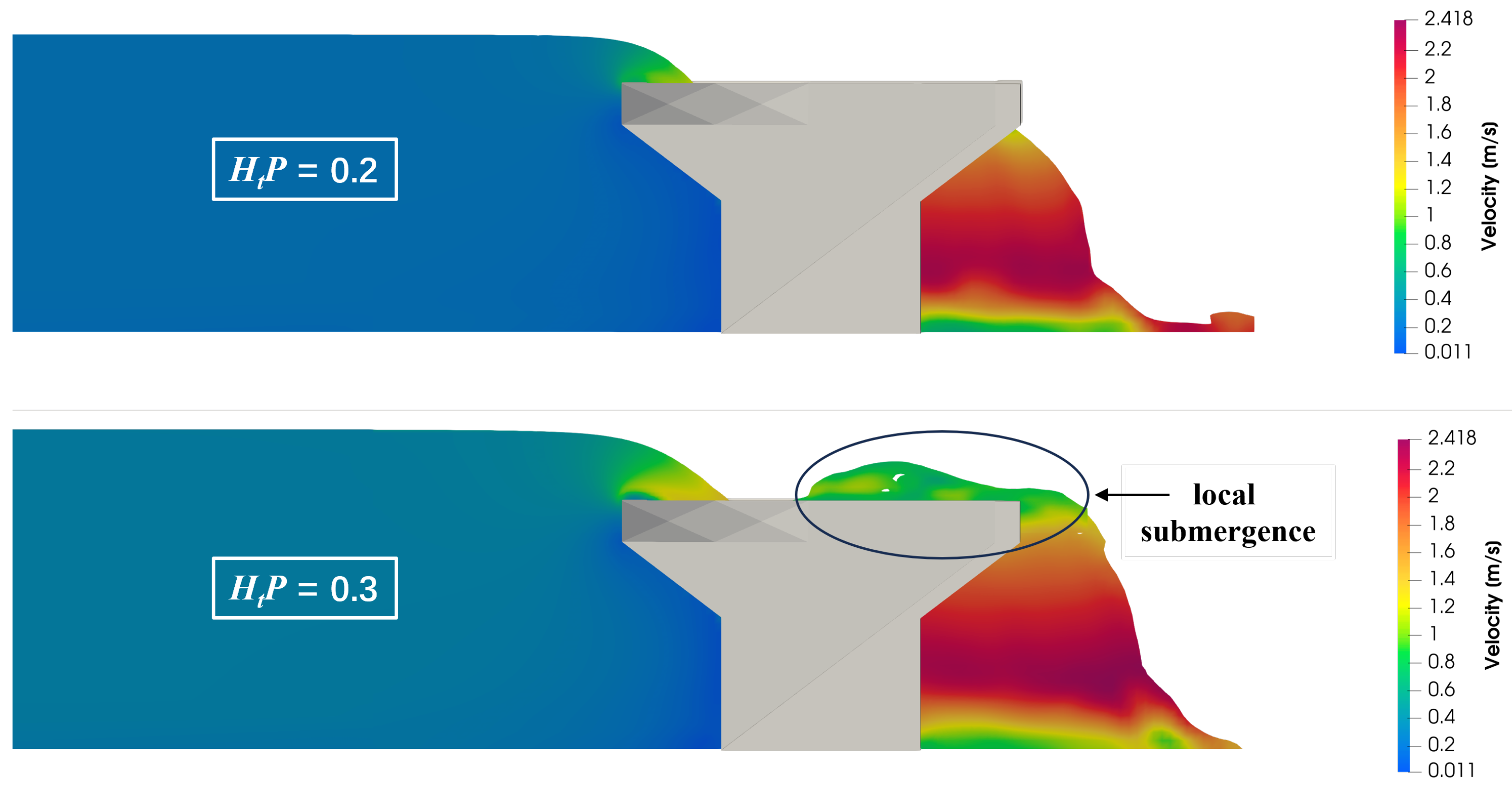
  • The intergration of the rectangular shape on the upstream side optimizes the outlet cross-section, offering more space for the flow evacuation and enhancing the mitigation of the nappe interference effect.
Figure 5 presents an exemplary comparative analysis of the simulated submergence region length between the reference model TPKW 1.00 and CPKW 0.71 , which was derived from TPKW 1.00 by incorporating a rectangular layout. It is evident that at H t P 1 = 0.2 , the composite design significantly reduced the nappe interference region length, thereby facilitating more sufficient outflow over the upstream apex and side walls.
This phenomenon also explains why CPKWs are able to delay the onset of significant efficiency reduction until the upstream relative head exceeds 0.2. In contrast, extensive previous studies have confirmed that for traditional trapezoidal and rectangular PKWs, the overall efficiency begins to decrease markedly at relative upstream heads below or near 0.1 [29,30,31].

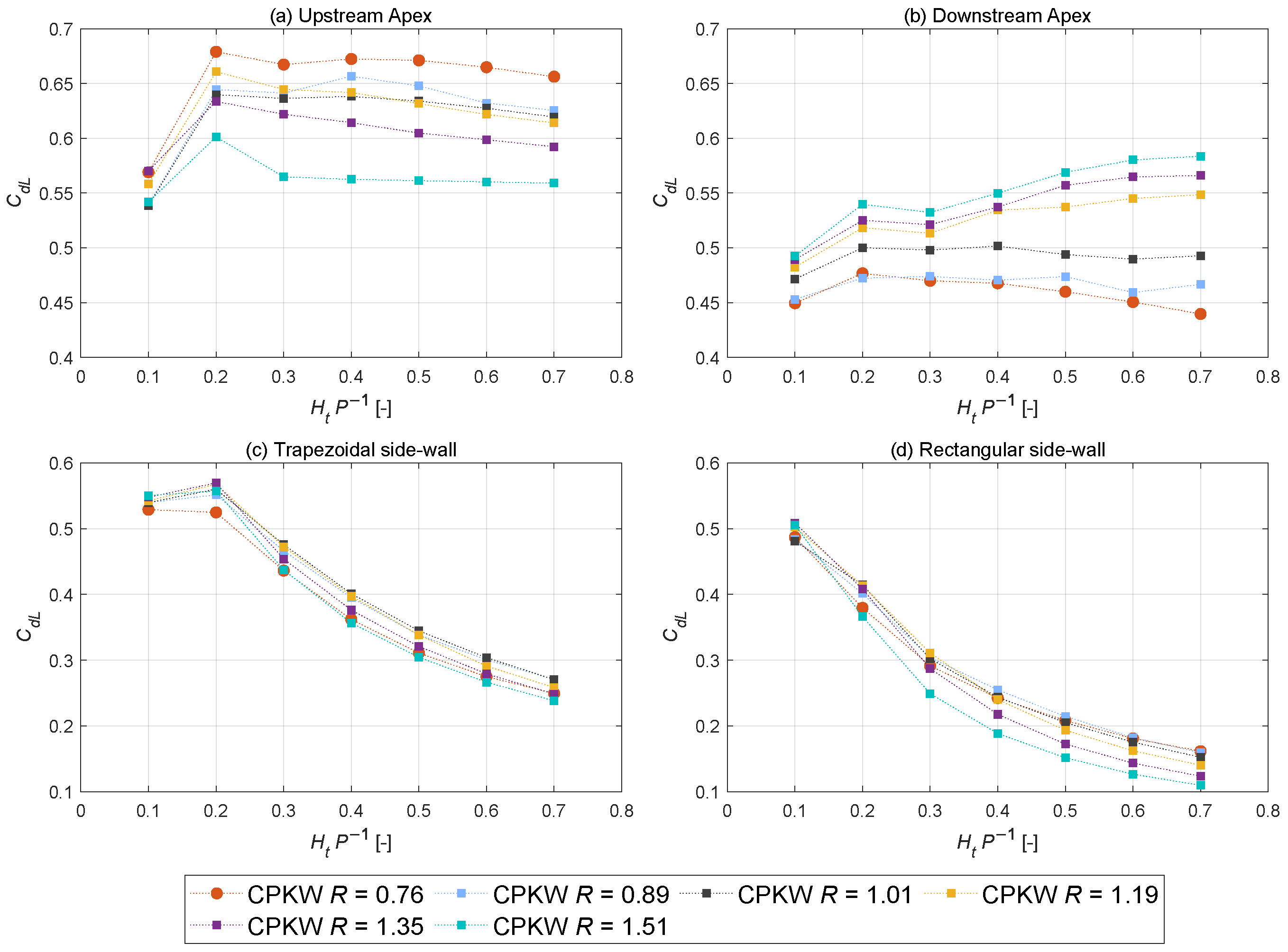
3.2. Influence of Key Width Ratio

Similarly to regular PKWs, Figure 4 indicates that the discharge capacity of the composite configurations could be further improved by optimizing the key width ratio. Nonetheless, in order to maintain a constant total weir width, any increase in the inlet key width must be accompanied by a corresponding reduction in the outlet section. Consequently, excessive enlargement of the key width ratio will result in a significant narrowing of the outlet cross-section, thereby exacerbating local submergence effects and reducing the overall discharge performance of the weir.
In general, the total discharge over a half-unit composite PKW can be devided into four crest segments (see Figure 6):
  • The upstream apex;
  • The downstream apex;
  • The rectangular section of the side wall;
  • The trapezoidal section of the side wall.
Figure 7 presents the evolution of the discharge efficiency under increasing relative upstream heads ( H t P 1 ) for each crest segment. As expected, due to the intensifying interference between the outflow from the adjacent side walls and the upstream apex induced by the reduction in the outlet key width, the discharge efficiency of upstream apex decreased with increasing key width ratio. For the same reason, the hindered outflow over the upstream apex then led to an increase in the flow depth within the inlet, raising the hydraulic gradient. As a result, the downstream apex exhibited the opposite behavior compared to the upstream apex, with its discharge efficiency increasing as the key width ratio grew. Additionally, as illustrated in Figure 7b, it can be observed that for H t P 1 > 0.3 , while the downstream apex discharge efficiency of the models with a key width ratio R > 1.01 clearly exhibited an increasing trend, models featuring R 1.01 tended to decrease as the upstream head grew. The most likely reason for this behavior is that, at high upstream heads with H t P 1 > 0.3 , the intense adjacent side nappe interaction not only impedes the outflow from the upstream apex but also hinders the side wall discharge. This issue is exacerbated in models with larger key width ratios, which forces a larger portion of the flow to be discharged through the downstream apex. It should be noted that the modest relative decline in efficiency of the downstream apex between H t P 1 = 0.2 and H t P 1 = 0.3 is primarily attributable to the numerical model’s slight overprediction of the overall discharge efficiency at H t P 1 = 0.2 (as can be seen in Figure 3). This systematic overestimation at the lower head amplifies the perceived relative reduction at H t P 1 = 0.3 , despite minimal absolute changes in hydraulic performance.
Furthermore, Figure 7b,c show that the trapezoidal section of side wall was generally more efficient than the rectangular part. This is primarily attributed to the following reasons: (1) the trapezoidal side-wall section is positioned downstream and is therefore less susceptible to the outflow from the upstream apex; and (2) the trapezoidal design facilitates a diffusion-like outlet cross-section, which mitigates the interference between lateral overflows. In addition, the trapezoidal part of side wall reached its maximum efficiency at H t P 1 = 0.2 , after which the efficiency began to decrease. In addition, Figure 8 provides an exemplary comparison of the nappe behavior in the CPKW 0.76 configuration at H t P 1 = 0.2 and at H t P 1 = 0.3 . The visual evidence demonstrates that significant local submergence developed within this upstream head range, predominantly near the downstream region of the outlet section. Coupled with the quantitative analysis, these observations collectively confirm that the critical upstream relative head, beyond which the local nappe interference starts to affect the downstream part of side wall, lies within the range of 0.2 to 0.3. Moreover, summarizing all data presented in Figure 7, it can also be concluded that optimizing the key width ratio had a greater impact on the efficiency of the up- and downstream apexes than on the side walls, particularly under high heads.

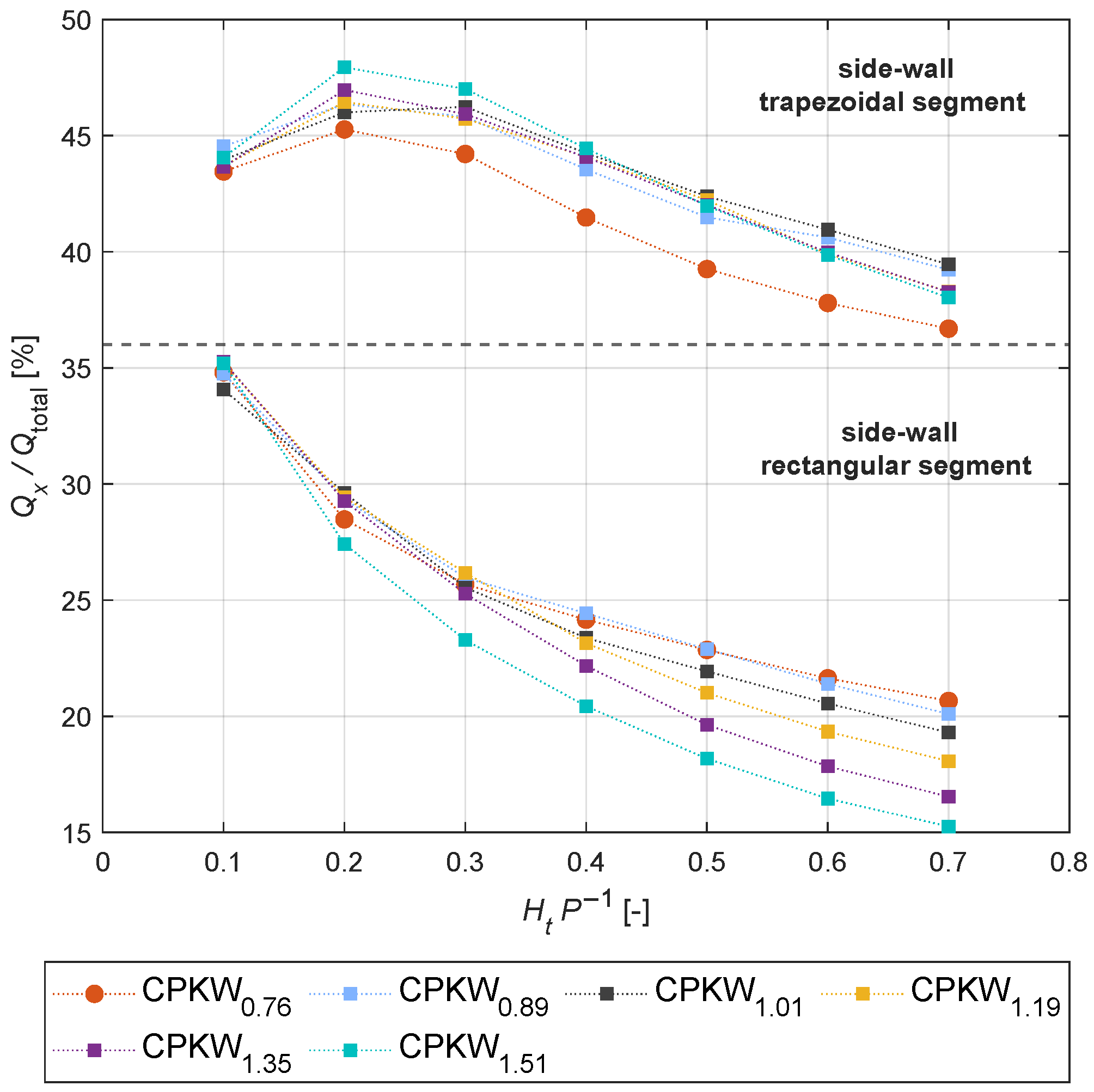
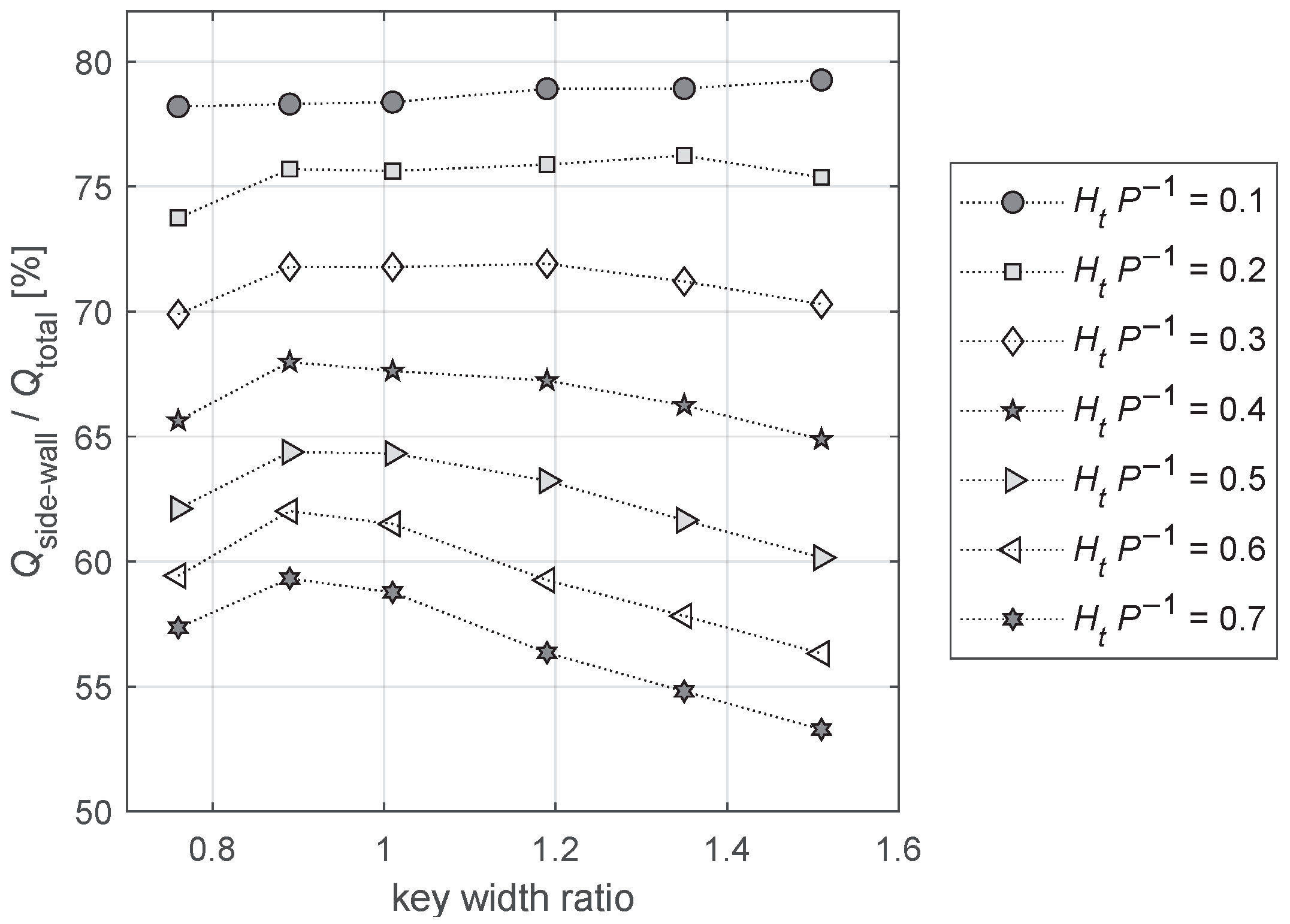
3.3. Discharge Distribution of CPKWs

Since the length of the side walls constitutes a significant proportion (78.6%) of the total crest length, the discharge efficiency of the side walls plays a decisive role in the overall performance of a PKW. Therefore, the proportion of side-wall discharge relative to the overall discharge could be used as an indicator of the discharge efficiency. A higher proportion suggests that the side wall is contributing effectively to the overall performance, typically resulting in better discharge efficiency. Conversely, a lower proportion indicates that the sidewall’s performance is restricted, which generally leads to a reduction in the overall discharge efficiency.
For models with varying key width ratios and different upstream heads, Figure 9 presents the proportion of discharge from the rectangular and trapezoidal side-wall segments ( Q x ) relative to the total discharge of the entire structure (Qtotal). For the rectangular section, differences between models with varying key width ratios became noticeable only when the relative upstream head exceeded 0.3 with the exception of TPKW 1.51 , which featured the largest key width ratio considered within this study. This behavior further supports the inference that for models with R 1.35 , H t P 1 = 0.2–0.3 is the critical threshold beyond which the nappe interference becomes significant and affects the lateral outflow. Relative to the rectangular segment of side wall, the trapezoidal part contributed a notably higher portion to the overall discharge across the entire tested range. As shown in the upper part of Figure 9, the trapezoidal side-wall segment should maintain a key width ratio greater than 0.89 to avoid a significant reduction in discharge contribution.
Moreover, Figure 10 illustrates the percentage contribution of the entire side wall to the overall discharge. For low heads with H t P 1 0.2 , the side walls contributed an equivalent portion of the discharge relative to their length ratio (78% of the total crest length), indicating a uniform flow distribution. As the local submergence region extended with growing upstream head, the proportion of discharge contributed by the side walls generally decreased. It can be seen that under large heads, the percentage discharge contribution of side wall for models with large key width ratios dropped to under 60%, meaning that almost half of the total discharge was evacuated over up- and downstream apexes, which was only 21.4% of the total crest length. For H t P 1 0.2 , the results demonstrate that increasing the key width ratio slightly enhanced the contribution of the side wall to the total discharge. In contrast, for upstream relative heads greater than 0.3, key width ratios exceeding 1.01 had a negative impact on the side-wall efficiency, resulting in a descending trend as R further increased. Based on these findings, the optimum range of key width ratio for the specific composite configuration can be identified to be between 0.89 and 1.01.

4. Conclusions

The present study introduces an innovative composite piano key weir (PKW) configuration that integrates conventional rectangular and trapezoidal PKW structures in both the vertical direction and horizontal planes. Using a flat-crested trapezoidal PKW with a key width ratio R = 1 as reference, this study investigated the discharge efficiency of the composite configuration through numerical simulations. Additionally, to optimize its geometric design, configurations with six different key width ratios were evaluated. Based on the numerical results, the following conclusions can be drawn:
  • Enhanced Discharge Performance: Compared to conventional trapezoidal piano key weirs (TPKWs), the proposed innovative composite configuration enlarges the total crest length while effectively mitigating local nappe interference, resulting in improved overall discharge efficiency.
  • Optimal Key Width Ratio: The discharge performance of CPKW can be further enhanced by optimizing the key width ratio. Results show that the key width ratio has a greater impact on the efficiency of up- and downstream apexes than on the side wall. For the specific composite configurations investigated in this study, the optimal key width ratio, which achieves the best balance between maximizing inlet efficiency and mitigating the adverse effects of local submergence, is identified to be within the range of R = 0.89–1.01.
  • Discharge Distribution: For low heads ( H t P 1 < 0.2 ), a uniform discharge distribution was observed, where the side walls contributed an equivalent portion of discharge relative to their length. Beyond H t P 1 = 0.3 , the proportion of discharge contributed by the side walls generally decreased, indicating the critical threshold at which the local submergence became significant and started to affects the lateral outflow. Moreover, the trapezoidal section of the side wall was observed to be more efficient and contributed a higher portion of discharge than the rectangular part, since it was less affected by the lateral and longitudinal nappe interference.
In summary, the innovative composite PKW design offers an alternative for enhancing the discharge capacity of existing dam infrastructures. However, its implementation may pose challenges, such as increased construction complexity due to the integration of trapezoidal and rectangular geometries, which requires precise geometric control compared to traditional PKWs. Furthermore, long-term structural stability and maintenance implications should be evaluated to ensure dam safety. In addition, it should also be noted that although the numerical approach employed in this study is able to calculate the resulting c d values with satisfactory accuracy, deviations may still exist in resolving highly localized flow features such as detailed nappe trajectories and interference effects. These phenomena are inherently sensitive to turbulence modeling assumptions, air entrainment dynamics, and interfacial curvature factors. Therefore, experimental studies are required in future research, and exploration of other geometric parameters may further enhance the performance of such composite configurations.

Author Contributions

Conceptualization, X.S.; methodology, X.S. and S.J.; software, S.J., X.S. and M.O.; validation, S.J. and X.S.; formal analysis, S.J. and X.S.; investigation, S.J.; resources, X.S. and M.O.; data curation, S.J.; writing—original draft preparation, S.J. and X.S.; writing—review and editing, X.S. and M.O.; visualization, S.J. and X.S.; supervision, X.S.; funding acquisition, X.S. All authors have read and agreed to the published version of the manuscript.

Funding

This research was funded by the Scientific Research Project of the Zhejiang Provincial Department of Education (grant number: Y202351799 and Y202454989) and the research start-up fund of Zhejiang University of Science and Technology (grant number: F015117P03).

Data Availability Statement

The raw data supporting the conclusions of this article will be made available by the authors upon request.

Conflicts of Interest

The authors declare no conflicts of interest.

Notations

The following notations are used in this manuscript:
Bweir length (m)
B b weir base length (m)
B i inlet key overhang length (m)
B o outlet key overhang length (m)
C d L discharge coefficient related to total crest center-line length
C d W discharge coefficient related to total weir width
erelative error
ggravity acceleration ( ms 2 )
F s grid refinement factor
h p parapet wall height (m)
h t sum of the piezometric head above the weir crest (m)
H t total upstream head relative to weir crest (m)
Ltotal crest center-line length of tested weirs (m)
Pweir height (m)
Qdischarge ( ls 1 )
Rratio of inlet key width upstream to outlet key width downstream
S W i trapezoidal side-wall length (m)
S W o rectangular side-wall length (m)
vflow rate ( ms 1 )
Wtotal weir width (m)
W i , d inlet key width downstream (m)
W i , u inlet key width upstream (m)
W o , d outlet key width downstream (m)
W o , u outlet key width upstream (m)
α side-wall angle (degree)

Abbreviations

The following abbreviations are used in this manuscript:
CFDscomputational fluid dynamics
CPKWcomposite piano key weir with rectangular and trapeyoidal planforms
expexperimental
FAVORfractional area/volume obstacle representation
GCIgrid convergence index
numnumerical model
PKWpiano key weir
RNGre-normalization group
TPKWpiano key weir with trapezoidal planform
VOFvolume of fluid

References

  1. Seneviratne, S.I.; Zhang, X.; Adnan, M.; Badi, W.; Dereczynski, C.; Di Luca, A.; Ghosh, S.; Iskandar, I.; Kossin, J.; Lewis, S.; et al. Weather and Climate Extreme Events in a Changing Climate. In Climate Change 2021: The Physical Science Basis. Contribution of Working Group I to the Sixth Assessment Report of the Intergovernmental Panel on Climate Change; Masson-Delmotte, V., Zhai, P., Pirani, A., Connors, S.L., Péan, C., Berger, S., Caud, N., Chen, Y., Goldfarb, L., Gomis, M.I., et al., Eds.; Cambridge University Press: Cambridge, UK, 2021; pp. 2771–3142. [Google Scholar]
  2. Milly, P.C.D.; Betancourt, J.; Falkenmark, M.; Hirsch, R.M.; Kundzewicz, Z.W.; Lettenmaier, D.P.; Stouffer, R.J. Stationarity is dead: Whither water management? Science 2008, 319, 573–574. [Google Scholar] [PubMed]
  3. Hirabayashi, Y.; Mahendran, R.; Koirala, S.; Konoshima, L.; Yamazaki, D.; Watanabe, S.; Kim, H.; Kanae, S. Global flood risk under climate change. Nat. Clim. Change 2013, 3, 816–821. [Google Scholar]
  4. Arnell, N.W.; Gosling, S.N. The impacts of climate change on river flood risk at the global scale. Clim. Change 2016, 134, 387–401. [Google Scholar]
  5. Kundzewicz, Z.W.; Kanae, S.; Seneviratne, S.I.; Handmer, J.; Nicholls, N.; Peduzzi, P.; Mechler, R.; Bouwer, L.M.; Arnell, N.; Mach, K.; et al. Flood risk and climate change: Global and regional perspectives. Hydrol. Sci. J. 2014, 59, 1–28. [Google Scholar] [CrossRef]
  6. Rosenberger, L.; Leandro, J.; Pauleit, S.; Erlwein, S. Sustainable stormwater management under the impact of climate change and urban densification. J. Hydrol. 2021, 596, 126137. [Google Scholar]
  7. Machiels, O.; Erpicum, S.; Dewals, B.J.; Archambeau, P.; Pirotton, M. Experimental Observation of Flow Characteristics over A Piano Key Weir. J. Hydraul. Res. 2011, 49, 359–366. [Google Scholar]
  8. Leite Ribeiro, M.; Bieri, M.; Boillat, J.-L.; Schleiss, A.J.; Singhal, G.; Sharma, N. Discharge Capacity of Piano Key Weirs. J. Hydraul. Eng. 2012, 138, 199–203. [Google Scholar]
  9. Lempérière, F.; Ouamane, A. The piano keys weir: A new cost-effective solution for spillways. Int. J. Hydropower Dams 2003, 10, 144–149. [Google Scholar]
  10. Crookston, B.M.; Erpicum, S.; Tullis, B.P.; Laugier, F. Hydraulics of Labyrinth and Piano Key Weirs: 100 Years of Prototype Structures, Advancements, and Future Research Needs. J. Hydraul. Eng. 2019, 145, 02519004. [Google Scholar]
  11. Singh, D.; Kumar, M. Hydraulic Design and Analysis of Piano Key Weirs: A Review. Arab. J. Sci. Eng. 2022, 47, 5093–5107. [Google Scholar]
  12. Eslinger, K.R.; Crookston, B.M. Energy Dissipation of Type a Piano Key Weirs. Water 2020, 12, 1253. [Google Scholar] [CrossRef]
  13. Bekheet, A.A.; AboulAtta, N.M.; Saad, N.Y.; El-Molla, D.A. Effect of the shape and type of piano key Weirs on the flow efficiency. Ain Shams Eng. J. 2022, 13, 101620. [Google Scholar]
  14. Leite Ribeiro, M.; Pfister, M.; Schleiss, A.J.; Boillat, J.L. Hydraulic design of A-type Piano Key Weirs. J. Hydraul. Res. 2012, 50, 400–408. [Google Scholar]
  15. Leite Ribeiro, M.; Boillat, J.L.; Schleiss, A.J. Experimental parametric study for hydraulic design of PKWs. In Proceedings of the International Conference on Labyrinth and Piano Key Weirs-PKW 2011, Liège, Belgium, 9–11 February 2011; pp. 183–190. [Google Scholar]
  16. Machiels, O.; Pirotton, M.; Pierre, A.; Dewals, B.; Erpicum, S. Experimental parametric study and design of Piano Key Weirs. J. Hydraul. Res. 2014, 52, 326–335. [Google Scholar] [CrossRef]
  17. Li, G.; Li, S.; Hu, Y. The effect of the inlet/outlet width ratio on the discharge of piano key weirs. J. Hydraul. Res. 2019, 58, 594–604. [Google Scholar] [CrossRef]
  18. Li, S.; Li, G.; Jiang, D.; Ning, J. Influence of auxiliary geometric parameters on discharge capacity of piano key weirs. Flow Meas. Instrum. 2020, 72, 101719. [Google Scholar]
  19. Shen, X.; Oertel, M. Influence of Piano Key Weir Crest Shapes on Flow Characteristics, Scale Effects, and Energy Dissipation for In-Channel Application. J. Hydraul. Eng. 2023, 149, 04023010. [Google Scholar]
  20. Cicero, G.M.; Delisle, J.R.; Lefebvre, V.; Vermeulen, J. Experimental and numerical study of the hydraulic performance of a trapezoidal Piano Key weir. In Proceedings of the Second International Workshop on Labyrinth and Piano Key Weirs 2013, Paris, France, 20–22 November 2013; pp. 265–272. [Google Scholar]
  21. Kumar, M.; Sihag, P.; Tiwari, N.K.; Ranjan, S. Experimental study and modelling discharge coefficient of trapezoidal and rectangular piano key weirs. Appl. Water Sci. 2020, 10, 43. [Google Scholar]
  22. Yang, J.; Li, S.; Helgesson, A.; Skepparkrans, E.; Ansell, A. Geometric Modification of Piano Key Weirs to Enhance Hydraulic Performance and Discharge Capacity. Water 2021, 15, 4148. [Google Scholar] [CrossRef]
  23. Shen, X.; Oertel, M. Comparative Study of Nonsymmetrical Trapezoidal and Rectangular Piano Key Weirs with Varying Key Width Ratios. J. Hydraul. Eng. 2021, 147, 0421045. [Google Scholar]
  24. Pralong, J.; Montarros, F.; Blancher, B.; Laugier, F. A sensitivity analysis of Piano Key Weirs geometrical parameters based on 3D numerical modeling. In Proceedings of the International Conference on Labyrinth and Piano Key Weirs-PKW 2011, Liège, Belgium, 9–11 February 2011; pp. 133–139. [Google Scholar]
  25. Pfister, M.; Boillat, J.L.; Schleiss, A.J.; Laugier, F.; Leite Ribeiro, M. Piano key weirs as efficient spillway structure. In Proceedings of the 24th Congress of CIGB-ICOLD, Kyoto, Japan, 6–8 June 2012; pp. 176–186. [Google Scholar]
  26. Safarzadeh, A.; Noroozi, B. 3D Hydrodynamics of Trapezoidal Piano Key Spillways. Int. J. Civ. Eng. 2017, 15, 89–101. [Google Scholar] [CrossRef]
  27. Celik, I.B.; Ghia, U.; Roache, P.J.; Freitas, C.J.; Coleman, H.; Raad, P.E. Procedure for Estimation and Reporting of Uncertainty Due to Discretization in CFD Applications. J. Fluids Eng. 2008, 130, 078001. [Google Scholar]
  28. Savage, B.M.; Crookston, B.M.; Paxson, G.S. Physical and Numerical Modeling of Large Headwater Ratios for a 15° Labyrinth Spillway. J. Hydraul. Eng. 2016, 138, 04016046. [Google Scholar]
  29. Hu, H.; Qian, Z.; Yang, W.; Hou, D.; Du, L. Numerical study of characteristics and discharge capacity of piano key weirs. Flow Meas. Instrum. 2018, 62, 27–32. [Google Scholar]
  30. Crookston, B.M.; Anderson, R.M.; Tullis, B.P. Free-flow discharge estimation method for Piano Key weir geometries. J. Hydro-Environ. Res. 2018, 19, 160–167. [Google Scholar]
  31. Anderson, R.M.; Tullis, B.P. Piano Key Weir: Reservoir versus Channel Application. J. Irrig. Drain. Eng. 2012, 138, 773–776. [Google Scholar] [CrossRef]
Figure 1. Exemplary schematic explanation of a Composite Piano-Key-Weir configuration.
Water 17 00921 g001
Figure 2. Investigated piano key weir plan form geometry.
Water 17 00921 g002
Figure 3. Comparison of experimented and simulated discharge coefficients of the trapezoidal reference model.
Water 17 00921 g003
Figure 4. Comparison of total discharge efficiency of CPKWs with varied key width ratios: (a) comparison of resulting C d W -values; (b) relative percentage deviation.
Water 17 00921 g004
Figure 5. Comparison of nappe interference region between TPKW 1.00 and CPKW 0.76 at H t P 1 = 0.2 .
Water 17 00921 g005
Figure 6. Illustration for crest segments of the composite configuration.
Water 17 00921 g006
Figure 7. Discharge efficiency of each crest segment for CPKWs with varied key width ratios.
Water 17 00921 g007
Figure 8. Exemplary comparison of nappe behavior in the CPKW 0.76 configuration at H t P 1 = 0.2 and H t P 1 = 0.3 .
Water 17 00921 g008
Figure 9. Evolution of percentage discharge proportion for each side-wall segment.
Water 17 00921 g009
Figure 10. Percentage proportion of side-wall discharge relative to total discharge.
Water 17 00921 g010
Table 1. Summary of geometrical parameters of reference model and tested numerical models.
ModelTypeR [1]PBLW W i , u W i , d W o , u W o , d h p  [2] α
Trapezoidal Piano Key Weir
TPKW 1.00 exp [3]1.003004801103300201.498.698.6201.4156.5
Composite Piano Key Weirs
CPKW 0.76 num [4]0.763004801148300153.498.6146.6201.4506.5
CPKW 0.89 num0.89167.0112.2133.0187.8
CPKW 1.01 num1.01179.1124.3120.9175.7
CPKW 1.19 num1.19192.6137.8107.4162.2
CPKW 1.35 num1.35204.0149.296.0150.8
CPKW 1.51 num1.51213.5158.786.5141.3
Notes: [1] R = key width ratio ( W i , u W o , d 1 ); [2]  h p = parapet wall height; [3] exp = experimental model; [4] num = numerical model. Bold numbers indicate parameters that are kept constant.
Table 2. Exemplary GCI calculation for CPKW 0.71 at H t P 1 = 0.4 based on resulting discharge.
Initial GridRepresentativeTotal GridRefinementQRelativeGCIComputation
Size [mm]Grid Size [mm]NumberFactor  F s [ ls 1 ]Error ( e )[%]Time [h]
129.5118,944-26.02--4
107.6218,2201.24525.900.00461.507
86.0422,0001.25725.810.00351.0714
Disclaimer/Publisher’s Note: The statements, opinions and data contained in all publications are solely those of the individual author(s) and contributor(s) and not of MDPI and/or the editor(s). MDPI and/or the editor(s) disclaim responsibility for any injury to people or property resulting from any ideas, methods, instructions or products referred to in the content.

