Article

Performance of Emitters in Drip Irrigation Systems Using Computational Fluid Dynamic Analysis †

by
Mauro De Marchis
1,*,‡,
Federica Bruno
2,‡,
Domenico Saccone
2,‡ and
Enrico Napoli
1,‡
1
Department of Engineering, Università degli Studi Palermo, 90128 Palermo, Italy
2
Department of Engineering and Architecture, Università di Enna Kore, 94100 Enna, Italy
*
Author to whom correspondence should be addressed.
This paper is an extended version of our paper published in Saccone, D.; De Marchis, M. Optmization of the design of labyinth emitter for agriculture irrigation using computational fluid dynamic analysis. In Proceedings of the AlP Conference Proceedings, Thessaloniki, Greece, 14–18 March 2018; AlP Publishing LLC: Atlanta, GA, USA, 2018; Volume 2040, No. 1., p. 140013.
These authors contributed equally to this work.
Water 2025, 17(5), 689; https://doi.org/10.3390/w17050689
Submission received: 31 December 2024 / Revised: 4 February 2025 / Accepted: 25 February 2025 / Published: 27 February 2025
(This article belongs to the Special Issue Advances in Agricultural Irrigation Management and Technology)

Abstract

:
Flat drippers are widely used in agricultural irrigation systems to ensure precise water distribution. This study investigates the optimization of flat drippers through Computational Fluid Dynamics (CFDs) simulations, focusing on the channel geometry. These emitters have a particular configuration of the labyrinth channel appropriately shaped to ensure high turbulence and dissipation of the hydraulic load. CFDs techniques are particularly suitable to investigate the labyrinth design and optimization. Here, by analyzing seven different dripper models with varying dissipation channel sizes, the relationship between flow rate (liters per hour) and pipe pressure (kPa) was studied. Simulations were performed for six inlet pressures in the range between 50 and 175 kPa, with steps of 25 kPa, allowing for the derivation of the pressure–flow curve and the optimization of the emitter exponent. The value of the exponent is closely linked to the conformation of the channel and is standardized by the International Organization for Standardization (ISO) 9261:2004. Additionally, the influence of the labyrinth channel’s cross-sectional area on flow rate was examined, providing insights into design improvements for enhanced hydraulic performance. The proposed optimization could lead to significant water savings and enhanced agricultural productivity by improving the efficiency of irrigation systems.

1. Introduction

In water scarcity conditions, it is fundamental to achieve an optimal management of hydraulic infrastructures [1,2,3,4] to use the resource during dry periods. Agricultural procedures are particularly affected by drought periods, considering that water for irrigation accounts for nearly 70% of the total water consumption worldwide. To reduce this amount of consumption, the scientific community has focused on innovative irrigation technologies and reducing water use while increasing irrigation performance. In this regard, the drip irrigation system has found particular interest, as it fully reflects the characteristics previously mentioned. Essentially, drip elements are interposed at regular intervals inside polyethylene pipes. The design of the drippers is fundamental to rule the flow rate of the emitter. Specifically, it was demonstrated that different labyrinth channels give different discharges. By now, projecting a drip is customary using Computational Fluid Dynamics (CFDs), and few studies have been performed through experiments (see among others the study of [5] and the literature cited therein). More recently, a coupled approach was used, validating the CFD results through an experimental campaign. The role of CFDs in emitter design has been pivotal, enabling the simulation of internal flow dynamics and the evaluation of complex structural interactions. Some research projects have been carried out to investigate the labyrinth shape. Among these studies, ref. [6] performed CFDs analysis to calculate the flow rate–pressure relationship. The authors analyzed the velocity of the fluid inside the channel and found that the maximum values were obtained near the tooth with values of 1.6–2.8 m/s. Ref. [7] studied a 3D model of a dripper using the CFDs method. They obtained the distribution of velocity and pressure in the computational domain and compared the results with the literature data. Ref. [8] conducted numerical simulations on emitters with arc-type labyrinth channels; subsequently, to verify the results, they performed experiments on real models, focusing on the relationship between flow rate and pressure. The authors noticed how fluid dynamics simulations tended to overestimate the flow by about 10%. Ref. [9] analyzed, through numerical simulations and experiments, the flow characteristics in a labyrinth channel emitter. The results showed that the flow inside the channel was turbulent even at low Reynolds numbers. More recently, ref. [10] conducted numerical simulations on emitters with rectangular and zigzag labyrinth channels. The flow rate was calculated for the various models and compared with the measurement of experimental results obtained from the prototype. They found a gap of 9% between the experimental results and turbulence flow model. Furthermore, ref. [11] studied a pressure-compensating emitter through a step-by-step computational fluid dynamics method; the comparison between the data obtained experimentally and those simulated with Fluent highlighted a gap of 5%. Ref. [12] carried out a study aimed at detecting the loss of load in pipes containing cylindrical emitters. The domain consisted of five in-line cylindrical emitters with a capacity of 4 L/h positioned at a distance of 250 mm. Analyzing the results, they obtained that the maximum simulation error was equal to 8.82%. Prototype development and hydraulic evaluation have provided essential insights into emitter performance. Ref. [13] designed a subsurface drip irrigation emitter and demonstrated its ability to minimize root intrusion and clogging, underscoring the importance of structural design in improving durability and uniformity. Building on these foundations, ref. [14] proposed a simplified method to estimate the discharge of microporous ceramic emitters, emphasizing the role of material properties and structural parameters in maintaining consistent discharge rates. Drip irrigation systems have revolutionized water management in agriculture, offering significant improvements in water use efficiency and crop yield. Emitters, as the core components of these systems, regulate water flow and ensure uniform distribution to the root zones of plants. However, challenges such as hydraulic inefficiencies, emitter clogging, and suboptimal performance in varying operational conditions persist, necessitating ongoing research and innovation. Recent studies have advanced our understanding of emitter design and performance optimization. For instance, ref. [15] proposed a novel variable discharge emitter (VDE) capable of dual functionality for irrigation and salt leaching under different working pressures. Similarly, ref. [16] examined the effects of compensation chamber structures on the hydraulic performance of pressure-compensating emitters, providing insights into optimizing flow uniformity under varying pressures. Emitter clogging remains a persistent issue, particularly in systems exposed to poor water quality. Ref. [17] demonstrated that micro/nano aeration could significantly reduce clogging by controlling microbial activity and biofilm formation within the emitter. Additionally, ref. [18] employed CFDs to optimize emitter inlet structures, enhancing their anti-clogging performance and operational stability. Ref. [19] simulated flow characteristics within labyrinth milli-channels, revealing mechanisms for improving emitter efficiency.
The literature cited above highlights the various factors influencing emitter performance, with specific focus on pressure–discharge relationships or anti-clogging mechanisms induced by poor water quality. Less studied is the relationship between flow rate and water temperature, which directly affects water viscosity. Among others, ref. [20] conducted an experimental campaign to analyze the effects of different water temperatures and pressures on the discharge of the emitter. Their findings indicate that, in general, emitter discharge increases with rising temperature. However, under typical operating pressures of 90–120 kPa, the differences in emitter discharge across varying water temperatures remained relatively small (approximately 1%). Later, ref. [21] expanded on this research through laboratory experiments, observing that the average emitter discharge significantly increased with rising water temperature in non-pressure-compensating emitters, while the increase was more moderate in pressure-compensating emitters. Specifically, an increase in water temperature from 20 °C to 50 °C resulted in discharge increases of approximately 5% for non-pressure-compensating emitters and 3% for pressure-compensating emitters. In addition, a linear relationship was observed between discharge and water temperature.
The influence of water quality on emitter performance has also been extensively studied, primarily through laboratory experiments. Recently, ref. [22] and other researchers have investigated the impact of water quality in drip irrigation systems, focusing on flow path structure and operating conditions in relation to clogging characteristics. However, no clear consensus has been reached, as discrepancies persist regarding the effects of sediment concentration, particle size, flow path dimensions, and rated flow rates. For example, some studies suggest that emitter clogging initially decreases and then increases with rising sediment concentration, while others report a direct increase in clogging as sediment concentration rises.
Despite its significance, the effect of water quality on emitter performance falls outside the scope of this study, which focuses primarily on the influence of geometrical design.
Furthermore, studies on structural parameters, such as those by [23], have elucidated the impact of geometric features on the hydraulic performance of the emitter, leading to novel designs such as the Y-shaped emitter. Machine learning approaches have also been used to predict the performance of the emitter. For example, ref. [24] used machine learning techniques to forecast flow regime indices in stellate labyrinth channel emitters, demonstrating the potential for data-driven optimization. Drip irrigation systems have become indispensable in modern agriculture, providing efficient water use and improving crop yields. Emitters play a critical role in ensuring the uniform distribution of water to the root zone, but their performance is often affected by clogging, hydraulic inefficiencies, and variability in operational conditions. Addressing these challenges requires advancements in emitter design and an in-depth understanding of their hydraulic behavior. Recent research has leveraged CFDs to explore internal flow characteristics and optimize structural parameters. Ref. [25] analyzed the core structural parameters of stellate labyrinth channel emitters, providing critical insights into how vortex formation influences hydraulic performance. Similarly, ref. [26] focused on optimizing the tooth shapes to enhance anti-clogging performance in emitters, demonstrating the potential of CFDs to improve reliability and extend emitter lifespans.
The energy dissipation mechanisms within labyrinth channel emitters have also been explored. Ref. [27] examined how geometric features influence hydraulic efficiency, proposing novel designs to enhance water distribution and reduce energy losses. In addition to hydraulic performance, the interaction between fluid dynamics and emitter structure has gained attention. Ref. [28] utilized two-way fluid–structure interaction simulations to predict the performance of pressure-compensating emitters, highlighting the importance of multiphysics approaches in emitter design.
From a manufacturing perspective, toothed-labyrinth channels are among the most commonly used designs for emitters due to their short flow paths, compact structure, and low production costs [16,18]. These characteristics make them particularly suitable for large-scale production using cost-effective materials such as polyethylene (PE) or polyvinyl chloride (PVC), which offer durability and resistance to clogging. The combination of optimized hydraulic performance and reduced material usage makes toothed-labyrinth channels an attractive choice for cost-effective emitter design. As highlighted in [29], conventional drip irrigation has evolved into a knowledge-intensive, technology-driven system, primarily designed for larger land holdings (e.g., >4 ha). The capital investment required for such systems ranges between 1500 and 2500 USD per hectare, making affordability a significant concern for smallholder farmers. The development of low-cost drip irrigation (LCDI) systems, which retain the water-saving benefits of conventional drip systems while being economically viable for smaller fields, offers a promising solution to enhance both economic and food security for small-scale farmers. To address cost challenges, ref. [30] proposed an optimized design approach for drip irrigation systems, where the diameters of laterals and submains are determined by minimizing an objective cost function that accounts for both investment and operating expenses. Such optimization strategies contribute to the overall affordability and efficiency of drip irrigation technology. In the proposed study, relative simple drip emitters have been designed, ensuring a balance between cost, durability, and ease of manufacturing.
The studies cited above builds on advancements in emitter design, using CFDs and other modeling approaches to investigate the performance of drip irrigation systems. By analyzing flow dynamics, energy dissipation, and structural optimization, these research works aim to contribute to the development of more efficient, durable, and clog-resistant emitters. Despite this, further efforts are required, especially in the estimation of the law existing between flow rate q and inlet pressure p. In order to give further insights on this issue, numerical simulations have been performed here to investigate the geometry effect of the labyrinth. Drippers consist of three parts: the inlet section that has cavities designed to channel part of the flow inside the emitter and block the particles of excessive size; the labyrinth channel that dissipates the excess hydraulic load generating vortexes in the fluid; and the outlet section consisting of one or more circular holes from which the water exits at atmospheric pressure. The proposed research focuses on the cross-sectional area of the labyrinth, systematically analyzing the effect on the outlet discharge, modeling seven different geometries, and analyzing six pressure values.

2. Materials and Methods

The design of the dripping elements must be such as to allow compliance with the international standard ISO 9261: “Agricultural Irrigation Equipment—Emitters and Emitting Pipes—Specification and Test Methods” [31]. The international standard models the pressure–discharge relation throughout the classic Torricelli’s law, typical of the leakage dispersione [4], where the relation between the flow rate q, in liters per hour, and the inlet pressure in an emitter p, in kilopascal, is given by
q = k · p x
where k is a constant, and x is the emitting exponent. A good dripper must have a low dependence on pressure fluctuations. This is obtained by determining that the value of x in Equation (1) of the regulation does not exceed the value of 0.5.
The literature cited above clearly demonstrates how the exponent coefficient x is deeply influenced by the shape and geometries of the labyrinth. In Figure 1, a schematic representation of the dripper, analyzed in the present research, is reported. A novel flat drip irrigation emitter was developed in terms of water inlet, outlet, and dissipating flow channel structure. Details on the emitters simulated here are reported in Section 2.2.

2.1. Numerical Method
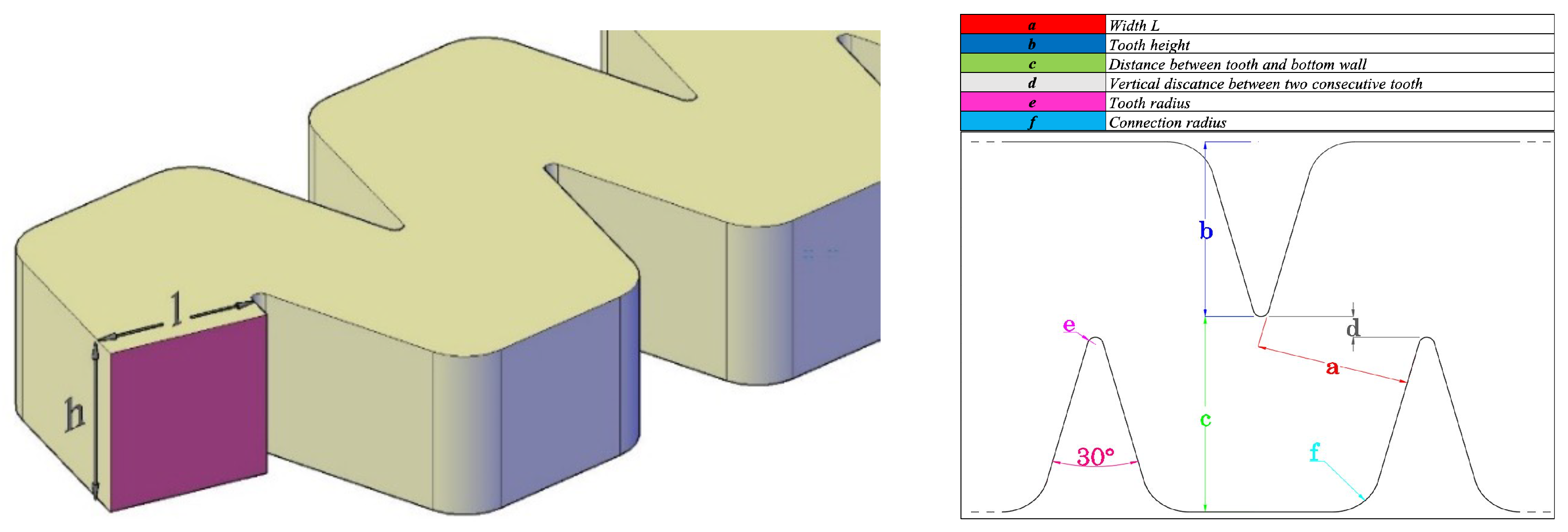
The flow in labyrinth channel emitters is considered to be a viscous incompressible fluid. Two basic governing equations, the continuity equation and the Reynolds-Averaged Navier–Stokes (RANS), were used that, in the summation convention formulation, read as follows:
u i t + u i u j x j ν 2 u i x j x j + 1 ρ p x i + 1 ρ τ i j x j + g z x i = 0 i , j = 1 , , 3
u j x j = 0 j = 1 , , 3
where t is the time, x i the i-th axis, u i is the i-th component of the Reynolds-averaged velocity, ρ is the water density, p is the Reynolds-averaged pressure, g is the gravity acceleration, ν is the kinematic viscosity, and τ i j = ρ u i u j ¯ is the Reynolds stresses, where u i is the fluctuating velocity, and · ¯ indicates Reynolds averaging.
The turbulence closure is achieved by using the k ε turbulence model in the classical formulation based on the Boussinesq assumption on the eddy viscosity ν t :
τ i j = ρ ν t u i x j + u j x i + 2 3 δ i j ρ k
where k is the turbulent kinetic energy (TKE), and δ i j is the Kronecker symbol that has the value 1 if i and j are equal; otherwise it has the value 0.
The eddy viscosity is obtained as
ν t = c μ k 2 ε
where c μ is a closure parameter, and ε is the dissipation rate of the TKE. The time and space distribution of k and ε are obtained through the following:
k t + u i k x j = x j ν t σ k k x j + P ε
ε t + u i ε x j = x j ν t σ ε ε x j + ( c ε 1 P c ε 2 ε ) ε k
where P is the production of the TKE, which is defined as follows:
P = τ i j ρ u i x j + u j x i
The standard values of the model coefficients were used: c μ = 0.09, c ε 1 = 1.44, c ε 2 = 1.92, σ k = 1.0, and σ ε = 1.3.
The numerical scheme used is second-order accurate in both time and space. The algorithm used for the time advancement of the solution is semi-implicit in the vertical direction. Specifically, the vertical diffusive and turbulent terms are discretized using the Crank–Nicolson implicit method, while the Adams–Bashfort explicit scheme is employed for the remaining terms. Implicit discretization was used for the vertical viscous and turbulent terms, since the stability restriction arising from these terms resulted to be much more severe than that related to the horizontal corresponding ones. Details on the numerical model can by found in [32]. The selection of the k ε turbulence model was based on the findings of [19], which provide a comparative analysis of LES and k ε models. In particular, the study examined the Standard k ε model (SKE), the Reynolds Stress Model (RSM), and Large Eddy Simulation (LES). As expected, the results indicate that LES offered the highest accuracy in capturing the hydrodynamic effects on the emitter. However, it required substantial computational resources. Conversely, the SKE model showed good performance in predicting both the main flow and recirculation regions while maintaining a significantly lower computational cost. This trade-off makes SKE the optimal choice in terms of balancing accuracy and computational efficiency, which make it particularly suitable for simulating mean flow characteristics, such as emitter discharge.

2.2. Case Study

The analysis of labyrinth channel design involves numerous parameters, with an almost infinite number of possible geometric variations. For each specific base labyrinth shape, multiple parameters can be explored. Some of these have already been investigated in previous studies cited in the literature. Given the vast range of potential geometries, a systematic approach is required to gain meaningful insights. The most effective method is to keep certain parameters constant while selectively varying others.
In this study, we focused on the effect of the cross-sectional area, a parameter that has been relatively less explored in the literature. Following the methodology of previous studies, we maintained a fixed set of geometric features while systematically varying a single parameter, the cross-sectional area. Future research will extend this investigation to other geometric aspects, such as curvature and tooth shape.
Basically, it was decided to analyze the behavior of different labyrinth geometries keeping the input and output sections constant and changing the width L and the height h of the dissipation channel (see Figure 2). The structure of the single tooth of the channel has the following dimensions: an angle of 30 grades and a radius of connection to the tip of 0.05 mm. Changing the width L and the height h of the channel, seven different configurations were investigated. In Table 1, the geometrical data are reported. For each labyrinth, six different inlet pressures were imposed equal to 50, 75, 100, 125, 150, and 175 kPa. Once the pressure is fixed, it is possible to estimate the exponent x reported in Equation (1).
The physical domain was reproduced into a computational domain through a mesh generated to achieve a balance between computational cost and quality of the results. As usual, the mesh was refined in the regions characterized by the highest velocity gradients. The minimum size and maximum size were set equal to 0.01 mm and 0.1 mm, respectively. The fluid domain calculation grids was about 950,000 tetrahedral cells. The sensitivity analysis confirmed the correctness of the computational grid. In Figure 3 is shown a snapshot of the computational mesh.

3. Results

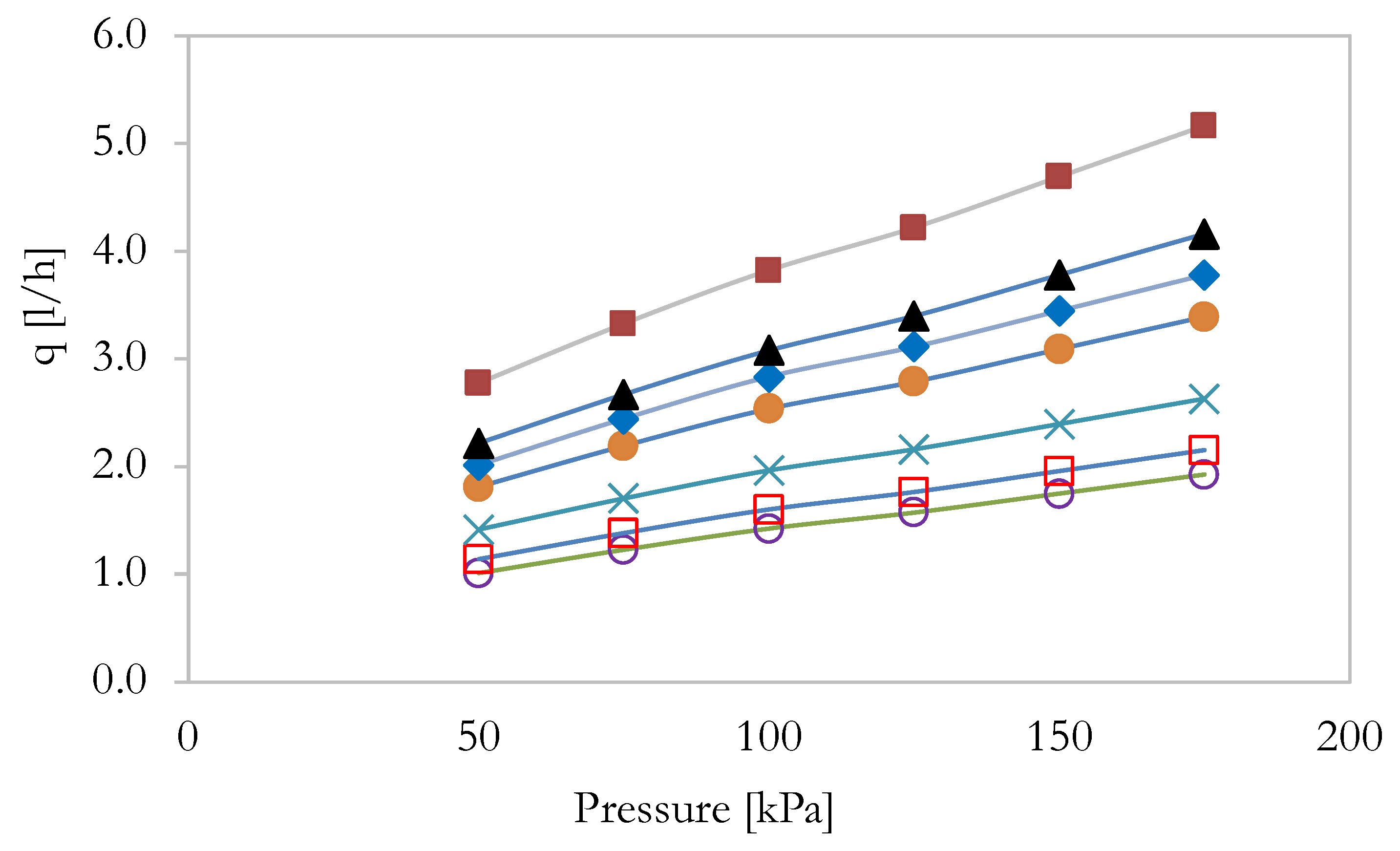
3.1. Discharge Exponent

In order to investigate the discharge exponent x, reported in Equation (1), several numerical simulations were performed. Specifically, for each of the seven geometrical shapes, six different pressure values at the inlet section were imposed. The results are depicted in Figure 4.
Using the numerical simulation results, it was possible to estimate the discharge exponent x and coefficients k (see Equation (1)). Specifically, the coefficients were calculated using the pressure P and the achieved related flow rate q using the following relations:
x = ( l o g P i ) ( l o g q i ¯ 1 n ( ( l o g P i ) ) ) ( l o g q i ¯ ) ( l o g P i ) 2 1 n ( l o g P i ) 2 k = e x p · ( l n q i ¯ n ) x · ( l n P i ) n
where P i is the inlet pressure in kilopascals, n is the number of imposed pressure values, which in this research equaled to seven, and q i ¯ is the mean flow rate in liters per hour. In Table 2, the flow rates obtained for each numerical simulation are reported, whereas in Table 3, the coefficient values x and k are reported. The data show a linear variation of the discharge coefficient k with the cross-sectional area. Looking at the exponent coefficient x, it can be observed how the coefficient was always lower than 0.5 and decreased with the augmentation of the emitter area. The data achieved for Case 3 reveal a slight deviation from the linearity, even though the values were quite close to each others. Overall, the results clearly show a general good performance of the designed labyrinth; the exponent x was, in fact, always within the standard ISO 9261.

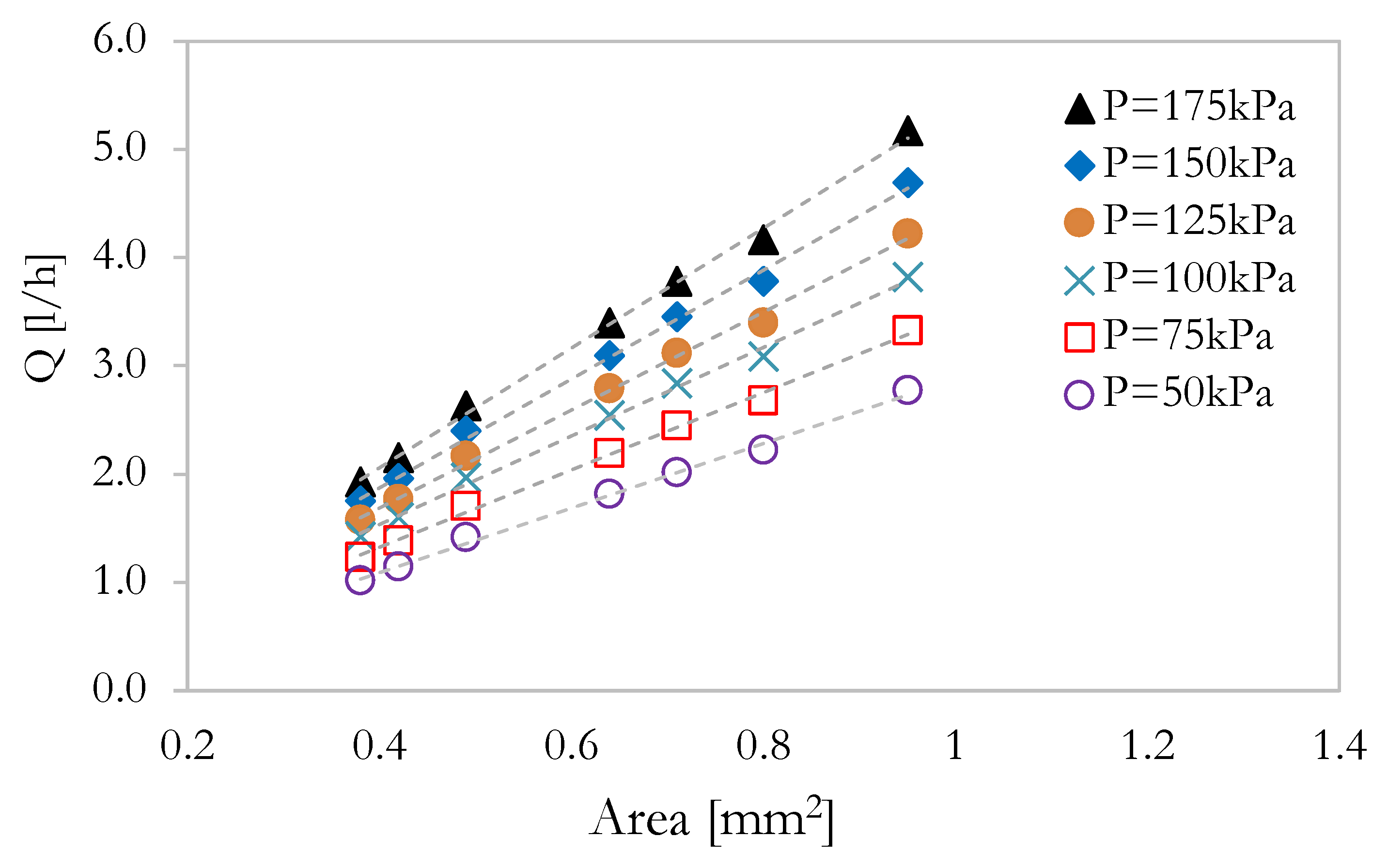
3.2. Flow Rate and Cross-Section Area Relation

In order to further investigate on the relation between the labyrinth area A and the flow rate q, in Figure 5, the emitter discharge is plotted against the transverse area A. The trend is clearly linear, and the data are well interpolated by a classical linear equation given by
q = α · A β
where α and β are coefficients that are different for each case. In Table 4, the achieved values are reported for reference.
The linearity behavior, shown above, represents a guide for the emitter design. It fact, it is possible to estimate the emitter flow rate once the drip area A is chosen, at least for the proposed labyrinth. The data presented in Figure 4 and Figure 5 serve as a guide for optimizing agricultural water distribution networks. Specifically, the selection of emitter geometry can be tailored to the required flow rate at each irrigation point, thereby minimizing the necessary pressure and, consequently, reducing pumping costs. For example, a flow rate of 2 L/h can be achieved with a low pressure of 75 kPa using a transverse cross-sectional area of 0.7 mm2. This approach enables the design of water distribution network (WDN) management strategies that consider both energy efficiency and economic feasibility. To mitigate clogging issues, the inlet pressure can be increased through pumping systems, enhancing the flow rate within the labyrinth channel.
Numerical results are typically validated using analytical data, when available, or by comparison with experimental results. In this case, the validation step has been omitted, as the numerical model and procedure have already been extensively validated in similar geometries (see, among others, refs. [25,26]). Moreover, one of the main advantages of CFDs is its ability to reduce design costs. Through numerical simulation, the optimal configuration can be determined, thereby lowering the manufacturing costs of the drip prototype. Once the optimal configuration is identified, experimental testing can be conducted.

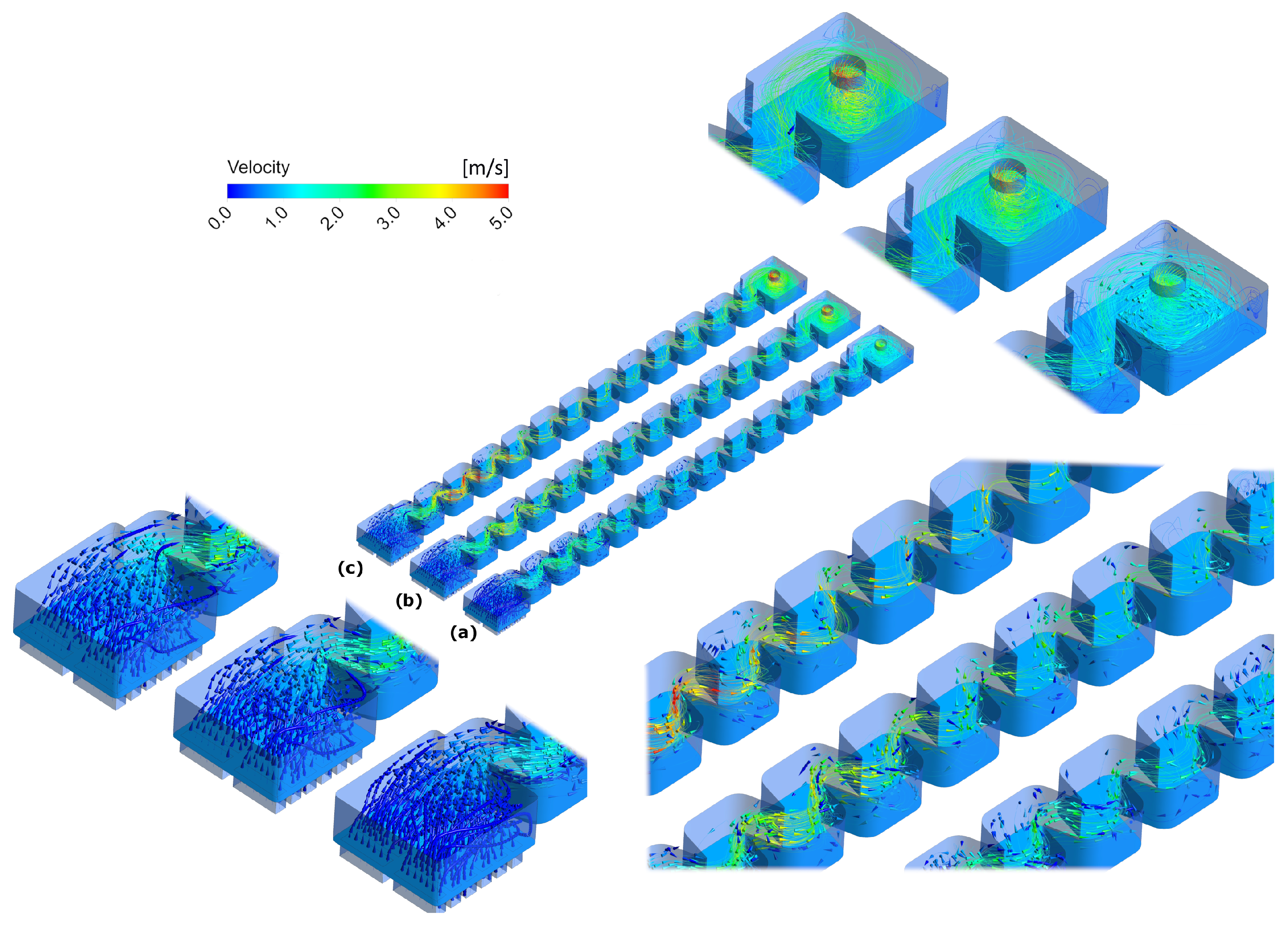
3.3. Velocity Field Analysis

On the basis of the above results, it is evident that the structural parameters of the flow channel have crucial influence on the internal flow characteristics and, more generally, on the emitter performance. The transverse area A clearly affects the discharge, and this is influenced by the velocity fields within the labyrinth. In order to further investigate on this issue, CFDs can also help having a clear visualization of the flow pattern. In Figure 6, the streamlines are depicted and colored as functions of the velocity field. Two main regions can be identified. The first zone is occupied by the mainstream and is characterized by high-speed values. The second region, conversely, is located outside the mainstream, within the labyrinth tooth, and it is identified by negative velocities given by huge eddies.
In Figure 6, three of the seven simulated cases are depicted. Specifically, in the top panels, Case 1 is shown. In the central panels, Case 4 is reported, whereas in the lower panels, the velocity contour and streamlines for the Case 7 are depicted. In all cases, the picture displays a complex flow pattern, with alternating regions of acceleration and deceleration caused by the serpentine structure of the labyrinth. The main stream is characterized, in fact, by a meandering behavior given by the toothed labyrinth shape. Otherwise, in the external region, wide recirculating regions are verified. The recirculation regions appear larger and more pronounced, particularly at the bends, for Case 7. This may indicate greater energy losses due to flow separation caused by sharper or more abrupt changes in channel design. The results are coherent with the quantitative analyses of the flow rate reported above. As pointed out by some recent research works (see, among others, ref. [19] and the literature cited therein), accurate prediction of the flow characteristics and understanding of the parameters affecting biofilm growth and particle deposition are crucial for effective anti-clogging strategies. In this framework, increasing flow velocity and optimizing labyrinth channel dimensions can effectively minimize sediment deposition, consequently enhancing the anti-clogging performance of the emitter. Looking at the velocity field depicted in Figure 6, it can be argued that the transverse area A affects the formation vortex region. This is mainly due to the enhancement of the meandering shape of the main stream. This behavior ensures more efficiency of the labyrinth in terms of anti-clogging. Specifically, examining the velocity field depicted in Figure 6, it can be observed that increasing the transverse area A leads to a reduction in the vortex region. This effect is primarily due to the improved meandering of the main flow, which improves the efficiency of the labyrinth in terms of anti-clogging. In the context of emitter clogging, it is essential to consider low-velocity regions near the channel walls, where the flow decelerates. These regions play a major role in clogging, exerting the most significant impact. The issue of low-velocity zones has been extensively studied in the literature [33], as the performance of drip irrigation systems is highly dependent on the flow field within the labyrinth. The data presented in Figure 6 indicate that Case 1 and Case 7 exhibited the largest recirculating regions in the outer sections of the labyrinth. Conversely, Figure 6c,d reveal a different behavior for the intermediate Case 4, where small unstable swirling zones were observed. This specific flow pattern may play a crucial role in the anti-clogging process, potentially enhancing emitter performance. However, the specific behavior of Case 4 is consistent with the data reported in Table 3, where it is possible to observe that the lowest exponent value x was achieved for Case 4. This result seems to guide the choice of the optimal shape of the emitter.
To better investigate the effect of pressure on the hydrodynamics within the drip emitter, a 3D flow field is presented. Specifically, Figure 7 shows the streamlines and velocity vectors for three different pressure conditions: (a) 50 kPa, (b) 100 kPa, and (c) 150 kPa. The results are shown for Case 4, although similar trends can be extended to the other simulated cases. The figure includes three panels, each providing an enlarged view of the inlet region, the outer region, and the central part of the labyrinth. The figure confirms that increasing pressure results in a higher mean velocity within the serpentine channel. In addition, the velocity decreases from the inlet to the outlet, highlighting the dissipative effect of the shape of the tooth. The flow exhibits turbulent behavior, particularly in the outlet region, where a large recirculating flow is observed. This complex three-dimensional turbulent motion plays a significant role in the anti-clogging mechanism.
Further analysis is necessary to gain deeper insights into the performance of drip irrigation systems. In fact, the optimal procedure to investigate on the emitter efficiency is to perform long-term stability tests. Through experimental campaigns, the change in flow rate, the change in pressure loss, and the possible emission clogging situation after continuous operation for a certain period of time can be examined; the structural integrity and performance stability can be evaluated, and the flow rate change can be analyzed for cycle maintenance determination.

4. Conclusions

The increasing demand for high-performance dripping hoses in agricultural irrigation highlights the need for accurate design methodologies and advanced fluid dynamic simulations. In this study, CFDs techniques were applied as an effective approach to analyze and optimize the hydrodynamic performance of drip emitters. This study primarily examined how variations in the cross-sectional area A affect the flow rate within the emitter.
The results confirm that designing emitters with a flow exponent value below 0.5 is critical for reducing water dispersion and facilitating the design of efficient irrigation systems. This optimal flow exponent is closely linked to the labyrinth channel geometry and its structural features, such as the configuration of the teeth. Seven different geometries were simulated, increasing the cross-sectional area, and for each emitter shape, six different pressure values, in the range of 50–175 kPa, were simulated. In all cases, flow exponent values below 0.5 were achieved, emphasizing the robustness of the proposed design approach. Moreover, the established relationship between the cross-sectional geometry of the labyrinth channel and the flow rate serves as a valuable foundation for designing future emitters tailored to varying flow rate requirements. In fact, a linear increase in outlet the flow rate was observed when increasing the cross-sectional area. These findings underscore the importance of coupling geometric optimization with computational fluid dynamics for the development of more efficient and reliable irrigation systems, meeting the demands of modern agriculture while conserving vital water resources. Among the simulated cases, it was possible to individuate an optimal geometric cross-section characterized by the lowest discharge exponent and by lower vortex regions, suggesting the best anti-clogging efficiency.

Author Contributions

All the authors contributed to the conceptualization, methodology, software, validation, and writing—original draft preparation. All authors have read and agreed to the published version of the manuscript.

Funding

This research received no external funding.

Data Availability Statement

Data available on request to the corresponding author.

Conflicts of Interest

The authors declare no conflicts of interest.

References

  1. Saccone, D.; De Marchis, M. Optimization of the design of labyrinth emitter for agriculture irrigation using computational fluid dynamic analysis. In Proceedings of the AlP Conference Proceedings, Thessaloniki, Greece, 14–18 March 2018; AlP Publishing LLC: Atlanta, GA, USA, 2018; Volume 2040, No. 1. p. 140013. [Google Scholar]
  2. De Marchis, M.; Milici, B.; Freni, G. Pressure-discharge law of local tanks connected to a water distribution network: Experimental and mathematical results. Water 2015, 7, 4701–4723. [Google Scholar] [CrossRef]
  3. Bruno, F.; De Marchis, M.; Milici, B.; Saccone, D.; Traina, F. A pressure monitoring system for water distribution networks based on arduino microcontroller. Water 2021, 13, 2321. [Google Scholar] [CrossRef]
  4. De Marchis, M.; Milici, B. Leakage Estimation in Water Distribution Network: Effect of the Shape and Size Cracks. Water Resour. Manag. 2019, 33, 1167–1183. [Google Scholar] [CrossRef]
  5. Yurdem, H.; Demir, V.; Mancuhan, A. Development of a simplified model for predicting the optimum lengths of drip irrigation laterals with coextruded cylindrical in-line emitters. Biosyst. Eng. 2015, 137, 22–35. [Google Scholar] [CrossRef]
  6. Li, Y.; Li, G.; Qiu, X.; Wang, J. Modeling of hydraulic characteristics through labyrinth emitter in drip irrigation using computational fluid dynamics. Trans. CSAE 2005, 21, 3. [Google Scholar]
  7. Wang, W.; Wang, F.; Zhao, F. Simulation of unsteady flow in labyrinth emitter of drip irrigation system. In Computers in Agriculture and Natural Resources, 4th World Congress Conference Proceedings; American Society of Agricultural and Biological Engineers: St. Joseph, MI, USA, 2006. [Google Scholar]
  8. Zhang, J.; Zhao, W.; Wei, Z.; Tang, Y.; Lu, B. Numerical and experimental study on hydraulic performance of emitters with arc labyrinth channels. Comput. Electron. Agric. 2007, 56, 120–129. [Google Scholar] [CrossRef]
  9. Zhao, W.; Zhang, J.; Tang, Y.; Wei, Z.; Lu, B. Research on transitional flow characteristics of labyrinth channel emitter. In Computer and Computing Technologies in Agriculture II, Volume 2; Springer: Boston, MA, USA, 2008. [Google Scholar]
  10. Wang, L.; Wei, Z.; Deng, T.; Tang, Y. Step-by-step CFD design method of pressure compensating emitter. Trans. Chin. Soc. Agric. Eng. 2012, 28, 86–92. [Google Scholar]
  11. Wei, Z.; Cao, M.; Liu, X.; Tang, Y.; Lu, B. Flow Behaviour Analysis and Experimental Investigation for Emitter Microchannels. Chin. J. Mech. Eng. 2012, 25, 729–737. [Google Scholar] [CrossRef]
  12. Celik, H.K.; Karayel, D.; Lupeanu, M.E.; Rennie, A.E.W.; Akinci, I. Determination of head losses in drip irrigation laterals with cylindrical in-line type emitters through CFD analysis. Bulg. J. Agric. Sci. 2015, 21, 703–710. [Google Scholar]
  13. Souza, W.J.; Sinobas, L.R.; Sánchez, R.; Botrel, T.A.; Coelho, R.D. Prototype emitter for use in subsurface drip irrigation: Manufacturing, hydraulic evaluation and experimental analyses. Biosyst. Eng. 2014, 128, 41–51. [Google Scholar] [CrossRef]
  14. Liu, X.; He, X.; Zhang, L. Simplified method for estimating discharge of microporous ceramic emitters for drip irrigation. Biosyst. Eng. 2022, 219, 38–55. [Google Scholar] [CrossRef]
  15. Liu, X.; Zhang, L.; Sun, Y.; Tong, X.; He, X.; Wei, Y. A novel variable discharge emitter for irrigation and salt-leaching. Biosyst. Eng. 2024, 246, 178–182. [Google Scholar] [CrossRef]
  16. Chen, X.; Wei, Z.; Wei, C.; He, K. Effect of compensation chamber structure on the hydraulic performance of pressure compensating drip emitters. Biosyst. Eng. 2022, 214, 107–121. [Google Scholar] [CrossRef]
  17. Li, H.; Li, P.; Li, J.; Jiang, Y.; Huang, X. Influence of micro/nano aeration on the diversity of the microbial community in drip irrigation to reduce emitter clogging. Biosyst. Eng. 2023, 235, 116–130. [Google Scholar] [CrossRef]
  18. Yang, B.; Wang, F.; Wang, J.; Wang, C.; Qiu, X. Numerical simulation and optimisation of the inlet structure of dentiform emitters in drip-irrigation systems. Biosyst. Eng. 2024, 246, 183–190. [Google Scholar] [CrossRef]
  19. Dallagi, H.; Ait-Mouheb, N.; Soric, A.; Boiron, O. Simulation of the flow characteristics of a labyrinth milli-channel used in drip irrigation. Biosyst. Eng. 2024, 239, 114–129. [Google Scholar] [CrossRef]
  20. Senyigit, U.; Cruz, R.L.; Rodriguez-Sinobas, L.; Souza de Jesus, W. Changes on emitter discharge under different water temperature and pressure. J. Food Agric. Environ. 2012, 10, 718–720. [Google Scholar]
  21. Senyigit, U.; Ilkhan, M.S. The effects of water temperature on discharge and uniformity parameters of emitters with different discharges, types and distances. Tarim Bilim. Derg. 2017, 23, 223–233. [Google Scholar]
  22. Lv, C.; Niu, W.; Du, Y.; Sun, J.; Dong, A.; Wu, M.; Mu, F.; Zhu, J.; Siddique, K.H.M. A meta-analysis of labyrinth channel emitter clogging characteristics under Yellow. River water drip tape irrigation. Agric. Water Manag. 2024, 291, 1–10. [Google Scholar] [CrossRef]
  23. Li, C.; Li, Z.; Du, P.; Ma, J.; Li, S. Mechanism Analysis of the Influence of Structural Parameters on the Hydraulic Performance of the Novel Y-Shaped Emitter. Agriculture 2023, 13, 1160. [Google Scholar] [CrossRef]
  24. Li, Y.; Feng, X.; Han, X.; Sun, Y.; Li, H. Machine Learning Approach to Predict Flow Regime Index of a Stellate Water-Retaining Labyrinth Channel Emitter. Agronomy 2023, 13, 1063. [Google Scholar] [CrossRef]
  25. Li, Y.; Feng, X.; Han, X.; Sun, Y.; Liu, Y.; Yao, M.; Liu, H.; He, Q.; Li, H. Analysis of internal flow characteristics and determination of the core structural parameters of a stellate labyrinth channel irrigation emitter. Biosyst. Eng. 2023, 231, 1–19. [Google Scholar] [CrossRef]
  26. Qiu, X.; Chen, G.; Wang, H.; Wang, C.; Wang, J. Vertical optimisation of tooth shape to improve the anti-clogging performance of emitters in drip irrigation systems. Biosyst. Eng. 2023, 233, 193–203. [Google Scholar] [CrossRef]
  27. Li, Y.; Feng, X.; Liu, Y.; Han, X.; Liu, H.; Sun, Y.; Li, H.; Xie, Y. Research on Hydraulic Properties and Energy Dissipation Mechanism of the Novel Water-Retaining Labyrinth Channel Emitters. Agronomy 2022, 12, 1708. [Google Scholar] [CrossRef]
  28. Seo, B.S.; Lee, S.; Lee, J.H.; Kim, D.S.; Seo, Y.J.; Kim, D.W.; Choi, W. Efficient two-way fluid–structure interaction simulation for performance prediction of pressure-compensating emitter. Biosyst. Eng. 2024, 244, 53–66. [Google Scholar] [CrossRef]
  29. von Westarp, S.; Chieng, S.; Schreier, H. A comparison between low-cost drip irrigation, conventional drip irrigation, and hand watering in Nepal. Agric. Water Manag. 2004, 64, 143–160. [Google Scholar] [CrossRef]
  30. Chamba, D.; Zubelzu, S.; Juana, L. Energy, cost and uniformity in the design of drip irrigation systems. Biosyst. Eng. 2019, 178, 200–218. [Google Scholar] [CrossRef]
  31. ISO 9261; Agricultural Irrigation Equipment, Emitters and Emitting Pipe, Specification and Test Methods. ISO: Geneva, Switzerland, 2004.
  32. ANSYS Inc. ANSYS 2024 User Guide; ANSYS Inc.: Canonsburg, PA, USA, 2024; Available online: https://www.ansys.com (accessed on 24 February 2025).
  33. Li, Y.; Yang, P.; Xu, T.; Ren, S.; Lin, X.; Wei, R.; Xu, H. CFD and digital particle tracking to assess flow characteristics in the labyrinth flow path of a drip irrigation emitter. Irrig. Sci. 2008, 26, 427–438. [Google Scholar] [CrossRef]
Figure 1. Schematic representation of the drip irrigation emitter.
Water 17 00689 g001
Figure 2. Geometrical cross-section shape and related parameters.
Water 17 00689 g002
Figure 3. Computational mesh.
Water 17 00689 g003
Figure 4. Discharge–pressure curves for the simulated cases. ◯: Case 1; □: Case 2; ✕: Case 3; •: Case 4; ♦: Case 5; ▲: Case 6; ◼: Case 7.
Water 17 00689 g004
Figure 5. Flow rate vs cross-section area A of the labyrinth channel.
Water 17 00689 g005
Figure 6. Velocity contour and mean streamlines for the Cases 1, 4, and 7. The streamlines are colored as functions of the velocity. Blue is lower values, and red is higher velocities. (a): Velocity contour for Case 1; (b): Velocity streamlines for Case 1; (c): Velocity contour for Case 4; (d): Velocity streamlines for Case 4; (e): Velocity Contour for Case 7; (f): Velocity streamlines for Case 7.
Water 17 00689 g006
Figure 7. Three-dimensional flow field for Case 4 under three different pressure conditions: (a) 50 kPa; (b) 100 kPa; (c) 150 kPa. Streamlines and vectors are depicted as functions of the velocity module.
Water 17 00689 g007
Table 1. Channel cross-section geometrical parameter.
CaseWidth L [mm]Height h [mm]Area A [mm2]
10.630.600.378
20.650.650.422
30.700.700.490
40.800.800.640
50.840.850.714
60.890.900.801
71.000.950.950
Table 2. Flow rate q as function of the inlet pressure P.
Pressure [kPa]
5075100125150175
Case Flow Rate
q [L/h]
11.01001.22711.42401.57281.75001.9272
21.14201.38291.60101.76251.95602.1495
31.41601.70471.96502.16092.39602.6312
41.81202.19262.53702.78863.09103.3934
52.01302.44412.83503.11323.44803.7829
62.22002.67223.08003.39923.78004.1608
72.77403.32623.82304.22034.69405.1677
Table 3. Discharge k and exponent x coefficients for the simulated cases.
Casexk
10.49900.1450
20.49860.1613
30.49450.2079
40.48830.2601
50.49720.2864
60.49520.3166
70.49040.4025
Table 4. α and β coefficients.
Case α β
15.540.158
25.030.139
34.520.119
44.090.102
53.570.104
62.980.105
Disclaimer/Publisher’s Note: The statements, opinions and data contained in all publications are solely those of the individual author(s) and contributor(s) and not of MDPI and/or the editor(s). MDPI and/or the editor(s) disclaim responsibility for any injury to people or property resulting from any ideas, methods, instructions or products referred to in the content.

