Abstract
In coal seam mining operations, the presence of overlying water bodies presents persistent challenges, particularly during multi-seam extraction, where water accumulation in upper seam goafs requires careful management. This study examined the Lingzhida Coal Mine, focusing on the geological conditions of the 3# seam (upper) and the 15# seam (lower), as well as the distribution of water accumulation in the corresponding goafs. The mechanism of water inrush from the upper goaf was studied, and the role of the water-resisting belt (WRB) is suggested. By utilizing empirical equations and field measurements, a method for calculating the floor fracture depth of the 3# seam and the roof fracture height of the 15# seam was derived through multi-linear regression analysis. Based on the relationship between the thickness of the WRB (Hw) and the protective layer (Hp), a classification criterion for the water-inrush risk (the likelihood of water entering the lower seam from the upper goaf) is proposed. The mining area was divided into four risk zones: high-risk (Hw < 0), medium-risk (0 ≤ Hw < 0.5Hp), low-risk (0.5Hp ≤ Hw < Hp), and safe (Hw ≥ Hp). Then, an adaptive zoning approach for water-preserved mining was introduced, considering the spatial distribution of goaf water. This approach incorporates water-preserved mining technologies, including the staggered layout of working faces, reduction in mining height, and the transfer–storage of water resources. These research findings provide crucial insights for ensuring the safe and efficient extraction of the multi-seam.
1. Introduction
The goaf of an upper coal seam group is highly susceptible to the accumulation of substantial amounts of water, which presents a significant threat to the safe mining of the underlying coal seams [1,2]. According to statistics, over 70% of permeability accidents in mines are attributed to water accumulation in the goaf areas [3,4]. A notable example occurred on 29 November 2020, at the Yuanjiangshan Coal Mine (Yuanjiangshan Coal Industry Co., Ltd.; Hengyang, China), where a major water-inrush accident resulted in 13 fatalities. The cause was traced to the accumulation of water in the upper section of the −350 m goaf during mining of the 61 coal seam at the −500 m level [5]. Similarly, on 10 April 2021, a major water leakage accident at the Fengyuan Coal Mine (Xinjiang Agricultural Sixth Division Coal and Electricity Co., Ltd.; Changji, China) led to 21 deaths. The incident was triggered by the excavation of the B4W01 return airway, which unintentionally connected with the old goaf water from the adjacent Baiyangshu Coal Mine [6]. On 1 June 2024, a water-related accident occurred at the Huafeng coal mine (Shandong Energy Xinwen Mining Group Co., Ltd.; Taian, China), resulting in three deaths. The cause was the accumulation of water in the 11,105 goaf during mining operations at the 11,106 working face [7]. These incidents highlight the critical need for research focused on the safe mining of coal seams in conditions where water accumulation in the goaf poses a risk.
Numerous studies have been conducted on the mechanism of roof water inrush, yielding significant results [8]. However, the interlayer rock formations in coal seam groups, which are subjected to repeated mining disturbances from both the upper and lower coal seams, present a more complex situation compared to traditional single-seam mining [9]. Research on the roof water-inrush mechanism during coal seam mining typically focuses on three key aspects, as follows. (1) The first is utilization of the “upper and lower three zones” theory to calculate the depth of the floor fracture in the upper coal seam post-mining and the height of the roof fracture in the lower coal seam post-mining and determination of whether these fractures would connect [10,11]. (2) Based on the “key stratum” theory, it is essential to determine the existence of a water barrier [12,13] or key layer [14,15] between the upper and lower coal seams and to establish an appropriate mechanical model to assess whether this barrier or key layer is compromised following the extraction of the lower coal seam. (3) Based on the theory of fuzzy mathematics and considering the influence of factors such as the mining height, interlayer spacing, and lithology, a predictive model for overlying water inrush is established. Various methods have been proposed, including the fuzzy comprehensive evaluation method [16], gray theory method [17], neural network method [18], expert system method [19], multi-information fitting method [20], and the three-graph-double prediction method [21]. The proposed water-inrush index is used to assess the likelihood of water inrush based on its numerical range, enabling the determination of whether water inrush will occur.
The research on the prevention and control technology of roof water inrush can be divided into two categories: (1) changing the mining process to reduce the disturbance to the overlying water body, such as reducing the mining height [22], shortening the length of the working face [23], and backfilling mining [24]; and (2) adopting relevant technologies to reduce the impact of roof water inrush on the mining of the lower coal seam working face, such as drilling drainage [25] and grouting sealing [26].
Based on a comprehensive analysis of the existing literature, two main issues have been identified. (1) The relationship between the mining of the lower coal seam and water accumulation in the goaf of the upper coal seam is typically determined qualitatively, often based on whether the interlayer rock fractures are conductive. However, there is a lack of zoning, grading, and quantitative evaluation of the entire mining area, which limits a more precise understanding of the water flow dynamics across different regions. (2) The treatment of water accumulation in the goaf generally relies on drilling drainage technology. However, this method is often not supported by a pre-designed system-wide perspective that takes into account the entire mining layout. Additionally, there is a lack of active control over the water resistance performance of mining rock layers, which can lead to suboptimal drainage and risk management. This article uses Lingzhida Coal Mine as a case study to analyze the relative relationship between the floor fracture depth of the 3# seam, the roof fracture height of the 15# seam, and the thickness of the protective layer. A standard for evaluating the inrush degree of goaf water is formulated, which divides the 15# seam into four risk zones: high-risk, medium-risk, low-risk, and safe. Based on the distribution of accumulated water in the goaf, adaptive zoning for water-preserved mining is proposed, categorizing areas into pre-drained, water-preserved, and normal mining zones. Additionally, auxiliary technologies for water-preserved mining are suggested to ensure the safe mining of the 15# seam.
2. Geological Conditions of the Study Area
2.1. Coal Seam Conditions
The main coal seams in Lingzhida Coal Mine are 3# and 15#, with the 3# seam having a thickness of 0–5.5 m and an average of 3.1 m, which is the upper coal seam studied in this work. The 15# seam has a thickness of 0.7–7.2 m with an average of 4.0 m, and is currently being mined [23]. The mine is divided into east and west parts by the Zhuangtou fault, with the I, II, and V mining districts being the main mining areas, as shown in Figure 1.
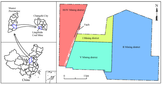
Figure 1.
Geographical location of Lingzhida Coal Mine.
2.2. Goaf Water Distribution in the Upper Coal Seam
According to preliminary exploration, there are currently 19 goaf water areas in the 3# coal seam, with an estimated area of about 64 × 104 m2, as depicted in Figure 2 [23].
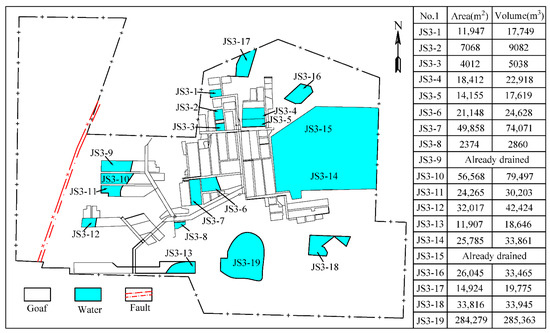
Figure 2.
Goaf water distribution in the Lingzhida Coal Mine.
2.3. Geological Conditions of the Interlayer Rock Strata
The distance between the 3# coal seam and 15# coal seam is 92.1–138.7 m, with an average of about 106 m (Figure 3). The interlayer strata are mainly limestone, mudstone, and sandstone, in which limestone and sandstone are aquifers, and mudstone is aquiclude.
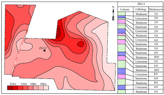
Figure 3.
Geological column of the interlayer strata between the 3# and 15# coal seams.
3. Water-Inrush Mechanism of the Overlying Goaf
The water-conducting fracture formed by the mining of the 15# seam may lead to the goaf in the 3# seam in some sections such that the water in the goaf of the 3# seam could pour into the 15# seam face.
3.1. Water-Inrush Analysis during Lower Coal Seam Mining
According to the fracture connectivity of the interlayer strata after upper and coal seam mining, the multi-seam can be classified into three types: primary connectivity, secondary connectivity, and unconnected.
- Primary connectivity type
Here, the sum of the initial depth of the floor fracture zone after mining the upper coal seam and the roof fracture zone after mining the lower coal seam is greater than or equal to the thickness of the interlayer strata. At this point, the fractures are fully connected. Water from the upper coal seam goaf will flow directly into the lower coal seam working face, causing the interlayer rock layer to lose its water resistance completely (Figure 4).
Here, Hc represents the thickness of the interlayer strata between the upper and lower coal seams, m; Hf represents the depth of the floor fracture zone after the upper seam is mined, m; and Hr represents the height of the roof fracture zone after the lower seam is mined, m.
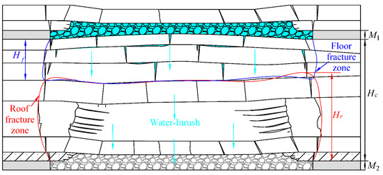
Figure 4.
Multi-seam primary connectivity.
- Secondary connectivity type
Here, the sum of the initial depth of the floor fracture zone and the roof fracture zone is less than the thickness of the interlayer strata. However, mining the lower coal seam induces secondary fracture development in the floor of the upper coal seam, increasing the depth of the floor fracture zone. As a result, the combined depth of the secondary developed floor fracture zone and the roof fracture zone becomes greater than or equal to the thickness of the interlayer strata (Figure 5). This situation also leads to water from the upper coal seam goaf flowing into the lower seam.
Here, Hf−2 represents the secondarily developed depth of the floor fracture zone, m.
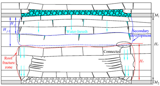
Figure 5.
Multi-seam secondary connectivity.
- Unconnected type
Here, if the combined secondary development depth of the floor and roof fracture zones is less than the thickness of the interlayer strata, the interlayer still retains a certain thickness of intact strata (Figure 6). However, the question of whether the accumulated water in the goaf of the upper coal seam could flow into the working face of the lower coal seam must be determined based on the thickness of the retained intact strata.
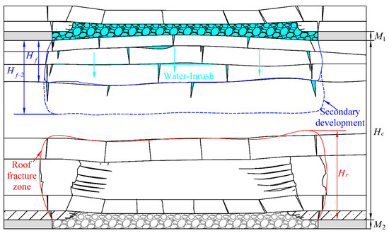
Figure 6.
Unconnected multi-seam.
3.2. Depth of the Floor Fracture after Upper Seam Mining
According to the technical specifications, the calculation equation of the floor fracture depth can be expressed as [27]:
where Hf1, Hf2, and Hf3 all represent the depth of the floor fracture according to different engineering conditions, m; Hm represents the buried depth of the coal seam, m; θ represents the dip angle of the coal seam, °; and L represents the inclined length of the coal seam, m.
According to Equation (4), the depth of the floor fracture is mainly related to factors such as the coal seam burial depth, the working face inclination length, and the coal seam dip angle.
- The observed data of mining areas with similar geological conditions
Due to the lack of consideration of mining height factors when calculating the depth of the floor fracture zone in Equation (4), we collected data on the depth of floor failure in coal mines under similar geological conditions as data samples (Table 1) and added the mining height factors to fit the formula for calculating the depth of the floor fracture in Lingzhida Coal Mine.

Table 1.
Observed data of mining areas with similar geological conditions.
- Multiple linear regression of floor fracture depth
The influencing factors of the floor fracture depth in the original empirical Equation (4) were increased from three to four, with mining height considered. The linear equation was established as follows:
where Hf represents the depth of the floor fracture, m; Hm represents the buried depth of the coal seam, m; θ represents the dip angle of the coal seam, °; M represents the mining height, m; and L represents the inclined length of the working face, m.
The observed data of the floor fracture depth, shown in Table 1, were imported into Origin software, and linear regression analysis between the floor fracture depth and the mining height was conducted. The fitting curve is shown in Figure 7.
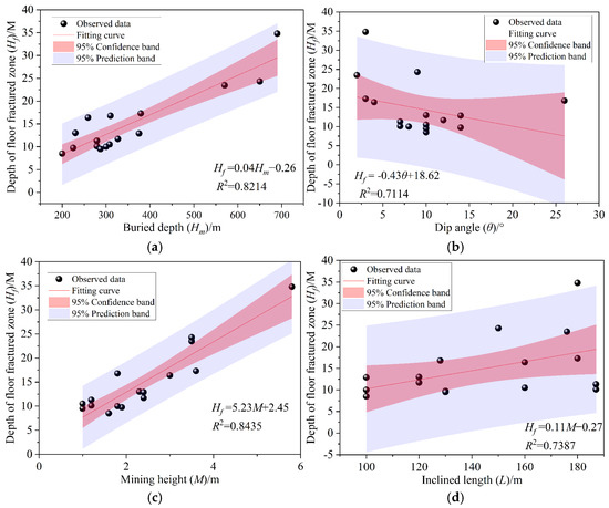
Figure 7.
The relationship between the influent factors and the depth of the floor fracture. (a) Buried depth. (b) Dip angle. (c) Mining height. (d) Inclined length.
Figure 7 indicates there was a high degree of fitting between the buried depth, mining height, dip angle, inclined length, and the depth of the floor fracture. The specific results of various parameter indicators in the linear regression equation are shown in Table 2. Considering the depth of the floor fracture after mining, the linear regression equation is:
Table 2.
Results of linear regression calculation.
According to Table 2, the correlation coefficient R2 = 0.9610 and the multiple correlation coefficient R = 0.9800 were close to 1, indicating a high degree of correlation between the depth of the floor fracture and the variables in Equation (6). The ratio of the regression mean square to the residual mean square F = 74.3630 and the probability value p = 0.0001 in the statistical coefficients meet the requirements, and the regression effect was significant.
Through the contour map of the 3# coal seam thickness and the mining plane map, the relevant parameters such as the mining height, mining depth, and working face length corresponding to each point were calculated. Equation (6) was used to calculate the floor fracture depth, and the results are shown in Table 3.
Table 3.
The calculated results of the maximum floor fracture depth of 3# coal seam.
According to Table 3, the maximum floor fracture depth caused by the mining of the 3# coal seam in the I, II, and V mining districts was 22.22 m, 21.47 m, and 20.83 m, respectively.
3.3. Height of the Roof Fracture after Lower Seam Mining
The roof fracture height formed after mining a coal seam is a crucial factor for the successful implementation of roof water hazard prevention and control [28,29]. This section is based on the observed data of the roof fracture height in Lingzhida Coal Mine, as well as similar geological conditions. The calculation equation for the roof fracture height applicable to this mine was derived and then compared and analyzed with the empirical calculation equation provided in the technical specifications.
- Observed data of mining areas with similar geological conditions
The observed data of the roof fracture height in Lingzhida Coal Mine and similar geological conditions mines were collected as reference materials for this study area, as shown in Table 4 and Table 5, respectively.
Table 4.
Observed data of the roof fracture height in Lingzhida Coal Mine.
Table 5.
Observed data of the roof fracture height in mines with similar geological conditions.
- Multiple linear regression of the roof fracture height
Based on the traditional empirical equation between the mining thickness and the roof fracture height, a multiple linear regression method was used to fit the functional relationship applicable to Lingzhida Coal Mine. A commonly used equation for calculating the roof fracture height is [28]:
where Hr represents the height of the roof fracture, m; M represents the mining height, m; and a and b represent the coefficient related to the mine’s geological conditions.
Based on the observed data of the roof fracture height in Lingzhida Coal Mine and adjacent mines with similar geological conditions, this study conducted regression analysis on parameters a and b in Equation (7), as follows:
In Equation (8), there is a linear relationship between 1/Hd and 1/M. The fitting of the relationship is shown in Figure 8.
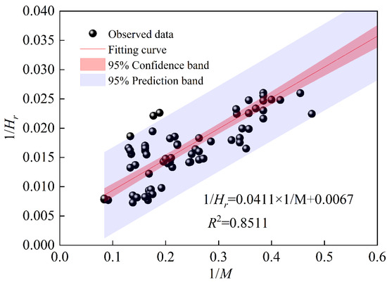
Figure 8.
The relationship between 1/Hr and 1/M.
According to Figure 8, Equation (8) can be expressed as:
The empirical calculation equations of the roof fracture height are listed in Table 6. The average thickness of the 15# coal seam in Lingzhida Coal Mine is 4.2 m, and the roof belongs to the hard rock strata. The height of the roof fracture in Lingzhida Coal Mine calculated by the empirical equations and the linear regression Equation (9) is shown in Table 7.
Table 6.
Empirical equations of the roof fracture height [28].
Table 7.
Calculated results of empirical and linear regression equations.
According to Table 7, the roof fracture height calculated by the linear regression equation was smaller than that obtained by the empirical equation. The main reason was that the observed data were measured several months or even years after coal mining, when the movement of the overlying strata tends to be stable. Therefore, the observed values in Table 7 were generally smaller. Considering the safety of coal mining, the envelope method was used to revise the linear regression equation, and the modified results are shown in Figure 9.
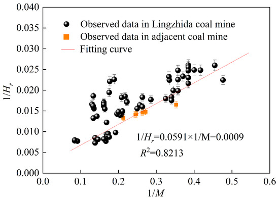
Figure 9.
The relationship between 1/Hr and 1/M after modification.
According to Figure 9, the revised equation for calculating the roof fracture height is as follows:
The calculated result of the roof fracture height using the modified linear regression formula was 75.92 m, which was larger than the calculated result of the empirical equation. In Figure 9, the blue dot is the observed value in similar geological conditions, and the yellow dot is the measured value of boreholes in the previously observed data in Lingzhida Coal Mine. The dots above the envelope line are much larger than those below the envelope line, indicating that the height data obtained by the modified linear regression equation by the envelope method were larger than most of the observed values. From a safety perspective, the modified linear regression equation was relatively reasonable.
The geological data of the 15# coal seam in Lingzhida Coal Mine were substituted into Equation (10) to calculate the maximum roof fracture height in the I, II, and V mining districts, as shown in Table 8.
Table 8.
Calculated results of the maximum roof fracture height of 15# coal seam.
According to Table 8, the maximum height of the roof fracture generated during the 15# coal seam mining in the I, II, and V mining districts was 63.65 m, 87.57 m, and 81.92 m, respectively.
4. Zoning Characteristics of Water-Inrush Risk and Water-Preserved Mining
4.1. Zoning Criteria
Whether the roof fracture of the 15# seam mining would connect to the overlying 3# goaf mainly depends on the thickness of the WRB between the upper and lower coal seams after mining. A simplified model of the interlayer strata is shown in Figure 10.
Here, Hw represents the residual intact strata (WRB) after the upper and lower seam mining, m; Hc represents the thickness of the interlayer strata between the upper and lower coal seams, m; Hf represents the depth of the floor fracture after the upper seam mining, m; and Hr represents the height of the roof fracture after the lower seam mining, m.
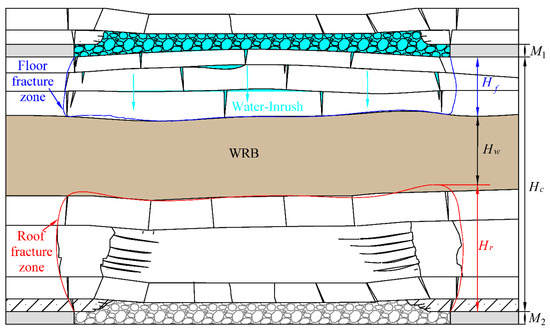
Figure 10.
Simplified model of the interlayer strata after upper and lower seam mining.
- If the thickness of the WRB Hw ≤ 0, the fracture would penetrate the interlayer strata between the upper and lower seams; that is, the water in the of the overlying 3# seam goaf would flow into the working face in the 15# seam.
- If the thickness of the WRB Hw > 0, the thickness of the protective layer Hp should also be considered. If the thickness of the WRB Hw is greater than the thickness of the protective layer Hp (Hw > Hp), the fracture will not penetrate the interlayer strata and the WRB has sufficient water-resisting capacity, which can block the water inflow of the overlying goaf. If the thickness of the WRB Hw is less than the thickness of the protective layer Hp (Hw ≤ Hp), the fracture will not penetrate the interlayer strata during the mining process, but the residual water-resisting capacity of the interlayer rock layer is insufficient, which may lead to the downward leakage of water in the goaf. Therefore, whether water inrush occurs in coal mining under water accumulation in the goaf mainly depends on the protective layer thickness Hp.
The thickness of the protective layer should be determined according to the geological and mining conditions of the mining area and the water resistance of the protective layer [27]. The thickness of the protective layer can be selected according to the technical specifications, as illustrated in Table 9.
Table 9.
Thickness of the protective layer resisting water.
In Lingzhida Coal Mine, the strata exhibit varying water resistance capabilities, so a generalized approach is not applicable. Based on the technical specifications and previous observational data, roof leakage was detected in the haulage roadway of the 15,102 working face. Therefore, it is more reasonable to consider 7A as the thickness of the protective layer.
Due to the secondary disturbance caused by the mining of the 15# coal seam, secondary fracturing is likely to occur in the previously mined 3# coal seam. Therefore, it is essential to assess the impact of goaf water on the mining of the lower coal seam based on the actual conditions and the required thickness of the protective layer. By using the actual interlayer thickness as the standard, the influence of lower coal seam mining on goaf water was divided into zones across the mining area. The zoning criteria are outlined in Table 10.
Table 10.
Zoning criteria of water inrush.
4.2. Zoning Characteristics of Water Inrush
- The distribution characteristics of WRB
Based on the calculated results of the floor fracture depth of the 3# coal seam and the roof fracture height of the 15# coal seam, combined with the interlayer strata thickness data, Surfer 20.1.195 software was used to draw the contour map of the WRB thickness after the upper and lower coal seams were mined, as shown in Figure 11.
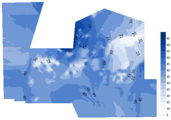
Figure 11.
The WRB thickness contour after the upper and lower coal seams were mined.
Figure 11 indicates that the thickness of the WRB ranges from 5 to 65 m, and the adjacent color legends are separated by 5 m. The lighter the color, the thinner the WRB.
- Risk zoning characteristics of 15# seam mining
According to the distribution of the WRB thickness in Figure 11 combined with the zoning criteria for the risk of water inrush in Table 2, a zoning map of the risk distribution of the 15# coal seam mining can be drawn, as shown in Figure 12.
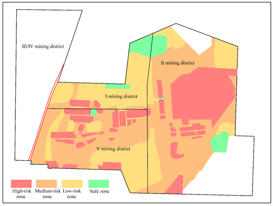
Figure 12.
The risk distribution of water inrush during 15# coal seam mining (note: the white part lacks effective drilling data, so it remains undetermined).
With the mining of the 15# coal seam, the high-risk zone of water inrush was mainly distributed in the northeast of the II and V mining districts. The WRB thickness in the 3616 goaf, 3618 goaf, and the small coal mine goaf indicates that the degree and scope of rock damage caused by mining in this area were significant, and the interlayer strata were relatively thin. Following the development of mining fractures, the residual water resistance of the interlayer strata weakened, leading to a higher risk of water inrush in the lower coal seam working face.
4.3. Zoning Characteristics of Water-Preserved Mining
Section 3.2 only analyzed the distribution characteristics of the WRB under repeated mining disturbance between the 3# and 15# coal seams, focusing on mining fractures without considering the water-bearing areas. Figure 12 illustrates the zoning characteristics of water inrush based on the residual water resistance of the WRB. However, the determination of residual water resistance under repeated mining disturbance of the WRB is only practically relevant in areas where water bodies exist above. Based on the distribution characteristics of goaf water shown in Figure 2, this section describes the evaluation of the safe mining conditions of the 15# coal seam, as depicted in Figure 13.
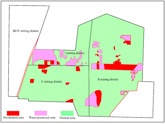
Figure 13.
The distribution of water-preserved mining.
In the pre-drained zone, the interlayer strata lack sufficient thickness of protective layers due to the combined effects of mining disturbances from both the upper and lower coal seams. The WRB’s capacity is insufficient, which may lead to fracture penetration and result in water inrush at the working face of the lower coal seam. Therefore, this area must strictly adhere to the relevant coal mine water prevention regulations, and advanced water exploration and drainage must be carried out.
In the water-preserved zone, the interlayer strata still retain 0 to 0.5 times the thickness of the protective layer after removing the fractured zone. The WRB in this area offers a certain degree of water resistance, but slight leakage from overlying water bodies may occur under mining disturbance. Therefore, appropriate water-preserved mining methods, such as the staggered layout of working faces or localized treatment techniques, should be adopted based on the extent of water leakage observed during mining operations in this area.
In the normal zone, the interlayer strata retain an intact protective layer thickness after removing the fractured zone. The WRB in this area provides sufficient water resistance, effectively preventing the downward leakage of overlying water during mining. Since there are no overlying water bodies in other areas, both zones can be mined normally.
5. Water-Preserved Mining Technologies
5.1. Mining Face Layout
The mining layout of the upper and lower coal seam working faces can be divided into two methods: internal and external staggered layouts for the lower coal seam [22,30]. According to the theory of surface subsidence basins, the overlying rock layers of coal seams can be regarded as “subsidence basins,” consisting of a flat undeformed area in the center of the basin and areas of stretching or compression deformation on both sides. The line connecting the moving boundary of the subsidence basin to the coal seam mining boundary is referred to as the moving boundary line. The line connecting the boundary of the flat undeformed area in the center of the basin to the coal seam mining boundary is called the fully mining line [31].
- Internal staggered layout
The maximum depth of the floor fracture is located at the boundary of both sides of the goaf, and the mining of the lower coal seam would cause the secondary development of the fracture [32]. However, as long as the moving boundary of the “WRB subsidence basins” is within the original range after the lower coal seam mining, secondary migration and damage would not occur at the boundary of the WRB.
The internal staggered layout of the lower coal seam is shown in Figure 14, and the critical internal staggered layout distance can be expressed as:
where Lnc represents the critical internal staggered layout distance, m; Lb represents the distance between the maximum depth point of the floor fracture and the coal wall (positive when measured inside the coal wall, negative when measured outside the coal wall), m; and α represents the moving angle of WRB, °.
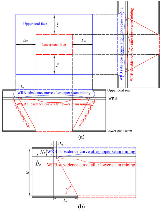
Figure 14.
Internal staggered layout of lower coal seam. (a) Planar and sectional graph of internal staggered layout. (b) Calculation model.
- External staggered layout
When the lower coal seam was arranged externally, as long as the damage area of the WRB was ensured to be in the non-deformation area in the middle of the subsidence basin after the mining of the lower coal seam, the fracture would not develop secondarily.
The external staggered layout of the lower coal seam is shown in Figure 15, and the critical external staggered layout distance can be expressed as:
where Lwc represents the critical external staggered layout distance, m; La represents the distance between the maximum outside point of the floor fracture and the coal wall, m; and β represents the fully mining angle of WRB, °.
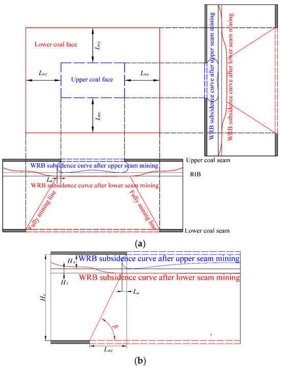
Figure 15.
External staggered layout of lower coal seam. (a) Planar and sectional graph of external staggered layout. (b) Calculation model.
5.2. Mining Height
The mining height of the lower coal seam directly affects the disturbance degree to the interlayer strata, and reducing the mining height could significantly reduce the development height of the roof fracture caused by lower coal seam mining [33,34]. The reduced mining height of the lower coal seam is shown in Figure 16.
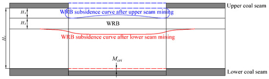
Figure 16.
Diagram of reducing the mining height.
Based on Equation (11) in Section 4.1, the calculation equation for the critical height of the roof fracture in the safe zone during lower coal seam mining can be obtained:
According to Equation (14), the critical mining height can be deduced:
Reducing the mining height can be used in conjunction with the internal and external staggered layout of the coal seam working face.
5.3. Water Transfer and Storage Technology
Currently, water-preserved mining is primarily categorized into two approaches. The first focuses on preventing water leakage through measures such as internal/external staggered layouts, reduced mining height, and backfilling mining techniques. The second approach involves directly discharging water from the aquifer to the goaf, using technologies such as underground goaf reservoirs. A new water-preserved mining technology based on groundwater transfer storage and goaf water storage has been proposed [35].
5.3.1. Location of Water Storage
- Water storage location in the upper seam
As a water storage space, the upper coal seam goaf needs to meet the following two conditions. First, the current water accumulation in the goaf should be relatively small, and there should be sufficient water storage space; second, the integrity of the rock layers in the goaf should be relatively good, thereby preventing water resource leakage. Reasonable location of water storage space is shown in Figure 17.
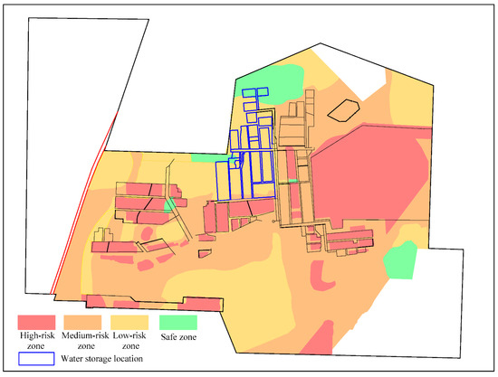
Figure 17.
Water storage location in the upper seam.
- Water storage location in the lower seam
The location of the lower coal goaf, as an underground water storage space, should not only meet the criteria for the upper coal goaf but also ensure the safety of the upper coal reservoir. Additionally, the location should be chosen in a low-lying area to allow mine water to be discharged to this area using potential energy from the height difference when mining the higher-lying coal. When constructing the reservoir in the lower coal seam, it is essential to ensure that the mining stress field and fracture field do not extend to the upper coal seam or the same-layer reservoir, preventing leakage from the underground reservoir in the upper coal seam. Based on these site selection criteria, the safe horizontal distance between the lower coal seam reservoir and the upper coal seam reservoir was determined. The selection results for the lower coal seam are shown in Figure 18.
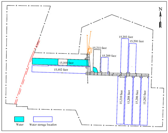
Figure 18.
Water storage location in the lower seam.
5.3.2. Technical Scheme of Water Resources Transfer and Storage
- Transfer and storage of water resources in the same layer
To address the mine water issues caused by the mining of the 15# seam, a thorough and accurate investigation of the surrounding water resource distribution should be conducted, followed by the development of a reasonable mining plan based on local conditions. The existing drainage system should be renovated, applying the principle of “connectors.” Utilizing geographical features, such as terrain differences, accumulated water in the goaf can be directed to underground reservoirs in low-lying areas with less accumulated water. This process should be facilitated through manual intervention and the installation of specific drainage pipelines. A three-dimensional schematic diagram of water regulation in the same-level underground reservoir is shown in Figure 19.
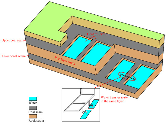
Figure 19.
Water transfer system in the same layer.
- Transfer and storage of water resources in a different layer
Due to the limited water storage capacity in the 15# coal seam goaf, water resources from the 15# coal seam can be pumped to an underground reservoir created in the 3# coal seam goaf using the skip layer water storage method, all while ensuring safe mining conditions. A technical plan for this approach, along with the three-dimensional schematic diagram for the storage of mine water in the skip layer, is shown in Figure 20.
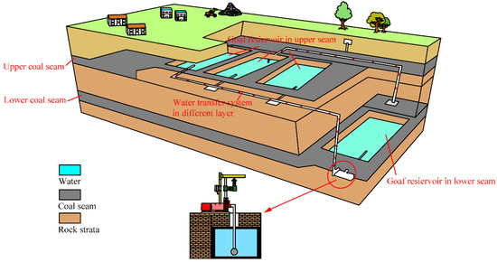
Figure 20.
Water transfer system in different layers.
6. Discussion
6.1. Comparisons with Existing Research
- Comparison with the key stratum theory
The key stratum was identified by comparing the bearing load of the adjacent rock layers, which is effective for analyzing fractures in the coal seam roof. However, when dealing with the interlayer strata in multi-seam systems, the development of fractures in the floor of the upper coal seam should also be taken into account. This theory is not well suited for analyzing fracture development in the floor.
- Comparison with the calculation method of the mechanical model
The mechanical model is often simplified into structural models, such as beams or plates, which is useful for qualitatively assessing whether the rock stratum fractures. However, the calculation of these mechanical models requires determining numerous parameters, many of which are typically assigned based on subjective judgment. The range of these parameter values directly influences the discrepancy between the calculated and measured results. In this research, an empirical formula was employed, which when combined with the measured data from a nearby mining area, offers a more practical approach.
- Comparison with the fuzzy mathematics theory
Many of the indices in fuzzy mathematics theory lack clear meaning and do not directly correspond to actual geological and mining factors. However, the theory does account for the influence of various factors, providing valuable insight for selecting linear formula parameters and for the classification of water inrush risk zones in this research.
6.2. Innovation and Universal Value of This Study
- An adaptive partitioning method of water inrush from overlying goaf
The study derived a multi-linear regression method for calculating the roof/floor fracture height/depth, and we propose a classification criterion for the water-inrush risk considering the relationship between the thickness of the WRB and the protective layer.
- Application value of the calculation formula
The empirical formula has been widely used in numerous engineering applications. When combined with measured data from the Lingzhida and other mines with similar geological conditions, it proves to be applicable to most geological settings. Moreover, the formula involves fewer parameters and is more closely aligned with the geological and mining conditions, making it easier for field engineers to apply.
- Application value of water-inrush risk zoning
After risk zoning of the mining area, a solid foundation is established for on-site production, allowing for the application of different mining methods in various zones. This approach not only prevents water-inrush accidents that could arise from mining the lower coal seam but also minimizes resource waste by avoiding the excessive retention of waterproof coal pillars, thereby improving the resource recovery rate.
In conclusion, each method for calculating the development of roof and floor fractures has its own advantages and limitations, requiring the selection of the appropriate method based on the specific research object. This research aimed to analyze the risk of roof water inrush during the mining of the lower coal seam across the entire Lingzhida Coal Mine, with the goal of optimizing the layout of future mining areas and working faces, as well as the related mining technologies. Therefore, by utilizing the empirical formula and fitting it to the existing measured data from the mining area and similar regions, the results can offer valuable guidance for field engineering practices.
7. Conclusions
This article focused on the safe mining of coal seams beneath accumulated water in goaf areas, and the main conclusions are as follows.
- According to the distribution of interlayer strata fractures after upper and lower coal seam mining, the multi-seam was divided into three categories: primary connectivity type, secondary connectivity type, and unconnected type. Based on the classical empirical formula, combined with the field measured data, the development height/depth calculation method of roof/floor strata was obtained by multiple linear regression fitting.
- The role of the WRB is proposed with consideration of the relationship between the thickness of the interlayer strata and the roof/floor fractures height/depth. Based on the relationship between the thickness of the WRB (Hw) and the protective layer (Hp), a classification criterion for water-inrush risk was established, dividing the mining area into four risk zones: high-risk (Hw < 0), medium-risk (0 ≤ Hw < 0.5Hp), low-risk (0.5Hp ≤ Hw < Hp), and safe (Hw ≥ Hp).
- Based on the distribution characteristics of water accumulation in the goaf of the 3# coal seam, zones for water-preserved coal mining were delineated, including pre-drained, water-preserved, and normal zones. Targeted water-preserved mining technologies are proposed, such as the staggered layout of internal/external lower seam faces, reduced mining heights, and the transfer of water storage from goaf reservoirs.
Author Contributions
Methodology, Z.L. and Z.C.; writing—original draft, H.J.; writing—review and editing, Y.N., L.F., and L.M. All authors have read and agreed to the published version of the manuscript.
Funding
This work was supported by the Xinjiang Uygur Autonomous Region Key R&D Program Projects (2023B03009-1) and Open Project of Key Laboratory of Xinjiang Coal Resources Green Mining, Ministry of Education (KLXGY-KB2401).
Data Availability Statement
Some or all data, models, or codes that support the findings of this study are available from the corresponding author upon reasonable request.
Conflicts of Interest
Author Hao Jiao was employed by the company Shanmei International Energy Group Co., Ltd. The remaining authors declare that the research was conducted in the absence of any commercial or financial relationships that could be construed as a potential conflict of interest.
Nomenclature
The following symbols are used in this paper:
| Hc | thickness of the interlayer strata between the upper and lower coal seams |
| Hf | depth of the floor fracture zone after the upper seam is mined |
| Hf-2 | secondarily developed depth of the floor fracture zone |
| Hf1, Hf2, and Hf3 | depth of the floor fracture according to different engineering conditions |
| Hr | height of the roof fracture zone after the lower seam is mined |
| Hm | buried depth of the coal seam |
| θ | dip angle of the coal seam |
| L | inclined length of the coal seam |
| M | mining height |
| a and b | coefficient related to the mine’s geological conditions |
| Hw | residual intact strata (WRB) after upper and lower seam mining |
| hloose | thickness of the loose layer above the coal seam |
| hclay | thickness of the clay layer at the bottom of the loose layer |
| A = ∑M/n, ∑M | total thickness of coal seams; n is the number of coal seams |
| Lnc | critical internal staggered layout distance |
| Lb | distance between the maximum depth point of the floor fracture and the coal wall |
| α | moving angle of WRB |
| Lwc | critical external staggered layout distance |
| La | distance between the maximum outside point of the floor fracture and the coal wall |
| β | full mining angle of WRB |
| Hd-cri | critical height of the roof fracture in the safe zone during lower coal seam mining |
References
- Chen, G.W.; Yang, T.H.; Liu, H.Y.; Wei, L.; Zhao, Y.; Liu, Y.L.; Qian, J.W. Characteristics of stratum movement induced by downward longwall mining activities in middle-distance multi-seam. Int. J. Rock. Mech. Min. 2020, 136, 104517. [Google Scholar] [CrossRef]
- Ghabraie, B.; Gang, R.; Barbato, J.; Smith, J.V. A predictive methodology for multi-seam mining induced subsidence. Int. J. Rock. Mech. Min. 2017, 93, 280–294. [Google Scholar] [CrossRef]
- Morrison, K.G.; Reynolds, J.K.; Wright, I.A. Subsidence fracturing of stream channel from longwall coal mining causing upwelling saline groundwater and metal-enriched contamination of surface waterway. Water Air Soil Pollut. 2019, 230, 37. [Google Scholar] [CrossRef]
- Sun, W.J.; Li, W.J.; Wu, Q.; Zhao, S.Q.; Liu, W.; Wang, C.X. Unraveling the spatio-temporal pattern of mine water accidents in China. Mine Water Environ. 2025, in press. [CrossRef]
- Case of the “11.29” Major Water Leakage Accident at Yuanjiangshan Coal Mine of Leiyang Daozi Coal Industry Co., Ltd. in Hengyang City, Hunan Province. Available online: https://www.chinamine-safety.gov.cn/zfxxgk/fdzdgknr/sgcc/sgalks/202107/t20210728_393109.shtml (accessed on 28 July 2021).
- Case of the “4.10” Major Water Inrush Accident at Fengyuan Coal Mine in Baiyanggou, Hutubi County, Changji Prefecture, Xinjiang. Available online: https://www.chinamine-safety.gov.cn/zfxxgk/fdzdgknr/sgcc/sgalks/202201/t20220119_406923.shtml (accessed on 19 January 2022).
- Case of the “6.1” Major Water Damage Accident at Shandong Energy Xinwen Mining Group Co., Ltd. Huafeng Coal Mine. Available online: http://nmg.chinamine-safety.gov.cn/Item/13389.aspx (accessed on 16 January 2025).
- Galvin, J.M. Ground Engineering-Principles and Practices for Underground Coal Mining; Springer: Berlin/Heidelberg, Germany, 2016. [Google Scholar]
- Palchik, V. Experimental investigation of apertures of mining-induced horizontal fractures. Int. J. Rock. Mech. Min. 2010, 47, 502–508. [Google Scholar] [CrossRef]
- Duan, K.J.; Gong, P.L.; Yi, K.; Wen, G.; Kang, H.; Feng, Z.Y.; Zhao, T.; Li, P. Failure law of soft and hard interlayer overlying rock in gently inclined, super-thick coal seam and research on the development height of a water-conducting fissure Zone. Energy Sci. Eng. 2025, 1–18. [Google Scholar] [CrossRef]
- Ti, Z.Y.; Li, J.Z.; Wang, M.; Li, X.Y.; Jin, Z.P.; Tai, C.W.; Wang, K. Fracture characteristics and zoning model of overburden during longwall mining. Shock Vib. 2021, 2021, 2857750. [Google Scholar] [CrossRef]
- Hou, P.F.; Wang, S.M.; Feng, D.; Xie, X.S.; Hou, E.K. Surface movement and crack development laws of super-long working faces in medium-depth coal seam mining. Front. Earth Sci. 2024, 12, 1526950. [Google Scholar] [CrossRef]
- Fan, L.M.; Ma, X.D. A review on investigation of water-preserved coal mining in western China. Int. J. Coal Sci. Technol. 2018, 5, 411–416. [Google Scholar] [CrossRef]
- Miao, X.X.; Pu, H.; Bai, H.B. Principle of water-resisting key strata and its application in water-preserved mining. Int. J. Min. Sci. Technol. 2008, 37, 1–4. (In Chinese) [Google Scholar]
- Pu, H.; Yi, Q.Y.; Jivkov, A.P.; Bian, Z.F.; Chen, W.Q.; Wu, J.Y. Effect of dry-wet cycles on dynamic properties and microstructures of sandstone: Experiments and modelling. Int. J. Min. Sci. Technol. 2024, 34, 655–679. [Google Scholar] [CrossRef]
- Liu, S.L.; Li, W.P. Fuzzy comprehensive risk evaluation of roof water inrush based on catastrophe theory in the Jurassic coalfield of northwest China. J. Intell. Fuzzy Syst. 2019, 37, 2101–2111. [Google Scholar] [CrossRef]
- Wu, F.Z.; Du, J.M.; Sun, F.X.; Chen, G.; Jiang, F.J.; Zhu, Z.J. Multi-method coal seam floor water inrush risk evaluation based on variable weight theory. Energy Explor. Exploit. 2025, 43, 724–743. [Google Scholar] [CrossRef]
- Li, Z.H.; Xu, Y.; Li, L.F.; Zhai, C.Z. Forecast of the height of water flowing fractured zone based on BP neural networks. J. Min. Safety Eng. 2015, 32, 905–910. [Google Scholar]
- Zheng, X.Z.; Li, Y.; Tong, X.; Liu, Q.Y. Precise quantitative evaluation of the risk level of coal mine water inrush accidents based on the CW-BN model. Earth Sci. Inf. 2025, 18, 315. [Google Scholar] [CrossRef]
- Xu, Z.M.; Sun, Y.J. Mine Water Safety and Environment: Chinese Experience. Water 2024, 16, 2833. [Google Scholar] [CrossRef]
- Wu, Q.; Huang, X.L.; Dong, D.L.; Yin, Z.R.; Li, J.M.; Hong, Y.Q.; Zhang, H.J. “Three figure-two prediction method” for evaluating water inrush conditions of coal seam roof. J. China Coal Saf. 2000, 25, 62–67. [Google Scholar]
- Jin, Z.Y.; Peng, T. Control of the internal and external staggered distance of coal mining face to the water-conducting fissures in the overlying strata of the near coal. Adv. Civ. Eng. 2021, 2021, 1499675. [Google Scholar] [CrossRef]
- Guo, J.S.; Ma, L.Q. Permeability Distribution Characteristics and Water Resistance Evaluation of Interlayer Rock Strata During Multi-seam Coal Mining. Mine Water Environ. 2025; in press. [Google Scholar]
- Li, Q.Z.; Fan, G.W.; Zhang, D.S.; Yu, W.; Zhang, S.Z.; Fan, Z.L.; Fu, Y. Novel method on mixing degree quantification of mine water sources: A case study. Processes 2024, 12, 438. [Google Scholar] [CrossRef]
- Dai, J.L.; Wei, Z.X.; Pan, Z.Y.; Yin, R.C.; Wu, Y.B.; Guan, Z.D. Research on environmental geological problems caused by water and mud inrush in tunnels and long-term drainage: Taking chaoyang tunnel of guinan high-speed railway as an example. Carbonate Evaporite 2024, 39, 115. [Google Scholar] [CrossRef]
- Dai, X.L.; Gao, R.; Du, F.; Yu, B.; Meng, X.B.; Tai, Y. Evolution and control of overburden fracture in extra-thick coal seam mining with hard roofs: Ground grouting sealing and case study. Bull. Eng. Geol. Environ. 2024, 83, 262. [Google Scholar] [CrossRef]
- Zhang, D.S.; Fan, G.W.; Liu, Y.D.; Ma, L.Q. Field trials of aquifer protection in longwall mining of shallow coal seams in China. Int. J. Rock. Mech. Min. 2010, 47, 908–914. [Google Scholar] [CrossRef]
- Shi, L.Q.; Qi, Y.S.; Xu, D.J.; He, Z.Y.; Zhang, J.W. Leaching behaviour of arsenic in coal under the action of mine water. J. Geol. Soc. 2025, 182, 86. [Google Scholar] [CrossRef]
- Majdi, A.; Hassani, F.P.; Nasiri, M.Y. Prediction of the height of destressed zone above the mined panel roof in longwall coal mining. Int. J. Coal Geol. 2012, 98, 62–72. [Google Scholar] [CrossRef]
- Moon, J.; Jeong, S. Effect of highly pervious geological features on ground-water flow into a tunnel. Eng. Geol. 2011, 117, 207–216. [Google Scholar] [CrossRef]
- Howladar, M.F. Coal mining impacts on water environs around the Barapukuria coal mining area, Dinajpur, Bangladesh. Environ. Earth Sci. 2013, 70, 215–226. [Google Scholar] [CrossRef]
- Ma, L.Q.; Ghorbani, Y.; Kongar-Syuryun, C.B.; Khayrutdinov, M.M.; Klyuev, R.V.; Petenko, A.; Brigida, V. Dynamics of backfill compressive strength obtained from enrichment tails for the circular waste management. Resour. Conserv. Recycl. Adv. 2024, 23, 200224. [Google Scholar] [CrossRef]
- Xu, J.L.; Ju, J.F. Structural morphology of key stratum and its influence on strata behaviors in fully-mechanized face with super-large mining height. Chin. Lournal Rock Mech. Eng. 2011, 30, 1547–1556. [Google Scholar]
- Sui, W.H.; Hang, Y.; Ma, L.X.; Wu, Z.Y.; Zhou, Y.J.; Long, G.Q.; Wei, L.B. Interactions of overburden failure zones due to multiple-seam mining using longwall caving. Bull. Eng. Geol. Environ. 2015, 74, 1019–1035. [Google Scholar] [CrossRef]
- Lyu, X.; Yang, K.; Xu, C.S.; Fang, J.J.; Duan, M.K.; Zhang, Z.N. Experimental study of mechanical properties of artificial dam for coal mine underground reservoir under cyclic loading and unloading. Geomech. Geophys. Geo-Energy Geo-Resour. 2024, 10, 91. [Google Scholar] [CrossRef]
Disclaimer/Publisher’s Note: The statements, opinions and data contained in all publications are solely those of the individual author(s) and contributor(s) and not of MDPI and/or the editor(s). MDPI and/or the editor(s) disclaim responsibility for any injury to people or property resulting from any ideas, methods, instructions or products referred to in the content. |
© 2025 by the authors. Licensee MDPI, Basel, Switzerland. This article is an open access article distributed under the terms and conditions of the Creative Commons Attribution (CC BY) license (https://creativecommons.org/licenses/by/4.0/).