Article

Assessment of Sediments’ Transport Triggering Processes through the Identification of Deposition Shapes in Large Reservoirs

1
IGA Research Group, High Polytechnic School of Avila, University of Salamanca, Av. de los Hornos Caleros, 50, 05003 Ávila, Spain
2
Forest, Water & Soil Research Group, Catholic University of Ávila, C/Canteros s/n, 05005 Ávila, Spain
3
Department of Geology, High Polytechnic School of Zamora, University of Salamanca, Av. de Requejo, 33, 49022 Zamora, Spain
4
IGA Research Group, Department of Statistics, University of Salamanca, Campus Miguel de Unamuno, C/Alfonso X El Sabio s/n, 37007 Salamanca, Spain
5
Department of Animal Biology and Ecology, Faculty of Biology, University of Salamanca, Campus Miguel de Unamuno, C/Donantes de Sangre s/n, 37007 Salamanca, Spain
*
Author to whom correspondence should be addressed.
Water 2024, 16(7), 960; https://doi.org/10.3390/w16070960
Submission received: 28 February 2024 / Revised: 18 March 2024 / Accepted: 22 March 2024 / Published: 26 March 2024

Abstract

:
Sediment deposition at the bottom of artificial reservoirs has become a worldwide problem. This comprises a dual issue that is, in the first place, associated with the reduction in storage capacity and lifetime of large reservoirs. The second aspect comprises the threat that the sediment represents for the dam structure. This research is mainly aimed at identifying and inferring the main sediments’ triggering processes through a rigorous analysis of deposition shapes in a large reservoir. For identifying the main deposition shapes, a sequential methodology was designed and developed comprising the following stages. First, an analysis of XYZ cartography from bathymetric development was conducted. Then, a shapes categorization was developed that comprises the identification of six types of shapes based on four parameters: slope continuity, slope break, absolute and relative slope, and arc configuration. The third stage comprised a visualization and spatial calculation of shapes through GIS-based cartography. The fourth stage comprised an interpretation of deposition shapes processes: for that, a dual analysis was developed. First, an analysis based on fluvial sediments transport processes was realized. The second stage implied an analysis of the dam influence on fluvial hydrodynamics and sediments transport. Results comprised a quantitative assessment of each shape as well as physical processes identification and interpretation, generating a robust equivalence between shapes and triggering processes. This research proved successful for the identification and characterization of the main deposition and transport processes that may help to prevent, palliate, and/or correct phenomenon of silting in large reservoirs. This detailed knowledge of deposition forms opens new strategies to release sediments from storage water more effectively.

1. Introduction

Sediment deposition at the bottom of artificial reservoirs has become a worldwide problem [1] that represent a dual problem. First, it is related to the reduction in storage capacity and lifetime. In this sense, associated impacts may comprise a capability reduction to provide water for irrigation, hydropower production, and other uses, as well as to intercept floods and regulate the flow. Second, problems come from the threat that the sediment represents for the dam structure. If the sediment deposits are too close to the structure, they may block the outlets affecting the dam safety. Also, if highly charged water passes through the turbines, it causes abrasion of mechanical equipment. This may decrease power generating efficiency and ultimately result in a loss of production time during its repair [2].
This process produces enormous impacts on different dimensions of water services delivered by reservoirs. Some of them are water supply, electricity generation, food production, and reservoir maintenance costs [3]. On the other hand, this also produces environmental consequences through degradation of water quality and loss of biodiversity [4]. Furthermore, this also produces inefficiencies in reservoirs functioning that can challenge the hydraulic engineering design. Finally, this may induce very serious associated risks that are less common but can be very dangerous, such as overflowing of reservoirs due to flood waves, or massive bank slides [5,6].
Annual global water storage loss caused by sedimentation is placed around 1% [2,7,8]. It is forecasted that by the end of this century, the world’s water storage capacity will decline by over 50% [9]. This primarily stems from the absence of a holistic and integrated strategy for creating a durable and sustainable strategy for managing sedimentation in dams and reservoirs [10]. In this sense, a whole plan should incorporate a sequential nature that incorporates three chronological phases: preventive, mitigative, and corrective measurements. It is clear to see the lack of preventive actions that have been taken during the initial decades of dam/reservoirs’ functioning.
From a corrective point of view, existing dams and other storing structures continuously trap sediment and have no specific specifications for sustained long-term use. The whole duration of their storage capacity was frequently designed to be less than 100 years [11], and, in practice, usually achieved much shorter. A famous case of a dam structure reconstructed to deal with the sedimentation problem is the Sanmenxia Dam on the Yellow River in China [12]. The reconstruction was based on a restoration of sediment balance through an improvement and optimization of sediment-discharging capacity at the outlet. Furthermore, other successful strategies developed are briefly described as follows: the flushing process [13] was developed for the removal of existing deposited sediment. For instance, a study conducted Doretto et al. [14] focused on addressing the removal of deposited sediment, with particular attention paid to the environmental challenges associated with dams.
Reservoir operation in problematic dam/reservoirs systems is greatly affected by sediment dynamics [15]. Extreme rainfall–runoff events are the ones that produce more sediments’ transportation, and the question is whether to keep the reservoir water high or low on those occasions. High waters at extreme events may produce a major sediment deposition, while low waters can produce more bed erosion and consequent remobilization. Sediment dynamics knowledge comprises the understanding of transport–deposition driving forces and, consequently, that is the reason why the study of deposition shapes becomes a crucial issue.
Preventive interventions are largely based on sediment management to be developed at catchment scale, normally on headwaters. Those interventions may be based on the reduction in sediment inflow either by soil erosion control, upstream sediment trapping, or sediment bypass [16].
Various methods to determine sedimentation management and, indirectly, deposition shapes have been developed and used depending on conditions such as data accessibility, measurement purpose, or budget. The application of numerical models that can simulate the extended accumulation of sediment in reservoirs is widespread. To achieve this, one-dimensional, such as RESSASS, Mike 11, HEC-6, FLUVIAL, SRH-1D, and the Hydrologic Engineering Center’s River Analysis System (HEC-RAS 1D), and two-dimensional models (IBER+, SSIIM, WOLF-2D, SRH-2D, MIKE21, BASEMENT) are frequently employed [17,18,19]. Finally, 3D CFD (computational fluids dynamics) are also currently being employed worldwide [20]. The choice between them is largely based on geometrical issues (length–width relation, etc.) and computational needs. On the other hand, digital bathymetric measurement is one of the most common and accurate methods used to evaluate sedimentation shapes.
In the search for reservoir sedimentation studies, current trends show two noticeable patterns: an increase in sedimentation rates in many reservoirs in recent decades, primarily due to heightened soil erosion stemming from land use changes, and more intense rainfall events [4,21,22,23].
Urban growth, reduced vegetation cover, and intensified agriculture contribute to increased soil erosion rates [21,24,25]. Studies have linked human expansion to annual soil loss in catchment areas [25]. Reservoir sediment accumulation is associated with demographic growth, reaching high correlation coefficients [26,27,28]. Seasonal rainfall variation due to global temperature rise is a secondary influence on soil erosion and sediment deposition [21,29,30]. On the contrary, some studies show declining sedimentation rates in certain reservoirs due to human interventions and climatic factors [31,32,33]. Conservation practices, like improved land management and afforestation, contribute to lower soil erosion and sediment yield. Changes in reservoir management strategies, such as sediment retention structures and spillway reconstruction, are effective in addressing sediment deposition [30,33]. In some regions, fewer flooding events and decreased inflows due to climate change have also led to reduced sedimentation rates [34,35,36].
In the review of sedimentation rates conducted by González-Rodríguez et al. [9], it was concluded that the accumulation of sediments in water reservoirs has significant consequences for their storage capacity, longevity, and the quality of the contained water. As a result, changes in precipitation patterns and land use will lead to alterations in the erosion rate, directly affecting sedimentation rates. In this sense, oil and sediment management approaches implemented upstream of certain impounded reservoirs have proven to be efficient in mitigating and addressing reservoir sedimentation.
This research is mainly aimed at identifying the main transport and deposition triggering processes through a rigorous analysis of deposition shapes in large reservoirs. As a secondary goal, this will allow further understanding of these processes for preventing, palliating, and/or correcting the reservoirs’ silting phenomenon.

2. Materials and Methods
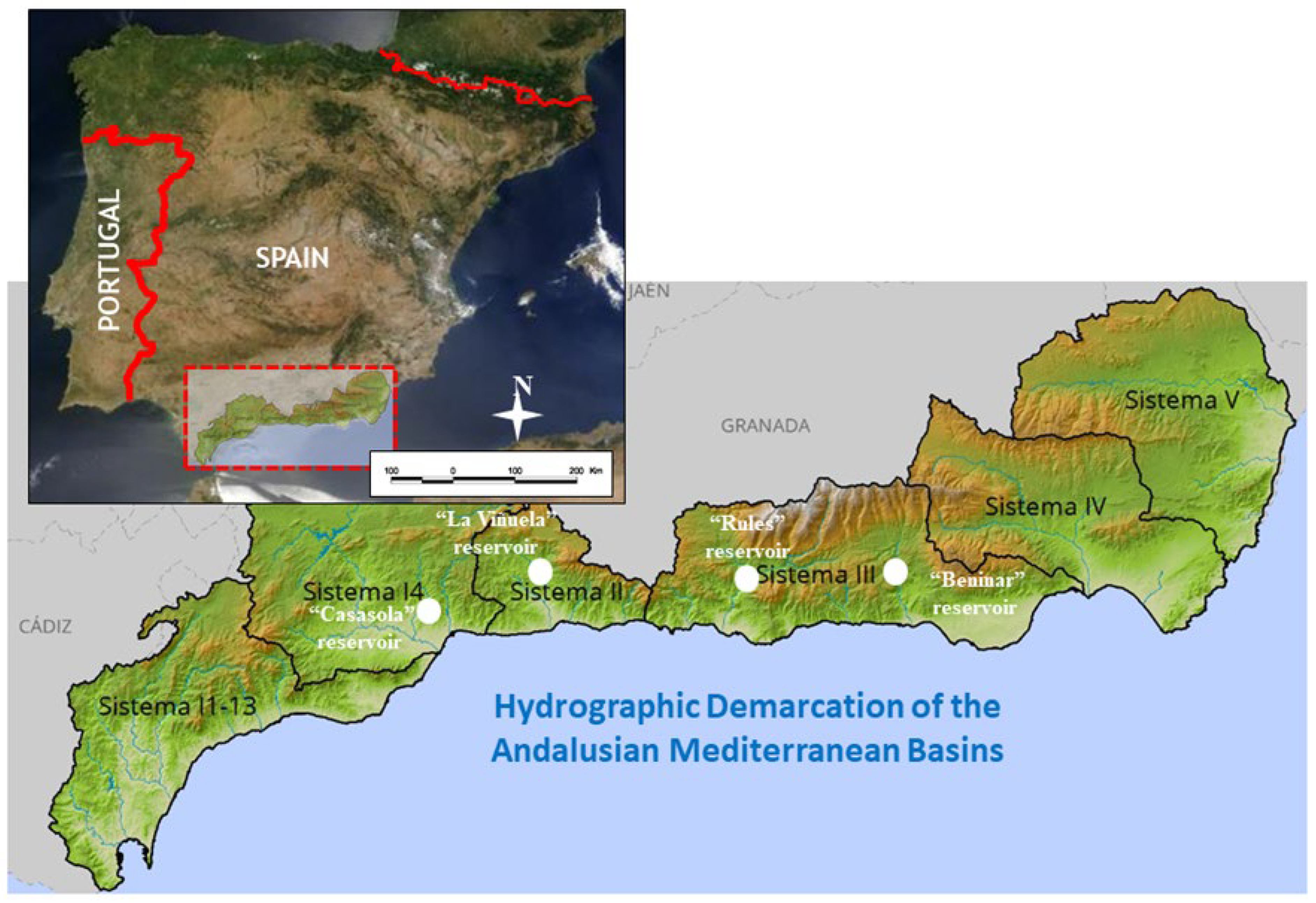
2.1. Study Area

This case study has several peculiarities that makes it very interesting for analyzing the triggering processes of sediment transport through the assessment of depositional shapes on the reservoir basin. The climate is Mediterranean, with an average annual rainfall of 665 mm and an average annual temperature of 14.3 °C. The soil erodibility factor (K) and the rain erosivity factor (R) [37] are estimated at 0.0576 pc and 124 pc, respectively. The Bouyoucos [38] erodibility index is estimated at 10.88.
The Rules reservoir receives inflows from the Guadalfeo River, whose mouth is 19.5 km downstream of the dam. The Rules reservoir collects water from the Guadalfeo River whose tributaries on the left bank are the Lanjarón, Chico, Poqueira, Trevélez, and Cádiar rivers and the Ízbor on the right. The downstream boundary is located 2.5 km downstream from the confluence of the Ízbor River with the Guadalfeo River, in the municipality of Vélez de Benaudalla, province of Granada. It should also be noted that the catchment basin of the reservoir under study includes the Beznar dam, located upstream of the Rules dam.
The Rules reservoir and its catchment basin are located in the intricate geological area of the Bétic Ranges. The reservoir is formed by three main branches; the first is formed by the Ízbor River, which runs in a northwesterly direction. The second is formed by the Guadafeo River, extending in a southeasterly direction. Finally, there is the branch where the dam is located, formed by the Guadalfeo River once the Ízbor River joins it.
The average annual rainfall of the whole system is about 665 mm. The average annual contribution is 150 hm3 from the Guadalfeo River to the Rules reservoir with a surface area of 1070 km2. From the Ízbor River, the surface area of its catchment basin covers 352 km2, with an average annual contribution of 56.5 hm3. The geology and geotechnics of the downstream boundary are formed by a Paleozoic rocky substratum and postorogenic formations.
The Rules dam is classified as Category A according to its potential risk, in accordance with the provisions of the Basic Civil Protection Planning Guideline for Flood Risk. Officially, the dam was inaugurated on 20 May 2004, and the first step of filling occurred on 4 June 2007, taking advantage of the contributions that took place, and this caused the level of the reservoir to rise, storing 15.5 hm3.
The purpose of the Rules reservoir is to regulate the natural water resources of the Guadalfeo basin within a system formed by the reservoirs of Rules and Beznar, located on the Ízbor river, being exploited jointly. The main uses of the Rules reservoir can be classified as follows: Interannual regulation of the contributions of the Guadalfeo River basin in conjunction with the Beznar dam; satisfaction of the supply, urban, industrial, and irrigation demands, old, new, and future, as well as satisfaction of the ecological demand; flooding control in the Guadalfeo River basin; electricity production by means of the hydroelectric power plant at the foot of the dam and its corresponding power evacuation lines; possible recreational uses.
The Rules dam is made of concrete with a gravity profile and a curved plan. The cross-section of the dam is trapezoidal, with a slope of 0.18 H:V on the upstream face and 0.6 H:V on the downstream face, with a curved plan of 500 m radius. The crest of the dam is at 248.2 m a.s.l.; it has a length of 610.434 m and a total width of 10 m. The minimum foundation elevation is 118.2 m a.s.l., at which point the riverbed flows at 160.3 m a.s.l. The total heights above bed and foundation are 130 m and 87.9 m, respectively. The reservoir volume at NMN is 110.81 hm3.
The body of the dam is crossed by five horizontal galleries, at elevations of 130.30–150.30–175.30–200.30 and 225.30, with longitudinal and transversal directions, allowing inspection, monitoring, and control of the auscultation devices.
The spillway has a fixed lip and is centered on the body of the dam. It has seven spans of 16.53 m of free span and the spillway length is 115.68 m. The cross-section corresponds to that of a Creager profile with a spill at 243.3 m a.s.l. In addition, to dissipate the energy of the spill, there is a stilling basin with an overtopping submerged in the riverbed.
The Rules dam has an intermediate spillway composed of two conduits at elevation 193.79 and two bottom spillway conduits located at elevation 171.575 m a.s.l. In addition, there are three supply intakes at different elevations and an irrigation intake.
The Guadalfeo River has a length of 69.6 km and its most important contribution comes from the Sierra Nevada, with the first 15 km of its course running north–south. Then, until the P.K 50, it has a west–southwest direction. Once the Ízbor River flows into it, it crosses the Sierras de Lújar and Los Guajares to flow into the Vega de Motril Salobreña.
The Rules dam receives the contributions of the Guadalfeo River, whose mouth is 19.5 km downstream of the dam. The Rules reservoir collects water from the Guadalfeo River; its tributaries on the left bank are the Lanjarón, Chico, Poqueira, Trevélez, and Cádiar rivers and the Ízbor on the right. The downstream boundary is located 2.5 km downstream of the confluence of the Ízbor River, with the Guadalfeo River in the municipality of Vélez de Benaudalla, province of Granada. It should also be noted that the catchment basin of the reservoir under study includes the Beznar dam, located upstream of the Rules dam. The Rules reservoir and its catchment basin are in the intricate geological area of the Betic Mountains. The reservoir is formed by three main branches: the first is formed by the Ízbor River, which runs in a northwesterly direction. The second is formed by the Guadafeo River, extending in a southeasterly direction. Finally, the arm where the dam is located is formed by the Guadalfeo River once the Ízbor River joins it. The Rules dam is located on Sheet 1042 (scale 1:50,000) of the National Geographic Institute, and the UTM coordinates, Zone 30N, are 455,960, 4,079,610.
A preliminary analysis of the results offered by the National Soil Erosion Inventory (“Inventario Nacional de Erosión de Suelos”) shows the selected basins’ response [39]. The main erosion indicators, which are laminar in rivers and potential for mass movements, are among the highest of the inventory, although their values are uneven. They all show high soil losses, which justify the notable capacity loss in the exploitation of the Rules reservoir of 25%.
Concerning the mass movements or landslides surrounding reservoirs, they are recognized as events that can activate sediment transport from subaerial to underwater environments, especially in mountainous regions [40]. Sometimes these processes take place in a continuous manner, involving millimetric annual movements [41], and the sediment contribution is related to the river erosion at the toe of the mobilized mass. It is also common that these events experiment an acceleration, caused not only by the river erosion but also by the reduction in the strength properties of the mobilized mass. Finally, there are cases in which the equilibrium condition is lost instantaneously—sometimes with catastrophic consequences—and depending on the mass dimensions and reservoir characteristics, this can give rise to the generation of impulse waves [20,42]. These types of events are difficult to prevent, and some attempts have been made to forecast them [43].
A selected case study has been agreed upon with the governmental entity in charge of their management, which is the General Direction of Water Infrastructures (GDWI)-Junta de Andalucía (Figure 1).

2.2. Methods

There are several methods available for studying the behavior of sediments’ transport process and, consequently, to address the phenomenon of reservoir silting and its management. The most important are described as follows.
  • Mathematical modeling: 1D and 2D numerical model simulations can be employed to forecast the long-term sediment deposition patterns in reservoirs. The long-term sediment deposition of a reservoir can be estimated using the one- or two-dimensional numerical modeling approach. Both approaches can be developed through RESSASS (1D) and IBER software, respectively (2D) [45,46].
Furthermore, 3D computational fluid dynamics (CFD), such as Ansys Fluent, has been extensively validated in a wide variety of applications. In addition, one can create advanced physical models and analyze a variety of fluid-related phenomena, all in a customizable and intuitive environment. RESSASS (Reservoir Survey Analysis and Sedimentation Simulation) is a Windows-based software program developed by HR Wallingford in 2001 [46]. This one-dimensional steady-state model is specifically designed to simulate sediment dynamics within river and reservoir systems. RESSASS conducts simulations of water flow and sediment transport for each time increment and section along a river [2]. It provides valuable forecasts regarding long-term deposition patterns in reservoirs, the depletion of storage capacity, sediment concentrations, bed composition, and more in cross-sectional profiles. It comprises three key submodels: Volume Analysis, Volume Prediction, and Numerical Model. The model’s calculations involve two primary steps: backwater computations and sediment transport computations. In the initial step of the calculations, backwater calculations are performed to calculate the depth and velocity of flow and water depths at each cross-section along the river reach. In the subsequent step, computed flow velocities and depths from the backwater calculations are utilized to determine potential sediment transport rates by employing a sediment transport formula. The model categorizes sediments into two distinct size ranges: fine sediments (silt and clay, smaller than 0.06 mm) and coarse sediments (sand and gravel, larger than 0.06 mm), each of which can be further subdivided into multiple fractions. The method of Westrich and Jurashek [47] is used for determining maximum concentration before deposition is adopted in calculations of transport rates of fine sediment. To calculate the carrying capacities of coarse sediments, the model employs a revised version of the Ackers and White [48] method. The density of settled sediment plays a pivotal role in converting the mass of deposited or eroded sediment into volume changes. The model takes into account two critical factors when determining representative sediment density, as outlined by Ali and Sterk [49]: the initial density, which is dependent on the relative proportions of sand, silt, and clay, and the consolidation of settled material, resulting in an increase in density over time. To estimate initial densities, the Lara and Pemberton [50] Equation (1) is applied:
D 0 = D c · R c + D s · R s + D s a · R s a
where D0 is the initial density; Dc, Ds, and Dsa are the initial densities for clay, silt, and sand, respectively; and Rc, Rs, and Rsa are the ratios of clay, silt, and sand, respectively.
Iber [45] is a numerical model designed for solving the depth-averaged shallow water equations in a two-dimensional (2D) framework using an unstructured explicit finite volume solver. Beyond its core hydraulic module, it also incorporates sediment transport and water quality components [51] to address the movement of materials in open-surface shallow flows. To simulate flood inundation, Iber employs the first- and second-order extensions of the upwind scheme developed by Roe [52], while for managing rainfall–runoff scenarios, it employs the DHD (decoupled hydrological discretization) scheme [51] to handle the shallow water equations.
h t + h U x x + h U y y = r i
h U x t + x h U x 2 + g h 2 2 + y h U x U y = g h Z b x τ b , x ρ + x υ t h U x x + y υ t h U x y
h U y t + y h U y 2 + g h 2 2 + x h U x U y = g h Z b y τ b , y ρ + x υ t h U y x + y υ t h U y y
Furthermore, the equations that explain the sediment transport processes and that objectify the balance of inflows in the reservoir adopt the premise that the solid flow is the product of a mixture of diameters, the entrainment of which occurs in a thickness of the river bottom known as the active layer [53]. This conceptualization leads to the consideration of the total solid flow at each point qb as a sum of this flow for each considered diameter qks [54]:
q b = k = 1 n q k s
The value of qks represents the transport capacity evaluated with a solid transport formula. The continuity of the solid flow at the bottom of the channel is reflected in Exner’s equation:
1 p z b t + k s = 1 n º   c l a s e s q k s , x x + q k s , y y = 0
This allows us to address the total mass balance for each diameter ks by means of the following:
F k s = 1 p ( β k s h a ) t + q k s , x x + q k s , y y
where p is the porosity, βks is the fraction of the diameter ks in the active layer, ha is the thickness of the active layer, and Fks is the source of sediments of that class to the active layer.
Since this research is based on ground truth measurements, results may be useful for modeling (1D, 2D, 3D) validation and calibration.
2.
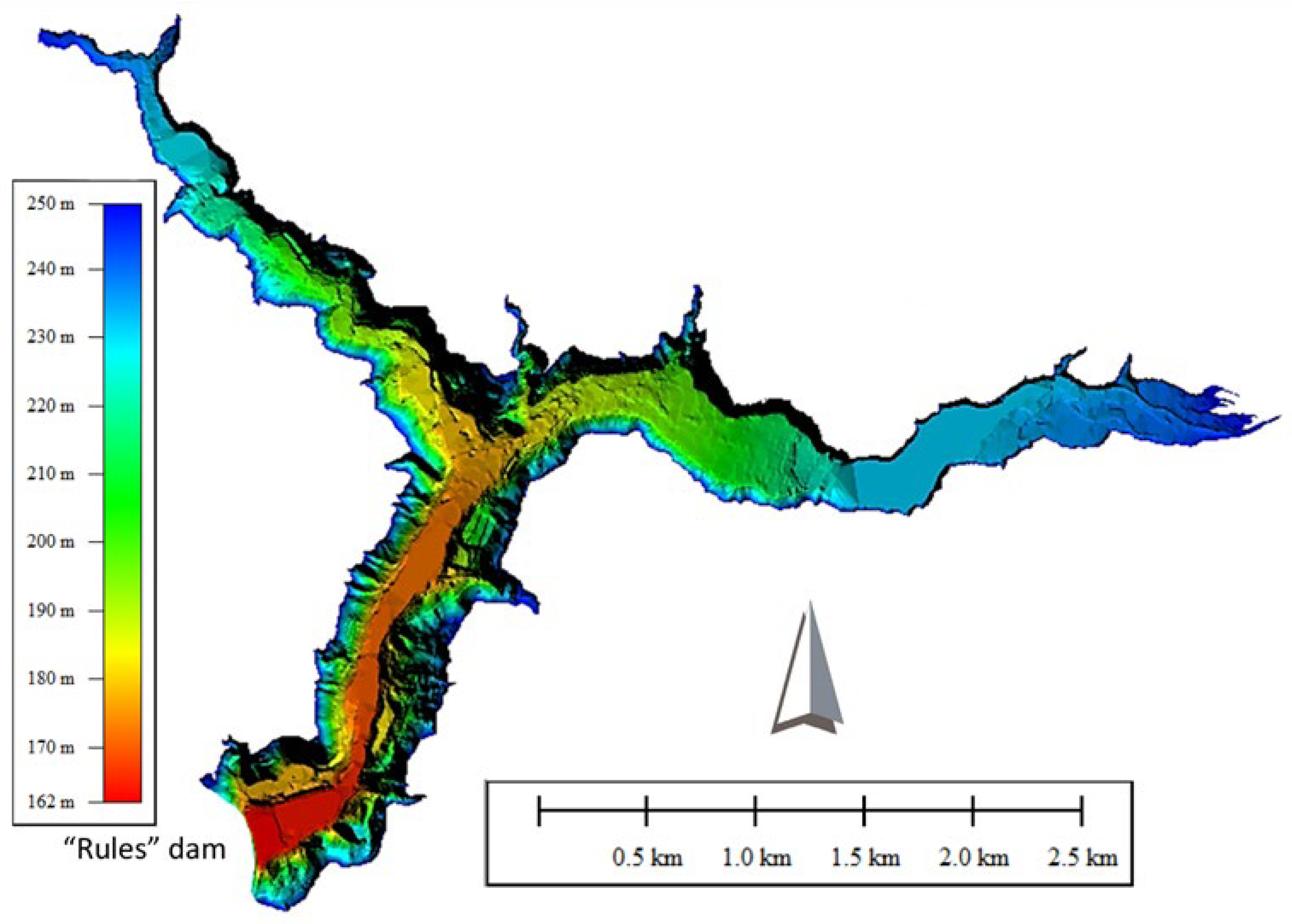
Bathymetric and topographic approach: This was the selected method for this research. This method uses acoustic signals and geolocation technologies to reproduce the underwater topography [31,55]. In this research, the equipment used was an Applanix SurfMaster GNSS/INS GPS integrated system with two GPS TRIMBLE antennas. This mobile equipment provides coordinates to the Hypack2021 navigation system for the correct positioning of the data acquired by the multibeam system. Bathymetry was carried out with a multibeam system (NORBIT iWBMSe), planning parallel lines as far as possible, overlapping by 20%, to ensure 100% coverage of the surveyed area. Data acquisition was carried out at 400 kHz, with a sampling frequency of 512 beams every 10–20 Hz. Bathymetric data acquisition was carried out on 5 June 2023. The acquisition and recording system were a computer equipped with digital data acquisition with georeferencing of the information. The software used for data collection and processing was the Hypack-Hysweep software. During the bathymetric survey, 96 lines totaling 45 km were traversed (Figure 2).
3.
Core chronology: This is a traditional technique used to measure sediment deposition with high temporal resolution over periods of up to 100–150 years [20,30,56]. This method involves a huge spectrum of techniques developed in the field for data sediments. This is crucial for estimating the impact of climate change with a sufficient temporal perspective.
4.
Hydrological calculation: Hydrological data are used in mathematical formulae to calculate sedimentation and trap efficiency. Here, equations and models are selected according to the type, quality, and frequency of the data available [11,57]. For this method, the detailed characterization of normal and extreme hydrological events is crucial. Furthermore, there is an emerging research line in predictive hydrology based on the dependence study of hydrological events [4,20,21,22].
5.
Satellite imaging and remote sensing techniques have been proposed as alternative methods to monitor sedimentation [31,58]. The support of services on Earth observation equipment like Copernicus (component of the European Union’s Space programme) is crucial for capturing the dynamics and real-time temporal evolution of the sediment silting phenomenon.

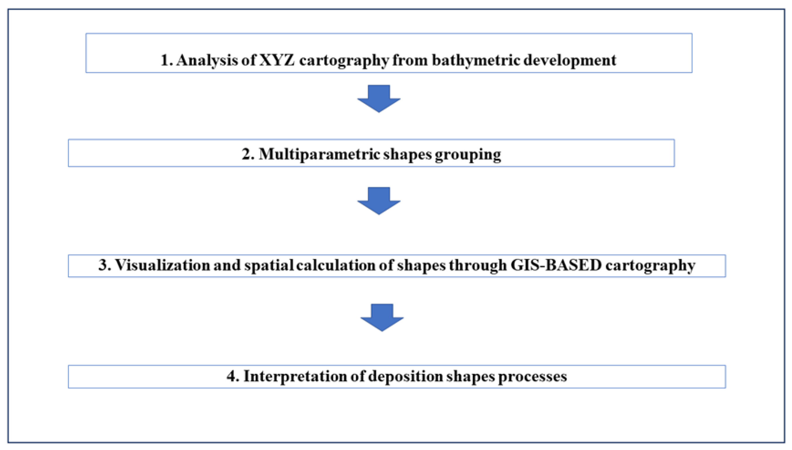
2.3. Research Concept

Identification of key deposition shapes was achieved through the following methodology (Figure 3).
First, an analysis of XYZ cartography from bathymetric development was conducted. Then, a multiparametric shapes grouping was performed according to certain criteria to be explained later. Finally, a visualization and spatiotemporal calculation were performed through GIS-based cartography. In more detail:
  • Analysis of XYZ cartography from bathymetric development (Figure 4). The first step comprised a detailed analysis of the reconstruction of a bathymetric and topographic model obtained from the aforementioned method. This analysis comprised different aspects such as the location of vertical jumps, flat areas, breaking lines, slope at different areas and general slope, identification of dynamic sediment curves, and geometry of the sediment breakthrough front, among others.
  • Multiparametric shapes identification. Based on the pervious analysis, six categories of shapes were identified based on four parameters, listed as follows: slope continuity, slope break, absolute and relative slope, and arc configuration. The established thresholds and ranges for the slope are described as follows: 0 (Flat); 0–1.16 (SubFlat); 1.16–2.5 (Non-Vertical Jump); >2.5 (Vertical Jump). Furthermore, BLs were established for each change of shape.
In this sense, categories were the following: Flat Areas (Fas), SubFlat Areas (SFAs), Breaking Lines (BLs), Vertical Jumps (VJs), Non-Vertical Jumps (NVJs), and Arc-Lines (ALs). Non-Vertical Jumps are currently being studied by developing mathematical modeling of those curves. This gives a powerful tool for describing and predicting the future behavior of those fronts that may be an important source of risk.
3.
Visualization and spatial calculation of shapes through GIS-based cartography. Mapping digitalization was conducted to spatially characterize the different shapes of sediments deposition (please see Figure 6).
4.
Interpretation of deposition shapes processes. For this, a double-stage analysis was developed. First, an analysis based on transport processes was realized for reaching the second phase (multiparametric shapes identification). This comprised an analysis of deposition processes that lead to the previously identified shapes. The second stage complemented the previous study by developing an analysis of the dam influence on fluvial hydrodynamics and sediments transport.

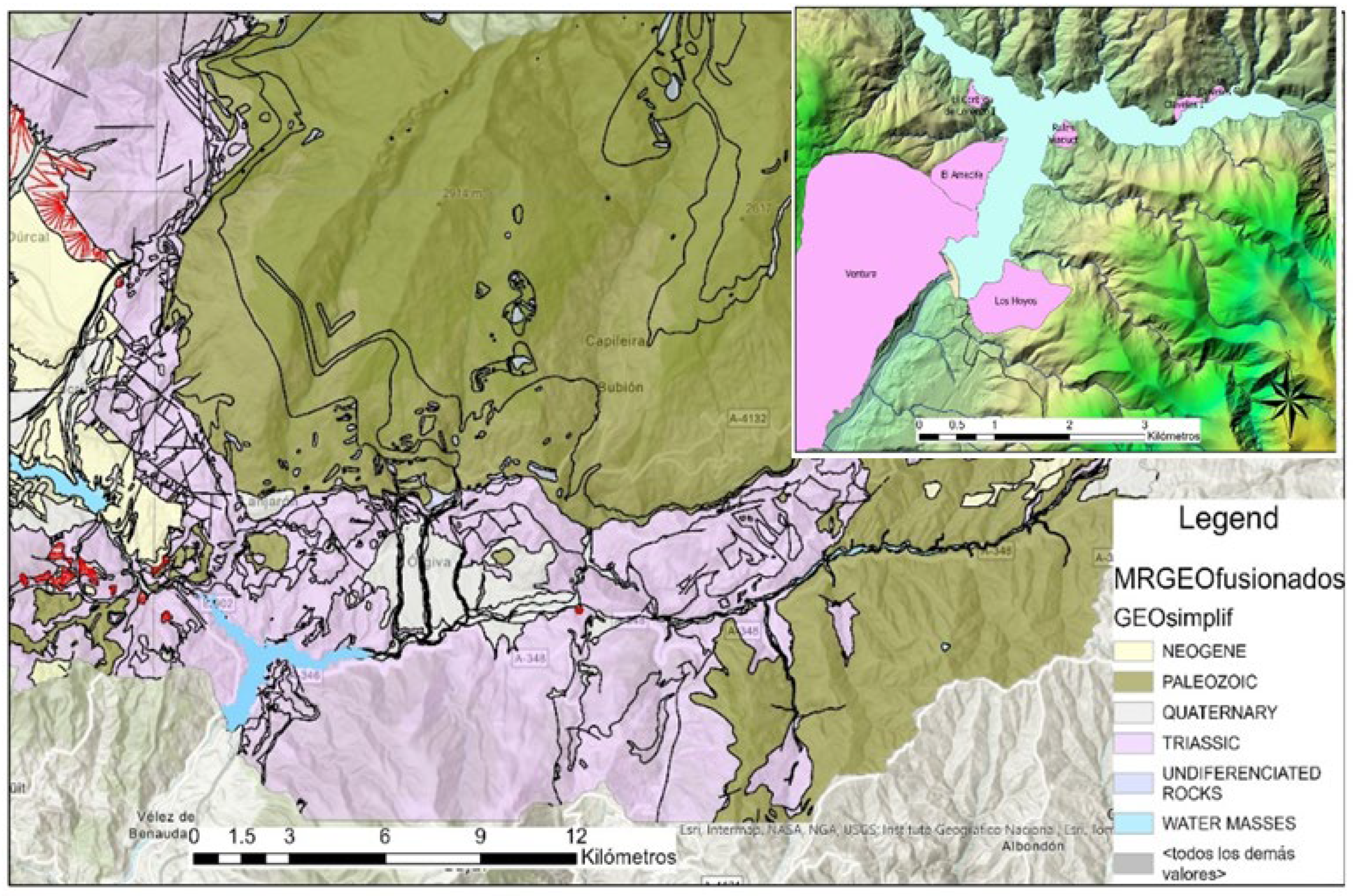
2.4. Geological Context and Main Landslides

From the geological point of view, the area surrounding the reservoir belongs to the Internal Zones of the Central Betic Cordillera, and the geology cartography was imported from the GEODES geological map of the area [59] (Figure 5).
In the slopes surrounding the Rules reservoir, some landslides have been identified [60,61,62], and the activity is being monitored using different techniques [63,64]. Earthquakes, changes in the water level of the reservoir, snowmelt, and extreme precipitation are the potential triggers for these landslides. Among these factors, Irigaray et al. [65] stated that the role of precipitation is a major factor in the damage when it is over 50% of the previous all-time record; nevertheless, recently, some stabilization periods have been detected after peak precipitation events due to the effect of lateral confining caused by the filling of the reservoir [63].
In the studied area, the main landslides have been identified: Ventura, El Arrecife, El Cortijo de Lorenzo, Los Claveles, and Rules Viaduct y Los Hoyos (Figure 5). Rules Viaduct and the Cortijo de Lorenzo are triggered with the changes in the reservoir water level drawdown periods—whereas El Arrecife, a translational landslide, presents a high potential for a collapse failure, and is showing a continuous movement [64].

3. Results

3.1. Results Type

As mentioned before, six deposition shape types were identified with their associated features (Table 1). The recognition of those shapes allowed us to quantify the consequences of a certain hydrological/hydraulic context of the water system. It is important to consider that the formation of those shapes is conditioned by the existence of the dam.
A quantitative assessment of each shape was developed (Table 1; Figure 6). The most predominant shape is Fas, with a total area of 0.86 km2 occupying 53.8% of the total studied area. Then, SFAs cover a total area of 0.67 km2, with 41.8% of the total analyzed area. The third most important shape according to aerial extension is VJs with 0.6 km2 and 3.6% of the total area. Finally, NVJs only cover 0.01 km2 with 0.8% of the total area.

3.2. Physical Interpretation of Shapes

Physical processes identification and interpretation were conducted to generate a robust equivalence between shapes and triggering processes. In this context, it is important to start by stating that in a normal and continuous regime (baseline), there is a generation of changing/dynamic erosive and depositional forms in the medium to long term (years) that must be considered. This normal regime is the one that maintains the forms or shapes that are described as follows.
  • Arc-Lines (dual changing upstream–downstream convexity): They are produced by slope friction, which involves a sediment deposition due to differential decrease in flow velocity. On one hand, convexity towards downstream that occurs at the reservoir tail shows a strong equivalence to the velocity profile in plants that usually follows a parabolic function (Figure 7). On the other hand, convexity towards upstream may be caused by the dam in the form of inverse flow and sediments’ transport process return. There is a change in string dimension between upstream and downstream AL due to return wave attenuation, flow velocity, and channel size. Consequently, the higher the flow velocity, the smaller the string cord that is produced. There is also a river stretch where the convexity of AL is not well defined, and it is quite uncertain (Figure 7). This is produced between the Ízbor junction and the reservoir tail on Guadalfeo River.
  • Breaking Lines: Lines marking the planes of high slope change.
  • Flat Areas: In times of stationary regime, finer materials form flat plateaus, close to the dam, due to the prevailing hydrostatic conditions.
  • Subflat Areas: When sediments are remobilized due to changing circumstances, especially a change in hydrodynamic conditions, a gentle slope gradient towards the dam is produced.
  • Vertical Jumps: These are produced predominantly in episodes of high sediment mobilization due to high flows and abrupt braking. A flood is produced in the entire section of the wadi and when the wavefront suddenly ceases to produce an effect, the process is paralyzed homogeneously throughout the section. Another reason may be the previous existence of natural or artificial promontories that act as a dam for the sediments.
  • Non-Vertical Jumps: These are produced when the vertical jumps are remobilized due to a change in hydrodynamic conditions. A steep gradient towards the dam is produced.

4. Discussion

This research was designed from an inductive perspective and it is a clear example of inverse engineering. Taking advantage of the detailed knowledge obtained from a bathymetric measurement campaign, the main triggering processes of sediment deposition were identified. The secondary goal of this research was to use its outcome to aid reservoir managers and constructers to exploit strategies to minimize the impact of sediment silting. Some of these applications based on the processes’ interpretation are briefly described as follows. Phenomena like Arc-Lines (ALs) with upstream convexity prove the real dam existence effect on the hydraulics and sediment dynamics, especially in extreme hydrological events. This also might aid in the design of the optimal location of dams’ bottom outlets. Furthermore, the occurrence of Vertical Jumps (VJs) and their dynamics can be used to better design the reservoir shape. The generation and occurrence of Flat and Subflat Areas (FAs, SFAs) could also be useful for identifying general hydrological and hydraulic patterns that may help to optimize the basin design. In general, these triggering processes depend on the dam/reservoir design and vice versa, which generates a dependent relationship that should be considered for minimizing reservoirs’ silting and optimizing their design and performance.

5. Conclusions

Large water reservoir silting is a worldwide problem that is becoming worse as the climate and meteorological conditions become more extreme. This is mainly because large events of sediments’ entrainment are produced in large hydrological events with high flow and occasional associated flooding processes. This research and paper comprise a physical processes identification and interpretation aimed at generating a robust equivalence between shapes and sediments’ transport triggering processes. This will allow, among other aspects, the implementation of more efficient preventive and corrective actions aimed at reducing sediments’ intake to the reservoirs. Furthermore, this research is expected to allow the implementation of interventions towards decreasing the absolute volume of existing sediments in the reservoir. Regarding the identified deposition shapes, the categories FAs and SFAs cover most of the studied area. This was largely interpretated as the sediments having reached a certain stability between formation and destruction.
The identification of BLs is very helpful to distinguish the different type of shapes. In this sense, the category ALs can be also understood as a special case of BLs. The convexity of ALs can be applied as an indicator of the level of roughness and sediments’ brake due to the interaction between flood plains and river banks. Furthermore, the ALs convexity direction can be useful for estimating the dam area influence on the flow transport process and for measuring the influence level. The latest can also be an estimator of dam stability due to sediment transport processes.
This research comprises a robust and complete geometrical modeling and analysis of bathymetric rivers and reservoir beds. This may be a limitation of this methodology if no funds are available.
Dam stability, as well as reservoir sustainability, might incorporate this methodology in their operational policies. In this sense, reservoirs’ operation rules might be recomputed to incorporate the results from this research. Consequently, interventions to release sediments from storage water could be more effective. Furthermore, the optimal design of hydroelectric plants and their associated pumping and turbine devices might incorporate some interpretations from this research.

Author Contributions

J.-L.M., F.E., S.Z. and C.P.-A. conceived, designed, and led the research. All authors made the research conceptualization and analytical development. T.D.-C. defined the forms of deposition. Geological issues were addressed by J.M.-M., J.N. and F.S., J.-L.M. supervised all actions. The Discussion and Conclusions sections were addressed by all authors, and all authors wrote the paper. All authors have read and agreed to the published version of the manuscript.

Funding

This research was partially developed within the framework of the SID_REDES project TED2021-129478B-I00, and SOGECAL project PID2022-142299OB-I00, both supported by the Ministry of Science and Innovation of Spain.

Data Availability Statement

Data are contained within the article.

Acknowledgments

The authors thank the University of Salamanca for the facilities made available to undertake this research.

Conflicts of Interest

The authors declare no conflicts of interest. The funders had no role in the design of the study; in the collection, analyses, or interpretation of data; in the writing of the manuscript; or in the decision to publish the results.

References

  1. Borland, D.C. Cap. 9 River Mechanics. In Reservoir Sedimentation; Shen, H.W., Ed.; Water Resources Publication: Fort Collins, CO, USA, 1971. [Google Scholar]
  2. Petkovsek, G.; Roca, M. Impact of reservoir operation on sediment deposition. In Proceedings of the Institution of Civil Engineers-Water Management; Thomas Telford Ltd.: London, UK, 2014; Volume 167, Issue 10, pp. 577–584. [Google Scholar]
  3. Gao, Q.; Li, Y.; Cheng, Q.; Yu, M.; Hu, B.; Wang, Z.; Yu, Z. Analysis and assessment of the nutrients, biochemical indexes and heavy metals in the Three Gorges Reservoir, China, from 2008 to 2013. Water Res. 2016, 92, 262–274. [Google Scholar] [CrossRef]
  4. Xu, M.; Dong, X.; Yang, X.; Chen, X.; Zhang, Q.; Liu, Q.; Jeppesen, E. Recent sedimentation rates of shallow lakes in the middle and lower reaches of the Yangtze River: Patterns, controlling factors and implications for lake management. Water 2017, 9, 617. [Google Scholar] [CrossRef]
  5. Schleiss, A.J.; Franca, M.J.; Juez, C.; De Cesare, G. Reservoir sedimentation. J. Hydraul. Res. 2016, 54, 595–614. [Google Scholar] [CrossRef]
  6. Ran, L.; Lu, X.X.; Xin, Z.; Yang, X. Cumulative sediment trapping by reservoirs in large river basins: A case study of the Yellow River basin. Glob. Planet. Chang. 2013, 100, 308–319. [Google Scholar] [CrossRef]
  7. Kokpinar, M.A.; Altan-Sakarya, A.B.; Kumcu, S.Y.; Gogus, M. Assessment of sediment yield estimations for large watershed areas: A case study for the Seyhan, Demirköprü and Hirfanlı reservoirs in Turkey. Hydrol. Sci. J. 2015, 60, 2189–2203. [Google Scholar] [CrossRef]
  8. Rahmani, V.; Kastens, J.H.; DeNoyelles, F.; Jakubauskas, M.E.; Martinko, E.A.; Huggins, D.H.; Gnau, C.; Liechti, P.M.; Campbell, S.W.; Callihan, R.A.; et al. Examining storage capacity loss and sedimentation rate of large reservoirs in the central US Great Plains. Water 2018, 10, 190. [Google Scholar] [CrossRef]
  9. González Rodríguez, L.; McCallum, A.; Kent, D.; Rathnayaka, C.; Fairweather, H. A review of sedimentation rates in freshwater reservoirs: Recent changes and causative factors. Aquat. Sci. 2023, 85, 60. [Google Scholar] [CrossRef]
  10. Molina, J.L.; Martos-Rosillo, S.; Martín-Montañés, C.; Pierce, S. The social sustainable aquifer yield: An indicator for the analysis and assessment of the integrated aquifers management. Water Resour. Manag. 2012, 26, 2951–2971. [Google Scholar] [CrossRef]
  11. Morris, G.; Fan, J. Reservoirs Sedimentation Handbook: Design and Management of Dams, Reservoirs and Watersheds for Sustainable Us; McGraw Hill: New York, NY, USA, 2010. [Google Scholar]
  12. Wang, G.; Wu, B.; Wang, Z.Y. Sedimentation problems and management strategies of Sanmenxia reservoir, Yellow river, China. Water Resour. Res. 2005, 41, W09417. [Google Scholar] [CrossRef]
  13. Reiser, D.W.; Ramey, M.P.; Wesche, T.A. Flushing flows. In Alternatives in Regulated River Management; CRC Press: Boca Raton, FL, USA, 2018. [Google Scholar]
  14. Doretto, A.; Bo, T.; Bona, F.; Apostolo, M.; Bonetto, D.; Fenoglio, S. Effectiveness of artificial floods for benthic community recovery after sediment flushing from a dam. Environ. Monit. Assess. 2019, 191, 88. [Google Scholar] [CrossRef]
  15. Patmont, C.; LaRosa, P.; Narayanan, R.; Forrest, C. Environmental dredging residual generation and management. Integr. Environ. Assess. Manag. 2018, 14, 335–343. [Google Scholar] [CrossRef] [PubMed]
  16. White, R. Evacuation of Sediments from Reservoirs; Thomas Telford: London, UK, 2001. [Google Scholar]
  17. Isaac, N.; Eldho, T.I. Sediment management studies of a run-of-the-river hydroelectric project using numerical and physical model simulations. Int. J. River Basin Manag. 2016, 14, 165–175. [Google Scholar] [CrossRef]
  18. Chaudhary, H.P.; Isaac, N.; Tayade, S.B.; Bhosekar, V.V. Integrated 1D and 2D numerical model simulations for flushing of sediment from reservoirs. ISH J. Hydraul. Eng. 2019, 25, 19–27. [Google Scholar] [CrossRef]
  19. Lai, Y.G.; Huang, J. Sediment modeling of hydraulic flushing: General guidelines, SEDHYD-2023. In Proceedings of the Sedimentation and Hydrologic Modeling Conference, St. Louis, MO, USA, 8–12 May 2023. [Google Scholar]
  20. Franco, A.; Moernaut, J.; Schneider-Muntau, B.; Strasser, M.; Gems, B. The 1958 Lituya Bay tsunami—Pre-event bathymetry reconstruction and 3D numerical modelling utilising the computational fluid dynamics software Flow-3D. Nat. Hazards Earth Syst. Sci. 2020, 20, 2255–2279. [Google Scholar] [CrossRef]
  21. Rose, N.L.; Morley, D.; Appleby, P.G.; Battarbee, R.W.; Alliksaar, T.; Guilizzoni, P.; Punning, J.M. Sediment accumulation rates in European lakes since AD 1850: Trends, reference conditions and exceedence. J. Paleolimnol. 2011, 45, 447–468. [Google Scholar] [CrossRef]
  22. Schiefer, E.; Petticrew, E.L.; Immell, R.; Hassan, M.A.; Sonderegger, D.L. Land use and climate change impacts on lake sedimentation rates in western Canada. Anthropocene 2013, 3, 61–71. [Google Scholar] [CrossRef]
  23. Zhao, Y.; Cao, W.; Hu, C.; Wang, Y.; Wang, Z.; Zhang, X.; Zhu, B.; Cheng, C.; Yin, X.; Liu, B.; et al. Analysis of changes in characteristics of flood and sediment yield in typical basins of the Yellow River under extreme rainfall events. Catena 2019, 177, 31–40. [Google Scholar] [CrossRef]
  24. Ahn, Y.S. Recent changes in sedimentation rate in three lakes of Ishikari Wetland, Northern Japan determined by 210Pb dating. Water Resour. 2018, 45, 795–802. [Google Scholar] [CrossRef]
  25. Pope, I.C.; Odhiambo, B.K. Soil erosion and sediment fluxes analysis: A watershed study of the Ni Reservoir, Spotsylvania County, VA, USA. Environ. Monit. Assess. 2013, 186, 1719–1733. [Google Scholar] [CrossRef]
  26. McCall, P.; Robbins, J.; Matisoff, G.J.C.G. 137Cs and 210Pb transport and geochronologies in urbanized reservoirs with rapidly increasing sedimentation rates. Chem. Geol. 1984, 44, 33–65. [Google Scholar] [CrossRef]
  27. Ruiz-Fernandez, A.; Paez-Osuna, F.; Urrutia-Fucugauchi, J.; Preda, M.J.C. 210Pb geochronology of sediment accumulation rates in Mexico City Metropolitan Zone as recorded at Espejo de los Lirios lake sediments. Catena 2005, 61, 3–48. [Google Scholar] [CrossRef]
  28. Daramola, J.; Adepehin, E.J.; Ekhwan, T.M.; Choy, L.K.; Mokhtar, J.; Tabiti, T.S. Impacts of land-use change, associated land-use area and runoff on watershed sediment yield: Implications from the Kaduna Watershed. Water 2022, 14, 325. [Google Scholar] [CrossRef]
  29. Nguyen, T.X.; Nguyen, B.T.; Tran, H.T.T.; Le, T.T.; Trinh, T.T.; Trinh, T.T.; Tu, M.B.; Cao, N.D.T.; Vo, H.D.T. The interactive effect of the season and estuary position on the concentration of persistent organic pollutants in water and sediment from the Cua Dai estuary in Vietnam. Environ. Sci. Pollut. Res. 2019, 26, 10756–10766. [Google Scholar] [CrossRef] [PubMed]
  30. Shrestha, B.; Maskey, S.; Babel, M.S.; van Griensven, A.; Uhlenbrook, S.J.C.C. Sediment related impacts of climate change and reservoir development in the Lower Mekong River Basin: A case study of the Nam Ou Basin, Lao PDR. Clim. Chang. 2018, 149, 13–27. [Google Scholar] [CrossRef]
  31. Chen, X.; Qiao, Q.; McGowan, S.; Zeng, L.; Stevenson, M.A.; Xu, L.; Huang, C.; Liang, J.; Cao, Y. Determination of geochronology and sedimentation rates of shallow lakes in the middle Yangtze reaches using 210Pb, 137Cs and spheroidal carbonaceous particles. Catena 2019, 174, 546–556. [Google Scholar] [CrossRef]
  32. Darama, Y.; Selek, Z.; Slek, B.; Ajgul, M.A.; Dagdeviren, M. Determination of sediment deposition of Hasanlar Dam using bathymetric and remote sensing studies. Nat. Hazards 2019, 97, 211–227. [Google Scholar] [CrossRef]
  33. Navas, A.; Valero-Garces, B.; Gaspar, L.; Machin, J. Reconstructing the history of sediment accumulation in the Yesa reservoir: An approach for management of mountain reservoirs. Lake Reserv. Manag. 2009, 25, 15–27. [Google Scholar] [CrossRef]
  34. Auel, C.; Albayrak, I.; Sumi, T.; Boes, R.M. Sediment transport in high-speed flows over a fixed bed: 1. Particle dynamics. Earth Surf. Process. Landf. 2017, 42, 1365–1383. [Google Scholar] [CrossRef]
  35. Serra-Llobet, A.; Kondolf, G.M.; Magdaleno, F.; Keenan-Jones, D. Flood diversions and bypasses: Benefits and challenges. WIREs Water 2022, 9, e1562. [Google Scholar] [CrossRef]
  36. Nilawar, A.P.; Waikar, M.L. Impacts of climate change on streamflow and sediment concentration under RCP 4.5 and 8.5: A case study in Purna river basin, India. Sci. Total Environ. 2019, 650, 2685–2696. [Google Scholar] [CrossRef]
  37. Wischmeier, W.H.; Smith, D.D. Predicting rainfall erosion losses. In USDA Agr. Res. Serv. Handbook, no. 537; USDA: Washington, DC, USA, 1978. [Google Scholar]
  38. Bouyoucos, G.J. The clay ratio as a criterion of susceptibility of soils to erosion. Agron. J. 1935, 27, 738–741. [Google Scholar] [CrossRef]
  39. MITECO. Ministerio para la Transformación Ecológica y el Reto Demográfico. Available online: https://www.miteco.gob.es/es/biodiversidad/servicios/banco-datos-naturaleza/informacion-disponible/inventario_nacional_erosion.html (accessed on 10 January 2024).
  40. Pudasaini, S.P.; Miller, S.A. The hypermobility of huge landslides and avalanches. Eng. Geol. 2013, 157, 124–132. [Google Scholar] [CrossRef]
  41. Yenes, M.; Monterrubio, S.; Nespereira, J.; Santos, G.; Fernández-Macarro, B. Large landslides induced by fluvial incision in the Cenozoic Duero Basin (Spain). Geomorphology 2015, 246, 263–276. [Google Scholar] [CrossRef]
  42. Franco, A.; Moernaut, J.; Schneider-Muntau, B.; Strasser, M.; Gems, B. Triggers and consequences of landslide-induced impulse waves—3D dynamic reconstruction of the Taan Fiord 2015 tsunami event. Eng. Geol. 2021, 294, 106384. [Google Scholar] [CrossRef]
  43. Panizzo, A.; De Girolamo, P.; Di Risio, M.; Maistri, A.; Petaccia, A. Great landslide events in Italian artificial reservoirs. Nat. Hazards Earth Syst. Sci. 2005, 5, 733–740. [Google Scholar] [CrossRef]
  44. SAIH-HIDROSUR. Available online: http://www.redhidrosurmedioambiente.es/saih/mapa/tiempo/real (accessed on 30 January 2024).
  45. Bladé, E.; Cea, L.; Corestein, G.; Escolano, E.; Puertas, J.; Vázquez-Cendón, E.; Dolz, J.; Coll, A. Iber-River modelling simulation tool. Rev. Int. Métodos Numéricos Para Cálculo Y Diseño Ing. 2014, 30, 1–10. [Google Scholar] [CrossRef]
  46. Wallingford, H.R. Measuring and Predicting Reservoir Volume Changes due to Sedimentation; User manual for RESSASS Version 1.5; HR Wallingford: Oxon, UK, 2001. [Google Scholar]
  47. Westrich, B.; Juraschek, M. Flow transport capacity for suspended sediment. In Proceedings of the 21st Congress IAHR, Melbourne, Australia, 19–23 August 1985. [Google Scholar]
  48. Ackers, P.; White, W.R. Sediment transport: New approach and analysis. J. Hydraul. Div. 1973, 99, 2041–2060. [Google Scholar] [CrossRef]
  49. Ali, M.; Sterk, G. Evaluation of sediment management strategies on reservoir storage depletion rate: A case study. Doboku Gakkai Ronbunshuu B 2010, 66, 207–216. [Google Scholar] [CrossRef]
  50. Lara, J.M.; Pemberton, E.L. Initial unit weight of deposited sediments. In Proceedings of the Federal Interagency Sedimentation Conference, Jackson, MI, USA, 28 January–1 February 1963; U.S. Dept. of Agriculture, Miscellaneous Publication No. 970. USDA: Washington, DC, USA, 1963; pp. 818–845. [Google Scholar]
  51. Cea, L.; Bladé, E. A simple and efficient unstructured finite volume scheme for solving the shallow water equations in overland flow applications. Water Resour. Res. 2015, 51, 5464–5486. [Google Scholar] [CrossRef]
  52. Roe, P.L. Discrete models for the numerical analysis of time-dependent multidimensional gas dynamics. In Upwind and High-Resolution Schemes; Springer: Berlin/Heidelberg, Germany, 1986; pp. 451–469. [Google Scholar]
  53. Hirano, M. River-bed degradation with armoring. In Proceedings of the Japan Society of Civil Engineers; Japan Society of Civil Engineers: Tokyo, Japan, 1971; Volume 1971, pp. 55–65. [Google Scholar]
  54. Sanz Ramos, M.; Cea Gómez, L.; Bladé i Castellet, E.; López Gómez, D.; Sañudo Costoya, E.; Corestein Poupeau, G.; Aragón Hernández, J.L. Iber v3: Manual de Referencia e Interfaz de Usuario de las Nuevas Implementaciones; International Centre for Numerical Methods in Engineering (CIMNE): Catalonia, Spain, 2022. [Google Scholar]
  55. Banasik, K.; Hejduk, L.; Krajewski, A.; Wasilewich, M. The intensity of siltation of a small reservoir in Poland and its relationship to environmental changes. Catena 2021, 204, 105436. [Google Scholar] [CrossRef]
  56. Xiang, L.; Lu, X.X.; Higgitt, D.L.; Wang, S.M. Recent lake sedimentation in the middle and lower Yangtze basin inferred from Cs-137and Pb-210 measurements. J. Asian Earth Sci. 2002, 21, 77–86. [Google Scholar] [CrossRef]
  57. Lemma, H.; Frankl, A.; Dessie, M.; Poesen, J.; Adgo, E.; Nyssen, J. Consolidated sediment budget of Lake Tana, Ethiopia (2012–2016). Geomorphology 2020, 371, 107434. [Google Scholar] [CrossRef]
  58. Mbatya, W.; Qayoom, L.A.T.; Sempewo, J.I. Assessment of reservoir sedimentation level and storage capacity using remotely sensed data for Namadope Reservoir in Luuka District, Uganda. In World Environmental and Water Resources Congress; American Society of Civil Engineers: Reston, VA, USA, 2019; pp. 30–42. [Google Scholar]
  59. Marín Lechado, C.; Roldán García, F.J.; Pineda Velasco, A.; Martínez Zubieta, P.; Rodero Pérez, J.; Díaz Pinto, G. Mapa Geológico Digital Continuo E. 1:50.000, Zonas Internas de las Cordilleras Béticas (Zona-2100). Available online: http://info.igme.es/cartografiadigital/geologica/geodezona.aspx?Id=Z2100 (accessed on 30 November 2023).
  60. Fernández, T.; Brabb, E.E.; Salazar, F.D.; Martin-Algarra, A.; Irigary, C.F.; Estevez, A.R.; Chacon, J. Rasgos geológicos y movimientos de ladera en el sector Izbor-Velez Benaudalla de la cuenca del Rio Guadalfeo (Granada). In Proceedings of the IV Simposio Nacional Sobre Taludes y Laderas Inestables (795–808), Granada, Spain, 11–14 November 1997. [Google Scholar]
  61. Jiménez, J.; Irigaray, C.; El Hamdouni, R.; Fernández del Castillo, T.; Chacón, J. Rasgos geomorfológicos y movimientos de ladera en la cuenca alta del Río Guadalfeo. In VI Simposio Nacional Sobre Taludes y Laderas Inestables; Corominas, J., Alonso, E., Ruiz, M.R., Ziegler, M.H., Eds.; Editorial Universitat Politècnica de València: Valencia, Spain, 2005; pp. 891–902. [Google Scholar]
  62. Chacón, J.; Irigaray, T.; Fernández, T. Los movimientos de ladera de la provincia de Granada. In Atlas Riesgos Naturales en la Provincia de Granada, 1st ed.; Ferrer, M., Ed.; Diputación de Granada-Geological Survey of Spain (IGME): Valencia, Spain, 2007; pp. 45–82. [Google Scholar]
  63. Reyes-Carmona, C.; Barra, A.; Galve, J.P.; Monserrat, O.; Pérez-Peña, J.V.; Mateos, R.M.; Notti, D.; Ruano, P.; Millares, A.; López-Vinielles, J.; et al. Sentinel-1 DInSAR for monitoring active landslides in critical infrastructures: The case of the Rules reservoir (Southern Spain). Remote Sens. 2020, 12, 809. [Google Scholar] [CrossRef]
  64. Reyes-Carmona, C.; Galve, J.P.; Moreno-Sánchez, M.; Riquelme, A.; Ruano, P.; Millares, A.; Teixidó, T.; Sarro, R.; Pérez-Peña, J.V.; Barra, A.; et al. Rapid characterisation of the extremely large landslide threatening the Rules reservoir (Southern Spain). Landslides 2021, 18, 3781–3798. [Google Scholar] [CrossRef]
  65. Irigaray, C.; Lamas, F.; El Hamdouni, R.; Fernández, T.; Chacón, J. The importance of the precipitation and the susceptibility of the slopes for the triggering of landslides along the roads. Nat. Hazards 2000, 21, 65–81. [Google Scholar] [CrossRef]
Figure 1. Case study location. Note: Iberian Peninsula map: Imagery © 2024 Landsat/Copernicus, Data SIO, NOAA, U.S. Navy, NGA, GEBCO, map data © 2024 Google, National Geographic Institute of Spain. Note: Hydrographic Demarcation of the Andalusian Mediterranean Basin map adapted by authors from SAIH-HIDROSUR [44].
Water 16 00960 g001
Figure 2. Itineraries followed during bathymetry (yellow lines) in the Rules reservoir (imagery © 2024 Landsat/Copernicus, Data SIO, NOAA, U.S. Navy, NGA, GEBCO, map data © 2024 Google, National Geographic Institute of Spain).
Water 16 00960 g002
Figure 3. General methodology.
Water 16 00960 g003
Figure 4. XYZ geometry cartography from bathymetric development.
Water 16 00960 g004
Figure 5. Simplified geological map of the area surrounding the Rules reservoir, from the GEODE IGME cartography [59], and (top right) active landslides located in the Rules reservoir.
Water 16 00960 g005
Figure 6. Spatial distribution of sediments depositional shapes.
Water 16 00960 g006
Figure 7. Sediment transport triggering processes interpretation inferred from shapes’ identification.
Water 16 00960 g007
Table 1. Spatial distribution of shapes type.
Shape TypeSurface (km2)/Length (m) % Surface/Length
Flat Areas0.8653.8
Subflat Areas0.6741.8
Non-Vertical Jumps0.010.80
Vertical Jumps0.063.60
Breaking Lines567.658.9
Arc-Lines396.641.1
Disclaimer/Publisher’s Note: The statements, opinions and data contained in all publications are solely those of the individual author(s) and contributor(s) and not of MDPI and/or the editor(s). MDPI and/or the editor(s) disclaim responsibility for any injury to people or property resulting from any ideas, methods, instructions or products referred to in the content.

