Article

Influence of SV Wave Oblique Incidence on the Dynamic Response of Arch Dams Under Canyon Contraction

1
Key Laboratory of Fluid and Power Machinery, Ministry of Education, Xihua University, Chengdu 610039, China
2
State Key Laboratory of Eco-hydraulics in Northwest Arid Region, Xi’an University of Technology, Xi’an 710048, China
*
Author to whom correspondence should be addressed.
Water 2024, 16(24), 3630; https://doi.org/10.3390/w16243630
Submission received: 4 November 2024 / Revised: 6 December 2024 / Accepted: 14 December 2024 / Published: 17 December 2024

Abstract

:
Current dynamic response analyses of arch dams under an oblique incidence of seismic waves have overlooked the effects of canyon contraction deformation. This study investigated the influence of the incident direction and incident angle of seismic waves on the comprehensive displacements, as well as the damage, of arch dams under canyon contraction conditions. When SV waves are incident obliquely along the river direction, the peak displacements of the dam crest and arch crown beam increase with increasing canyon contraction. The displacement of the dam reaches its maximum when the incident angle is 0°, indicating that the SV wave vertical incidence is the most unfavourable incidence mode affecting the displacement. Dam damage cracking is most severe in the case of a canyon contraction of 60 mm and an incidence angle of 0°. The dam damage cracking index in this case increases only by 7.6% compared to a canyon contraction of 0 mm and an angle of incidence of 0°. However, the change in canyon contraction when a seismic wave is incident obliquely can cause serious damage cracking to the dam. When the SV wave is incident obliquely along the cross-river direction, the dam damage cracking index in this case increases by 110% compared to the case where the canyon contraction is 0 mm, and the incidence angle is 0°. Therefore, it is necessary to comprehensively consider the influences of canyon contraction and the oblique incidence of seismic waves in the seismic design and safety review of arch dams.

1. Introduction

The western region of China is rich in hydropower resources, accounting for approximately 80% of total hydropower resources. The construction of high dams and large reservoirs serves as an important foundation for the development of hydroelectric energy. Owing to their adaptability to complex topographical conditions and strong load-bearing capacity, arch dams have been widely constructed in the western region. However, the western region is characterized by numerous active faults and high seismic intensity. Consequently, many arch dams must be planned and constructed in proximity to active faults and these dams face serious challenges to their seismic safety.
Many experts and scholars have researched the seismic performance of arch dams, but most of these works assume that seismic waves are vertically incident [1,2,3]. This assumption is commonly made for dam sites situated at a moderate distance from the seismic source. However, when the dam site is proximal to the seismic source, seismic waves tend to propagate obliquely [4,5]. Du et al. [6] analysed the dynamic response of arch dams when seismic waves are incident obliquely along river and cross-river directions. Their results show that the oblique incidence of seismic waves leads to an increase in the amplification coefficients of the spectral amplitudes of the displacements, velocities, and accelerations in the areas controlling the seismic safety of arch dams compared with a vertical incidence. Garcia et al. [7] examined the dynamic response of the Morrow Point dam under an oblique incidence of both plane P- and S-waves. Their study demonstrated that the dynamic response of an arch dam under seismic wave oblique incidence is considerably more pronounced than under vertical incidence. Consequently, disregarding the possibility of oblique incidence in the seismic design of dams could result in an overly optimistic assessment of their seismic safety margins. Zhang et al. [8] investigated the change rule of engineering demand parameters such as arch dam damage, dynamic displacement, and transverse joint opening with the incident angle when pulse and non-pulse seismic waves are incident obliquely along a cross-river direction and proposed a prediction model for the dynamic response of arch dams with different incident angles of seismic waves. Chen et al. [9] studied the seismic vulnerability of an arch dam with an SV wave incidence angle of 25°, taking the JP I arch dam as an analytical object, and calculated the probability of serious damage to the arch dam under design earthquakes and maximum credible earthquakes. Additionally, studies [4,9,10,11,12,13] have examined the influence of oblique incidence on the seismic responses of various hydraulic structures, including gravity dams, earth-rock dams, and hydropower plant structures. Collectively, these studies have reached the conclusion that there are marked differences in the dynamic responses of hydraulic structures under oblique incidence compared with vertical incidence. Therefore, it is necessary to consider the influence of seismic waves with oblique incidence in seismic safety analyses of hydraulic structures.
On the other hand, after reservoir impoundment, the canyon deforms under the influence of hydrogeological conditions such as seepage and temperature fields. Arch dam projects such as the Zeuzier dam in Switzerland [14] and the Beauregard dam in Italy [15] have reported that the structures were affected by canyon contraction. Wu et al. [16] collected field monitoring data from a total of 11 concrete arch and gravity dams and investigated the deformation response characteristics of upstream and downstream canyons and dams due to reservoir impoundment operations. For example, after the impoundment of the Jinping I and Xiluodu ultrahigh arch dam projects, the river canyons on both sides experienced particularly obvious contraction deformation. In recent years, the problem of canyon deformation in high arch dams has received increasing attention [17,18,19,20,21,22,23].
Yang et al. [24] focused on the influence of canyon contraction overload multipliers on the stress-strain state of dams at different water levels. Gao et al. [25] analysed the influence of canyon deformation on stress distribution in the Xiluodu arch dam and concluded that the Xiluodu arch dam has a large safety margin. Pan and Wang [26] investigated the influence of canyon deformation on the nonlinear dynamic response of the Xiluodu arch dam under strong earthquakes at the early stage of impoundment by establishing a finite element model of the arch dam–reservoir water–foundation system. Their results show that canyon contraction decreases damage at the base of the dam and increases damage at the dam shoulder, near the orifice, and in the upper middle of the downstream dam face near the dam shoulder. Therefore, the influence of canyon deformation on the seismic response of arch dams cannot be ignored.
In summary, both seismic wave oblique incidence and canyon contraction have a great influence on the seismic response of arch dams, but analyses of the seismic performance of arch dams in the near-fault region do not consider the influences of both simultaneously. Therefore, determining the influence of the seismic wave incidence angle on the dynamic response of arch dams under canyon contraction conditions is necessary. Section 1 of this paper is the introduction. Section 2 describes the finite element analysis (FEA) model for an arch dam and the simulation method for canyon contraction. Section 3 shows the displacement and damage response of the arch dam with changes in canyon contraction and incidence angles for SV waves incident obliquely along the river direction. Section 4 shows the displacement and damage response of the arch dam with changes in canyon contraction and incidence angles for SV waves incident obliquely along the cross-river direction. Section 5 contains the main conclusions.

2. Analysis Model

2.1. Finite Element Model of the Arch Dam–Foundation System

A hyperbolic arch dam is taken as the hypothetical object of analysis, with the horizontal arch ring of the dam adopting a variable-thickness parabola form. The thickness at the top of the arch crown beam is 8 m, whereas the thickness at the bottom is 34.5 m. The maximum dam height is 132 m, and the thickness-to-height ratio of the dam is 0.265. The foundation surface elevation of the dam is 433.3 m and the normal water level of the reservoir is 562.0 m. Modelling and numerical analysis are performed using Abaqus finite element software. Figure 1 shows the finite element model of the arch dam–foundation system, consisting of 68,087 elements and 67,368 nodes. The number of dam elements is 32,887 and the number of nodes is 27,038. Both the dam and the foundation are using a C3D8 element (eight-node hexahedral element).

2.2. Material Model

The strength grade of the main concrete for the arch dam is C30, with a concrete density of 2500 kg/m3 and a Poisson’s ratio of 0.167. The stress-strain relationship of the concrete is simulated using the concrete damaged plasticity (CDP) model [27,28]. In the static calculations, the elastic modulus of the concrete is 29.79 GPa, the static tensile strength ft is 2.1 MPa, and the static compressive strength fc is 20.1 MPa. Figure 2 shows the static uniaxial tensile and compressive stress-strain relationships as well as the damage curves of C30 concrete. In the dynamic calculations, the dynamic elasticity modulus of the concrete is taken as 1.5 times the static elasticity modulus according to the NB/T 35047-2015 Code for Seismic Design of Hydraulic Structures in Hydroelectric Engineering [29] to consider the strain rate effect. The dynamic compressive strength of concrete fcd is taken as 1.2 times the static compressive strength, fcd = 24.12 MPa. The dynamic tensile strength of concrete ftd is taken as 10% of the dynamic compressive strength, ftd = 2.41 MPa. Figure 3 shows the dynamic uniaxial tensile and compressive stress-strain relationships as well as the damage curves for C30 concrete. During the conversion from static to dynamic calculations, the transformation of the static-dynamic ontological model of concrete is realized through field variables. The bedrock foundation is a linear elastic material with a density of 2700 kg/m3. The elastic modulus is set at 10 GPa, and the Poisson’s ratio is 0.2.
When the damping effect of the arch dam–foundation system is considered, the Rayleigh damping model is adopted. The arch dam–foundation system has a first order self-oscillation frequency of 2.70 Hz and a second order self-oscillation frequency of 2.92 Hz. According to the Code for Seismic Design of Hydraulic Structures in Hydropower Engineering [29], the damping ratio of the arch dam is 5%. The Rayleigh damping coefficients are calculated based on the first two natural frequencies of the system: the mass damping coefficient α is equal to 0.634, and the stiffness damping coefficient β is equal to 0.004.

2.3. Static and Dynamic Loads

In the static analysis of arch dams, the main loads to be considered include self-weight, canyon contraction, hydrostatic pressure, and temperature load. Dynamic loads include hydrodynamic pressure and seismic load. The following discussion focuses on canyon contraction and seismic loading.
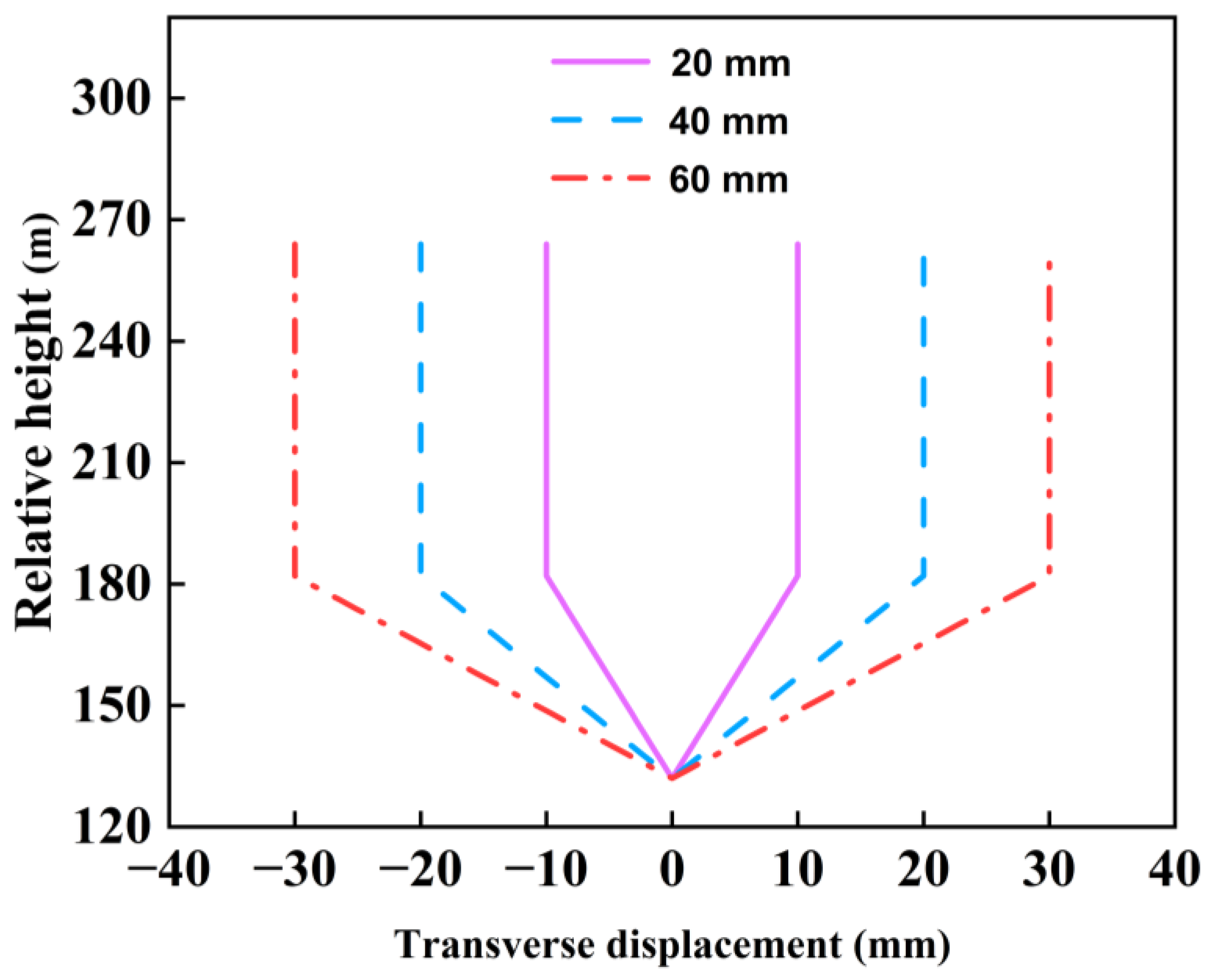
The main factors affecting valley contraction are rock creep, the cooling effect of reservoir water, and changes in seepage pressure within the rock. Thus, the magnitude of the valley contraction is the result of a combination of factors. The canyon contraction discussed in this paper refers to the deformation pattern (U-shaped distribution) of the Xiluodu project’s canyon contraction [30]. The monitoring data from reference [16] shows that below a certain elevation in the canyon of the Xiluodu dam site, the higher the canyon elevation, the greater the canyon contraction. There is no significant difference in canyon contraction values beyond this elevation. Figure 4 shows the distribution of canyon contraction along the elevation gradient. The degree of canyon contraction increases linearly with increasing elevation below 182 m, while above 182 m, the degree of canyon contraction remains constant. To consider the influence of canyon contraction on the dynamic response of the arch dam, this study simulates canyon contraction by applying nodal reaction forces to the contracting regions of the canyon. First, the displacement loads are applied to the contracting regions based on the canyon contraction pattern in Figure 4, and static calculations are performed to obtain the nodal reaction forces in the contracting regions. In the dynamic calculations, the displacement loads on the contracting regions are replaced with nodal reaction forces to simulate the effect of canyon contraction [31].

2.4. Seismic Load and Seismic Input Methods

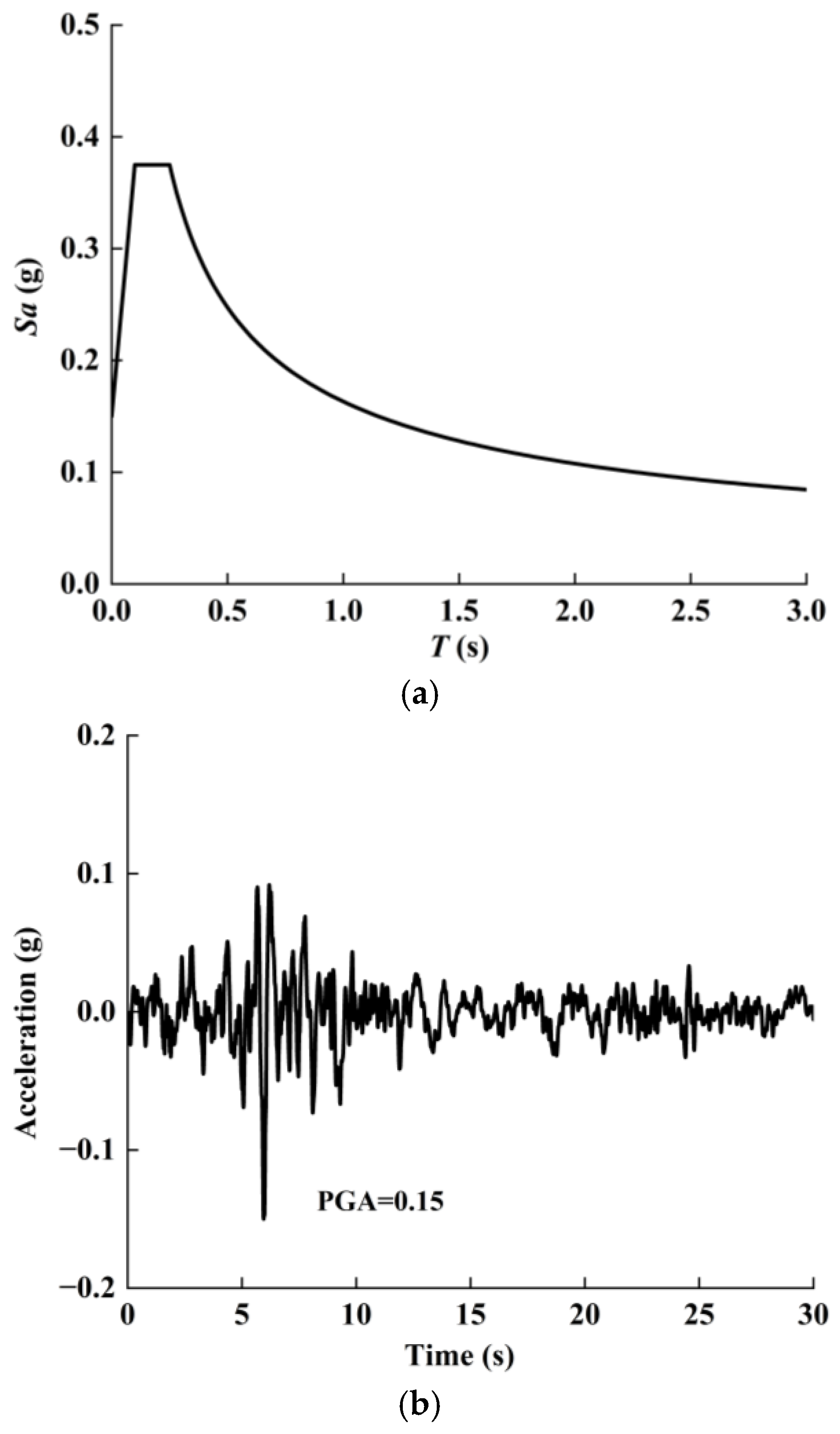
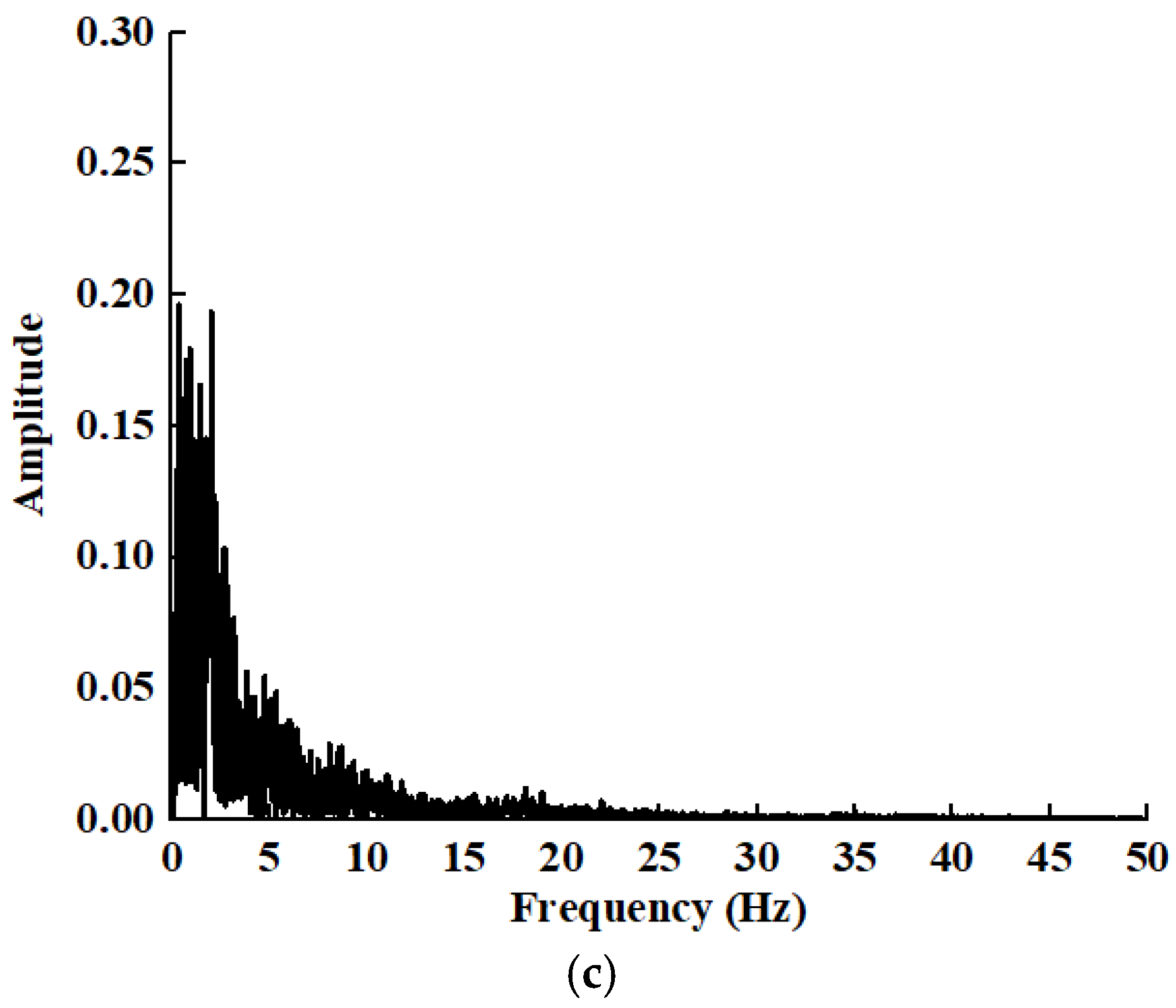
The standard design response spectrum is obtained based on the site characteristic cycle at the dam site and the maximum standard design response spectrum βmax corresponding to arch dams; the standard design response spectrum is used as the target spectrum, as shown in Figure 5a. The ground motion recorded by Chi-Chi earthquake station CHY029 is selected from the Pacific Earthquake Engineering Research Center’s strong earthquake database according to the target response spectrum. Figure 5b shows the acceleration time history of the input ground motion, with a peak ground acceleration (PGA) of 0.15 g and a duration of 30 s. Figure 5c shows the Fourier spectrum of this ground motion. The input method for the ground motion adopts the seismic wave input method for a combination of viscoelastic artificial boundaries and an equivalent nodal load [32]. The equivalent nodal load equation is as follows [33]:
F B f = ( K u B f + C u ˙ B f + σ B f ) A B ,
where K and C are the stiffness coefficient and damping coefficient matrices, respectively. When the normal direction of the boundary is parallel to the X-axis, K = diag [ K N K T K T ] , C = diag [ C N C T C T ] ; parallel to the Y-axis, K = diag [ K T K N K T ] , C = diag [ C T C N C T ] ; parallel to the Z-axis, K = diag [ K T K T K N ] , C = diag [ C T C T C N ] ; and the elements in the matrix are valued according to Equations (2) and (3). u B f = u x u y u z Τ , u ˙ B f = u ˙ x u ˙ y u ˙ z Τ , and σ B f are the free field displacement vector, free-field velocity vector, and free-field stress tensor on the boundary, respectively. AB is the affected area of the boundary node.
The spring stiffness K and damping coefficient C in the normal and tangential directions are as follows [34].
In the normal direction, they are as follows:
K N = 1 1 + A λ + 2 G R ,   C N = B ρ c P ,
In the tangential direction, they are as follows:
K T = 1 1 + A G R ,   C T = B ρ c S ,
where λ is the lame constant, G is the shear modulus, ρ is the density, R is the distance from the scattering source to the truncated boundary of the foundation, and the scattering source is located in the centre of the dam. A and B are the correction coefficients of the stiffness and damping coefficients, 0.8 and 1.1 [34], respectively.

3. SV Wave Obliquely Incident Along the River Direction

3.1. Influence of Canyon Contraction on the Static and Dynamic Comprehensive Displacement of Arch Dams Under SV Wave Obliquely Incident Along the River Direction

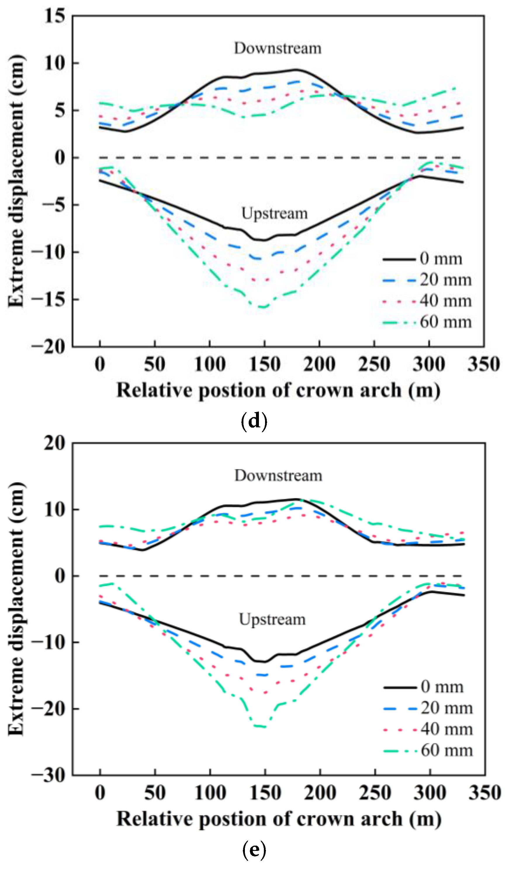
Figure 6 shows the extreme values of the static and dynamic comprehensive displacement of the dam crest in the river direction for different canyon contractions under SV waves obliquely incident along the river direction. The static and dynamic comprehensive displacement is the displacement of the dam crest relative to the dam foundation, and the “static and dynamic comprehensive displacement” is expressed as “displacement” to simplify the expression below. The displacement extremes of the dam crest exhibit a distribution pattern, with smaller displacements observed near the dam abutments and larger displacements in the middle of the arch ring. Owing to the arch effect, the displacement motion in the upstream direction of the dam crest is more pronounced. The canyon contraction increases, the displacement in the upstream direction in the middle of the dam crest increases, and the displacement near the dam shoulder in the upstream direction tends to decrease. The displacement in the downstream direction in the middle of the dam crest gradually decreases, whereas the displacement in the downstream direction near the dam shoulder tends to increase. The main reason for the middle and shoulder displacements of the dam crest showing this change rule with canyon contraction is that, on the one hand, as the amount of canyon contraction increases, the arch-directional thrust on both ends of the arch ring increases, resulting in an increase in the static displacement towards the upstream direction of the dam crest and ultimately leading to an increase in the static-dynamic comprehensive displacement towards the upstream direction of the dam crest. On the other hand, since the excavation surface of the dam shoulder tends towards the upstream riverbed, the static-dynamic comprehensive displacement towards the upstream direction near the shoulder is related mainly to the canyon contraction component along the excavation surface direction; therefore, as the canyon contraction increases its component along the excavation surface direction, it leads to an increase in the static-dynamic comprehensive displacement towards the downstream direction near the dam shoulder.
With an incident angle of 0°, the maximum static and dynamic comprehensive displacement in the upstream direction of the dam crest is 16.89 cm without canyon contraction. The maximum displacement of the dam crest increased by 9.95%, 23.95%, and 38.69% for contractions of 20 mm, 40 mm, and 60 mm, respectively, compared with that for no canyon contraction. The canyon contraction has a significant influence on the displacement of the dam crest. Similarly, under other incident angle conditions, the influence of canyon contraction on the displacement of the dam crest follows the same pattern as that for an incident angle of 0° but with a difference in the degree of influence. The influence of the incident angle on the displacement extremes of the dam crest is discussed in Section 3.2.
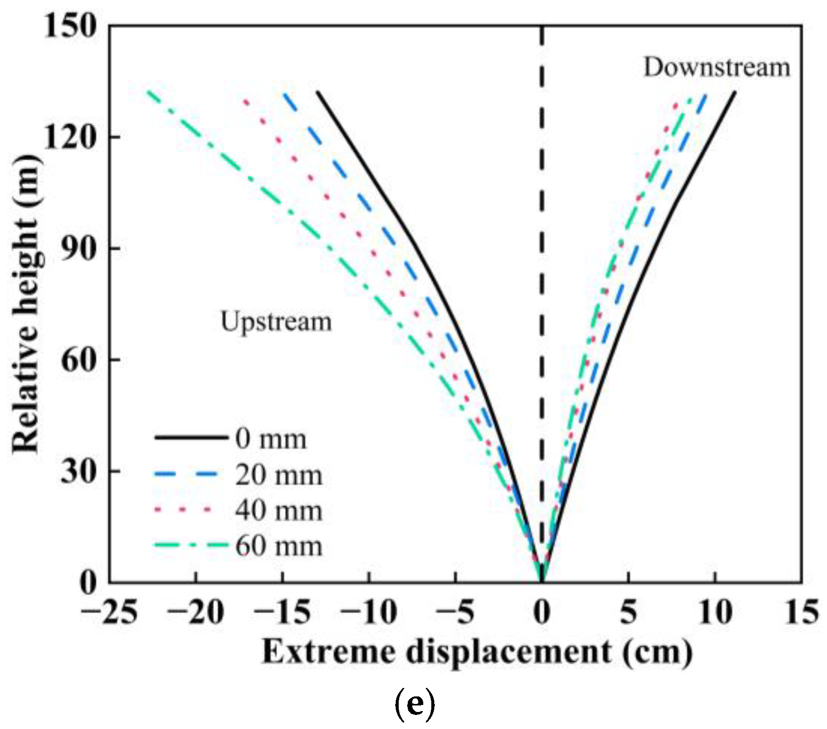
Figure 7 shows the static and dynamic comprehensive displacement extremes of the arch crown beam at different canyon contractions for SV waves obliquely incident along the river direction, indicating that the displacement of the arch crown beam increases with increasing dam height and that the displacement motion in the upstream direction is more significant. As canyon contraction increases, the displacement extremes in the upstream direction of the arch crown beam increase while the extremes in the downstream direction decrease.
With an incident angle of 0°, the maximum displacement of the arch crown beam upstream is 16.95 cm when there is no canyon contraction. Compared with the case without canyon contraction, the maximum displacements of the arch crown beam increase by 9.91%, 23.81%, and 38.51% when the canyon contraction is 20 mm, 40 mm, and 60 mm, respectively. This also indicates that, under the same incident angle conditions, the displacement upstream of the arch crown beam increases with increasing canyon contraction. The distribution patterns of the displacement of the dam crest and arch crown beam both suggest that canyon contraction significantly influences the static and dynamic comprehensive displacement of the arch dam.

3.2. Influence of the Incident Angle on the Static and Dynamic Comprehensive Displacement of the Arch Dam

Figure 6 and Figure 7 show that the distribution patterns of the comprehensive static and dynamic displacement extremes of the dam crest and arch crown beam are similar for different incidence angles, but there are notable variations in the specific values. To further investigate this influence, Figure 8 shows the variation in static and dynamic comprehensive displacement extremes of the arch dam with incident angle under the oblique incidence of SV waves along the river direction. Figure 8 shows that when the canyon contraction is the same, when the incidence angle is in the range of 0–35°, the displacement extremes upstream of the arch dam decrease while the displacement extremes downstream remain relatively unchanged. However, the displacement extremes in the upstream and downstream directions increase steeply in the range of 35–37° where the displacement in the downstream direction is always smaller than the displacement at an incidence angle of 0°. The change rule of displacement with incidence angle is consistent with the change rule of the amplification coefficient of surface ground motion with incidence angle [12]. That is, when the incident wave is known, the surface ground motion decreases with increasing incident angle in the range of 0–35°, and the surface ground motion increases significantly with increasing incident angle in the range of 35–37°.
Under the condition of no canyon contraction, the displacement extreme in the upstream direction of the arch dam is 16.89 cm at an incidence angle of 0° and the displacement extreme in the upstream direction is reduced by 14.57%, 51.09%, 55.68%, and 7.74% at incidence angles of 15°, 30°, 35°, and 37°, respectively, compared with an incidence angle of 0°. The displacement extreme in the downstream direction is 8.97 cm at an incidence angle of 0°. The displacement extremes in the downstream direction at incidence angles of 15°, 30°, 35°, and 37° increased by 5.02%, 0.22%, 3.57%, and 28.54%, respectively, compared with those at an incidence angle of 0°. The significant differences in the displacements under different incident angles indicate that the oblique incidence of seismic waves has a considerable influence on the displacement of the arch dam. When SV waves are incident obliquely along a river, vertical incidence is the most unfavourable incidence mode affecting the displacement of the arch dam.

3.3. Arch Dam Damage

The dynamic calculation results of the arch dam reveal that when the compressive damage factor of the dam is very small, the dam will not experience crushing failure. This paper primarily analyses the tensile damage of a dam under different conditions. When the tensile damage factor of a concrete element exceeds 0.8, the element can be considered to have experienced damage cracking [35]. To quantitatively evaluate the degree of damage cracking of the dam under different conditions, the degree of damage cracking is evaluated by the percentage of the number of elements with a tensile damage factor exceeding 0.8 to the total number of elements. This percentage is called the damage cracking index [36], as shown in Equation (4).
k = n m × 100
where k represents the damage cracking index, n represents the number of elements with a tensile damage factor greater than 0.8, and m represents the total number of elements in the dam.
Figure 9 shows the distribution of the damage cracking index of the arch dam under different incident angles and canyon contractions. Figure 9 indicates that as canyon contraction increases, the damage cracking index decreases slightly and then increases. As the incident angle increases, the damage cracking index decreases and then increases. The damage cracking index is the largest, 5.66, at a canyon contraction angle of 60 mm and an incidence angle of 0°, at which the dam is the most severely damaged and cracked. The damage cracking index is the lowest, only 0.37, at no canyon contraction and at an incidence angle of 35°, at which the dam is the least damaged and cracked.
Under the same incident angle, the change in canyon contraction has a significant influence on the damage cracking index. For example, the dam damage cracking index without canyon contraction is 5.26 at an incidence angle of 0°, 7.6% and 1.7% larger than the canyon contraction values of 20 mm and 40 mm, respectively, and 7.6% less than the canyon contraction value of 60 mm. The dam damage cracking index varies by 8% for different canyon contractions. The influence of canyon contraction on damage cracking in a dam is relatively small under seismic wave vertical incidence. However, at an incident angle of 30°, the damage cracking index of the dam without canyon contraction is 0.42, 16.7%, 73.8%, and 157.1% lower than with canyon contractions of 20 mm, 40 mm, and 60 mm, respectively. Unlike seismic wave vertical incidence, dam vibration at the same height position is not synchronized when seismic waves are obliquely incident but more prone to damage cracking under the thrust of the dam shoulder on both sides. The variation rule of dam damage cracking with valley contraction calculated in this paper is similar to that obtained by Pan et al. [26] and Yuan et al. [31] at a vertical incidence of seismic waves. That is, the variation in the dam damage cracking index with valley contraction is very small. However, Pan et al. [26] and Yuan et al. [31] did not study the effect of valley contraction on arch dam damage under an oblique incidence of seismic waves. It is found that the damage cracking index of the dam body varies significantly with valley contraction in the case of an oblique incidence of seismic waves in this paper. Therefore, a change in canyon contraction has a significant influence on damage cracking in a dam when seismic waves are obliquely incident. The dam damage cracking is more severe at a valley contraction of 60 mm. It is possible that the effects of the transverse joints were neglected leading to this phenomenon. This factor will be explored in detail in future studies. In addition, canyon contraction significantly influences the degree of damage cracking of the dam at incident angles of 15°, 35°, and 37°. The damage cracking index of the dam without canyon contraction is lower than that with canyon contractions of 20 mm, 40 mm, and 60 mm. The difference in the damage cracking indices of the dam under different canyon contraction rates ranges from 1% to 150%.
When the canyon contraction is unchanged, the incident angle also has a significant influence on the damage cracking index of the dam. When the canyon contraction is 20 mm, the damage cracking index of the dam is 4.89 at an incidence angle of 0°, and is 75%, 897%, 1153%, and 209% greater than that at incidence angles of 15°, 30°, 35°, and 37°, respectively.
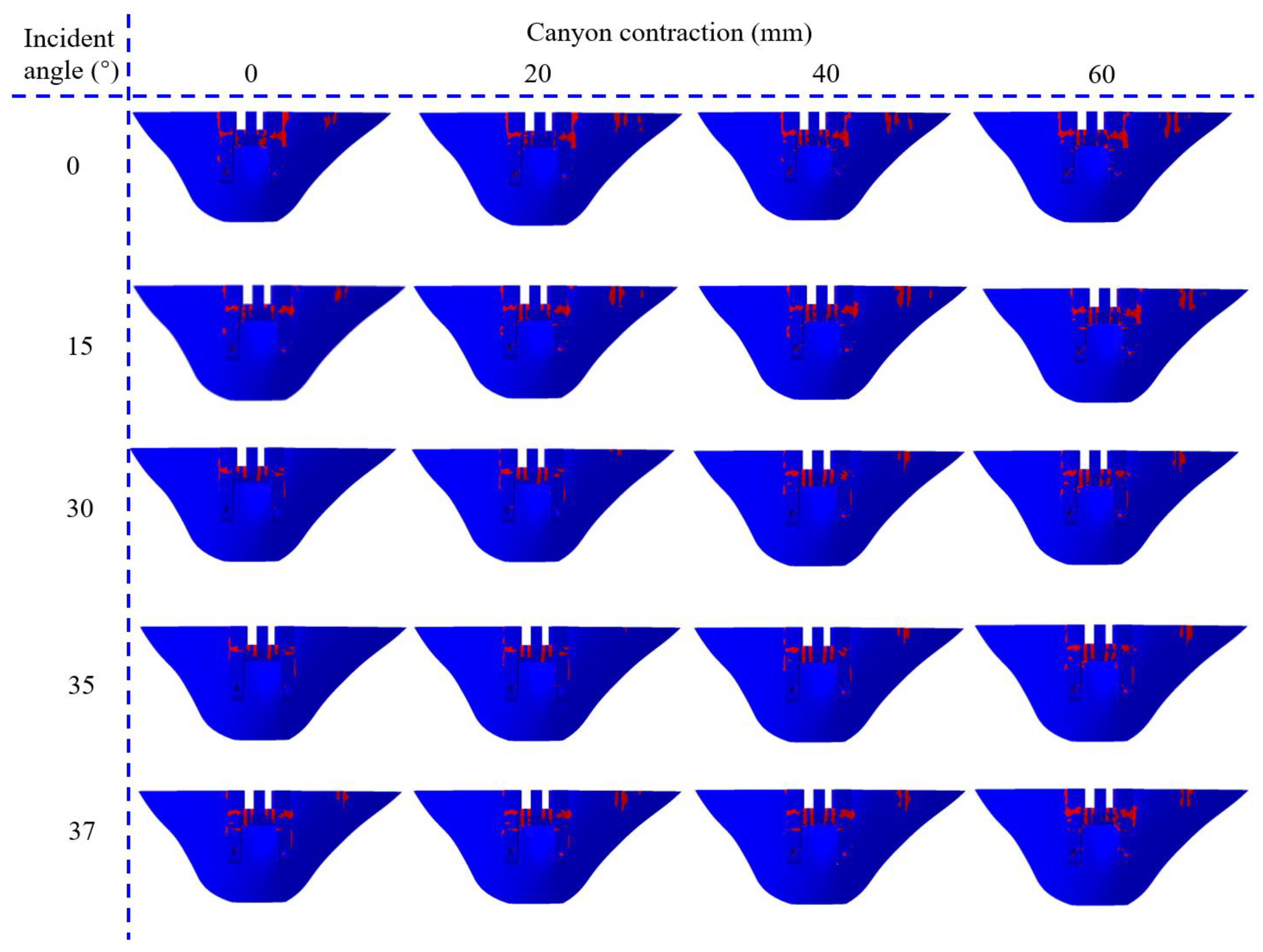
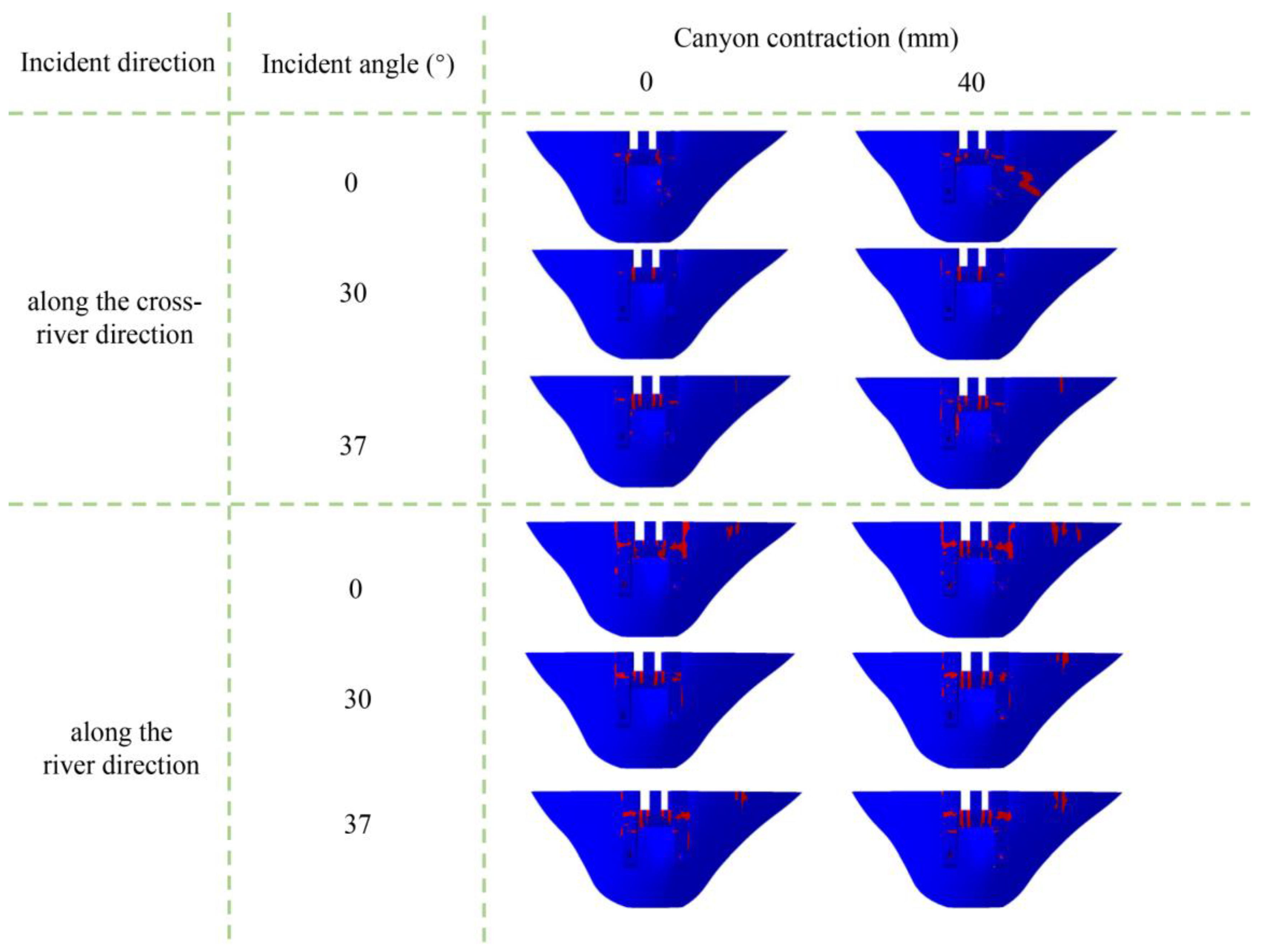
Figure 10 shows the damage cracking distribution of the arch dam under different conditions (upstream elevation view), and the red area represents damage cracking. Figure 10 shows that damage cracking, such as in the overflow surface outlets, gate piers, mid-level overflow holes, and the 1/4 arch ring on the right bank of the dam, mainly occurs in the parts of the geometry that suddenly change.

4. SV Wave Incidence Obliquely Along the Cross-River Direction

4.1. Influence of Canyon Contraction on the Static and Dynamic Comprehensive Displacement of Arch Dams Under SV Wave Incidence Obliquely Along the Cross-River Direction

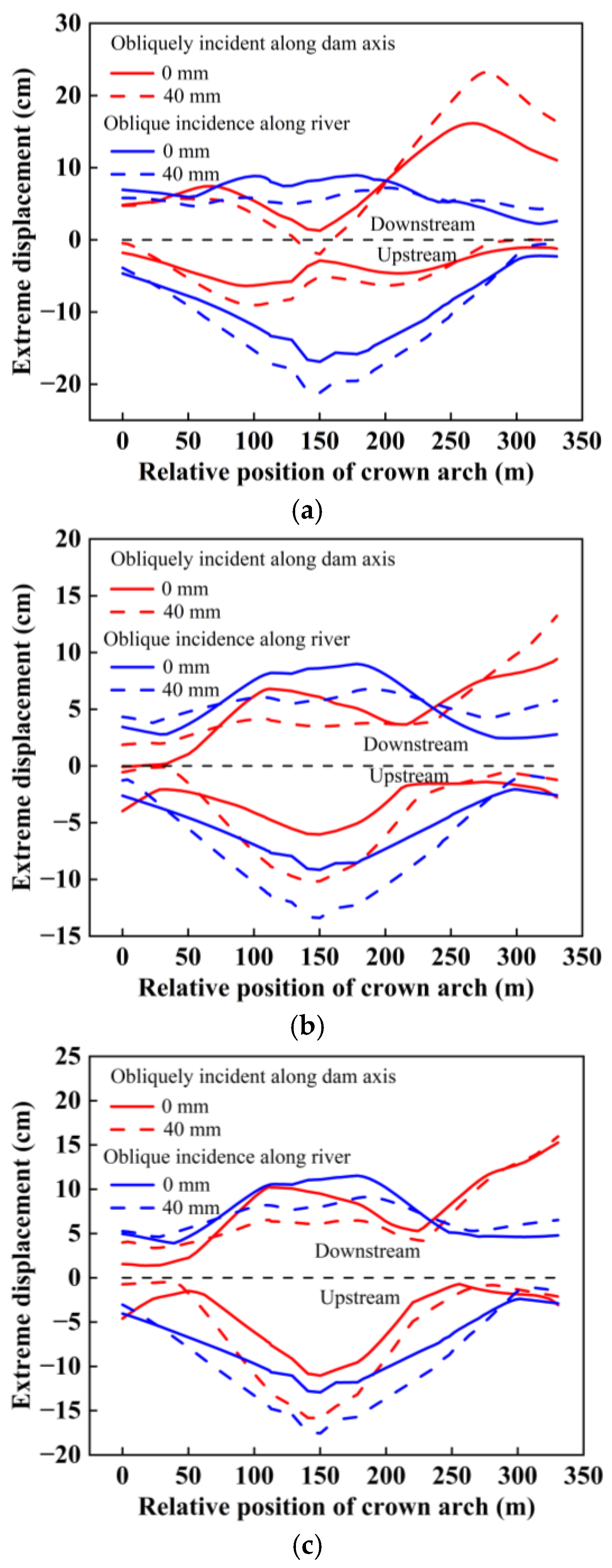
To analyse the influence of canyon contraction on the static and dynamic comprehensive displacement of the arch dam when SV waves are obliquely incident in the cross-river direction, Figure 11 shows the distribution of static and dynamic comprehensive displacement extremes of the dam crest. This section only presents the results for the two cases where the canyon contraction is 0 mm and 40 mm to save space. Additionally, the static and dynamic comprehensive displacement extremes of the dam crest under the SV wave along the river direction are provided for comparison. Figure 11 shows that the distribution pattern of the displacement extremes of the dam crest and the location of the maximum displacement change when the seismic wave is incident obliquely along the cross-river direction rather than obliquely along the river. The variations are as follows: the displacement of the dam crest in the upstream direction is approximately symmetrical about the middle of the dam crest and the displacement near the middle of the dam crest is greater. The displacement extremes in the downstream direction exhibit a small distribution pattern near the side of the incident wave (wave-facing side) and a large displacement pattern away from the side of the incident wave (wave-backing side), with the largest displacement occurring near the ¼ arch ring on the right side of the dam crest. The main reason for the maximum displacement of the dam crest occurring near the ¼ arch ring is that the incident wave from the left side of the canyon and the reflected wave from the right side of the canyon converge near the ¼ arch ring. As canyon contraction increases, the displacement of the middle of the dam crest in the upstream direction increases, and the displacement of both sides in the upstream direction decreases. While the displacement of the left side of the dam crest in the downstream direction decreases, the displacement of the right side in the downstream direction increases.
The maximum displacement of the dam crest in the downstream direction without canyon contraction is 16.14 cm at an incidence angle of 0°, 44.05% less than the maximum displacement when the contraction amount is 40 mm. Canyon contraction also has a significant influence on the displacement of the arch dam under obliquely incident conditions across the river.
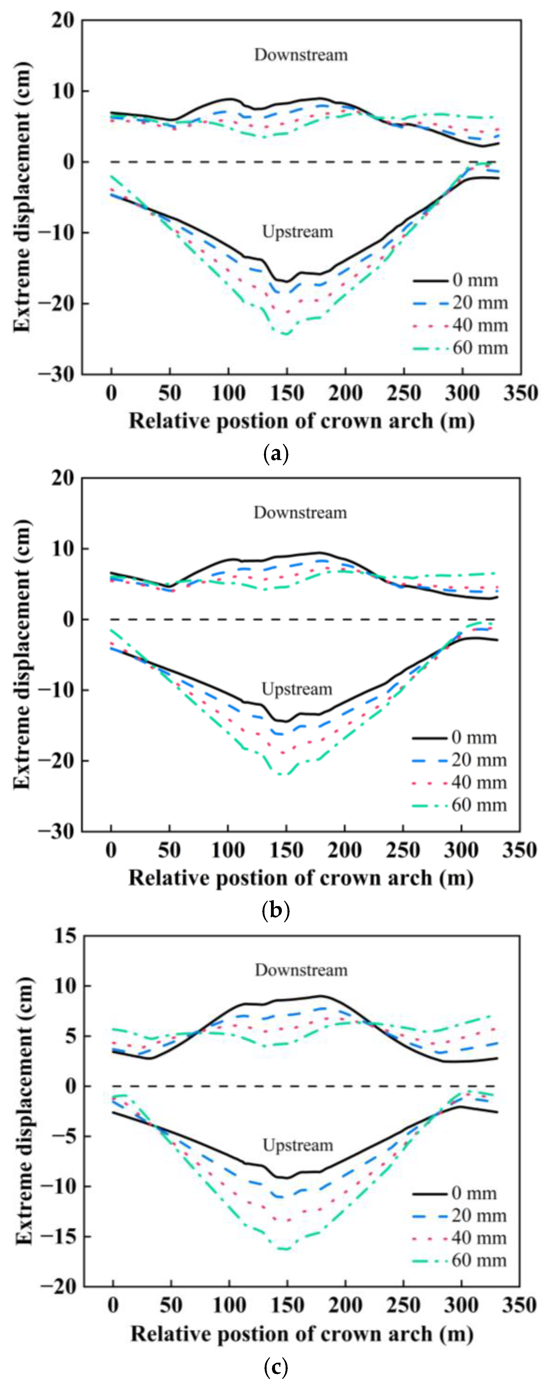
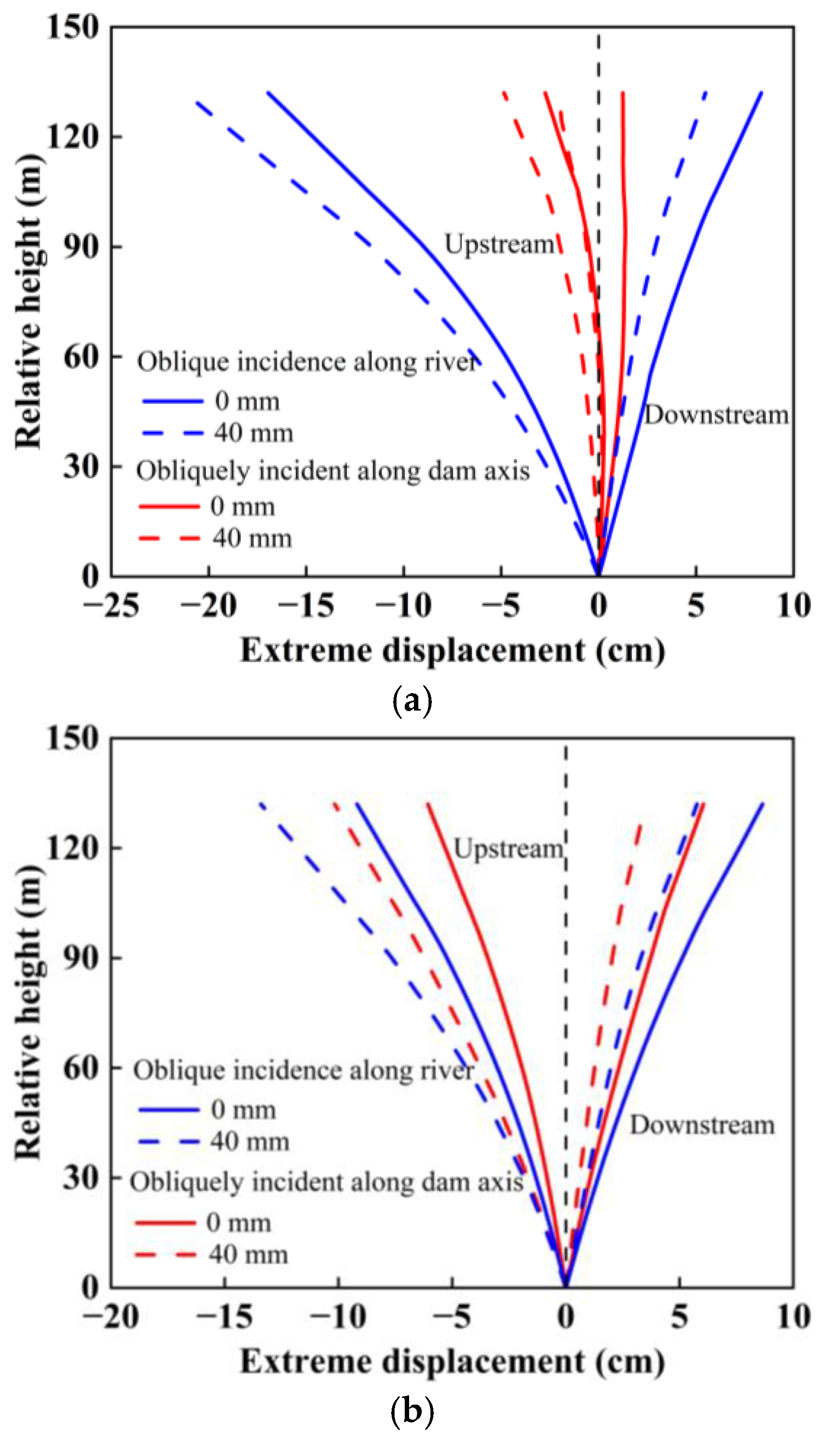
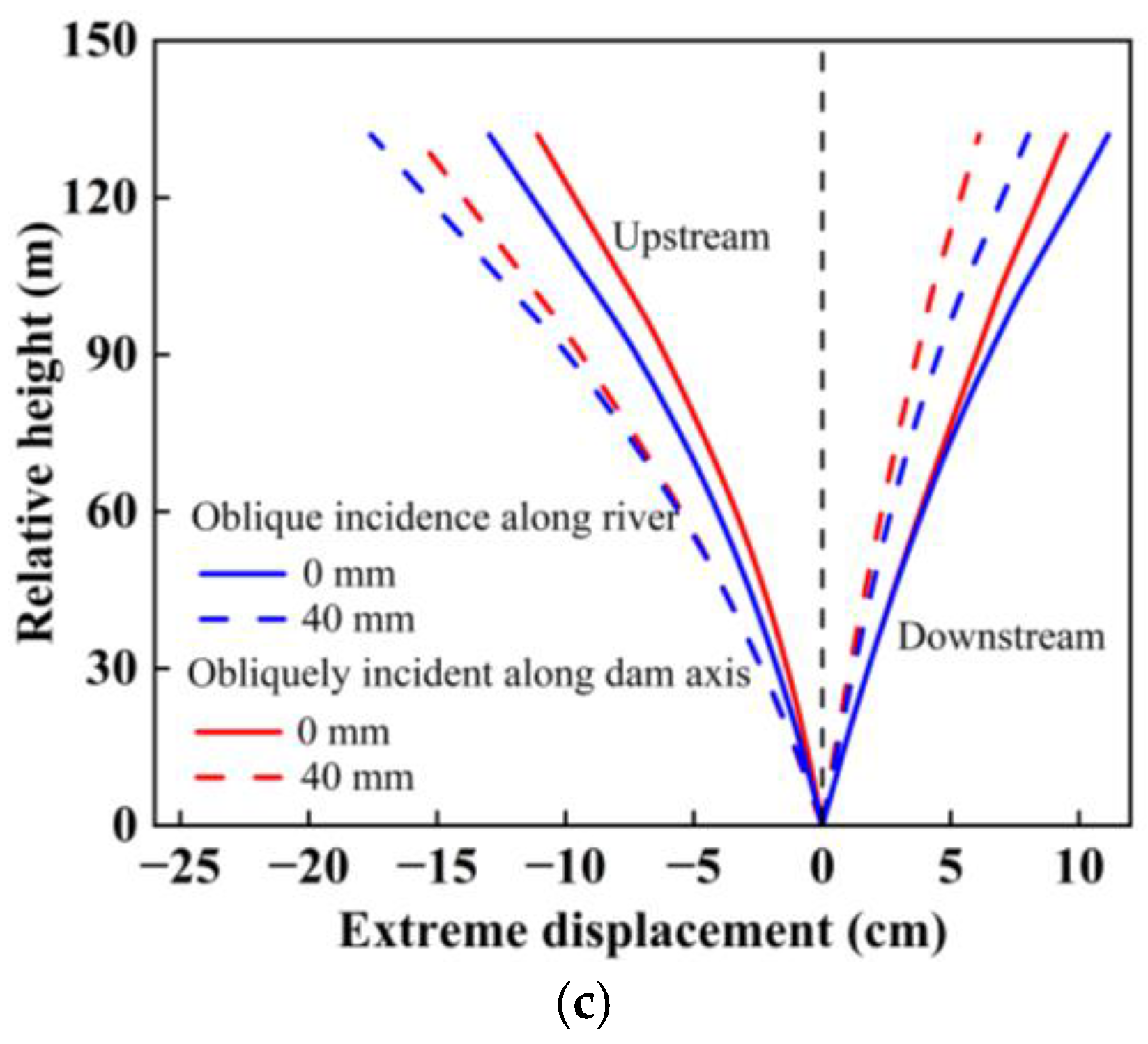
Figure 12 shows the distribution of static–dynamic comprehensive displacement extremes of the arch crown beam for different canyon contractions under SV wave incidence obliquely along the cross-river direction and the distribution of static–dynamic comprehensive displacement extremes under SV wave incidence obliquely along the river. Figure 12 shows that the displacement extremes of the arch crown beam under SV wave incidence obliquely along the cross-river area exhibit an increasing trend with increasing dam height, where the displacement extremes are more pronounced in the upstream direction. As canyon contraction increases, the displacement extremes of the arch crown beam increase in the upstream direction and decrease in the displacement extremes in the downstream direction. Since the stiffness in the direction of the cross-river area of the arch dam is greater than the stiffness in the direction of the river, the displacement of the arch crown beam under SV wave incidence obliquely along the cross-river direction is smaller than that under SV wave incidence obliquely along the river when the canyon contraction is the same and the incidence angle is the same.

4.2. Influence of the Incidence Angle on the Static and Dynamic Comprehensive Displacement of the Arch Dam

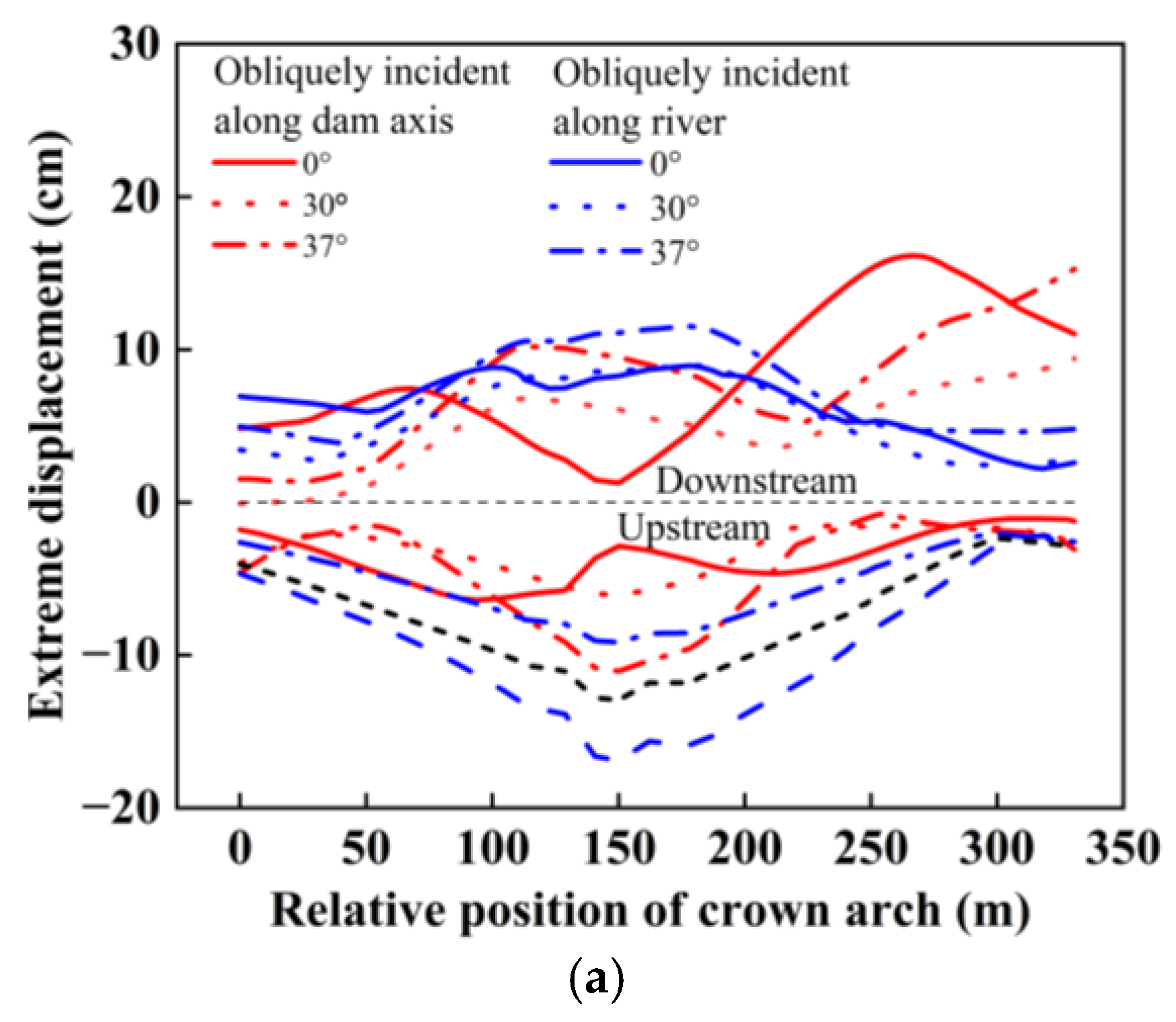
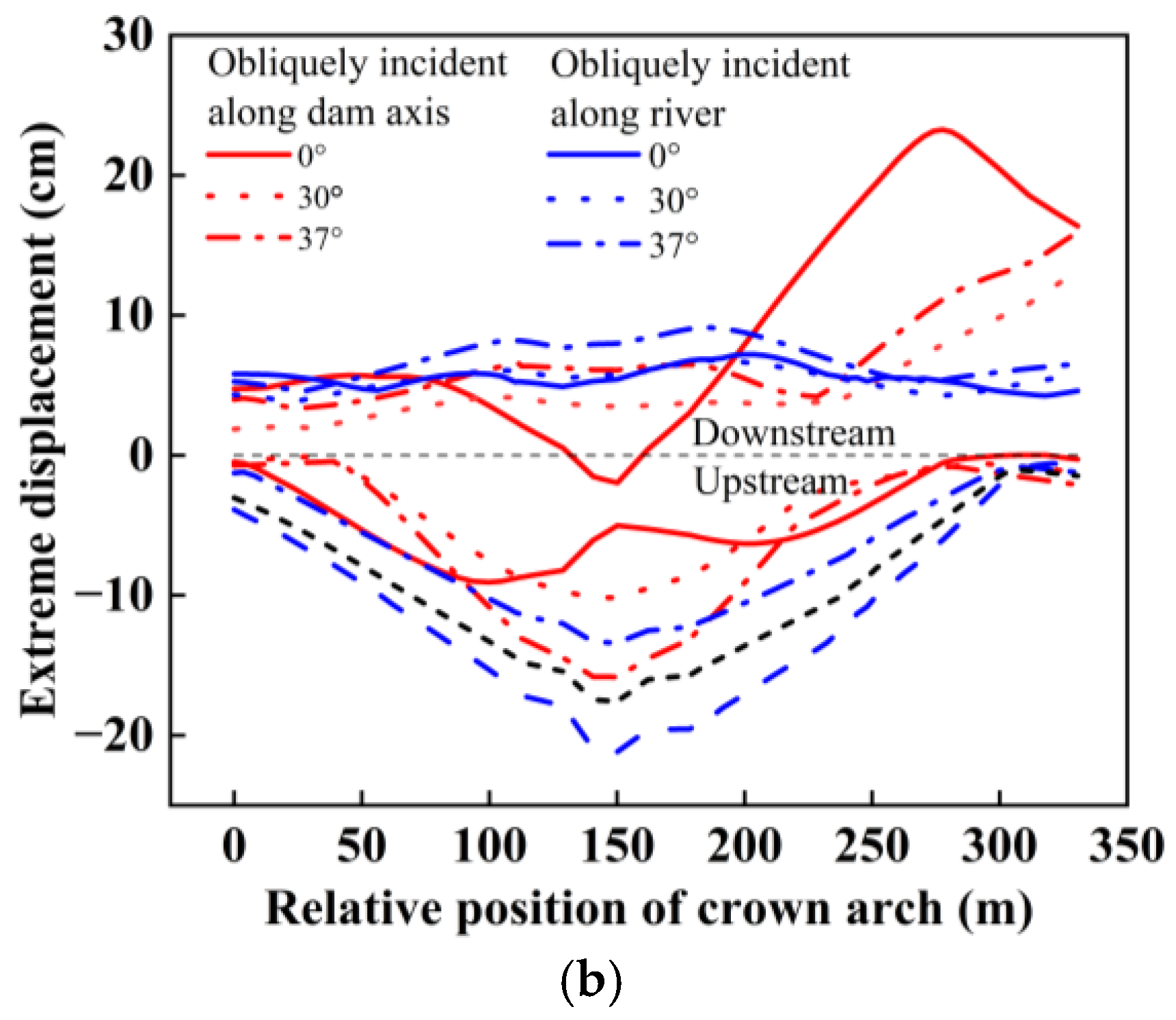
Figure 13 shows the distributions of the static and dynamic comprehensive displacement extremes of the dam crest at different incidence angles. Figure 13 shows that the static and dynamic comprehensive displacement extremes of the dam crest exhibit different distribution patterns at different incidence angles when seismic waves are obliquely incident across rivers. When the incidence angle is 0° the displacement of the dam crest in the upstream direction shows a pattern that is large near the 1/4 arch ring and small in the middle and at both ends, and the displacement in the downstream direction shows a small distribution pattern in the middle and a large distribution pattern at the right end. When the incidence angles are 30° and 37°, the displacement extremes of the dam crest in the upstream direction are large in the middle and small on both banks, and the displacement extremes in the downstream direction are small on the left bank and large on the right bank. The main reason for this distribution pattern is that the seismic wave is incident obliquely across the river and the incident seismic wave energy from the left bank and the seismic wave energy scattered from the right bank are superimposed near the 1/4 position of the arch ring on the right bank.
Figure 14 shows the distributions of the static and dynamic comprehensive displacement extremes of the arch crown beams when seismic waves are incident obliquely along the cross-river direction. The figure reveals that the variation pattern of the displacement extremes of the arch crown beam with the change in incident angle differs from that of seismic wave incidence obliquely along the river direction. The displacement extremes of the arch crown beam increase with increasing incidence angle under seismic wave incidence obliquely along the river direction. However, the displacement of the arch crown beam is smaller under seismic wave incidence obliquely in the cross-river direction than under seismic wave incidence obliquely in the river direction.

4.3. Influence of the Incident Direction on the Damage Cracking of Arch Dams

Figure 15 shows the distribution of the damage cracking of the arch dam given different incident directions, and the red area represents damage cracking. Figure 15 shows that the arch dam is prone to damage in the areas with sudden geometrical changes such as overflow surface outlets, gate piers, mid-level overflow holes, and the 1/4 arch ring on the right bank of the dam. The stiffness of the arch dam in the river direction is weaker than in the cross-river direction, and the deformation of the arch dam is greater when the seismic wave is incident obliquely along the river direction, so the damage to and cracking of the arch dam obliquely incident along the river direction are greater and the degree of cracking is more severe.
Table 1 presents the damage cracking indices of the arch dam under different incident directions. Table 1 shows that the variation rule for the dam damage cracking index with canyon contraction and incidence angle under SV wave incidence obliquely along the cross-river is similar to that under SV wave incidence obliquely along the river. The damage cracking index is much greater under SV wave incidence obliquely along the river than under SV wave incidence obliquely along the cross-river direction under the same canyon contraction and incidence angle conditions. When the incident angle is 0°, the damage cracking index of the arch dam under SV wave incidence obliquely along the river is 5.43 times (0 mm) and 2.53 times (40 mm) greater than under SV wave incidence obliquely along the cross-river direction. When the canyon contraction is 40 mm, the damage cracking indices of the arch dam under SV wave incidence obliquely along the river are 2.53 times (0°), 4.29 times (30°), and 3.29 times (37°) greater than under SV wave incidence obliquely along the cross-river direction, respectively.

5. Conclusions

This paper focuses on the problem of canyon contraction in the near-fault strong earthquake zone of southwestern China after an arch dam is filled with water. This paper simulates canyon contraction by applying a nodal reaction force at the interface between an arch dam and the canyon and studies the influence of SV wave incident angle changes on the dynamic response of the arch dam under canyon contraction conditions. The static and dynamic comprehensive displacements of typical parts and the damage to and cracking of the dam body are analysed given different canyon contractions and incident angles. Some valuable conclusions are obtained, and the main conclusions are as follows.
(1)
When SV waves are obliquely incident along a river, canyon contraction has a significant influence on the displacement of the dam crest and arch crown beam. The increase in canyon contraction results in an increase in the static and dynamic comprehensive displacements of the dam crest and arch crown beam. Compared with that under no canyon contraction, the maximum displacement of the dam crest and crown beam under the vertical incidence of seismic waves increased by 10%, 24%, and 39%, respectively, when the canyon contraction was 20 mm, 40 mm, and 60 mm.
(2)
When SV waves are obliquely incident along a river, the variation law of the maximum displacement of the arch dam with the incident angle is consistent with the variation law of the ground motion amplification factor at the surface with the incident angle. The maximum displacement of the arch dam decreases when the incident angle is within the range of 0~35° and sharply increases when the incident angle is within the range of 35~37°. However, the maximum displacement at each incident angle is smaller than that at an incident angle of 0°. These results indicate that the vertical incidence of SV waves is the most unfavourable incidence mode affecting the static and dynamic comprehensive displacements of arch dams.
(3)
When SV waves are obliquely incident along the river, the degree of damage to and cracking of the dam is most severe when the canyon contraction is 60 mm and the incident angle is 0°. The degree of damage and cracking of the dam is the lowest when the canyon contraction is 0 mm and the incident angle is 35°. In the first case, the damage and cracking index of the dam increased by 7.6% compared with the case where the canyon contraction was 0 mm and the incident angle was 0°. In the second case, it decreased by 13.2 times compared with the case where the canyon contraction is 0 mm, and the incident angle is 0°. The degree of dam damage varied greatly among the three cases. In addition, the change in canyon contraction under the vertical incidence of seismic waves has a relatively small influence on dam damage. Owing to the asynchronous motion of the same elevation dam under an oblique incidence of seismic waves along the river, the variation in canyon contraction under such conditions has a significant influence on the degree of damage to the dam. Therefore, it is necessary to consider the influence of canyon contraction on the damage to and cracking of a dam under an oblique incidence of SV waves.
(4)
The static and dynamic comprehensive displacement distribution of the dam crest under SV wave incidence obliquely along the cross-river direction is different from that under SV wave incidence obliquely along the river. The maximum displacement of the dam crest under SV wave incidence obliquely along the cross-river direction occurs near the wave-backing side of the dam shoulder. The maximum displacement of the middle part of the dam crest and the arch crown beam under the same canyon contraction and incidence angle is smaller than under SV wave incidence obliquely along the river, and the damage cracking index of the dam is also 2–5 times smaller than under SV wave incidence obliquely along the river.
(5)
Comprehensively considering the influences of canyon contraction and seismic wave oblique incidence on the seismic design and safety of arch dams in near-fault strong earthquake zones is necessary. The finite element model of the arch dam in this paper does not consider the transverse joints between the dam sections. In subsequent research, the influences of canyon contraction and seismic wave oblique incidence on the opening of transverse joints will be further analysed.

Author Contributions

Conceptualization, F.W.; Methodology, F.W.; Software, Z.Y. and Y.T.; Formal analysis, F.W. and Y.L.; Investigation, F.W., Z.Y. and Y.T.; Resources, Z.S.; Data curation, Z.Y.; Writing—original draft, Z.Y.; Writing—review & editing, F.W.; Visualization, Z.Y.; Supervision, X.L.; Project administration, F.W., Z.S. and Y.L.; Funding acquisition, F.W., Z.S. and Y.L. All authors have read and agreed to the published version of the manuscript.

Funding

This research was funded by [the Key Program of the National Natural Science Foundation of China] grant number [52039008]; [the Natural Science Foundation of Sichuan Province] grant number [24NSFSC4618]; [the Natural Science Basic Research Program of Shaanxi Province] grant number [2022JM-276].

Data Availability Statement

Some data and models that support the findings of this study are available from the corresponding author upon reasonable request, including the model of the arch dam finite element, and the numerical calculation data of the seismic analysis of the arch dam.

Acknowledgments

I would like to acknowledge Engineer Zhang Qian from Sichuan Water Development Investigation, Design & Research Co., Ltd. for providing the model data for this paper.

Conflicts of Interest

The authors declare that they have no known competing financial interests or personal relationships that could have appeared to influence the work reported in this paper.

References

  1. Chen, D.H.; Yang, Z.H.; Wang, M.; Xie, J.H. Seismic performance and failure modes of the Jin’anqiao concrete gravity dam based on incremental dynamic analysis. Eng. Fail. Anal. 2019, 100, 227–244. [Google Scholar] [CrossRef]
  2. Sadeghi, N.; Mirzabozorg, H. Safety analysis and seismic behavior of concrete arch dams (V&Ushaped dams). J. Civil Eng. Mater. Appl. 2023, 7, 169–183. [Google Scholar]
  3. Zhang, M.Z.; Wang, X.C.; Liu, Y.L.; Wang, J.T.; Yi, K.; Yan, J.H.; Chen, H.J. Effect of attached outlets on the dynamic response of arch dams. Eng. Struct. 2024, 302, 117392. [Google Scholar] [CrossRef]
  4. Zhang, J.W.; Li, M.C.; Han, S. Seismic analysis of gravity dam-layered foundation system subjected to earthquakes with arbitrary incident angles. Int. J. Geomech. 2022, 22, 04021279. [Google Scholar] [CrossRef]
  5. Fan, G.; Zhang, L.M.; Li, X.Y.; Fan, R.L.; Zhang, J.J. Dynamic response of rock slopes to oblique incident SV waves. Eng. Geol. 2018, 247, 94–103. [Google Scholar] [CrossRef]
  6. Du, X.L.; Xu, H.B.; Zhao, M. Analysis on seismic responses of high arch dam to SV waves of oblique incidence. J. Hydroelectr. Eng. 2015, 34, 139–145. (In Chinese) [Google Scholar]
  7. García, F.; Aznárez, J.J.; Padrón, L.A.; Maeso, O. Relevance of the incidence angle of the seismic waves on the dynamic response of arch dams. Soil Dyn. Earthq. Eng. 2016, 90, 442–453. [Google Scholar] [CrossRef]
  8. Zhang, T.R.; Xu, Q.; Chen, J.Y.; Li, J. Nonlinear seismic response and index correlation of high arch dams under cross-stream oblique incidence of near-fault SV waves based on wavelet decomposition. Soil Dyn. Earthq. Eng. 2023, 164, 107635. [Google Scholar] [CrossRef]
  9. Chen, D.H.; Pan, Z.Y.; Zhao, Y.Y. Seismic damage characteristics of high arch dams under oblique incidence of SV waves. Eng. Fail. Anal. 2023, 152, 107445. [Google Scholar] [CrossRef]
  10. Zhang, J.W.; Zhang, M.X.; Li, M.C.; Min, Q.L.; Shi, B.W.; Song, L.G. Nonlinear dynamic response of a CCRCC combined dam structure under oblique incidence of near-fault ground motions. Appl. Sci. 2020, 10, 885. [Google Scholar] [CrossRef]
  11. Song, Z.Q.; Wang, F.; Li, Y.L.; Liu, Y.H. Nonlinear seismic responses of the powerhouse of a hydropower station under near-fault plane P-wave oblique incidence. Eng. Struct. 2019, 199, 109613. [Google Scholar] [CrossRef]
  12. Wang, F.; Song, Z.Q.; Liu, Y.H.; Li, C.; Li, Z.G. Seismic response of embankment dams with asphalt concrete cores based on the three-dimensional time-domain inversion of ground motions. Int. J. Geomech. 2024, 34, 04024012. [Google Scholar] [CrossRef]
  13. Sun, B.B.; Wang, P.X.; Deng, M.J.; Fang, H.Y.; Xu, J.; Zhang, S.R.; Wang, C. Seismic performance assessment of hydraulic tunnels considering oblique incoming nonstationary stochastic SV waves based on the generalized PDEM. Tunn. Undergr. Space Technol. 2024, 143, 105481. [Google Scholar] [CrossRef]
  14. Ehrbar, H.; Bremen, R.; Otto, B. Gotthard base tunnel–tunnelling in the influence zone of two concrete arch dams. Geomech. Tunn. 2010, 3, 428–441. [Google Scholar] [CrossRef]
  15. Barla, G.; Antolini, F.; Barla, M.; Mensi, E.; Piovano, G. Monitoring of the Beauregard landslide (Aosta Valley, Italy) using advanced and conventional techniques. Eng. Geol. 2010, 116, 218–235. [Google Scholar] [CrossRef]
  16. Wu, M.X.; Jiang, H.; Zhang, C.H. General rules of dam-valley deformation due to reservoir impoundment. J. Hydroelectr. Eng. 2019, 38, 1–14. (In Chinese) [Google Scholar]
  17. Sun, G.H.; Lin, S.; Cheng, S.G.; Sun, T. Mechanisms of interaction between an arch dam and abutment slope using physical model tests. Rock Mech. Rock Eng. 2018, 51, 2483–2504. [Google Scholar] [CrossRef]
  18. Zhang, X.; Xiao, J.D.; Lin, Y.F.; Zhao, D.P. Valley deformation analysis for a high arch dam in Jinsha river, China. Arab. J. Geosci. 2021, 14, 1374. [Google Scholar] [CrossRef]
  19. Xu, L.D.; Rong, G.; Qiu, Q.Y.; Zhang, H.Q.; Chen, W.F.; Chen, Z.H. Analysis of reservoir slope deformation during initial impoundment at the Baihetan Hydropower Station, China. Eng. Geol. 2023, 323, 107201. [Google Scholar] [CrossRef]
  20. Rong, G.; Xu, L.D.; Yu, S.; Chen, W.F. The mechanism of large-scale river valley deformation induced by impoundment at the Baihetan Hydropower Station. Comput. Geotech. 2024, 165, 105898. [Google Scholar] [CrossRef]
  21. Li, M.W.; Zhou, Z.F.; Zhuang, C.; Zhou, Z.W. Deformation mechanism and model of river valley contraction of the Xiluodu reservoir, China. Environ. Earth. Sci. 2022, 81, 491. [Google Scholar] [CrossRef]
  22. Cheng, L.; Liu, Y.R.; Yang, Q.; Pan, Y.W.; Lv, Z. Mechanism and numerical simulation of reservoir slope deformation during impounding of high arch dams based on nonlinear FEM. Comput. Geotech. 2017, 81, 143–154. [Google Scholar] [CrossRef]
  23. Chai, D.; Cheng, H.; Mao, Y.P.; Zhang, G.X.; Yang, B.; Zhou, Q.J.; Liu, Y. Analysis of real deformation characteristics and influencing factors of ultra-high arch dam under action of valley shrinkage. Water Resour. Power. 2022, 40, 107–110. (In Chinese) [Google Scholar]
  24. Yang, X.C.; Gao, K.J.; Zhao, W.G.; Wang, R.K.; Zhang, J.H. Influence of valley deformation on safety of Xiluodu arch dam. J. Water Resour. Archit. Eng. 2018, 16, 72–78. (In Chinese) [Google Scholar] [CrossRef]
  25. Gao, K.J.; Zhao, W.G.; Wang, R.K.; Zhang, J.H. Influence of valley contraction on deformation and stress state of high arch dam. Sci. Technol. Eng. 2018, 18, 92–100. (In Chinese) [Google Scholar]
  26. Pan, J.W.; Wang, J.T. Effect of abutment movements on nonlinear seismic response of an arch dam. Struct. Infrastruct. E 2020, 16, 1106–1120. [Google Scholar] [CrossRef]
  27. Lubliner, J.; Oliver, J.; Oller, S.; Onate, E. A plastic-damage model for concrete. Int. J. Solids Struct. 1989, 25, 299–326. [Google Scholar] [CrossRef]
  28. Zhai, Y.F.; Zhang, L.J.; Cui, B.H.; Zhang, H.Y.; Ma, T.X. Evolution criteria of overall damage of concrete gravity dam body and foundation under near-fault ground motion. Structures 2022, 43, 594–605. [Google Scholar] [CrossRef]
  29. NB/T 35047-2015; Code for Seismic Design of Hydraulic Structures in Hydropower Engineering. CREEI China Renewable Energy Engineering Institute: Beijing, China, 2015. (In Chinese)
  30. Zhang, G.X.; Cheng, H.; Zhou, Q.J.; Liu, Y.Y. Analysis of mechanism of valley creep deformation of high arch dam during impoundment. China Sciencepaper 2019, 14, 77–84. (In Chinese) [Google Scholar]
  31. Yuan, R.; Qiu, Y.X.; Wang, J.T.; Shi, H.T. Effects of canyon contraction and reservoir stage on Xiluodu arch dam dynamic response. J. Hydroelectr. Eng. 2022, 41, 50–58. (In Chinese) [Google Scholar]
  32. Wang, F.; Song, Z.Q.; Liu, Y.H.; Li, C. Seismic response of a rockfill dam with an asphalt–concrete core under P waves with arbitrary incident angles. Int. J. Geomech. 2023, 23, 04023076. [Google Scholar] [CrossRef]
  33. Sun, B.B.; Deng, M.J.; Zhang, S.R.; Wang, C.; Du, M. Seismic performance assessment of high asphalt concrete core rockfill dam considering shorter duration and longer duration. Structures 2022, 39, 1204–1207. [Google Scholar] [CrossRef]
  34. Huang, J.Q.; Du, X.L.; Jin, L.; Zhao, M. Impact of incident angles of P waves on the dynamic responses of long lined tunnels. Earthq. Eng. Struct. Dyn. 2016, 45, 2435–2454. [Google Scholar] [CrossRef]
  35. Li, M.C.; Zhang, J.W.; Zhang, M.X.; Min, Q.L.; Shi, B.W. Plastic damage response analysis of concrete gravity dam due to obliquely incident seismic waves. J. Hydraulic Eng. 2019, 50, 1326–1338+1349. [Google Scholar]
  36. Pan, X.H.; Wang, G.H.; Lu, W.B.; Wang, Y.; Shu, Y.Z.; Zhang, X.Y. Blast performance and damage evaluation of high arch dams subjected to far-field underwater explosions: Consideration of joints. J. Struct. Eng. 2023, 149, 04022263. [Google Scholar] [CrossRef]
Figure 1. Arch dam–foundation finite element model.
Water 16 03630 g001
Figure 2. Static uniaxial tensile, compressive, and damage curves of the concrete. (a) Tension. (b) Compression.
Water 16 03630 g002
Figure 3. Dynamic uniaxial tensile, compressive, and damage curves of the concrete. (a) Tension. (b) Compression.
Water 16 03630 g003
Figure 4. U-shaped distribution of canyon contraction.
Water 16 03630 g004
Figure 5. Input ground motion. (a) Target response spectra. (b) Acceleration time history. (c) Fourier spectrum.
Water 16 03630 g005aWater 16 03630 g005b
Figure 6. Distribution of static and dynamic comprehensive displacement extremes of the dam crest in the river direction under different canyon contractions: (a) 0°; (b) 15°; (c) 30°; (d) 35°; and (e) 37°.
Water 16 03630 g006aWater 16 03630 g006b
Figure 7. Distribution of static and dynamic comprehensive displacement extremes of the arch crown beam in the river direction under different canyon contractions: (a) 0°; (b) 15°; (c) 30°; (d) 35°; and (e) 37°.
Water 16 03630 g007aWater 16 03630 g007b
Figure 8. Variation in the static and dynamic comprehensive displacement extremes of the arch dam with incidence angle. (a) Upstream. (b) Downstream.
Water 16 03630 g008
Figure 9. Damage cracking index of the arch dam.
Water 16 03630 g009
Figure 10. Distribution of damage cracking of the arch dam.
Water 16 03630 g010
Figure 11. Distribution of static and dynamic comprehensive displacement extremes of the dam crest under different canyon contractions when the SV wave incidence obliquely crosses the river: (a) 0°; (b) 30°; and (c) 37°.
Water 16 03630 g011
Figure 12. Distribution of static and dynamic comprehensive displacement extremes of the arch crown beam under different canyon contractions when the SV wave incidence obliquely crosses the river: (a) 0°; (b) 30°; and (c) 37°.
Water 16 03630 g012aWater 16 03630 g012b
Figure 13. Distribution of static and dynamic comprehensive displacement extremes of the dam crest under different incident angles: (a) 0 mm and (b) 40 mm.
Water 16 03630 g013aWater 16 03630 g013b
Figure 14. Distribution of static and dynamic comprehensive displacement extremes of the arch crown beam under different incident angles when the SV wave incidence obliquely crosses the river: (a) 0 mm and (b) 40 mm.
Water 16 03630 g014
Figure 15. Distribution of damage cracking in arch dams given different incident directions.
Water 16 03630 g015
Table 1. Damage cracking indices of arch dams with different incident directions.
Incident DirectionCanyon Contraction (mm)Incident Angle (°)
03037
cross-river00.970.160.59
402.040.170.62
river05.260.421.55
405.170.732.02
Disclaimer/Publisher’s Note: The statements, opinions and data contained in all publications are solely those of the individual author(s) and contributor(s) and not of MDPI and/or the editor(s). MDPI and/or the editor(s) disclaim responsibility for any injury to people or property resulting from any ideas, methods, instructions or products referred to in the content.