Article

Modeling Complex Interactions Between Acid–Rock Reactions and Fracture Propagation in Heterogeneous Layered Formations

1
State Key Laboratory of Shale Oil and Gas Enrichment Mechanisms and Effective Development, Beijing 102206, China
2
College of Energy and Mining Engineering, Shandong University of Science and Technology, Qingdao 266590, China
3
Research Center of Multiphase Flow in Porous Media, China University of Petroleum (East China), Qingdao 266580, China
*
Author to whom correspondence should be addressed.
Water 2024, 16(24), 3586; https://doi.org/10.3390/w16243586
Submission received: 20 November 2024 / Revised: 5 December 2024 / Accepted: 11 December 2024 / Published: 12 December 2024

Abstract

:
Acid fracturing is essential in enhancing recovery efficiency, especially within carbonate reservoirs. Although extensive studies have been conducted on hydraulic fracturing, understanding the intricate dynamics between acid–rock reactions and fracture propagation in heterogeneous layered reservoirs remains limited. This study employs a comprehensive coupled hydro-mechanical-chemical flow framework to investigate acid fracturing processes in layered geological formations. The model incorporates a two-stage homogenization approach to account for rock heterogeneity, a dual-scale continuum framework for fluid flow and acid transport, and a phase field method for examining fracture propagation. We thoroughly examine how treatment parameters, particularly acid concentration and injection rate, affect fracture propagation modes. The analysis identifies three distinct propagation patterns: crossing, diversion, and arresting. These are influenced by the interplay between pressure buildup and wormhole formation. Initially, higher acid concentration aids in fracture crossing by lowering the peak pressure required for initiation, but excessive concentration results in arresting because it causes extensive wormhole development, which reduces fluid pressure. Similarly, the injection rate plays a crucial role in fracture movement across layer interfaces, with moderate rates optimizing propagation by balancing pressure and wormhole growth. This comprehensive modeling framework serves as a valuable prediction and control tool for acid fracture behavior in complex layered formations.

1. Introduction

Acid fracturing is an essential well stimulation strategy used to improve hydrocarbon recovery in carbonate reservoirs, particularly those characterized by complex geological heterogeneity and low permeability. The effectiveness of acid fracturing treatments is significantly influenced by the interaction between acid–rock reactions, the mechanical properties of various layers, and in situ stress conditions. Understanding the mechanisms governing acid fracture propagation in heterogenous layered formations is key to advancing treatment design.
The interaction between fractures and geological interfaces has been extensively studied through various approaches [1,2,3,4]. From a mechanical perspective, the significance of mechanical properties and stress conditions has been comprehensively analyzed. Zhang et al. [5] employed a 3D hydro-mechanical coupling model, revealing the effects of bedding planes and property contrasts on fracture containment through shear failure mechanisms. Their research demonstrated that stress barriers and modulus differences between layers play a critical role in governing fracture height growth. Similarly, Guo et al. [6] employed a cohesive zone approach to demonstrate that fracture penetration across interfaces depends significantly on stress conditions and fluid properties, highlighting the substantial energy requirements for cross-layer propagation. Yang et al. [7] carried out experiments to explore the hydraulic fracturing process in shale–sandstone interbedded reservoirs under true triaxial compression. Their study revealed that the sandstone proportion significantly influences the fracture propagation, with larger sandstone layers facilitating easier fracture penetration. These findings align with Tan et al.’s three-dimensional cohesive zone model [8], which classified fracture geometries based on geological layer properties and in situ stresses, offering significant insights for treatment design in complex formations. Liu et al. [9] explored the impact of coal macro lithotypes on hydraulic fracturing in coalbed methane (CBM) reservoirs, revealing that the mechanical properties and interface strength of coal macro lithotypes significantly influenced fracture geometry and propagation.
Furthermore, the importance of optimizing treatment parameters for specific geological conditions is highlighted. Wang et al. [10] combined triaxial fracturing experiments with numerical simulations to examine fracture morphology in multilayered formations, emphasizing the impacts of fracturing fluid viscosity and injection parameters on fracture height growth. He et al. [11] conducted laboratory experiments to investigate fracture extension in multi-layered rocks, revealing that high-viscosity fluids facilitate vertical fracture propagation across multiple layers, reducing complexity in shale and enabling fractures to penetrate interfaces more effectively. Huang et al.’s two-dimensional FEM-DFN model showed that proper fluid viscosity optimization could enhance fracture height growth and complexity, leading to improved stimulation outcomes [12]. Lyu et al. [13] investigate the fracture propagation behavior in sandstone-shale interbedded reservoirs using multi-cluster hydraulic fracturing, revealing that differential stress and fracturing fluid viscosity significantly influence fracture initiation and propagation, with shale layers exhibiting lower fracture height compared to sandstone. Advanced simulation techniques have further enhanced our understanding of complex fracture systems [14,15,16,17]. Mao et al. [18] developed an integrated simulator coupling fracture propagation with proppant transport models, providing more accurate predictions of treatment outcomes in multilayer reservoirs. Aimene et al. [19] introduced a novel Material Point Method combined with anisotropic damage mechanics, providing more accurate predictions of fracture behavior in layered formations. Li et al. [20] utilized the peridynamics method to explore how loading parameters affect gas fracture propagation in layered medium, revealing that increased loading rates enhance radial fracture formation while diminishing the impact of stress. One notable strength of the peridynamics method is its inherent capability to model crack propagation without requiring explicit tracking of the sharp boundaries that separate damaged regions from intact ones. This feature makes it particularly effective for accurately resolving intricate fracture processes, such as crack-tip dynamics and discontinuities. Moreover, peridynamics has demonstrated considerable versatility in addressing multiphysics problems, including the coupling of thermal, fluid, and mechanical phenomena, as emphasized in recent research [21]. In contrast, this study employs the phase field method, which provides a robust and systematic framework for simulating complex fracture behaviors with excellent numerical stability. The method is particularly well-suited for analyzing the overall fracture evolution across a domain. Since our research focuses on understanding general fracture propagation patterns rather than capturing localized crack-tip phenomena, this method aligns effectively with the objectives of our work.
Although substantial advancements have been achieved in the study of hydraulic fracture propagation, research focusing specifically on acid fracture propagation in layered reservoirs remains relatively limited. The process of acid fracturing is further complicated by acid–rock reactions, which alter the mechanical properties of the rock and affect the trajectories of fracture propagation. Xu et al. [22] developed a comprehensive thermo-hydro-mechanical-chemical (THMC) framework to simulate acid fracturing that revealed the critical influence of acid parameters and natural reservoir parameters on fracture propagation and etching patterns. Kong et al. [23] investigated optimization strategies for acid injection parameters in tight carbonate reservoirs, demonstrating the importance of proper treatment design for enhancing fracture conductivity and extending etching lengths. Gou et al. [24] studied how variable viscosity acid impacts the morphology and conductivity of etched fractures in ultra-deep carbonate reservoirs, demonstrating that alternating injections of acids with low and high viscosities significantly enhance fracture conductivity compared to single viscosity systems. Zhu et al. [25] introduced a virtual bond method to model acid fracturing in carbonate formations, allowing the simulation of extensive fracture propagation. We have presented a hydro-mechano-reactive flow coupled model to study acid fracture propagation in a heterogeneous medium [26]. Despite those advances, several challenges remain in the prediction of fracture propagation patterns and etching distributions across multiple layers, which incorporates the complex interplay between acid–rock reactions, mechanical property contrasts, and stress conditions. Therefore, the present study strives to solve these difficulties by examining the fundamental mechanisms controlling acid fracture propagation in heterogeneous layered reservoirs.

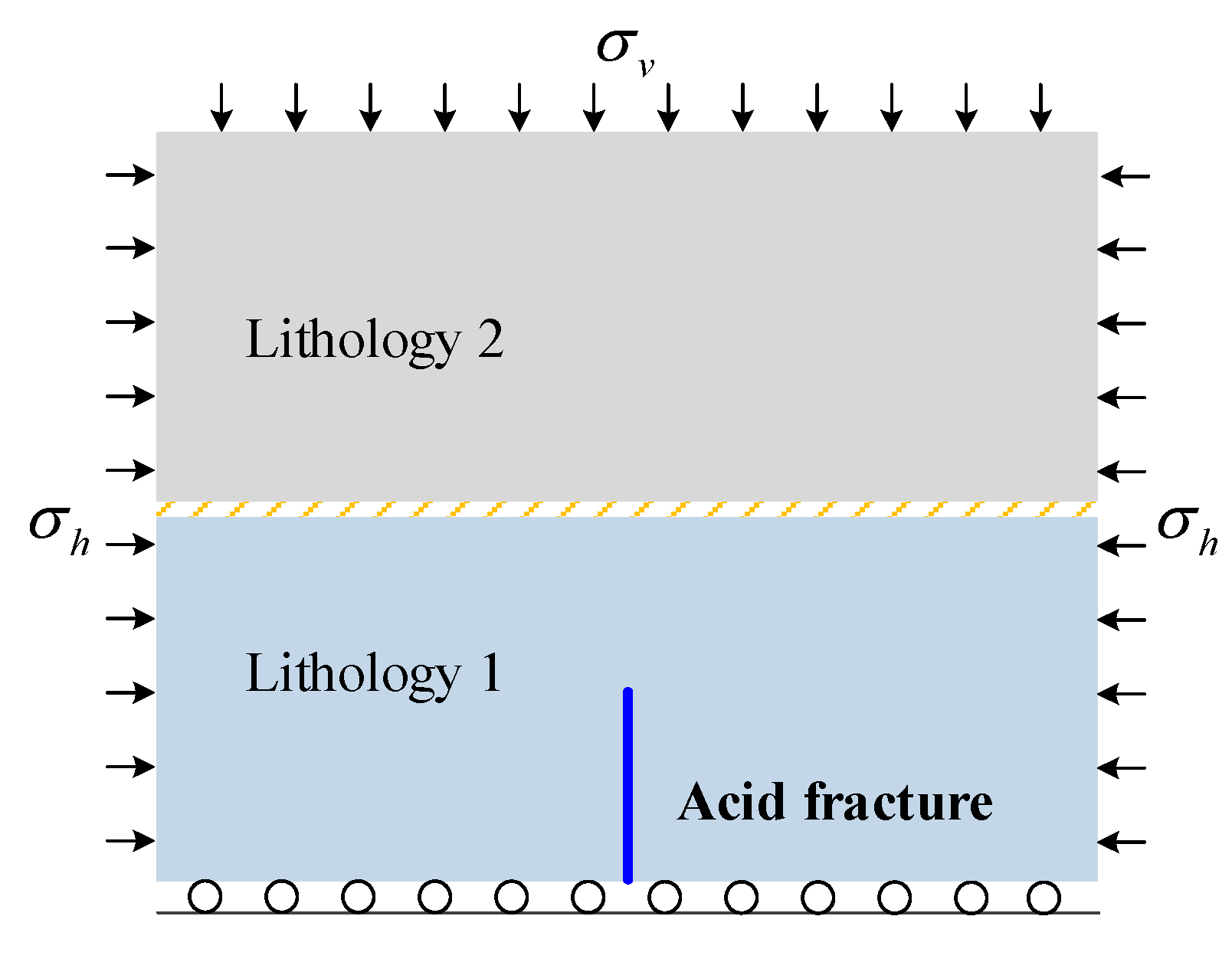
2. Model Description

This study explores the phenomenon of acid fracture propagation in a heterogeneous layered reservoir, with the conceptual model illustrated in Figure 1. The reservoir comprises two layers with distinct rock properties, separated by an interface that can be considered a weak plane. The reservoir exhibits heterogeneity and is in a saturated state. We have previously presented a hydro-mechano-reactive flow-coupled model [26], and the model is now extended to analyze acid fracture propagation in layered reservoirs. The fundamental equations are presented below.

2.1. Characterization of Rock Heterogeneity

Rock heterogeneity arises from micro constitutes and structure, influencing the macro mechanical properties. The rock has multi-scale constitutes and structures. At the microscopic scale, the solid matrix contains dispersed pores, creating a porous structure. At the mesoscopic scale, mineral inclusions are embedded within this porous framework, resulting in a composite material. We employ the Mori–Tanaka scheme to estimate the macroscopic mechanical parameters of the rock by two steps [27,28].
The initial step addresses the impact of micro-scale pores by estimating the porous medium’s effective elastic stiffness, expressed as follows [29]:
C m p = C m : ( I f p A p )
where Cm represents the solid matrix’s elastic stiffness, I refers to the unit tensor, fp is the volume ratio of pores to matrix, and Ap is the strain concentration tensor, calculated as follows:
A p = ( I P p : C m ) 1 : ( 1 f p ) I + f p ( I P p : C m ) 1 1
where Pp denotes the Hill tensor of the porous matrix, which is derived through the integration of the Green function [27,29].
The subsequent step deals with the impact of mineral inclusions, which are simplified into an equivalent phase:
C h o m = C m p + f i ( C i C m p ) : A i
where Ai connects the macroscopic strain to the local strain within inclusions:
A i = I + P i : ( C i C m p ) 1 : ( 1 f i ) I + f i I + P i : ( C i C m p ) 1 1
where Pi is the Hill tensor for the macroscopic medium.
This homogenization approach effectively captures the multi-scale heterogeneity of the rock, considering both micro-scale and mesoscopic influences.

2.2. Equations of Fluid Flow and Acid Transport

Regarding fluid flow and acid transport, Panga et al. [30] proposed the dual-scale continuum model consisting of the Darcy-scale mode and the pore-scale model. When fractures form and extend within a reservoir, the characteristics of the surrounding region, including permeability, compressibility, and Biot’s coefficient, change considerably. These evolving properties are recalculated using a linear interpolation approach developed by Lee et al. [31]. The continuity equation for fluid flow is given by the following:
ϕ t + S t p t + k t μ p = Q 0 α t ε v o l t
where kt, St, and αt represent the equivalent permeability, compressibility, and Biot’s coefficient of the medium, respectively, all derived through the interpolation approach [31]. ϕ is porosity, μ is the fluid viscosity and Q0 serves as the source term.
Acid transport within the reservoir includes processes such as convection, dispersion, and transfer. The continuity equation for acid transport is given by the following:
ϕ C f t + v C f = ϕ D e C f a v R C f
In this context, v represents fluid velocity, De is the effective dispersion tensor, Cf denotes acid concentrations in the fluid phase, and αv is the specific surface area. R(Cf) is the transfer term, which describes the movement of acid to the fluid–solid interface, and is modeled as a first-order kinetic reaction [30].
The transfer term induces changes in porosity:
ϕ t = R C f a v α d ρ s
where αd represents the dissolution coefficient, and ρs denotes the density of the rock.
At the pore scale, various empirical formulas are employed to update key parameters that influence fluid flow and chemical reactions. This study adopts the approach developed by Panga et al. [30], which has been successfully implemented in previous research [26]. This methodology provides a comprehensive framework for modeling the evolution of pore-scale properties during acid dissolution processes.

2.3. Equations of Mechanical Deformation and Crack Propagation

The total energy functional of a porous medium, accounting for elastic strain energy, crack surface energy, and fluid pressure dissipation energy, is defined as follows:
Ψ ( u , Γ , p ) = Ω ψ ( ε ) d Ω + Γ G c d Γ Ω α t p ( u ) d Ω Ω b u d Ω Ω t t ¯ u d Ω t
where u represents the displacement tensor, p denotes the fluid pressure, ψ is the elastic strain energy, Gc refers to the critical energy release rate, b stands for body force, and t ¯ corresponds to the traction.
Researchers have demonstrated that acid dissolution leads to a reduction in the rock’s modulus [32,33]. Experimental findings reveal an exponential decrease in the elastic modulus with increased porosity due to acid dissolution [34]. To model this effect, a chemical damage parameter is incorporated into the degradation function [10,11]. Consequently, the phase field formulation of total energy becomes the following [26]:
Ψ = Ω g ( d , d chem ) ψ + ( ε ) + ψ ( ε ) d Ω + Ω G c 2 l 0 d d + d 2 l 0 d Ω Ω α p ( u ) d Ω Ω b u d Ω Ω t t ¯ u d Ω t
where ψ+ and ψ− represent tensile and compressive elastic strain energies, respectively. d represents the phase field, and l0 defines the characteristic length parameter.
The degradation function, incorporating both phase field and chemical damage, takes the following form:
g ( d , d chem ) = ( 1 k 0 ) d chem ( 1 d ) 2 + k 0
where k0 is a minor positive constant introduced to maintain the conditioning of the stiffness matrix when d nears 1.
Using the variational method results in the derivation of the governing equations for phase field evolution and rock deformation:
( σ a p I ) + b = 0
2 l 0 ( 1 k 0 ) d chem 2 ψ + G c + 1 d l 0 2 ( d d ) = 2 l 0 ( 1 k 0 ) d chem 2 H G c
The latter equation incorporates the local history variable H , which tracks the peak tensile strain energy encountered throughout the loading process. For initial fractures, the method outlined by Borden et al. [35] is used by prescribing strain field history.

3. Numerical Methods

This work presents a hybrid computational strategy that combines the finite element method (FEM) for discretizing stress and phase fields with the finite volume method (FVM) to handle fluid pressure and acid concentration. To tackle the nonlinear nature of the governing equations, an iterative scheme is adopted, leveraging the fixed-stress split approach to accelerate the convergence of the stress–pressure interaction.
The FEM yields weak formulations for both the stress field and phase field equations through the application of the virtual work principle:
Ω ( σ α p I ) : ε ( δ u ) d Ω = Ω b δ u d Ω + Ω t t ¯ δ u d Ω t
Ω 2 ( 1 k 0 ) d chem 2 H + G c l 0 d δ d d Ω + Ω G c l 0 d ( δ d ) d Ω = 2 Ω ( 1 k 0 ) d chem 2 H δ d d Ω
where δu represents the virtual displacement tensor, while δd denotes the virtual variable associated with the phase field.
For fluid pressure, the FVM is applied by integrating the equation over elements, resulting in the following:
Ω e S t p t d V Ω e k t μ p d V = Ω e Q 0 R C s a v α d ρ s d V Ω e α t ε v o l t d V
Similarly, integrating the acid concentration equation gives the following:
Ω e ( ϕ C f ) t d V + Ω e ( v C f ) d V = Ω e ( ϕ D e C f ) d V Ω e k c k s a v k c + k s C f d V
The inter-element fluid flux is governed by the flow conductivity at interfaces, which is computed using harmonic averaging. For the acid concentration integration equation, an upwind method is utilized to compute the advection flux, while harmonic averaging is applied to determine the diffusion flux. Temporal derivatives are resolved using a backward differencing scheme.
Upon discretizing all field equations, an efficient iterative algorithm is deployed to solve them. Each timestep involves iterative updates of fluid pressure, displacement, and phase field variables until convergence criteria are met. Following this, the acid concentration is calculated based on the newly obtained fluid pressure field through a decoupled procedure. The material properties are then refreshed for the next computational step. For comprehensive implementation details, readers are referred to our earlier publication [26].

4. Simulation Results

The hydro-mechano-reactive flow coupled model was validated by simulating fracture propagation, acid transport, and crack growth after acidizing under conditions that were previously studied both experimentally and numerically. The validation process included comparisons of fracture geometry, reactive transport dynamics, and acid penetration patterns against experimental observations and benchmark numerical models. The results demonstrated good agreement within acceptable error margins, confirming the model’s capability to accurately replicate acid fracture propagation behavior. These validation results provide a strong foundation for the simulations described in this study. For the sake of brevity, the detailed validation process is not repeated in this manuscript but can be found in our previous work [26]. This model is used to simulate fracture propagation within heterogeneous layered reservoirs, focusing on analyzing the distinct propagation modes of acid fractures in these complex geological settings, using insights gained from hydraulic fracture propagation results. While previous studies have extensively examined the effects of mechanical parameters and stress conditions on fracture propagation, this investigation specifically explores how various parameters of acid fracturing treatments, such as acid concentration and injection rate, affect fracture propagation dynamics. This approach aims to enhance the understanding of acid fracture behavior and improve treatment design for maximizing production efficiency in carbonate reservoirs.

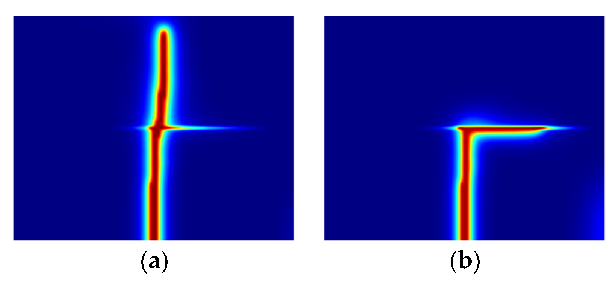
4.1. Hydraulic Fracturing in Layered Reservoirs

The study begins with a simulation of hydraulic fracture growth in a stratified reservoir, serving as a foundation for subsequent acid fracture analysis. The model comprises two layers with a weak interface and an initial fracture, as depicted in Figure 1. The heterogeneous nature of the reservoir is modeled through Weibull-distributed porosity and mineral inclusions, while the homogenization technique determines the bulk mechanical properties. The simulation parameters are summarized in Table 1, and Figure 2 displays the spatial variations in porosity and elastic modulus that characterize the reservoir’s heterogeneous structure. The elastic modulus of layer 1 was set to 25 GPa, layer 2 to 32 GPa, and the interface to 5 GPa, reflecting realistic variations commonly encountered in heterogeneous geological formations. These values were chosen to simulate contrasting mechanical responses of layered reservoirs and weaker interfaces, such as clay-rich zones or cemented bedding planes.
For simulating hydraulic fracture propagation, the acid transport process is omitted. The fracture propagation mode is depicted in Figure 3a. To explore alternative fracture modes, the vertical stress is reduced to 5 Mpa, resulting in fracture diversion into the interface, as shown in Figure 3b. These fracture propagation modes align with experimental results [11]. The evolution of injection pressure is illustrated in Figure 4, showing an initial rapid rise to a peak corresponding to fracture initiation, followed by a second peak as the fracture interacts with the interface, and finally stabilizing as the fracture propagates. These results demonstrate the model’s capability to accurately capture the key features of hydraulic fracturing behavior in layered reservoirs.

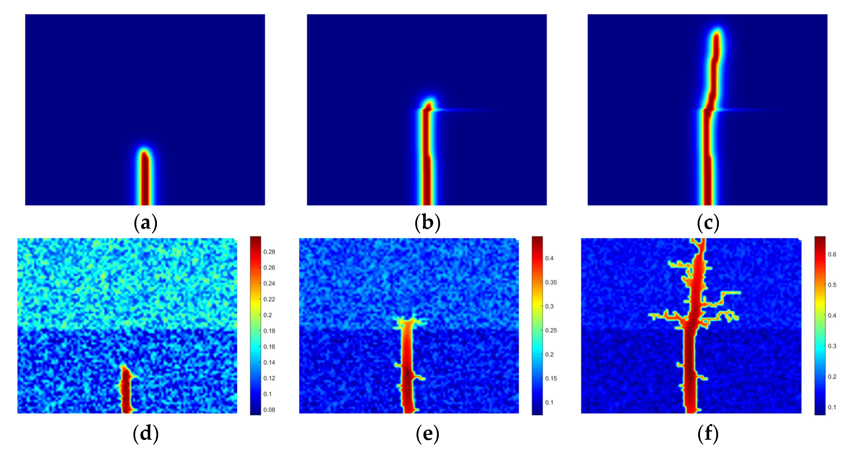
4.2. Propagation Modes of Acid Fracture in Layered Reservoir

To explore the propagation patterns of acid fractures within layered reservoirs, we employ a model with identical geometry, properties, and boundary conditions as in Section 4.1, but with acid transport considered. Table 1 lists the general parameters, and Table 2 outlines the additional parameters related to acid transport.
Under different conditions, various propagation modes are observed, as shown in Figure 5. For an injection rate of Q0 = 2.0 × 10⁻⁴ m2, the acid fracture initiates in layer 1, crosses the weak interface, and extends into layer 2 (Figure 5a). Adjusting parameters reveals additional modes: reducing the injection rate to 0.5 × 10⁻⁴ m2 results in fracture arrest at the interface (Figure 5b), while lowering the critical fracture energy of the interface to 1 Pa·m causes fracture diversion into the interface (Figure 5c). These modes can be explained by the pressure evolution and acid dissolution dynamics during the fracturing process.
The evolution of injection pressure for different fracture modes is compared in Figure 6. The overall behavior of acid fracturing resembles that of hydraulic fracturing. For crossing and diversion modes, injection pressure evolves similarly during fracture initiation due to identical injection rates. High pressure accumulates as the fracture reaches the interface, with the mode changing from crossing to diversion as the interface’s critical energy release rate decreases. For arresting mode, the pressure peaks at fracture initiation but fails to accumulate sufficiently for crossing or diverting, resulting in fracture arrest.
To gain deeper insights into the dynamics of phase field and porosity during the injection process, we analyze several critical time points: two peak pressure points and the final stable point, as depicted in Figure 6. For the crossing mode scenario, Figure 7 depicts the distributions of phase field and porosity at these key moments. Initially, minimal wormhole formation is observed around the fracture, even as it approaches the interface. This limited wormhole development allows the injected fluid to predominantly remain within the fracture, facilitating pressure buildup critical for efficient fracture development. Upon crossing the interface and advancing into layer 2, a significant increase in wormhole formation is noted around the fracture, indicating enhanced fluid interaction with the surrounding matrix. This behavior underscores the critical role of pressure dynamics and fluid distribution in fracture propagation efficiency.
In the diversion mode, the distributions of the phase field and porosity at various time points are illustrated in Figure 8. Initially, the porosity distribution resembles that observed in the crossing mode when the fracture approaches the interface, allowing for the accumulation of high pressure. However, the phase field exhibits distinct behavior as the fracture begins to divert into the interface. This diversion is attributed to the lower critical fracture energy characteristic of the interface. Consequently, more wormholes are formed along the direction of fracture diversion, highlighting the influence of interface parameters on fracture trajectory and fluid migration patterns.
In the arresting mode, the distributions of the phase field and porosity at various time points are depicted in Figure 9. Upon reaching the interface, two branches of wormholes develop at the fracture tip. Despite the rise in fluid pressure inside the fracture, it fails to achieve the critical threshold required to sustain further propagation. The introduction of acid promotes the formation and extension of wormholes, which evolve into primary pathways for fluid migration. As a result, the pressure within the fracture diminishes, effectively ceasing its advancement at the boundary interface.
Figure 10 and Figure 11 illustrate the distributions of fluid pressure and horizontal displacement for various fracture propagation modes. In the crossing and diversion modes, high fluid pressure is concentrated in and around the fracture. In contrast, the arresting mode exhibits pressure dissipation over a broader area, indicating a less focused pressure gradient. Moreover, the mode of fracture propagation significantly influences the displacement distribution, highlighting the interplay between pressure dynamics and mechanical responses in these geological settings.

4.3. Effect of Acid Concentration

The influence of acid concentration on fracture propagation is examined by adjusting Cf from 0 to 0.1 and 0.15. With Cf = 0, the scenario corresponds to hydraulic fracturing. The difference in stress between the vertical and minimum principal stresses plays a critical role in determining how fractures propagate. When Δσ = 1 MPa, the mode of propagation transitions from diversion to crossing and arresting with greater acid concentrations (Figure 12). Moderate acid concentration reduces peak pressure for fracture initiation, allowing high-pressure accumulation for crossing the interface. However, further increases in acid concentration form more wormholes, preventing pressure accumulation and resulting in the arresting mode (Figure 13).
As the stress difference rises to 2 MPa, the fracture propagation modes differ from those at Δσ = 1 MPa (Figure 14). In hydraulic fracturing, fractures cross the interface under higher stress differences. The propagation modes of acid fractures remain consistent with those at Δσ = 1 MPa, and the injection pressure evolution is similar (Figure 15). This indicates that while mechanical stress conditions influence hydraulic fractures significantly, the propagation modes of acid fractures are more sensitive to acid concentration and wormhole development.

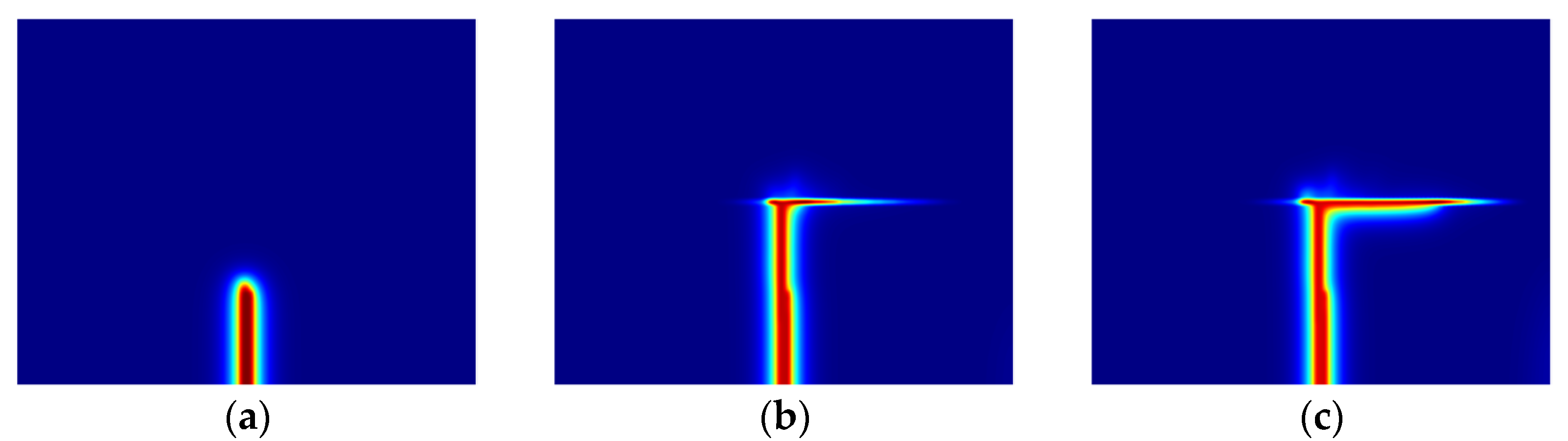
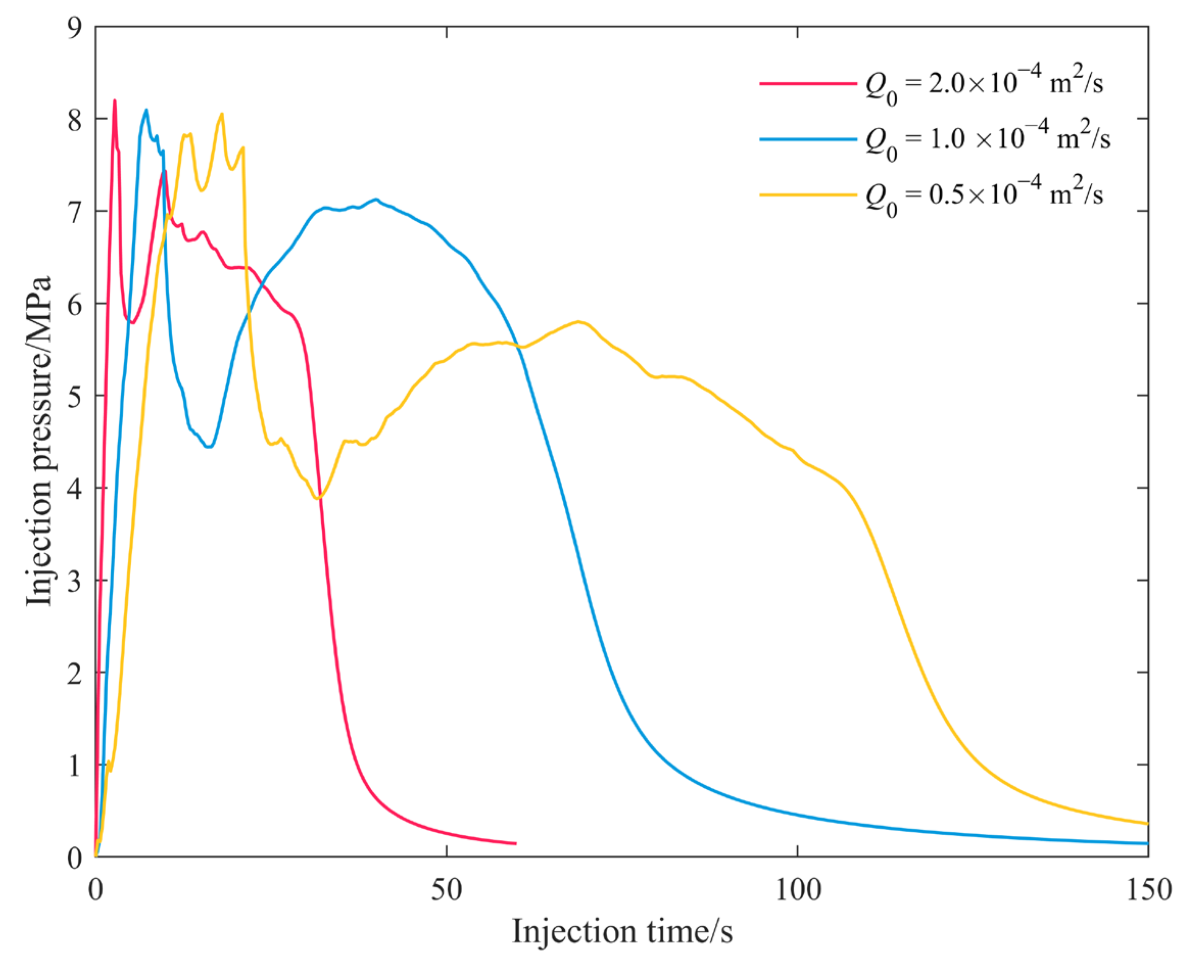
4.4. Effect of Injection Rate

Finally, the effect of the injection rate is analyzed. As the injection rate decreases, the acid fracture mode transitions from crossing to arresting, with an intermediate mode where the fracture crosses the interface but does not extend far into layer 2 (Figure 16). The porosity distributions and injection pressure for different modes are shown in Figure 17 and Figure 18. For a moderate injection rate, numerous wormhole branches form, allowing fluid pressure to rise to a second peak sufficient for crossing the interface. However, the high-pressure fluid dissipates along the wormholes, halting further fracture extension. These results suggest that optimizing the injection rate is crucial for controlling fracture propagation and maximizing the effectiveness of acid fracturing treatments.

5. Conclusions

This study presents a comprehensive investigation of acid fracture propagation behavior in heterogeneous layered reservoirs. The research reveals the complex interactions between treatment parameters and geological conditions, and the specific conclusions are as follows:
(1)
Three distinct propagation modes of acid fractures are identified: crossing, diversion, and arresting, each influenced by treatment parameters and geological conditions.
(2)
Increasing acid concentration initially facilitates fracture crossing by reducing peak pressure for initiation. However, excessive wormhole formation at higher concentrations leads to fracture arresting, underscoring the need for balanced acid concentration to optimize propagation.
(3)
The injection rate significantly affects fracture propagation, with moderate rates promoting optimal crossing by balancing pressure accumulation and dissipation. This highlights the importance of optimizing injection rates to control fracture behavior effectively.
(4)
Stress conditions and interface properties critically influence fracture propagation, with mechanical stress differences affecting hydraulic fractures more than acid fractures.

Author Contributions

Conceptualization, Q.Z. and T.Z.; methodology, Q.Z.; validation, S.L. and X.L.; formal analysis, T.L.; investigation, S.L. and L.B.; writing—original draft preparation, Q.Z.; writing—review and editing, X.L.; funding acquisition, Q.Z. and J.Y. All authors have read and agreed to the published version of the manuscript.

Funding

This research is funded by National Natural Science Foundation of China (52274038, 52034010, 52204226), and Open Fund of State Energy Center for Shale Oil Research and Development (ZC0613-0371).

Data Availability Statement

The data presented in this study are available on request from the corresponding author.

Conflicts of Interest

The authors declare no conflicts of interest.

References

  1. Wang, Y.; Hou, B.; Wang, D.; Jia, Z. Features of Fracture Height Propagation in Cross-Layer Fracturing of Shale Oil Reservoirs. Pet. Explor. Dev. 2021, 48, 469–479. [Google Scholar] [CrossRef]
  2. Zeng, Q.; Bo, L.; Li, Q.; Sun, J.; Yao, J. Numerical Investigation of Hydraulic Fracture Propagation Interacting with Bedding Planes. Eng. Fract. Mech. 2023, 291, 109575. [Google Scholar] [CrossRef]
  3. Zheng, H.; Pu, C.; Sun, C. Numerical Investigation on the Hydraulic Fracture Propagation Based on Combined Finite-Discrete Element Method. J. Struct. Geol. 2020, 130, 103926. [Google Scholar] [CrossRef]
  4. Yang, X.; Chang, C.; Cheng, Q.; Xie, W.; Hu, H.; Li, Y.; Huang, Y.; Peng, Y. The Influence of Rock and Natural Weak Plane Properties on the Vertical Propagation of Hydraulic Fractures. Processes 2024, 12, 2477. [Google Scholar] [CrossRef]
  5. Zhang, B.; Guo, T.; Chen, M.; Wang, J.; Cao, J.; Wang, H.; Qu, Z. Effect of Bedding Planes and Property Contrast between Layers on the Propagation Mechanism of Hydraulic Fracture Height in Shale Reservoirs. Comput. Geotech. 2024, 175, 106715. [Google Scholar] [CrossRef]
  6. Guo, J.; Luo, B.; Lu, C.; Lai, J.; Ren, J. Numerical Investigation of Hydraulic Fracture Propagation in a Layered Reservoir Using the Cohesive Zone Method. Eng. Fract. Mech. 2017, 186, 195–207. [Google Scholar] [CrossRef]
  7. Yang, L.; Sheng, X.; Zhang, B.; Yu, H.; Wang, X.; Wang, P.; Mei, J. Propagation Behavior of Hydraulic Fractures in Shale under Triaxial Compression Considering the Influence of Sandstone Layers. Gas Sci. Eng. 2023, 110, 204895. [Google Scholar] [CrossRef]
  8. Tan, P.; Chen, Z.-W.; Huang, L.-K.; Zhao, Q.; Shao, S.-R. Evaluation of the Combined Influence of Geological Layer Property and In-Situ Stresses on Fracture Height Growth for Layered Formations. Pet. Sci. 2024, 21, 3222–3236. [Google Scholar] [CrossRef]
  9. Liu, Y.; Tang, D.; Xu, H.; Zhao, T.; Hou, W. Effect of Interlayer Mechanical Properties on Initiation and Propagation of Hydraulic Fracturing in Laminated Coal Reservoirs. J. Pet. Sci. Eng. 2022, 208, 109381. [Google Scholar] [CrossRef]
  10. Wang, F.; Liu, W.; Deng, J.; Xu, K.; Xing, C.; Yan, K. Hydraulic Fracture Propagation Research in Layered Rocks Based on 3D FEM Modeling and Laboratory Experiments. Geoenergy Sci. Eng. 2024, 234, 212670. [Google Scholar] [CrossRef]
  11. He, J.-C.; Zhang, K.-S.; Liu, H.-B.; Tang, M.-R.; Zheng, X.-L.; Zhang, G.-Q. Laboratory Investigation on Hydraulic Fracture Propagation in Sandstone-Mudstone-Shale Layers. Pet. Sci. 2022, 19, 1664–1673. [Google Scholar] [CrossRef]
  12. Huang, C.-H.; Zhu, H.-Y.; Wang, J.-D.; Han, J.; Zhou, G.-Q.; Tang, X.-H. A FEM-DFN Model for the Interaction and Propagation of Multi-Cluster Fractures during Variable Fluid-Viscosity Injection in Layered Shale Oil Reservoir. Pet. Sci. 2022, 19, 2796–2809. [Google Scholar] [CrossRef]
  13. Lyu, J.; Hou, B.; Zhou, T. Fracture Propagation Behavior via Multi-Cluster Fracturing in Sandstone-Shale Interbedded Reservoirs. Geoenergy Sci. Eng. 2024, 243, 213356. [Google Scholar] [CrossRef]
  14. Zeng, Q.; Yao, J.; Shao, J. An Extended Finite Element Solution for Hydraulic Fracturing with Thermo-Hydro-Elastic–Plastic Coupling. Comput. Methods Appl. Mech. Eng. 2020, 364, 112967. [Google Scholar] [CrossRef]
  15. Zeng, Q.; Bo, L.; Liu, W.; Huang, Z.; Yao, J. An Investigation of Hydraulic Fracture Propagation in Multi-Layered Formation via the Phase Field Method. Comput. Geotech. 2023, 156, 105258. [Google Scholar] [CrossRef]
  16. Yi, L.-P.; Li, X.-G.; Yang, Z.-Z.; Yang, C.-X. Phase Field Modeling of Hydraulic Fracturing in Porous Media Formation with Natural Fracture. Eng. Fract. Mech. 2020, 236, 107206. [Google Scholar] [CrossRef]
  17. Qin, M.; Yang, D.; Jia, Y.; Zhou, Y. Peridynamics Modeling of Hydraulic Fracture Interaction with Natural Fractures in Fractured Rock Mass. Eng. Fract. Mech. 2024, 307, 110299. [Google Scholar] [CrossRef]
  18. Mao, S.; Wu, K.; Moridis, G. Integrated Simulation of Three-Dimensional Hydraulic Fracture Propagation and Lagrangian Proppant Transport in Multilayered Reservoirs. Comput. Methods Appl. Mech. Eng. 2023, 410, 116037. [Google Scholar] [CrossRef]
  19. Aimene, Y.; Hammerquist, C.; Ouenes, A. Anisotropic Damage Mechanics for Asymmetric Hydraulic Fracture Height Propagation in a Layered Unconventional Gas Reservoir. J. Nat. Gas Sci. Eng. 2019, 67, 1–13. [Google Scholar] [CrossRef]
  20. Li, H.; Kang, T.; Zhang, R.; Zhang, X.; Liang, X.; Zhu, W.; Zhang, B. Numerical Study of the Effects of Loading Parameters on High-Energy Gas Fracture Propagation in Layered Rocks with Peridynamics. Eng. Fract. Mech. 2024, 310, 110516. [Google Scholar] [CrossRef]
  21. Ni, T.; Fan, X.; Zhang, J.; Zaccariotto, M.; Galvanetto, U.; Schrefler, B. A Peridynamic-Enhanced Finite Element Method for Thermo–Hydro–Mechanical Coupled Problems in Saturated Porous Media Involving Cracks. Comput. Methods Appl. Mech. Eng. 2023, 417, 116376. [Google Scholar] [CrossRef]
  22. Xu, H.; Cheng, J.; Zhao, Z.; Lin, T.; Liu, G.; Chen, S. Coupled Thermo-Hydro-Mechanical-Chemical Modeling on Acid Fracturing in Carbonatite Geothermal Reservoirs Containing a Heterogeneous Fracture. Renew. Energy 2021, 172, 145–157. [Google Scholar] [CrossRef]
  23. Kong, X.; Shi, X.; Xie, G. Numerical Characterization of Acid Fracture Wall Etching Morphology and Experimental Investigation on Sensitivity Factors in Carbonate Reservoirs. Geoenergy Sci. Eng. 2024, 237, 212762. [Google Scholar] [CrossRef]
  24. Gou, B.; Zhang, J.; Wang, K.; Xu, K.; Xiao, B.; Zeng, J.; Guo, J. Effect of Acid Viscosity on Conductivity during Online Acid-Fracturing in Ultra-Deep Carbonate Reservoir. Geoenergy Sci. Eng. 2024, 243, 213381. [Google Scholar] [CrossRef]
  25. Zhu, T.; Wei, X.; Zhang, Z. Numerical Simulation of Hydraulic-Mechanical-Chemical Field Coupled Acid Fracturing in Complex Carbonate Reservoir. Comput. Geotech. 2023, 156, 105277. [Google Scholar] [CrossRef]
  26. Zeng, Q.; Li, T.; Liu, P.; Bo, L.; Yao, C.; Yao, J. A Phase Field Framework to Model Acid Fracture Propagation with Hydro-Mechano-Reactive Flow Coupling. Comput. Geotech. 2024, 174, 106658. [Google Scholar] [CrossRef]
  27. Zhao, J.J.; Shen, W.Q.; Shao, J.F.; Liu, Z.B.; Vu, M.N. A Constitutive Model for Anisotropic Clay-Rich Rocks Considering Micro-Structural Composition. Int. J. Rock Mech. Min. Sci. 2022, 151, 105029. [Google Scholar] [CrossRef]
  28. Yu, Z.; Shao, J.; Sun, Y.; Wang, M.; Vu, M.; Plua, C. Numerical Analysis of Hydro-Thermal Fracturing in Saturated Rocks by Considering Material Anisotropy and Micro-Structural Heterogeneity. Int. J. Rock Mech. Min. Sci. 2023, 170, 105457. [Google Scholar] [CrossRef]
  29. Giraud, A.; Huynh, Q.V.; Hoxha, D.; Kondo, D. Application of Results on Eshelby Tensor to the Determination of Effective Poroelastic Properties of Anisotropic Rocks-like Composites. Int. J. Solids Struct. 2007, 44, 3756–3772. [Google Scholar] [CrossRef]
  30. Panga, M.K.R.; Ziauddin, M.; Balakotaiah, V. Two-Scale Continuum Model for Simulation of Wormholes in Carbonate Acidization. AIChE J. 2005, 51, 3231–3248. [Google Scholar] [CrossRef]
  31. Lee, S.; Wheeler, M.F.; Wick, T. Pressure and Fluid-Driven Fracture Propagation in Porous Media Using an Adaptive Finite Element Phase Field Model. Comput. Methods Appl. Mech. Eng. 2016, 305, 111–132. [Google Scholar] [CrossRef]
  32. Palchik, V.; Hatzor, Y.H. Crack Damage Stress as a Composite Function of Porosity and Elastic Matrix Stiffness in Dolomites and Limestones. Eng. Geol. 2002, 63, 233–245. [Google Scholar] [CrossRef]
  33. Croizé, D.; Bjørlykke, K.; Jahren, J.; Renard, F. Experimental Mechanical and Chemical Compaction of Carbonate Sand. J. Geophys. Res. 2010, 115, B11204. [Google Scholar] [CrossRef]
  34. Wojtacki, K.; Lewandowska, J.; Gouze, P.; Lipkowski, A. Numerical Computations of Rock Dissolution and Geomechanical Effects for CO2 Geological Storage. Int. J. Numer. Anal. Methods Geomech. 2015, 39, 482–506. [Google Scholar] [CrossRef]
  35. Borden, M.J.; Verhoosel, C.V.; Scott, M.A.; Hughes, T.J.R.; Landis, C.M. A Phase-Field Description of Dynamic Brittle Fracture. Comput. Methods Appl. Mech. Eng. 2012, 217–220, 77–95. [Google Scholar] [CrossRef]
Figure 1. Schematic representation of acid fracturing in heterogeneous layered reservoir.
Water 16 03586 g001
Figure 2. Distribution of reservoir parameters: (a) porosity; (b) elastic modulus (GPa).
Water 16 03586 g002
Figure 3. Hydraulic fracture propagation modes: (a) crossing mode; (b) diversion mode.
Water 16 03586 g003
Figure 4. Evolution of injection pressure for different fracture modes.
Water 16 03586 g004
Figure 5. Propagation modes of acid fracture in various conditions: (a) crossing mode, injection rate Q0 = 2.0 × 10⁻⁴ m2; (b) arresting mode, injection rate Q0 = 0.5 × 10⁻⁴ m2; (c) diversion mode, injection rate Q0 = 2.0 × 10⁻⁴ m2 and Gcf = 1 Pa·m.
Water 16 03586 g005
Figure 6. Evolution of injection pressure for different fracture modes.
Water 16 03586 g006
Figure 7. Distributions of phase field and porosity for crossing mode at different times: (a) phase field, at point A; (b) phase field, at point B; (c) phase field, at point C; (d) porosity, at point A; (e) porosity, at point B; (f) porosity, at point C.
Water 16 03586 g007
Figure 8. Distributions of phase field and porosity for diversion mode at different times: (a) phase field, at point H; (b) phase field, at point I; (c) phase field, at point J; (d) porosity, at point H; (e) porosity, at point I; (f) porosity, at point J.
Water 16 03586 g008aWater 16 03586 g008b
Figure 9. Distributions of phase field and porosity for diversion mode at different times: (a) phase field, at point D; (b) phase field, at point E; (c) phase field, at point F; (d) porosity, at point D; (e) porosity, at point E; (f) porosity, at point F.
Water 16 03586 g009
Figure 10. Pressure profiles for various modes: (a) crossing mode; (b) diversion mode; (c) arresting mode.
Water 16 03586 g010
Figure 11. Distributions of horizontal displacement for various modes: (a) crossing mode; (b) diversion mode; (c) arresting mode.
Water 16 03586 g011
Figure 12. Fracture behavior modes at varying acid concentrations with Δσ = 1 MPa: (a) diversion mode, Cf = 0; (b) crossing mode, Cf = 0.1; (c) arresting mode, Cf = 0.15.
Water 16 03586 g012
Figure 13. Variation in injection pressure at varying acid concentrations with Δσ = 1 MPa.
Water 16 03586 g013
Figure 14. Fracture behavior modes at varying acid concentrations with Δσ = 2 MPa: (a) diversion mode, Cf = 0; (b) crossing mode, Cf = 0.1; (c) arresting mode, Cf = 0.15.
Water 16 03586 g014
Figure 15. Variation in injection pressure at varying acid concentrations with Δσ = 2 MPa.
Water 16 03586 g015
Figure 16. Fracture propagation modes at varying injection rates: (a) crossing mode, Q0 = 2.0 × 10⁻⁴ m2/s; (b) intermediate mode, Q0 = 1.0 × 10⁻⁴ m2/s; (c) arresting mode, Q0 = 0.5 × 10⁻⁴ m2/s.
Water 16 03586 g016
Figure 17. Porosity distribution at varying injection rates: (a) Q0 = 2.0 × 10⁻⁴ m2/s; (b) Q0 = 1.0 × 10⁻⁴ m2/s; (c) Q0 = 0.5 × 10⁻⁴ m2/s.
Water 16 03586 g017
Figure 18. Evolution of injection pressure for different injection rates.
Water 16 03586 g018
Table 1. Parameters used for simulating hydraulic fracture growth in layered reservoir.
ParameterNotationMagnitudeUnit
Domain lengthL0.5m
Domain heightH0.4m
Height of layer 1L10.195m
Height of layer 2L20.195m
Height of interfaceL120.01m
Length of initial hydraulic fracturelhf0.1m
Characteristic length parameterl00.01
Mean porosity of layer 1fp10.12
Mean porosity of layer 2fp20.15
Elastic modulus of solid matrix in layer 1Em125GPa
Elastic modulus of solid matrix in layer 2Em232GPa
Elastic modulus of interfaceEmf5GPa
Elastic modulus of mineral inclusionEi98GPa
Volume ratio of mineral inclusionfi0.4
Critical fracture energy of layer 1Gc150Pa·m
Critical fracture energy of layer 2Gc2120Pa·m
Critical fracture energy of interfaceGcf2Pa·m
Primary vertical stressσv7MPa
Minimum horizontal stressσh5MPa
Matrix permeabilitykr1.0 × 10−15m2
Fracture permeabilitykr1.0 × 10−8m2
Injection rateQ02.0 × 10−4m2/s
Fluid viscosityμ1.0 × 10⁻³Pa·s
Table 2. Additional parameters used for simulating acid fracture propagation in layered reservoir.
ParameterNotationMagnitudeUnit
Acid concentrationCf00.15
Injection rateQ02.0 × 10−4m2/s
Acid reaction rateks2.0 × 10−3m/s
Molecular diffusion coefficientDm3.6 × 10−9m2/s
Asymptotic Sherwood numberSh3.66
Constantsαos, λX, λT0.5
Initial average permeabilitykr1.0 × 10−15m2
Specific surface areaα05.0 × 10³m−1
Pore diameterd01.0 × 10−5m
Pore broadening parameterβ1
Chemical degradation coefficientr5
Rock densityρs2.71 × 103kg/m3
Disclaimer/Publisher’s Note: The statements, opinions and data contained in all publications are solely those of the individual author(s) and contributor(s) and not of MDPI and/or the editor(s). MDPI and/or the editor(s) disclaim responsibility for any injury to people or property resulting from any ideas, methods, instructions or products referred to in the content.

