Article

The Degradation of Rhodamine B by an Electro-Fenton Reactor Constructed with Gas Diffusion Electrode and Heterogeneous CuFeO@C Particles

1
College of Environment and Safety Engineering, Qingdao University of Science and Technology, Qingdao 266042, China
2
Department of Environmental Design, Qingdao University of Science and Technology, Qingdao 266042, China
*
Authors to whom correspondence should be addressed.
Water 2024, 16(20), 2906; https://doi.org/10.3390/w16202906
Submission received: 12 September 2024 / Revised: 30 September 2024 / Accepted: 2 October 2024 / Published: 13 October 2024
(This article belongs to the Special Issue Advanced Technologies for Wastewater Treatment and Water Reuse)

Abstract

:
Compared with conventional Fenton processes, the electro-Fenton process consumes fewer chemicals and produces less sludge, as it can generate the required Fenton’s reagents in situ. In this work, an electro-Fenton reactor was constructed to treat synthetic rhodamine B (Rh B) wastewater, in which a gas diffusion electrode (GDE) was used as a cathode to produce H2O2, and heterogeneous CuFeO@C particles were used to generate Fe2+ in situ. The results indicated that the gas diffusion electrode made of elements N-S-B and r-graphene oxide (NSB-r-GO) composites produced more H2O2 than the one made from r-graphene oxide (r-GO), under the conditions of 0.1 mol ·L−1 Na2SO4 electrolyte, 10 mA·cm−2 current density, and 1.0 L·min−1 O2 flow rate, with the accumulated H2O2 production reaching 105.43 mg·L−1. Additionally, different iron morphologies, including octahedral Fe (II), octahedral Fe (III), and tetrahedral Fe (III), were found in the calcined CuFeO@C particles, approximately 1.0 mg·L−1 of iron ions dissolved in the electrolyte was detected, which worked simultaneously as conductive electrodes in a conceptual three-dimensional electrochemical reactor consisting of a gas diffusion electrode cathode, Ti/RuSn anode, and CuFeO@C particle electrodes. No external Fenton reagents were necessary.

1. Introduction

Dye wastewater, containing complex chemical components, is commonly toxic, carcinogenic, and non-biodegradable, and about one million tons of dye wastewater per year are discharged into the water bodies, which poses safety risks to the aquatic environment and human health [1].
This issue can be addressed using many methods, including adsorption, membrane separation, coagulation, biodegradation, etc. For example, adsorption, as a separation process, is highly efficient in adsorbing dye pollutants onto porous adsorbents, which include activated carbon, alumina, ion exchange resin, metal–organic frameworks, zeolite, etc. However, dye pollutants are merely absorbed on the absorbents and not degraded completely, which produce hazardous waste and still require subsequent treatment. Membranes can effectively capture dye molecules from wastewater, but it has the drawbacks of membrane fouling. Coagulation can precipitate dye molecules dispersed in water, but it consumes large amounts of external coagulants and produces excess chemical sludge. As a prevail wastewater treatment method, the activated sludge process has been used to treat all kinds of industrial wastewater, including dye wastewater from microorganisms’ metabolic and digestive processes; however, their effectiveness may be negatively affected by the low biodegradability of dye wastewater.
Although dye wastewater can be effectively treated using many methods, some of them have obvious shortcomings, such as inevitable secondary pollutants, generated hazardous waste, and high operational costs [2,3,4,5].
Advanced oxidation processes (AOPs) are generally considered strong oxidation methods, which generate strong oxidizing free radicals (such as ·OH) as oxidants to decompose dye wastewater rapidly. It commonly includes Fenton and Fenton-like reactions, photocatalytic oxidation, ozone oxidation, electrochemical reactions, etc. For example, iron-doped SBA-15 mesoporous silica, prepared by the wet impregnation method, is used as a kind of heterogeneous catalyst in the electro-Fenton process to treat Rh B dye wastewater, achieving a decolorization rate of 97.7% and a TOC removal rate of 35.2% of Rh B (10 mg·L−1) [6].
Although dye wastewater can be effectively decomposed by conventional Fenton processes, plenty of chemical reagents such as H2O2 and Fe2+ ions are required, which results in the generation of chemical sludge as hazardous waste and limited application in wastewater treatment. However, the electro-Fenton processes can achieve a free addition of chemical reagent, which generates H2O2 in situ on the surfaces of gas diffusion electrodes (GDEs) through the reactions shown in Equation (1) [7,8,9] and reduces the consumption of the chemical reagent H2O2; the advantages mentioned above make this process a promising approach for the effective decomposition of many types of pollutants.
O 2 + 2 H 2 O + 2 e 2 H 2 O 2   ( E 0 = 0.695   V )
F e ( II ) + H 2 O 2 F e ( III ) + · OH + O H
F e ( III ) + H 2 O 2 F e ( II ) + HOO · + H +
F e ( III ) + HOO · F e ( II ) + O 2 + H +
Thus, the structure and characteristics of GDE are very crucial for the generation of H2O2 in situ; these GDE cathodes are commonly made of carbon-based materials, which include activated carbon fiber, carbon nanotubes, graphene oxide and biochar. Their conductivities and porous structures can be modified by incorporating polymer matrices and doping with transition metal or non-metallic elements (such as N, O, F, P, and B) [10,11,12,13,14]. Thus, oxygen from aeration can dissolve and diffuse into the GDE and then be reduced into H2O2, a key Fenton reagent.
As another Fenton reagent and catalyst, Fe2+ can also be supplied by the reduction of Fe3+ on the surface of a cathode [15]. Fe3+ could be released from many kinds of heterogeneous catalysts containing iron components, such as zero-valence iron, ferric oxide, various natural iron ores, and Prussian blue derivatives. For example, a Prussian blue derivative (Mg, Cu, Ni) (Fe, Al)2O4 was used as a heterogeneous catalyst for Fenton reagents to decompose Rh B wastewater with a degradation rate of Rh B close to 100%, while the consumption of Prussian blue derivatives was almost negligible. The transformation of Fe (II) to Fe (III) is shown in Equations (2)–(4) [16,17].
Thus, during some electro-Fenton processes, H2O2 can be generated by the surface-modified GDE cathode, and Fe2+ can also be produced at the cathode, but it is very difficult to generate H2O2 and Fe2+ efficiently and simultaneously within the same electrode or reactor.
In this work, an electro-Fenton reactor was constructed for the degradation of synthetic Rh B wastewater, the modified GDE cathode was used to produce H2O2 in situ, and the CuFeO@C catalyst particles, obtained from a Prussian blue derivative, were used to supply Fe2+ in situ. The objectives of this work were as follows: (1) to evaluate the H2O2 production performance of prepared GDEs; (2) to characterize the heterogeneous CuFeO@C particles as a Fenton reagent; and (3) to assess the removal efficiency of Rh B through the electro-Fenton process.

2. Materials and Methods

2.1. Chemical Reagents

All the main chemicals, including Rh B, urea, thiourea, boric acid, anhydrous ethanol, the polytetrafluoroethylene (PTFE) solution, and sulfuric acid, were purchased from China National Pharmaceutical Group Chemical Reagent Co., Ltd. (Shanghai, China). Graphene oxide (GO) was purchased from Shanghai Yuanye Biotechnology Co., Ltd., (Shanghai, China), and foam nickel was supplied by Qingdao Keke Trade Co., Ltd. (Qingdao, China).

2.2. Preparation Processes of Modified r-GO Composites and GDEs

The nickel foam was designated as the supporting material of GDE, on which surfaces elements N-S-B and r-GO compounds were pasted. Its pretreatment process was as follows: The nickel foam was cut into rectangular plates with a length of 5 cm and a width of 2.5 cm, continuously cleaned via a deoiling and deoxidizing process, placed ultrasonically in anhydrous ethanol for 30 min, and then cleaned with deionized water and placed sequentially in 0.5 mol·L−1 diluted hydrochloric acid for ultrasonic process for 15 min. Then, it was washed with deionized water until neutral and immersed ultrasonically in deionized water for 15 min. Finally, it was dried and sealed at 80 °C for the subsequent preparation of GDE.
All surface-modified materials such as the r-GO and NSB-r-GO composite were made from graphene oxide (GO) and chemical reagents containing elements N-S-B.
The preparation process of the r- graphene oxide composite was as follows: firstly, 0.048 mol of graphene oxide was added into 80 mL distilled water, ultrasonically dissolved and dispersed for 30 min, transferred to a polytetrafluoroethylene high-temperature reactor for a reaction at 180 °C for 12 h, and then cooled to room temperature, removed and centrifuged with deionized water and anhydrous ethanol before it was freeze-dried for 12 h and finally sealed for usage.
The preparation process of the NSB-r-GO composite was almost the same as that of the r-GO composite mentioned above, but the key difference between them was as follows: for the NSB-r-GO composite, certain amounts of urea, thiourea, and boric acid were added at a ratio of 5:3:2 into the 80 mL distilled water along with the addition of 0.048 mol of graphene oxide.
The preparation process of GDE was as follows: firstly, 5 mL ethanol and 0.2 g modified GO was added into a beaker; then, the latter was ultrasonically dispersed for 30 min, added with a certain amount of PTFE solution as binder, and continued to be ultrasonically treated for 30 min. The mixture was concentrated into a wet paste at 70 °C and then uniformly coated on one side of the pretreated nickel foam mesh, which was used as the catalytic layer of the gas diffusion electrode (GDE). However, the diffusion layer was coated on the other side of the nickel foam mesh, which had a preparation process that was the same as that of the catalytic layer, except that 0.2 g of modified GO was replaced by Carbon Black. Finally, the coated nickel foam mesh was treated in the cold for 3 min at a pressure of 10 MPa. Then, the pressed nickel foam mesh was placed in a tubular furnace, heated to 350 °C at a rate of 5 °C·min−1, and calcined at a constant temperature for 60 min. The calcined electrode was immersed in anhydrous ethanol to remove surficial organic matters, then cleaned with deionized water, and finally dried at 80 °C to obtain a sample of gas diffusion electrode (GDE) [18,19,20].

2.3. Preparation Process of CuFeO@C Particles

The CuFeO@C particles electrodes was manufactured as follows: 2 g polyvinylpyrrolidone K-30 (PVP) was dissolved in 100 mL deionized water; then, 2 mmol·L−1 CuCl2·2H2O was dispersed ultrasonically in it; next, 2 mmol·L−1 K3[Fe(CN)]6 was added drop by drop and stirred for 30 min, maintaining static aging for 24 h. The product was centrifugally washed with deionized water and anhydrous ethanol and dried at 60 °C for 12 h to obtain Cu-Fe Prussian Blue particles (Cu3[Fe(CN)6]2), which was heated to 500 °C at a temperature gradient of 5 °C·min−1 and calcined in air for 2 h at the same temperature to obtain the heterogeneous catalyst CuFeO@C.

2.4. Electro-Fenton Reactor Setup with GDE Cathodes and Catalytic CuFeO@C Particles

The Ti/RuSn plate was designated as a kind of DSA (dimensionally stable anode), of which its surface layer was composed of the catalytic elements of Ru-Sn and had good selectivity for oxygen. If the oxygen atoms of H2O were absorbed on the surface of Ti/RuSn electrode, the hydrogen–oxygen bonds were likely broken to generate active hydrogen radicals, while some corresponding hydroxyl ions from the ionization of H2O was possibly transformed into hydroxyl free radicals by losing an electron in the Ti/RuSn electrode, likely reacting with Rh B and resulting in the decomposition of Rh B. Moreover, amounts of CuFeO@C particles were suspended between the GDE cathode and Ti/RuSn anode in wastewater and could be polarized into tiny positive and negative electrodes. Besides generating Fenton reagents of Fe2+, it worked as a tiny conducting particle electrode in a conceptual three-dimensional electrolytic reactor.
The electro-Fenton reactor, made of plexiglass (length 50 mm × width 30 mm × height 60 mm), was setup with the GDE (NSB-r-GO) cathode, Ti/RuSn anode, and CuFeO@C particles. Here, the electrode plates were placed parallel to one another, between which there were spaces of about 30 mm. Additionally, 80 mL of the 0.05 mol·L−1 Na2SO4 solution was prepared as an electrolyte, and the H2SO4 and NaOH solutions were used to adjust its pH value. The oxygen was supplied by aeration near the cathode; 2 mL of the solution was taken nearby the cathodes every 5 min during the electrolytic process, and the accumulated concentration of H2O2 was determined using the potassium titanium oxalate method. The schematic diagram of the electro-Fenton process is shown in Figure 1.

2.5. Characterization

The surface morphologies of the r-GO and NSB-r-GO composites were analyzed using ZEISS X-MAX50 SEM (Carl Zeiss AG, 73447 Oberkochen, Germany), and its lattice stripes and characteristics was observed using JOEL JEM-2100 TEM (JEOL Ltd. 3-1-2 Musashino, Akishima, Tokyo 196-8558, Japan). The main elements components and its valence states on the surface of composites were analyzed using Thermo Flyer Type 250XI XPS (Thermo Fisher Scientific, 168 Third Avenue, Waltham, MA, USA) and Avantage software (Thermo Avantage v5.9921) for peak fitting, and its porosity and adsorption isothermal curves were determined by the BET method using the Mc ASAP2020 instrument (Micromeritics, 4356 Communications Drive, Norcross, GA 30093, USA). The samples were desorbed using liquid nitrogen at a temperature of 77 K. Cyclic voltammetry experiments were carried out on the CHI600E electrochemical workstation using a three-electrode system (Shanghai Chenhua Instrument Co., Ltd., Songhuajiang District, Shanghai, China).
The main used instruments were as follows: electrochemical workstation, CHI600E; Scanning Electron Microscope (SEM), ZEISS SIGMA X-MAX50, Carl Zeiss AG, Germany; Transmission Electron Microscope (TEM), JOEL JEM-2100; X-ray photoelectron Spectroscopy (XPS), Thermo Fisher ESCALAB 250XI, Thermo Fisher Technologies; Automatic Specific Surface Area Analyzer (BET), ASAP 2020, McMuritik.

3. Results and Discussion

3.1. Characteristics of GDE and Its Performance on H2O2 Production

3.1.1. Specific Surface Area Analysis

In this electro-Fenton reactor, GDE was made of nickel foam, with a surface that was modified by NSB r-GO compounds. Its specific surface areas and the distribution of micropores was only measured by the BET method using N2 as the test gas, but the measured results could be used to estimate the mesoporous structure of the GDE cathode, while the mesoporous structure likely accelerated the mass transfer efficiency of O2 and the yield of H2O2 in GDE.
The nitrogen isothermal adsorption–desorption tests were performed on the r-GO and NSB-r-GO composites by the BET method. The results are shown in Table 1 and Figure 2.
As shown in Figure 2a,b, the typical IV isotherms with obvious characteristic hysteresis loops, were observed in the N2 adsorption–desorption isotherms of the r-GO and NSB-r-GO composites, indicating that its internal structures were mesoporous; Table 1 shows that the specific BET surface areas of the r-GO and NSB-r-GO composites were 23.793 m2·g−1 and 46.491 m2·g−1, respectively, and the internal structure of the NSB-r-GO composite was more mesoporous than that of the r-GO composite from the analysis of pore size distribution. This means that this kind of composite, with a larger specific surface area, had greater adsorption capacity and active sites for the targets than those with lower values because it was conducive to accelerate the mass transfer efficiency of O2 and provide more active sites to trigger the reduction reaction to generate H2O2.

3.1.2. Cycle Voltammetry Curve

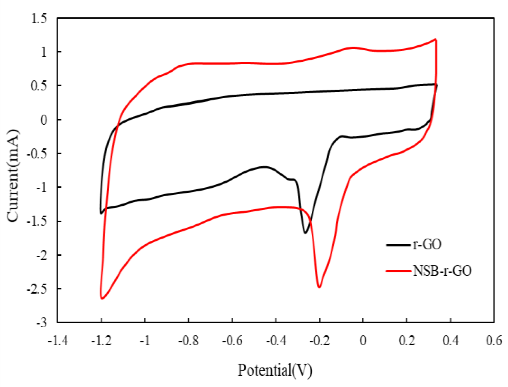
The reactivity of oxygens absorbed on GDEs could be clearly affected by the doping elements. The obvious oxygen reduction peaks in the potential range of −0.3 to −0.1 v in the cyclic voltammetry (CV) curves of r-GO and NSB-r-GO GDEs can be seen in Figure 3, but their peak values were about −0.26 V and −0.21 V, respectively, and those of NSB-r-GO GDE were more positive than the former. For the doping of N, S, and B hetero-atom elements, the CV areas of the NSB-r-GO GDE increased further, and its oxygen reactivity also increased.

3.1.3. Morphologies and Element Analysis

Carbon-based cathode materials for H2O2 generation, including r-GO, were selected due to their high conductivity and large specific surface areas, and some hetero-atoms, including N, S, and B, were also doped into their carbon-based skeletons. In addition, to avoid submerging and jamming the mesoporous GDE with an electrolyte, its surface was generally modified by adding amounts of the PTFE (polytetrafluoroethylene) emulsion to obtain hydrophobicity. Therefore, the internal structure of GDE used in this work was porous and hydrophobic and had a gas–liquid–solid three-phase contact surface, which ensures the transmission, diffusion, and reaction utilization of O2 to generate H2O2 smoothly.
The surficial morphologies of the r-GO and NSB-r-GO composites were only investigated via SEM and TEM analysis. Figure 4a,b shows that typical three-dimensional interconnecting frameworks could be observed in the SEM images of the r-GO and NSB-r-GO composites, but there were more surficial folds on the NSB-r-GO composite than that on r-GO.
Figure 4c,d shows that both the edges of the graphene nano-sheets of the r-GO and NSB-r-GO composites were wrinkled with wavy and transparent filaments caused by hypoxia, which could accelerate electron transfer and improve electro-catalytic performance. This phenomenon could be explained as follows: the graphene-based materials were doped with hetero-atom elements (N, S, and B) through the hydrothermal and reduction reacting processes, many non-uniform structural defects of active sites could be produced, and the NSB-r-GO composite had more folds and active sites than r-GO, which was more favorable to the electro-catalytic reaction.
The full XPS spectrums of the r-GO and NSB-r-GO composites are shown in Figure 5a. Besides the peaks values of C1s (284.8 eV) and O 1s (~532.63 eV and 530.37 eV), the other three characteristic peaks of N1s peaks (399.87 eV), S 2p peaks (164.27 eV), and B 1s peaks (193.45 eV) were also successfully detected in the NSB-r-GO composites. Figure 5b–d show that the hetero-atom elements N, S, and B had been successfully integrated into the graphene oxide skeleton. The electron density and charge distribution of adjacent carbon atoms in the graphene skeleton could be changed by the effective doping of hetero-atoms N, S, and B, by which the number of active sites and the hydrophilicity of the composites’ electrodes could be enhanced.
Thus, the NSB-r-GO composite with a larger specific surface area, more multiple pore sizes and abundant active sites, and higher catalytic activities was ultimately selected as the base composites of GDEs in this work [21]. It was not one or two kinds of elements, such as N and S, but all the N, S, and B elements that were doped into the graphene-based nickel foam mesh cathodes, which increased their adsorption performance on gaseous oxygen and polished the microstructure of GO composite electrodes. The gaseous oxygen was easily diffused into its porous surface, and the oxygen atom was absorbed easily on the GDE surface; then, the oxygen–oxygen bond would be lengthened and possibly broken into an active oxygen atom, which could ultimately be turned into H2O2.

3.1.4. Effects of pH, O2 Flow Rate, Current Density, and Reusage on the Production of H2O2

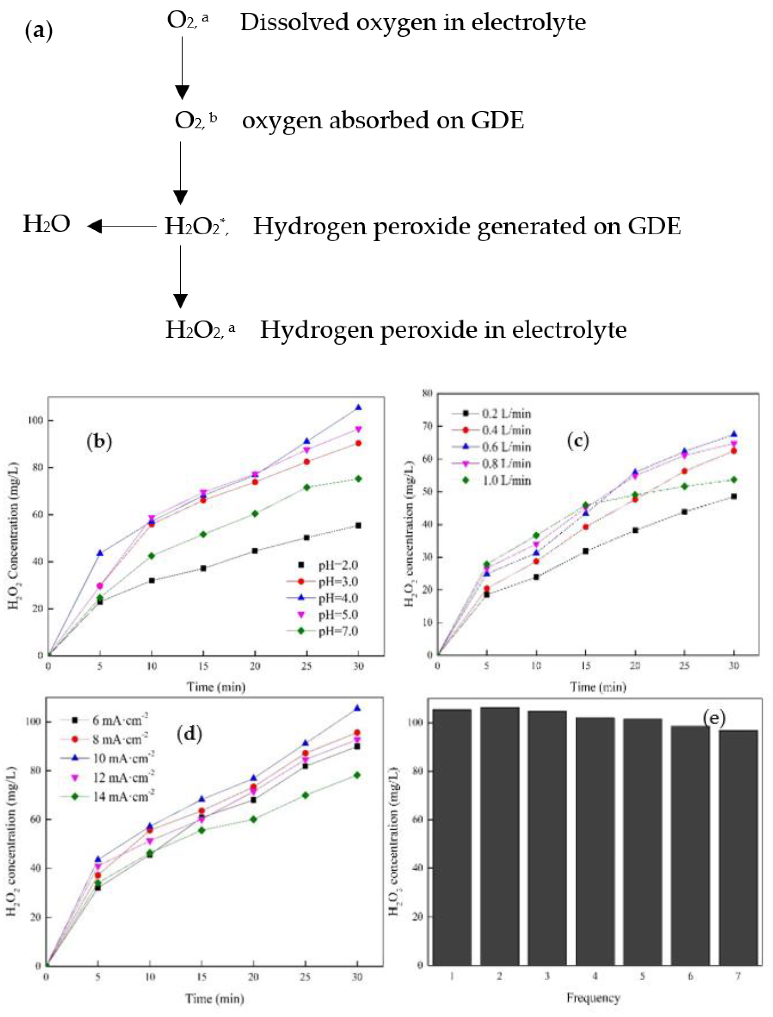
H2O2, as the main Fenton reagent, was generated on the GDE cathode from the absorbed dissolved O2 from aeration, and several main factors influencing the yield of H2O2, such as pH, O2 flow rate, current density, and reusage, were investigated in detail. The electrosynthesis of H2O2 was induced by the O2 two-electron reduction reaction (ORR), and O2 was diffused and dissolved on to the surface of GDE in the electrolyte. The mechanism of the O2 two-electron reduction reaction is shown in Figure 6a, where O2,a is the dissolved oxygen; O2,b is the adsorption of oxygen molecules on the surface of GDE; H2O2* is the H2O2 generated on the surface of GDE; H2O2 is H2O2 in the electrolyte.
As seen in Figure 6b, the maximum accumulated concentration of H2O2 was achieved when the pH value was 4.0; then, it could be decreased to 55.43 mg·L−1 when the pH was 2.0 or decreased to 75.26 mg·L−1 when the pH was 7. It seemed that a pH value of 3 to 6 was favorable for the production of H2O2. This was because excess H+ or OH would promote the decomposition or inhibition of H2O2, as shown in Equation (5).
H 2 O 2 + 2 H + + 2 e 2 H 2 O   ( E 0 = 1.770   V )
O 2 + 4 H + + 4 e 2 H 2 O 2   ( E 0 = 1.229   V )
As shown in Figure 6c, the production of H2O2 would increase when the O2 flow rate increased as well because a higher O2 flow rate could result in the rapid diffusion and dissolution of O2, which was favorable for the electrolytic reaction of O2 on the three-phase interfaces of GDE. For example, when the oxygen flow rate was 0.2 L·min−1, it took 30 min for the cumulative concentration of H2O2 to reach 48.53 mg·L−1. Thus, the production of H2O2 could be limited by insufficient oxygen supply, as shown in Equation (6) [22].
The influence of the current density on the production of H2O2 is shown in Figure 6d. When the current density increased from 5 mA·cm−2 to 10 mA·cm−2, the H2O2 yield increased from 89.91 mg·L−1 to 105.43 mg·L−1 in 30 min but decreased to 78.19 mg·L−1 when the current density was continuously increased to14 mA·cm−2; this was mainly because the transfer rate and numbers of the electrons in the oxygen reduction process increased after the current density increased, but too high currents may result in the decomposition and secondary reaction of H2O2.
The stability of GDE cathodes was verified by using the same cathode to measure the H2O2 yield for 7 times, as seen in Figure 6e. It decreased from 105.43 mg·L−1 to 96.81 mg·L−1 when used from the 1st to 7th time. It indicated that some tiny activated sites and three-phase interfaces were slightly damaged, which resulted in the decreased H2O2 yield.

3.2. Characteristics of CuFeO@C Particles

3.2.1. Surface Characterization of Heterogeneous CuFeO@C Particles

In this work, Fe2+ was supplied by heterogeneous CuFeO@C particles; therefore, it was necessary to testify whether ferric ion was synthesized into the particles by SEM and XRD analysis.
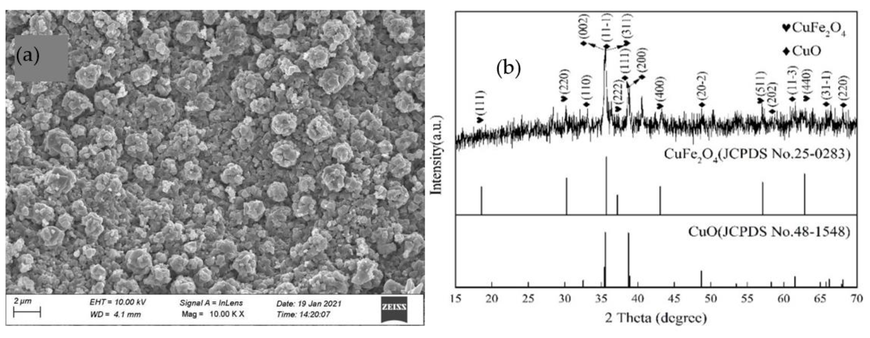
The surface morphology of CuFeO@C particles observed by SEM is shown in Figure 7a, and its main characteristic peaks of XRD spectrum are shown in Figure 7b. The characteristic diffraction peaks 2θ = 32.51°, 35.42°, 35.54°, 38.71°, 38.90°, 48.72°, 58.26°, 61.52°, 65.81°, 66.22°, and 68.12°, could align with the CuO lattice surfaces corresponding to (110), (002), (11-1), (111), (200), (20-2), (202), (11-3), (022), (31-1), and (220) (JCPDS card numbers 48-1548), respectively. Simultaneously, the characteristic diffraction peak 2θ = 18.51°, 30.17°, 35.64°, 37.18°, 43.04°, 57.05°, and 62.77° could match the (111), (220), (311), (222), (400), (511), and (440) crystal faces of CuFe2O4 (JCPDS card numbers 25-0283). These results indicated that the calcined CuFeO@C particles contained CuO and CuFe2O4 particles.
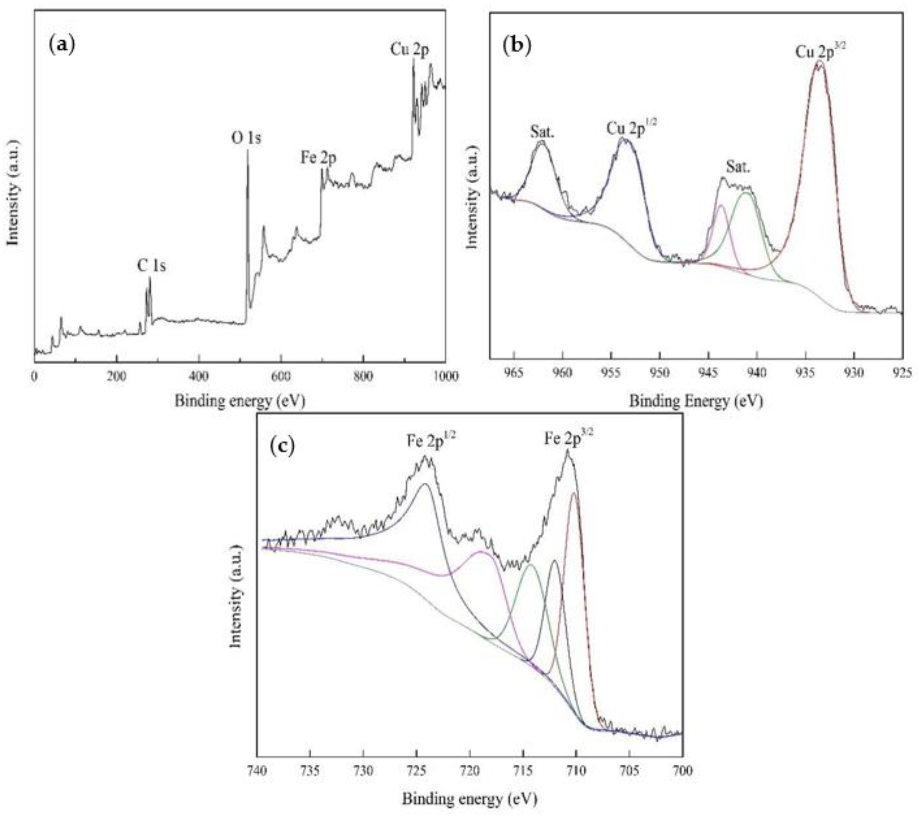
All the signals of Cu 2p, Fe 2p, O 1s, and C1s were detected in the full XPS spectrum of CuFeO@C in Figure 8a, and the binding energy peaks at 933.61 eV and 952.96 eV, shown in Figure 8b, corresponded to Cu 2p3/2 and Cu 2p1/2, respectively, and the difference between the two peaks was about 20 eV, which was consistent with the standard photoelectron peak of Cu (II), and the characteristic peak at 940.75 eV–943.41 eV and 961.89 eV corresponded to the presence of the Cu 2p3/2 and Cu 2p1/2 satellite peaks.
As shown in Figure 8c, two distinct peaks at 710.8 eV and 723.91 eV corresponded to Fe 2p3/2 and Fe 2p1/2, respectively. Among them, the Fe 2p3/2 spectrum could be divided into three peaks; their binding energies were 710.18, 712.3, and 713.96 eV, corresponding to octahedral Fe (II), octahedral Fe (III), and tetrahedral Fe (III), respectively. The results indicated that the catalytic function of Fe (II) to Fe (III) transformation may occur in the Fenton-like reactions [23,24].
If both the Fe (II) ion and H2O2 were generated from the cathodes, then the cathode must have excellent adsorption and reduction performance on gaseous oxygen and must simultaneously contain iron elements to release the Fe (II) ion to participate in the production of hydroxy radicals in time. It was reasonable to conclude that the structure of the cathodes mentioned above was complicated, and the efficiencies of the electro-Fenton process was possibly negatively affected by it. In this work, the Fe (II) ion was not supplied by anodes or cathodes made of iron but released from the suspended conductive particles, i.e., CuFeO@C particles [25].

3.2.2. Reuse of CuFeO@C Particles

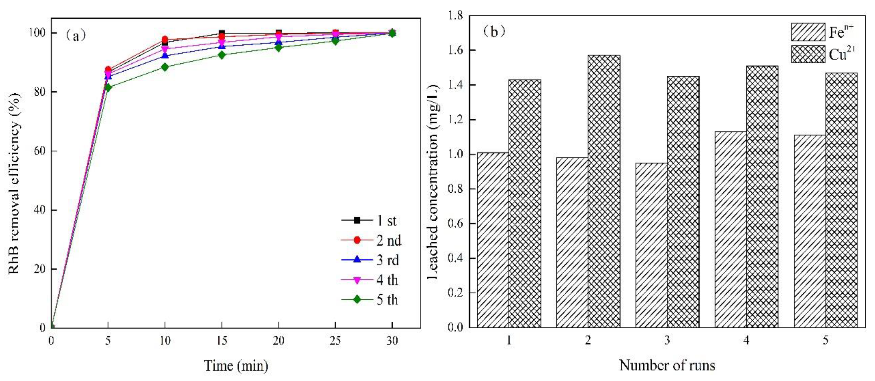
The stability of CuFeO@C particle electrodes was testified by using the same particles to decompose Rh B wastewater for 5 times, as seen in Figure 9a. Under the condition of 0.075 mol·L−1 electrolyte, initial concentration of 30 mg·L−1 Rh B and CuFeO@C 1.25 g·L−1, respectively, excellent degradations of Rh B were achieved every time. The only differences between them were that it took more electrolytic time to achieve the same degradation efficiencies of Rh B, while the reused times increased. On the other hand, there were about 1.0 mg·L−1 of iron ion and 1.4 mg·L−1 of copper ion dissolved in the electrolyte that were detected at every time, as shown in Figure 9b. The results indicated that the heterogeneous catalyst CuFeO@C had good reusability, stability, and catalytic performance in the electro-Fenton degradation of Rh B.

3.3. Degradation of Rh B by Electro-Fenton Process

3.3.1. Effects of Electrolytes

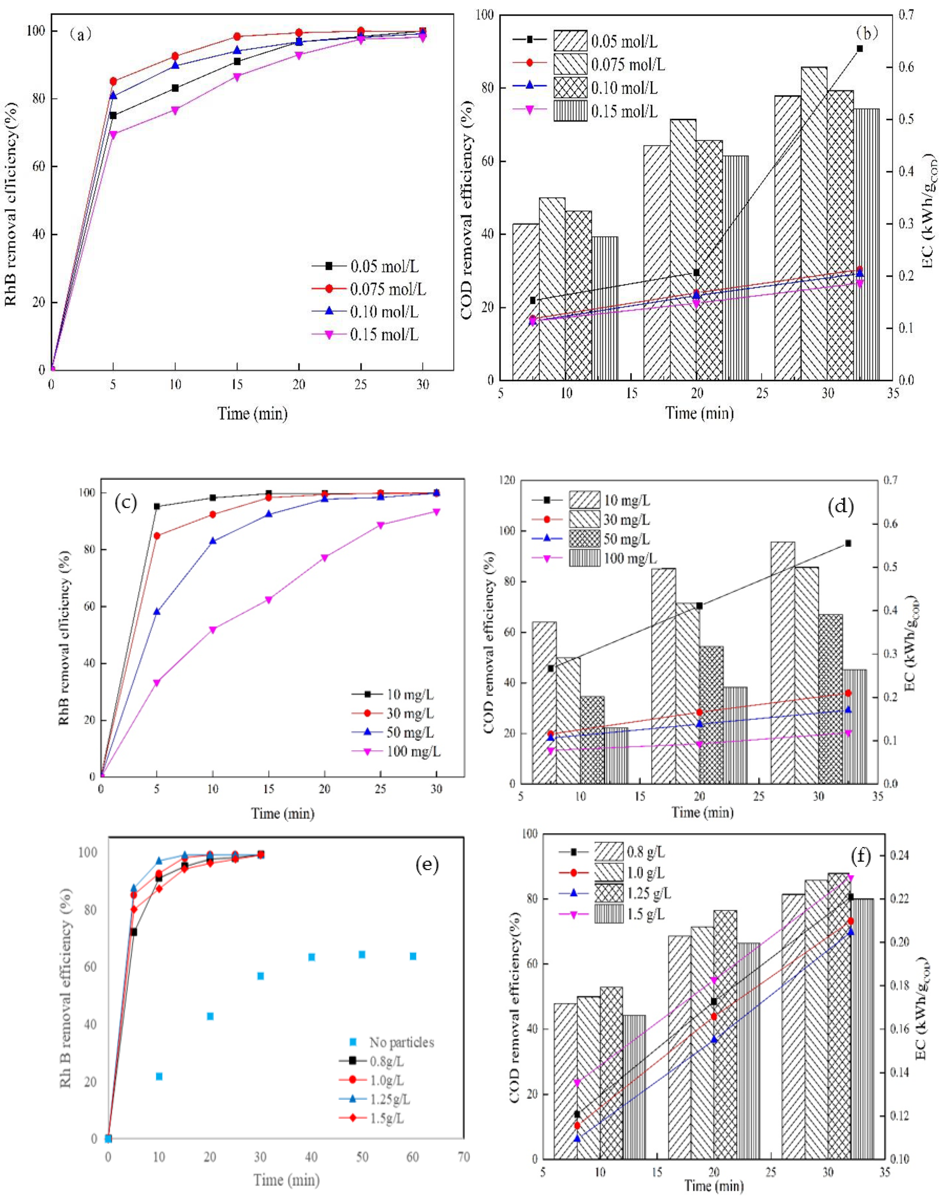
The conductivity of the wastewater could be enhanced, and the process of oxygen reduction to generate H2O2 could also be accelerated by the concentration levels of the electrolyte. Therefore, high-concentration electrolytes could result in the decrease in resistance, which contributes to electron transfer and the generating rate of H2O2. The experimental results shown in Figure 10a,b demonstrate that when the electrolyte concentrations increased from 0.05 mol·L−1 to 0.075 mol·L−1, the time required for the complete degradation of Rh B was shortened from 30 min to about 20 min, and the COD removal rate also increased to 85.71%, but when the electrolyte concentrations was continuously increased to 0.15 mol·L−1, the degradation and COD removal rates of Rh B were conversely decreased; therefore, the appropriate concentrations of the electrolytes were determined to be 0.075 mol·L−1.

3.3.2. Initial Rh B Concentrations

Under low concentrations of Rh B, the generated amounts of ·OH hydrogen free radicals could meet the oxidative degradation of Rh B, but under high concentrations, some Rh B molecules were likely adsorbed on the surfaces of the GDE cathode and heterogeneous CuFeO@C particles; thus, the high Rh B concentrations may negatively decrease the yield and utilization of ·OH. Alternatively, some ·OH may be consumed by the intermediates of Rh B degradation. The effects of the initial Rh B concentrations on degradation are shown in Figure 10c,d. When the initial Rh B concentrations were maintained at 10 mg·L−1, the removal rates of Rh B and COD reached 99% and 95.78% within 15 min, respectively; when it was increased to 100 mg·L−1, those of Rh B and COD only reached 93% and 45.26% within 30 min. The results indicated that the degradation rate decreased when the initial Rh B concentrations increased. This was because the amount of ·OH generated must be equivalent to the demand for the degradation of Rh B, and the excess Rh B molecules may be absorbed on the surfaces of cathodes and particle electrodes and result in negative effects on Rh B decomposition. Thus, 30 mg·L−1 was adopted as the initial Rh B concentration.

3.3.3. CuFeO@C Particle Concentrations

Under low heterogeneous CuFeO@C particle dosages, the concentrations of Fe2+ and Cu2+ released on the surface of CuFeO@C increased when the CuFeO@C particle concentrations was increased, which may ultimately promote the generation of more H2O2 and ·OH free radicals. However, when the CuFeO@C particle concentrations were too high, the CuFeO@C particles may cause the scavenging of ·OH and result in particle agglomeration.
The effects of CuFeO@C particles are shown in Figure 10e,f. When the dose of CuFeO@C increased from 0.8 g·L−1 to 1.25 g·L−1, the complete degradation of Rh B was achieved rapidly in 15 min, and simultaneously, the COD removal could reach 87.86%. However, when the dose of CuFeO@C increased to 1.5 g·L−1, both the Rh B and COD removal decreased slightly. This is because the activities of GDE and generated ·OH were possibly inhibited by excess CuFeO@C particles.

3.3.4. Simulated Wastewater Containing Anions and Other Organic Pollutants

The anions, including HCO3, NO3 and Cl, were regularly found in actual wastewater, and the effects on the degradation of Rh B is shown in Figure 11a,b. When added in 10 mmol·L−1 HCO3, both the removal efficiencies of Rh B and COD decreased; this is possibly because the ·OH may be reduced by the reaction with HCO3. When added with 10 mmol·L−1 NO3 or Cl, the degradation of both Rh B and COD increased slightly; this is because Cl could be reduced to Cl2 at the anode and transformed into HCIO, which could directly attack pollutants and accelerate the degradation of Rh B.
The applicability of the electro-Fenton process to other organic pollutants was investigated, and the results are shown in Figure 12a. All pollutants, such as initial 30 mg·L−1 of phenol, methylene blue, and amoxicillin, were almost completely decomposed in 30 min; therefore, the electro-Fenton process could be used to treat many kinds of pollutants besides Rh B in wastewater.

3.3.5. Pathway of RhB Degradation by Electro-Fenton Process

The RhB was decomposed by the electro-Fenton process, in which the free radicals were generated and participated; its degradation mechanism could be tested by activity inhibition experiments on hydroxyl free radicals (·OH). The tertiary butyl alcohol (TBA), as a typical scavenging agent of ·OH, was selected as the free radical quencher in this work, and amounts of generated ·OH could be rapidly consumed by it. Thus, the decomposition process of Rh B could also be affected. Figure 12b shows that when the added TBA solution concentrations were designated as 0 mmol·L−1, 10 mmol·L−1, and 20 mmol·L−1, respectively, the degradation of Rh B decreased significantly. With increased TBA concentrations, the inhibition effects on the Rh B degradation would become more and more severe, which indirectly proved the function of ·OH radicals in Rh B degradation through the electro-Fenton process.
As known, both H2O2 and ferrous sulfate were necessary to be added into wastewater to carry out the conventional Fenton process, but in this work, neither H2O2 nor ferrous sulfate was added outside because H2O2 was generated from O2 in situ on the GDE cathode and Fe2+ was released simultaneously from the surface of CuFeO@C particles. In particular, the internal structure of NSB-r-GO-GDE was mesoporous and conductive and had large specific surface areas, great adsorption capacity, and large amounts of active sites; all these characteristics were favorable to easily change oxygen into hydroxy radicals. For CuFeO@C particles, all octahedral Fe (II), octahedral Fe (III), and tetrahedral Fe (III) particles were observed in it, and about 1 mg·L−1 was detected in the wastewater, which proved that Fe (II) could be released steadily from the CuFeO@C particles to participate in the Fenton process. Therefore, the electro-Fenton process can be carried out with the GDE cathode and CuFeO@C particles and accelerated because the CuFeO@C particles were polarized into tiny negative and positive electrodes and worked as particle electrodes in the electrolysis process, which could be regarded as a three-dimensional electrochemical reactor (TDER). This process is shown in Figure 13.

4. Conclusions

The electro-Fenton reactor was mainly composed of the GDE cathode and CuFeO@C particles. Compared with the r-GO -GDE cathode, the NSB-r-GO-GDE cathode had more abundant pores, specific surface areas, and active sites and was more favorable to produce H2O2 in situ.
The CuFeO@C composed of CuO and CuFe2O4 could be used as a heterogeneous catalyst to produce the Fe 2+ ion in situ in the Fenton process and as conductive particle electrodes in this conceptual three-dimensional electrochemical reactor, which was constructed with the GDE cathode, Ti/RuSn anode, and heterogeneous CuFeO@C particle electrodes. The Fe 2+ ion was not generated by anodes or cathodes containing iron but released from the suspended conductive CuFeO@C particles.
For all Fenton reagents that could be generated in situ, no chemical reagent was necessary to be externally added to complete the electro-Fenton process, and it could be used to treat organic wastewater rather than the conventional Fenton reaction.

Author Contributions

S.L., S.G., X.J., X.S. and Y.L.: writing—original draft preparation, project administration, data curation, formal analysis, investigation, visualization; Y.Z., Y.D. (Yunmei Du) and Y.D. (Yuanhong Ding): funding acquisition, administration, conceptualization, writing—review and editing. All authors have read and agreed to the published version of the manuscript.

Funding

This research and APC was funded by the Foundation of Shandong Science and Technology Project (2022TSGC2539), the National Natural Science Foundation of China (52302274), and Natural Science Foundation of Shandong Province, China (ZR2022QE098).

Data Availability Statement

The raw data supporting the conclusions of this article will be made available by the authors upon request.

Conflicts of Interest

The authors declare that they have no known competing financial interests or personal relationships that could have appeared to influence the work reported in this paper.

References

  1. Tang, L.; Yu, J.; Pang, Y.; Zeng, G.; Deng, Y.; Wang, J.; Ren, X.; Ye, S.; Peng, B.; Feng, H. Sustainable efficient adsorbent: Alkali-acid modified magnetic biochar derived from sewage sludge for aqueous organic contaminant removal. Chem. Eng. J. 2018, 336, 160–169. [Google Scholar] [CrossRef]
  2. Mashkoor, F.; Nasar, A.; Inamuddin; Asiri, A.M. Exploring the Reusability of Synthetically Contaminated Wastewater Containing Crystal Violet Dye using Tectona grandis Sawdust as a Very Low-Cost Adsorbent. Sci. Rep. 2018, 8, 8314. [Google Scholar] [CrossRef]
  3. Rambabu, K.; Bharath, G.; Monash, P.; Velu, S.; Banat, F.; Naushad, M.; Arthanareeswaran, G.; Show, P.L. Effective treatment of dye polluted wastewater using nanoporous CaCl2 modified polyethersulfone membrane. Process Saf. Environ. Prot. 2019, 124, 266–278. [Google Scholar] [CrossRef]
  4. Asadollahfardi, G.; Zangooei, H.; Motamedi, V.; Davoodi, M. Selection of coagulant using jar test and analytic hierarchy process: A case study of Mazandaran textile wastewater. Adv. Environ. Res. 2018, 7, 1–11. [Google Scholar]
  5. Al-Alwani, M.A.M.; Ludin, N.A.; Mohamad, A.; Kadhum, A.H.; Mukhlus, A. Application of dyes extracted from Alternanthera dentata leaves and Musa acuminata bracts as natural sensitizers for dye-sensitized solar cells. Spectrochim. Acta Part A Mol. Biomol. Spectrosc. 2018, 192, 487–498. [Google Scholar] [CrossRef] [PubMed]
  6. Bassyouni, D.G.; Hamad, H.A.; El-Ashtoukhy, E.S.Z.; Amin, N.K.; Abd El-Latif, M.M. Comparative performance of anodic oxidation and electrocoagulation as clean processes for electrocatalytic degradation of diazo dye Acid Brown 14 in aqueous medium. J. Hazard. Mater. 2017, 335, 178–187. [Google Scholar] [CrossRef]
  7. Li, N.; An, J.; Zhou, L.; Li, T.; Li, J.; Feng, C.; Wang, X. A novel carbon black graphite hybrid air-cathode for efficient hydrogen peroxide production in bioelectrochemical systems. J. Power Sources 2016, 306, 495–502. [Google Scholar] [CrossRef]
  8. Zhou, W.; Meng, X.; Gao, J.; Alshawabkeh, A.N. Hydrogen peroxide generation from O2 electroreduction for environmental remediation: A state-of-the-art review. Chemosphere 2019, 225, 588–607. [Google Scholar] [CrossRef]
  9. Zhang, M.; Tao, H.; Liu, Y.; Yan, C.; Hong, S.; Masa, J.; Robertson, A.W.; Liu, S.; Qiu, J.; Sun, Z. Ultrasound-Assisted Nitrogen and Boron Co-doping of Graphene Oxide for Efficient Oxygen Reduction Reaction. ACS Sustain. Chem. Eng. 2019, 7, 3434–3442. [Google Scholar] [CrossRef]
  10. Lu, K.Q.; Yuan, L.; Xin, X.; Xu, Y.-J. Hybridization of graphene oxide with commercial graphene for constructing 3D metal-free aerogel with enhanced photocatalysis. Appl. Catal. B Environ. 2018, 226, 16–22. [Google Scholar] [CrossRef]
  11. Jiang, Y.; Ni, P.; Chen, C.; Lu, Y.; Yang, P.; Kong, B.; Fisher, A.; Wang, X. Selective Electrochemical H2O2 Production through Two Electron Oxygen Electrochemistry. Adv. Energy Mater. 2018, 8, 1801909. [Google Scholar] [CrossRef]
  12. Sun, Z.H.; Yan, Z.Q.; Yue, K.C.; Li, A.; Qian, L. Novel high-performance electromagnetic absorber based on Nitrogen/Boron co-doped reduced graphene oxide. Compos. Part B Eng. 2020, 196, 108132. [Google Scholar] [CrossRef]
  13. Liu, J.L.; Zhu, Y.R.; Chen, X.H.; Yi, W. Nitrogen, sulfur and phosphorus tri-doped holey graphene oxide as a novel electrode material for application in supercapacitor. J. Alloys Compd. 2020, 815, 152328. [Google Scholar] [CrossRef]
  14. Meki, K.; Wang, Z.; Jing, B.; Qiu, S.; Deng, F. Enhanced electrochemical O2 reduction to H2O2 through resilient hybrid catalysts modified with DMSO in electro-Fenton. Sep. Purif. Technol. 2024, 346, 127490. [Google Scholar] [CrossRef]
  15. Liu, Y.; Kong, C.; Liu, L.; Jiang, X.; Liu, C.; Liu, F.; Sun, J.; Wang, Y. Progress in copper-based supported heterogeneous electro-Fenton catalysts. Chem. Eng. J. 2024, 486, 150217. [Google Scholar] [CrossRef]
  16. Labiadh, L.; Ammar, S.; Kamali, A.R. Oxidation/mineralization of AO7 by electro-Fenton process using chalcopyrite as the heterogeneous source of iron and copper catalysts with enhanced degradation activity and reusability. J. Electroanal. Chem. 2019, 853, 10–32. [Google Scholar] [CrossRef]
  17. Zahrani, A.A.; Ayati, B. Using heterogeneous Fe-ZSM-5 nanocatalyst to improve the electro Fenton process for acid blue 25 removal in a novel reactor with orbiting electrodes. J. Electroanal. Chem. 2020, 873, 114456. [Google Scholar] [CrossRef]
  18. Khandelwal, M.; Li, Y.; Hur, S.H.; Chung, J.S. Surface modification of co-doped reduced graphene oxide through alkanolamine functionalization for enhanced electrochemical performance. New J. Chem. 2018, 42, 1105–1114. [Google Scholar] [CrossRef]
  19. Mannan, M.A.; Hirano, Y.; Quitain, A.T.; Koinuma, M.; Kida, T. Graphene Oxide to, B. N Co-doped Graphene through Tris-dimethylaminoborane Complex by Hydrothermal Implantation. Am. J. Mater. Sci. 2019, 9, 22–28. [Google Scholar]
  20. Prakash, D.; Manivannan, S. N, B co-doped and Crumpled Graphene Oxide Pseudocapacitive Electrode for High Energy Supercapacitor. Surf. Interfaces 2021, 23, 101025. [Google Scholar] [CrossRef]
  21. Yang, W.; Zhou, M.; Oturan, N.; Li, Y.; Oturan, M.A. Electrocatalytic destruction of pharmaceutical imatinib by electro-Fenton process with graphene-based cathode. Electrochim. Acta 2019, 305, 285–294. [Google Scholar] [CrossRef]
  22. Xia, Y.; Shang, H.; Zhang, Q.; Zhou, Y.; Hu, X. Electrogeneration of hydrogen peroxide using phosphorus-doped carbon nanotubes gas diffusion electrodes and its application in electro-Fenton. J. Electroanal. Chem. 2019, 840, 400–408. [Google Scholar] [CrossRef]
  23. Petran, A.; Radu, T.; Culic, B.; Turcu, R. Tailoring the properties of magnetite nanoparticles clusters by coating with double inorganic layers. Appl. Surf. Sci. 2016, 390, 1–6. [Google Scholar] [CrossRef]
  24. Li, J.; Yan, J.F.; Yao, G.; Zhang, Y.; Li, X.; Lai, B. Improving the degradation of atrazine in the three-dimensional (3D) electrochemical process using CuFe2O4 as both particle electrode and catalyst for persulfate activation. Chem. Eng. J. 2019, 361, 1317–1332. [Google Scholar] [CrossRef]
  25. Peng, M.; He, J.; An, J.; Xie, T.; Zhao, T.; Li, G. Establishment of a reagent-free three-dimensional electro-Fenton system for high H2O2 production and efficient degradation of Roxarsone. Chem. Eng. J. 2023, 477, 146963. [Google Scholar] [CrossRef]
Figure 1. Schematic diagram of experimental electro-Fenton process.
Water 16 02906 g001
Figure 2. Nitrogen adsorption–desorption isotherms (a) and corresponding pore size distribution curves (b) of r-GO and NSB-r-GO composites.
Water 16 02906 g002
Figure 3. Cyclic voltammetry curves of oxygen reduction for modified GDEs.
Water 16 02906 g003
Figure 4. SEM and TEM morphologies of r-GO (a,c) and NSB-r-GO (b,d).
Water 16 02906 g004
Figure 5. XPS full spectrum of r-GO and NSB-r-GO composites (a), N 1s spectrum of NSB-r-GO composites (b), S 2p spectrum of NSB-r-GO composites (c), and B 1s spectrum of NSB-r-GO composites (d).
Water 16 02906 g005
Figure 6. The path of generated hydrogen peroxide (a) and the effects of pH (b), O2 flow rate (c), current density (d), and reused times on H2O2 production (e).
Water 16 02906 g006
Figure 7. SEM image (a) and XRD spectrum (b) of heterogeneous catalyst CuFeO@C.
Water 16 02906 g007
Figure 8. XPS full spectrum of heterogeneous catalyst CuFeO@C (a), Cu 2p spectrum of heterogeneous catalyst CuFeO@C (b), Fe 2p spectrum of heterogeneous catalyst CuFeO@C (c).
Water 16 02906 g008
Figure 9. Reusability of heterogeneous catalyst CuFeO@C: (a) the removal rate of Rh B by used times; (b) the effect of used times on the dissolved concentrations of metal ions.
Water 16 02906 g009
Figure 10. Effects of electrolytes (a,b), initial Rh B (c,d), and CuFeO@C concentrations (e,f).
Water 16 02906 g010
Figure 11. Effects of coexisting anions (a,b) on the degradation of Rh B.
Water 16 02906 g011
Figure 12. Applicability of the electro-Fenton process to organic pollutants (a) and effect of hydroxyl radicals (b).
Water 16 02906 g012
Figure 13. Degradation pathway of Rh B.
Water 16 02906 g013
Table 1. BET results of r-GO and NSB-r-GO composites.
SamplesSpecific Surface Area (m2·g−1) Pore Volume (cm3·g−1) Pore Size (nm)
r-GO composites23.7930.1053.805
NSB-r-GO composites46.4910.0983.805
Disclaimer/Publisher’s Note: The statements, opinions and data contained in all publications are solely those of the individual author(s) and contributor(s) and not of MDPI and/or the editor(s). MDPI and/or the editor(s) disclaim responsibility for any injury to people or property resulting from any ideas, methods, instructions or products referred to in the content.