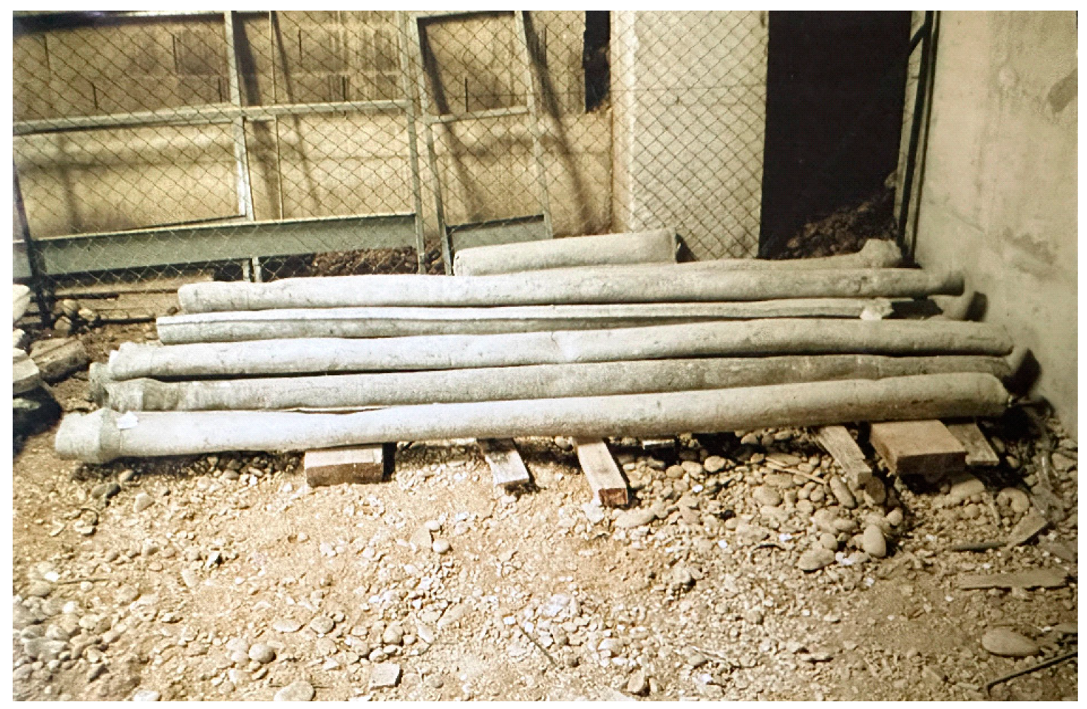
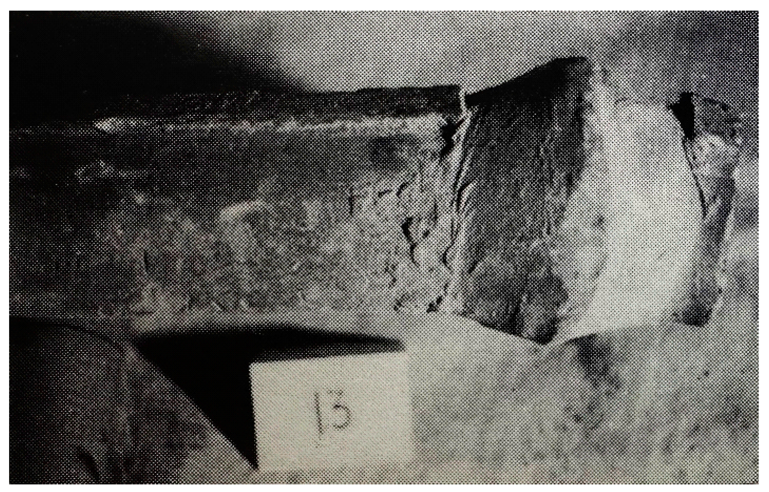
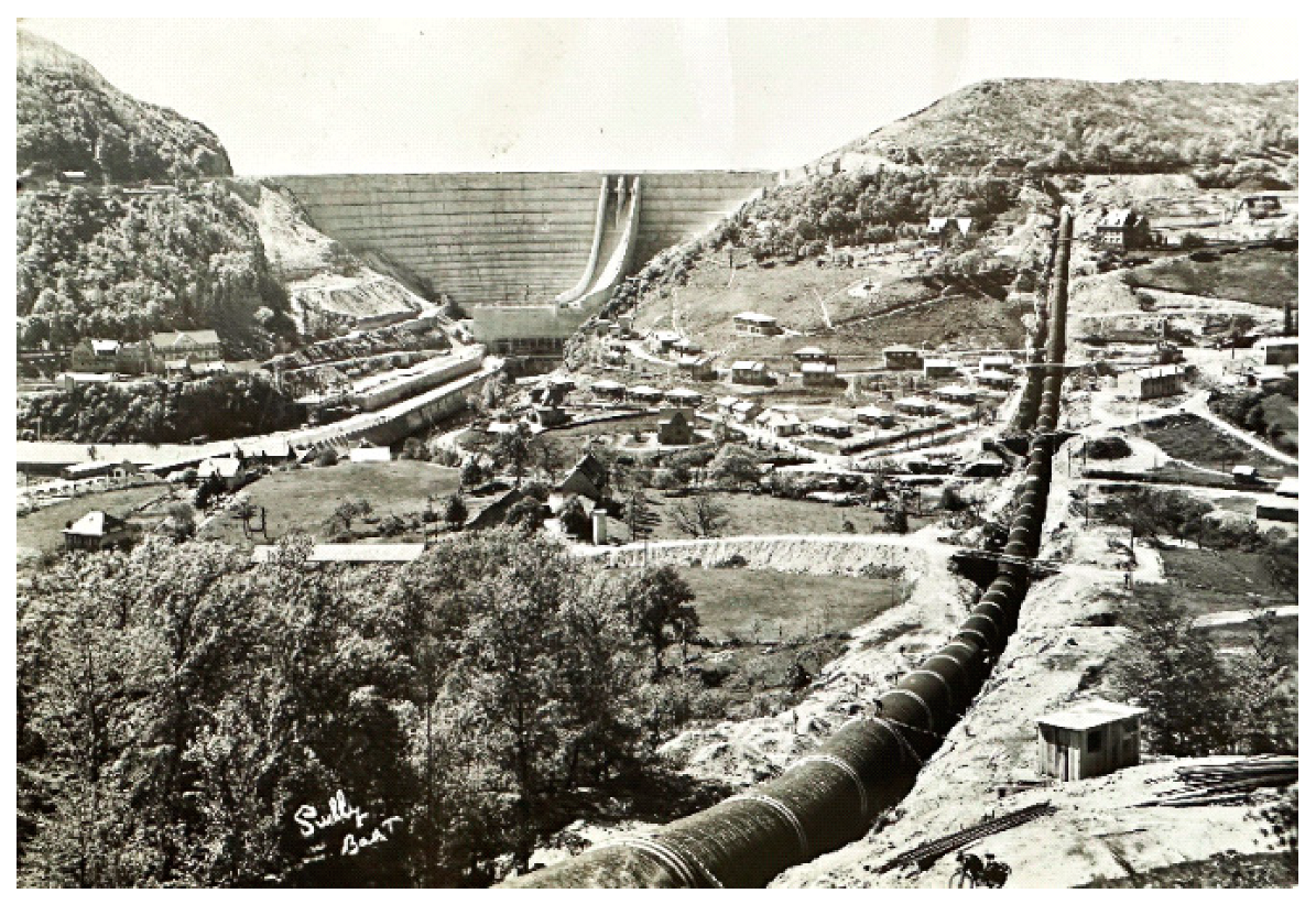
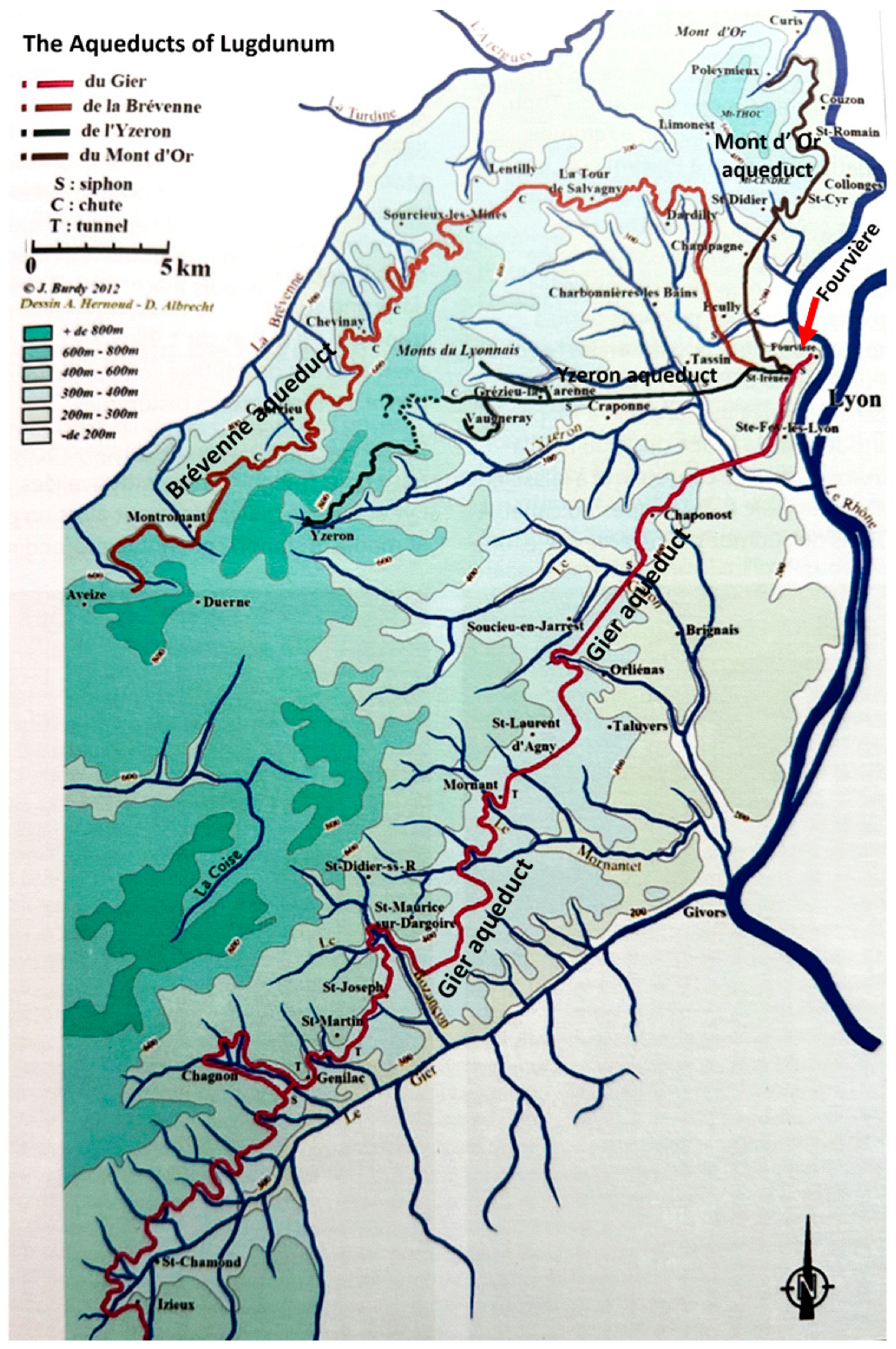
2. History
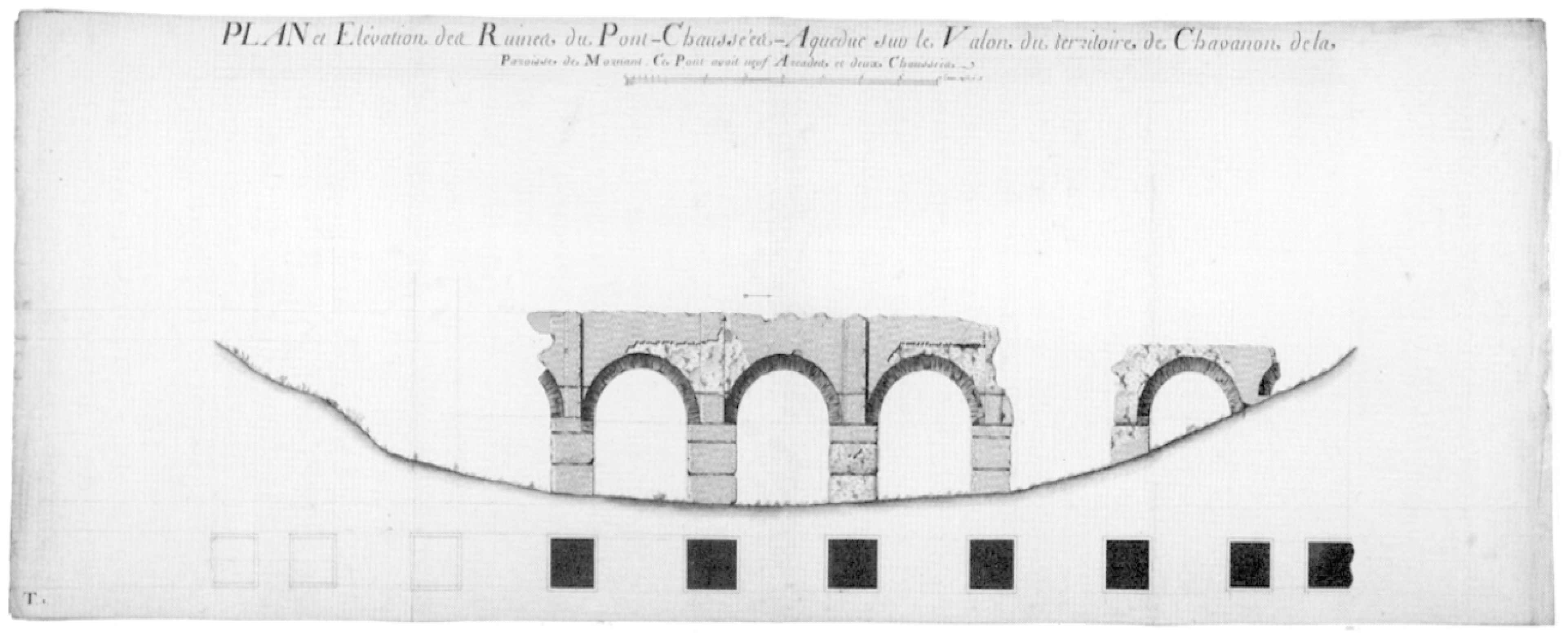
The water provision of Lugdunum has attracted the attention of writers in the past who produced books and images of parts of the aqueducts. First mention of Lyon’s Roman aqueducts date from the 16th century, referring to channels passing close to, or through, villages. Then, in 1759, Guillaume Marie Delorme gave a lecture at the
Académie de Sciences, Belles-Lettres et Arts de Lyon on his ‘
Recherches sur les Aqueducs de Lyon construites par les Romains’, discussing the remains of the Gier aqueduct, and of parts of the Brevenne and the Yzeron aqueducts. A year later, the lecture was published in a 60-page book which was well received by water scholars of that era (
Figure 6). Continuing his researches in later years, Delorme produced a great number of engravings measuring 55 × 82 cm, a total of 126, all of which depict the investigated remains of the Gier aqueduct, as well as two engravings of the Brevenne aqueduct and one of the Yzeron aqueduct. After the death of Delorme in 1782, and of his pupil and friend Catherin-François Boulard in 1794, the engravings were in 1803 offered to the city of Lyon, which, however, refused to buy them.
Only mentioned in 1818 in a letter, the engravings were considered lost. After two centuries, they miraculously reappeared in October 2003 in Paris, now to be acquired by the city of Lyon with the subvention, among others, by the Water Company
la Générale des Eaux. Today, the engravings are kept at the City Archives of Lyon (
Figure 7). In 2015, a publication about these high-quality engravings was issued by the organization
L’Arraire [
4], p.17.
In the 19th century, several authors such as Maudet de Penhouet, Alexandre Flachéron (who proposed a functional restoration of the Brévenne aqueduct), Paul Gasparin, François Gabut, Achille Raverat, and Louis Bresson contributed to the knowledge of the Lyon aqueducts, with some publications, however, being lost while parts of presented data proved incorrect in later days [
5]. Then, in 1909, the thesis by Camille Germaine de Montauzan (1862–1942) appeared describing the Roman aqueducts of Lyon, their water provision and hydraulics engineering, their organization and administration, and the construction techniques together with legal matters—this a great work and reference book of 436 pages [
6].
It was only in the late 1960s that aqueduct enthusiasts as Jean Burdy, Louis Jeancolas, Henri Bougnol and others started research again, now supported in the 1980s by AFAN (Association pour les Fouilles Archéologiques Nationales) and INRAP (Institut National de Recherches Archéologiques Préventives). Jean Burdy published over the years 1987–1996 four monographs, one for each aqueduct, presenting the results of the investigations and leading to his doctorate in 1996 at the Lyon University (Burdy [
3,
5,
7,
8,
9]. On numerous occasions, Jean Burdy reported of his findings, among others, for the
Union des Sociétés Historques de Rhône,
the Société Natiionale de Antiquaires de France, the
Académie des Sciences, Belles-Lettres et Arts de Lyon, and at the international conferences of the German Frontinus Gesellschaft and the Deutsche Wasser Historische Gesellschaft DWhG. In November 2023, a conference on the historic water provision of Lyon named ‘
Premieres Assises de Patrimoine Hydraulique’, 22–25 November 2023 was organized. It was attended by Jean Burdy, then at the age of 93.
4. The Aqueduct of Mont d’Or
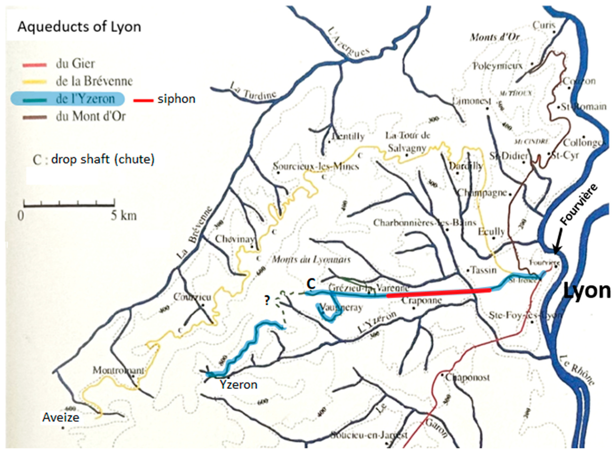
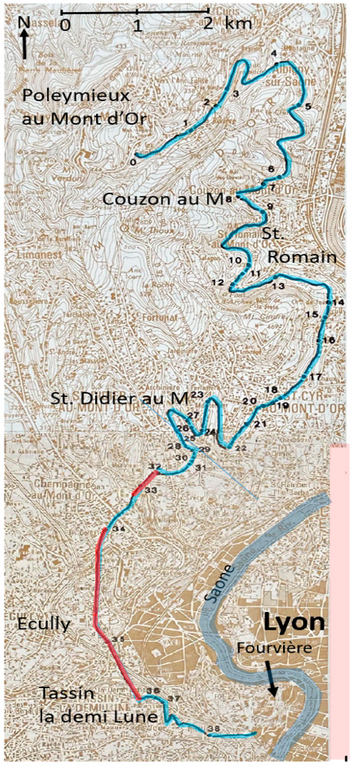
Near the Poleymieux village in the up to 600 m high mountain range of the Mont d’Or, at about 372 m elevation and 10 km north of Lyon, the 26 km aqueduct took its origin (no. 0 on the map of
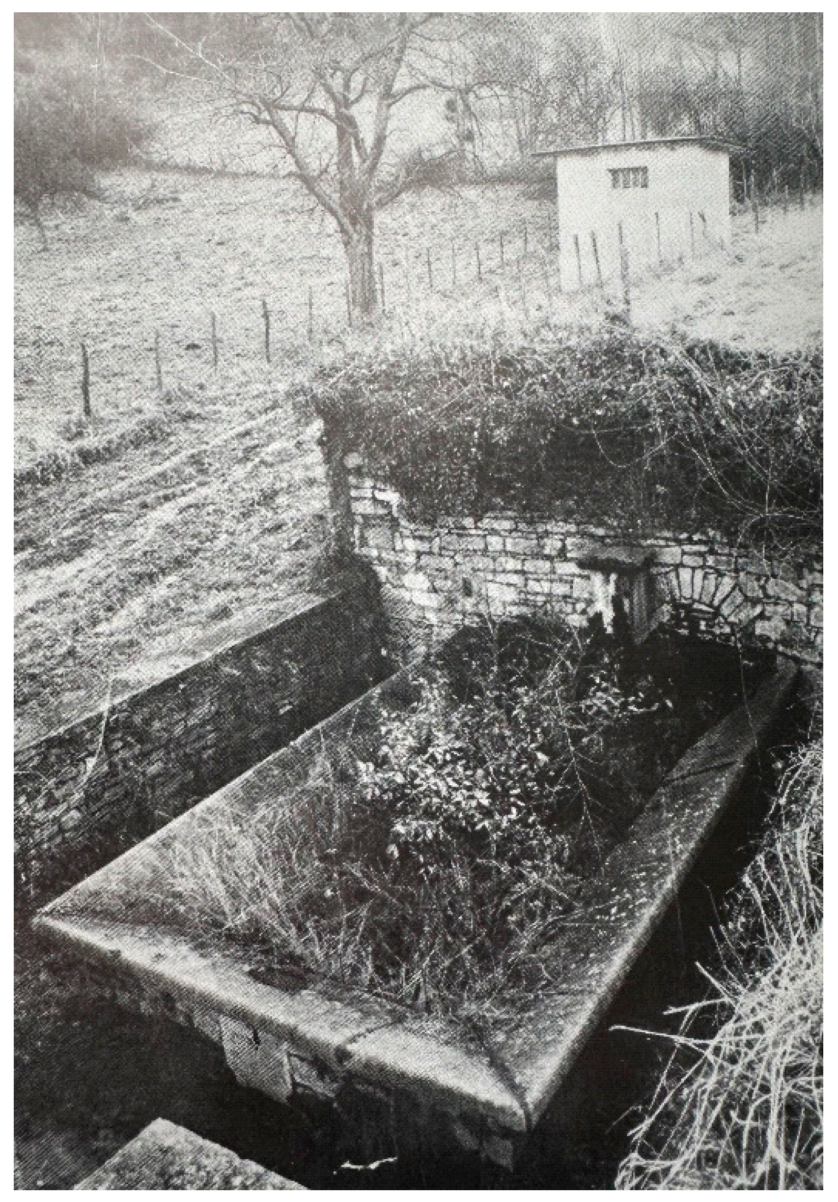
Figure 8). It was built ca. 20 BCE under the reign of Augustus (Burdy 1987, 16). The old water catchment system had long since been replaced by an underground chamber connected to a gallery that fed a washing basin; today, a modern installation performs the task of water collecting (
Figure 9). First remains of the channel appear 650 m downstream at the north east, no. 1 on the
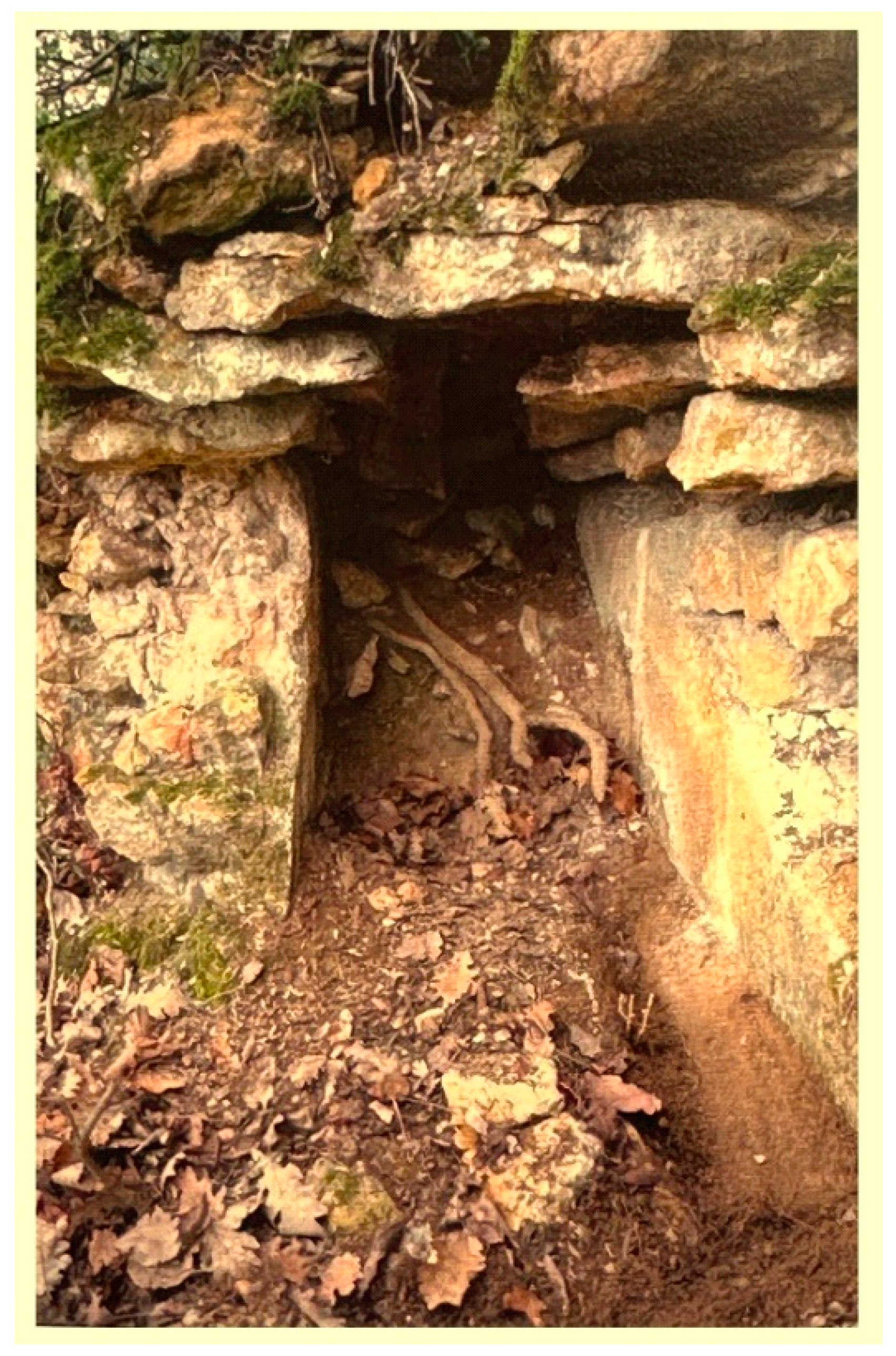
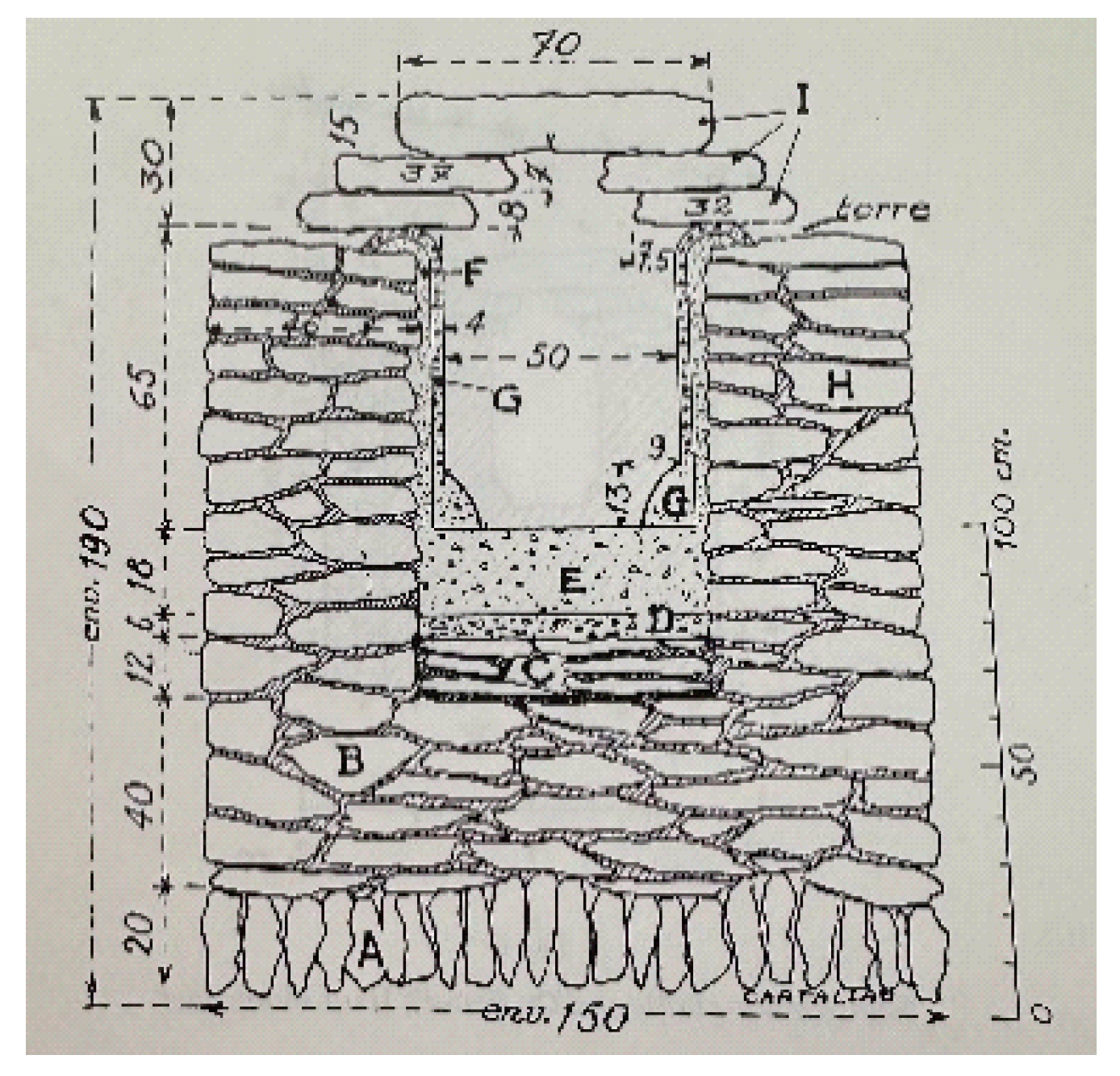
Figure 9 map, while the intact channel was found at no. 3, measuring 50 cm wide and 65 cm high, covered by stone slabs (
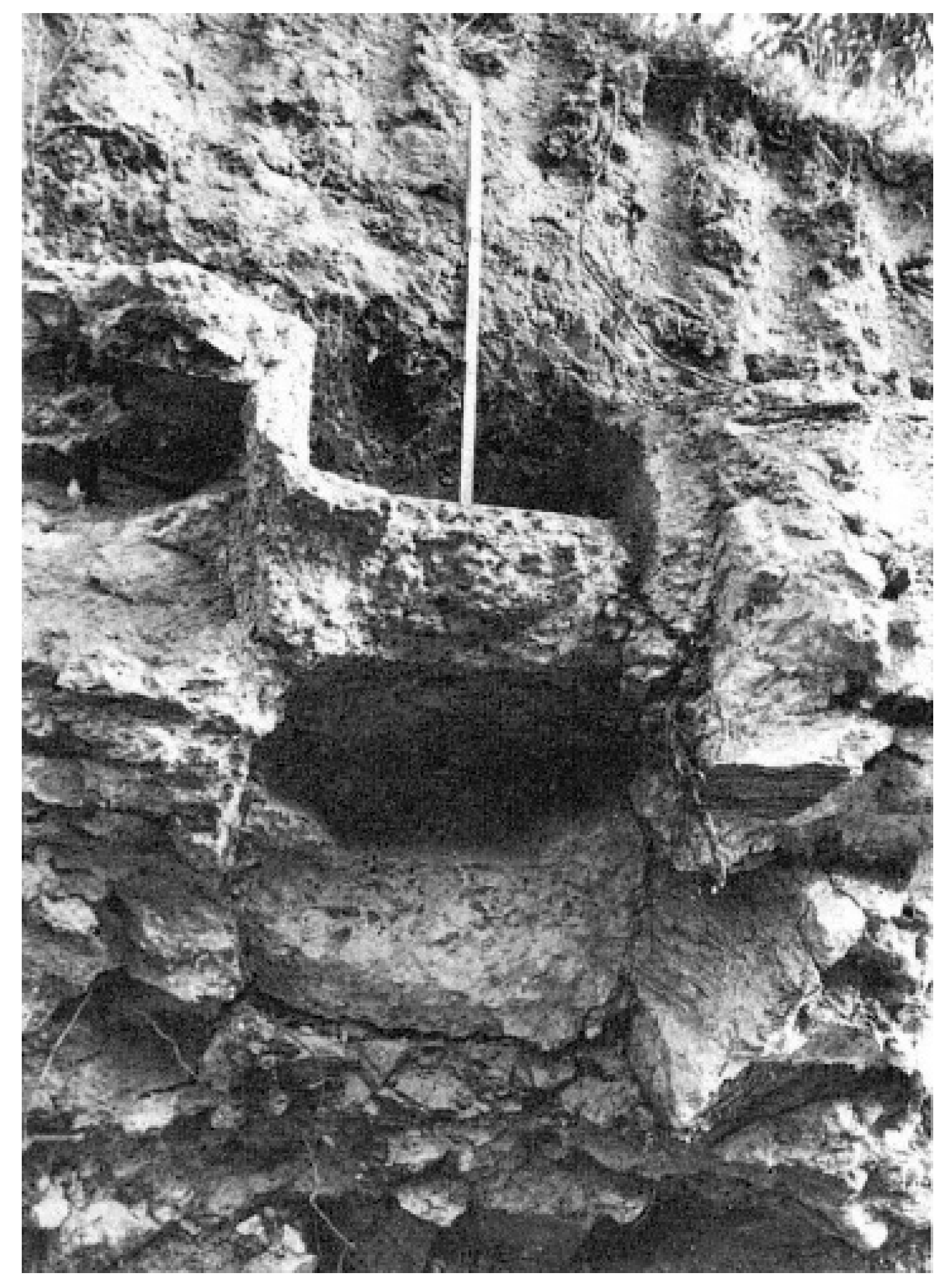
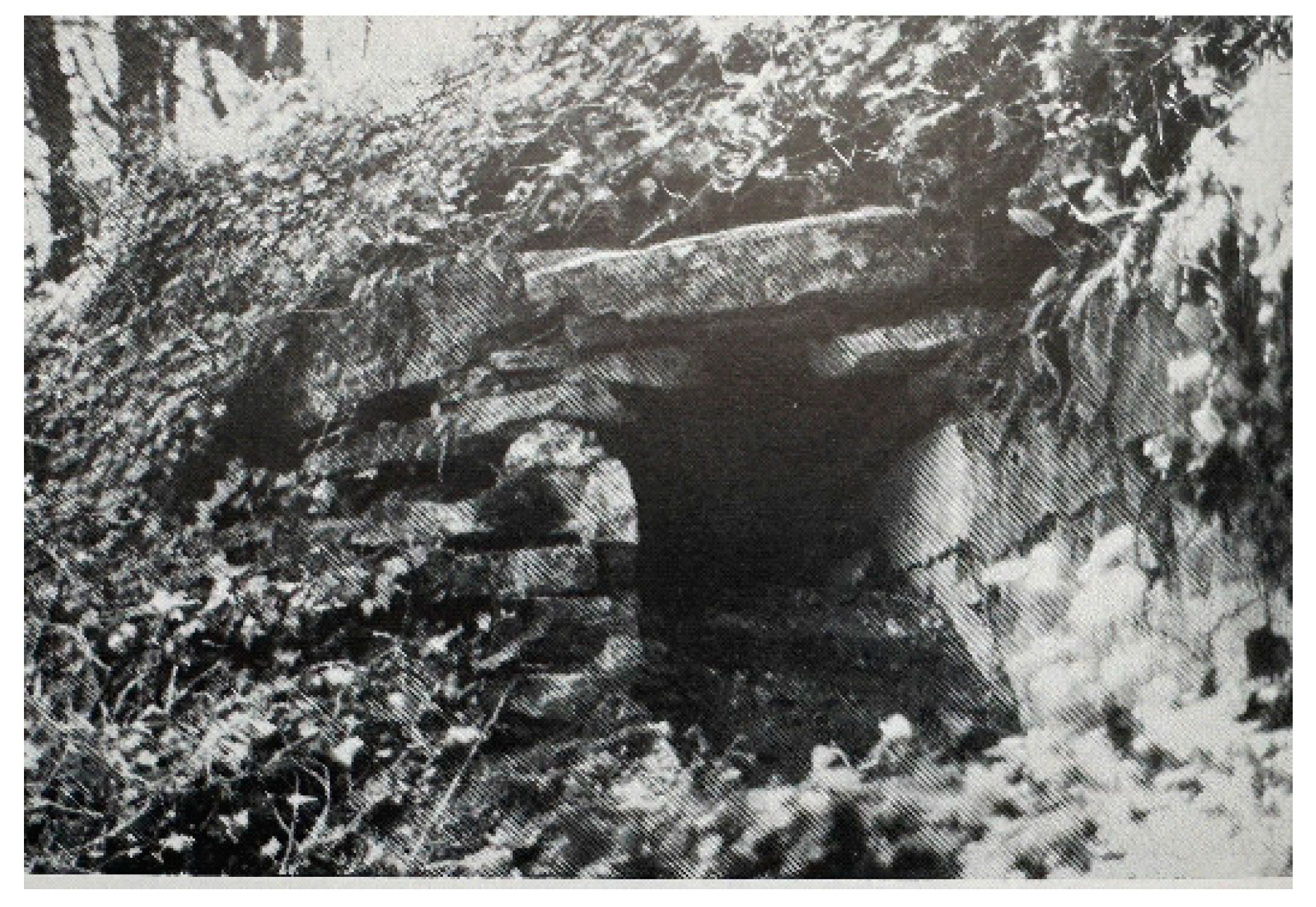
Figure 10). The channel then, after some turns, changed direction to the south where at Couzon au Mont d’Or the channel appeared again, without its cover, (no. 8,
Figure 11) at a level of 311 m. Channel remains were spotted on several locations further downstream as indicated on the map, for instance, at St. Romain au Mont d’Or, no. 12. (
Figure 12 and
Figure 13), where an additional spring was tapped, and at St. Didier au Mont d’Or (no. 27).
Downstream of point 31 on the map, the deep valley of the Limonest stream was crossed by a 30 m deep and 420 m long siphon, a header tank at 285 m (no. 32 on the map) and a receiving tank at a supposed 277 m height (
Figure 14) (for siphons/pressure lines in ancient aqueducts, see [
1]). The remains of the about 12 arches of the 100 m long and 17 m high siphon bridge (point no. 33) have all disappeared (
Figure 15).
At no. 34 on the map, the header tank of a second and much larger siphon ‘
de ruisseau des Planches’ was located, 3500 m long and 70 m deep, with a 200 m long and 25 m high siphon bridge, the remains of which were torn down in 1967 (
Figure 16) [
7], p. 90.
The conduits of the siphons are thought to be made of lead and several pipes laid out parallel, maybe six or eight, for the great siphon as Jean Burdy envisages, but no traces of the pipes have remained [
7], p. 27; [
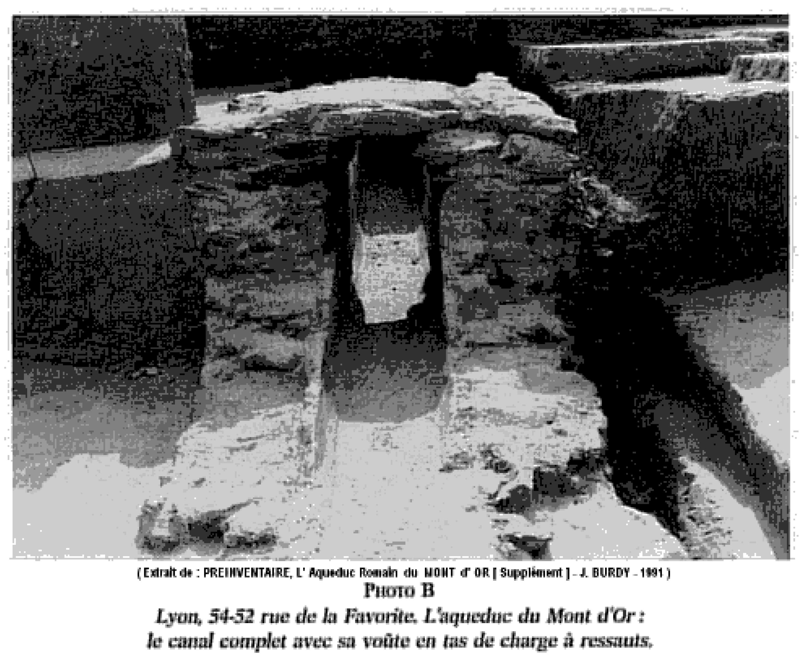
2], p. 21. Downstream of the siphon and barely visible are some remains of the channel that are to be found at points no. 36 and 37 on the sides of an excavation for a train track end in the 19th century that destroyed a 120 m long aqueduct section. Point 38 relates to a finding of the channel in perfect condition in the Rue de la Favorite, probably discovered during activities for building construction in the first half of last century (
Figure 17). From there, the channel took a slightly east/north-eastern course via the
Point du Jour and the
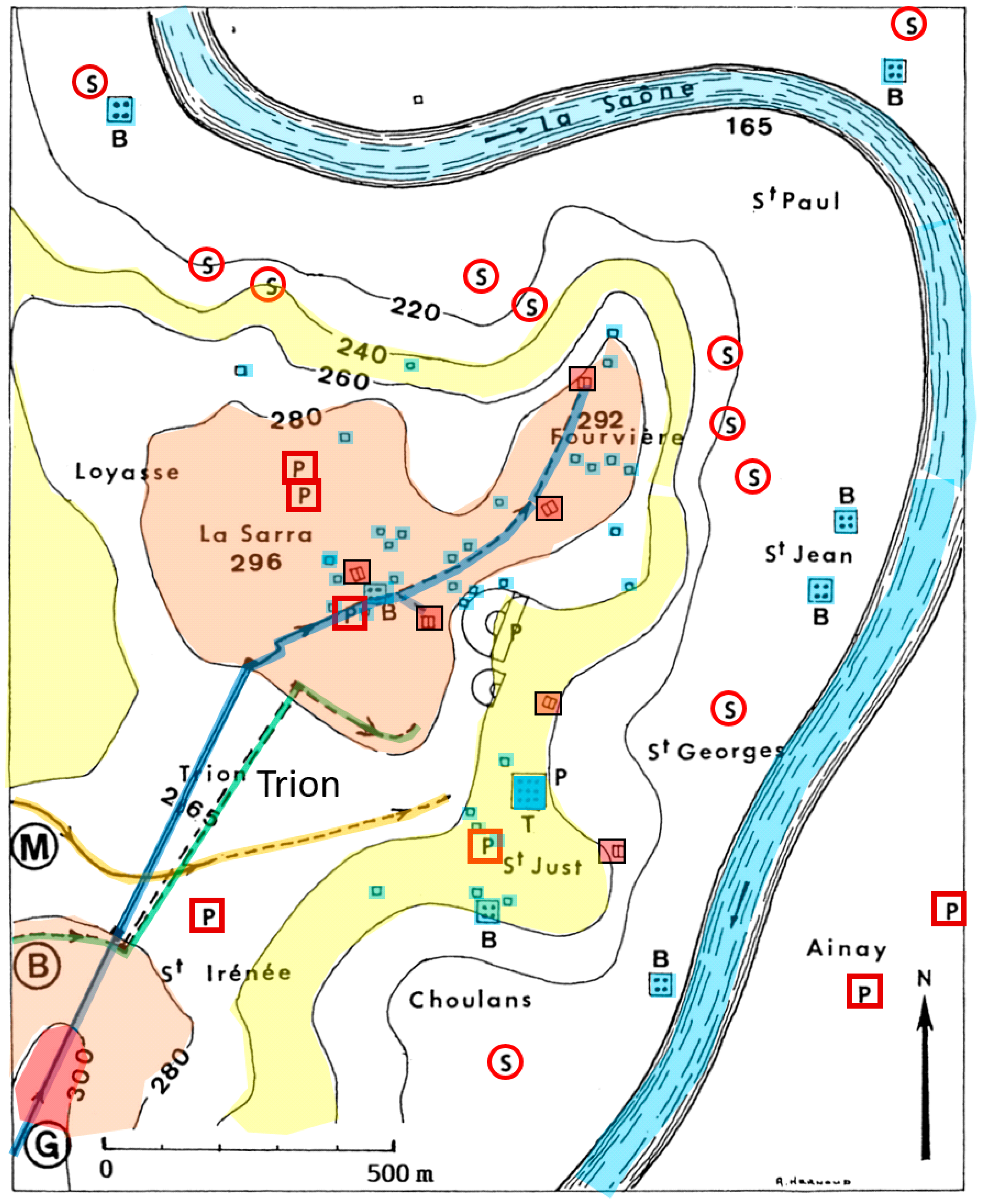
Trion area’s at a level of about 260 m directed toward the Roman theatre and the thermes (see
Figure 4 and
Figure 5).
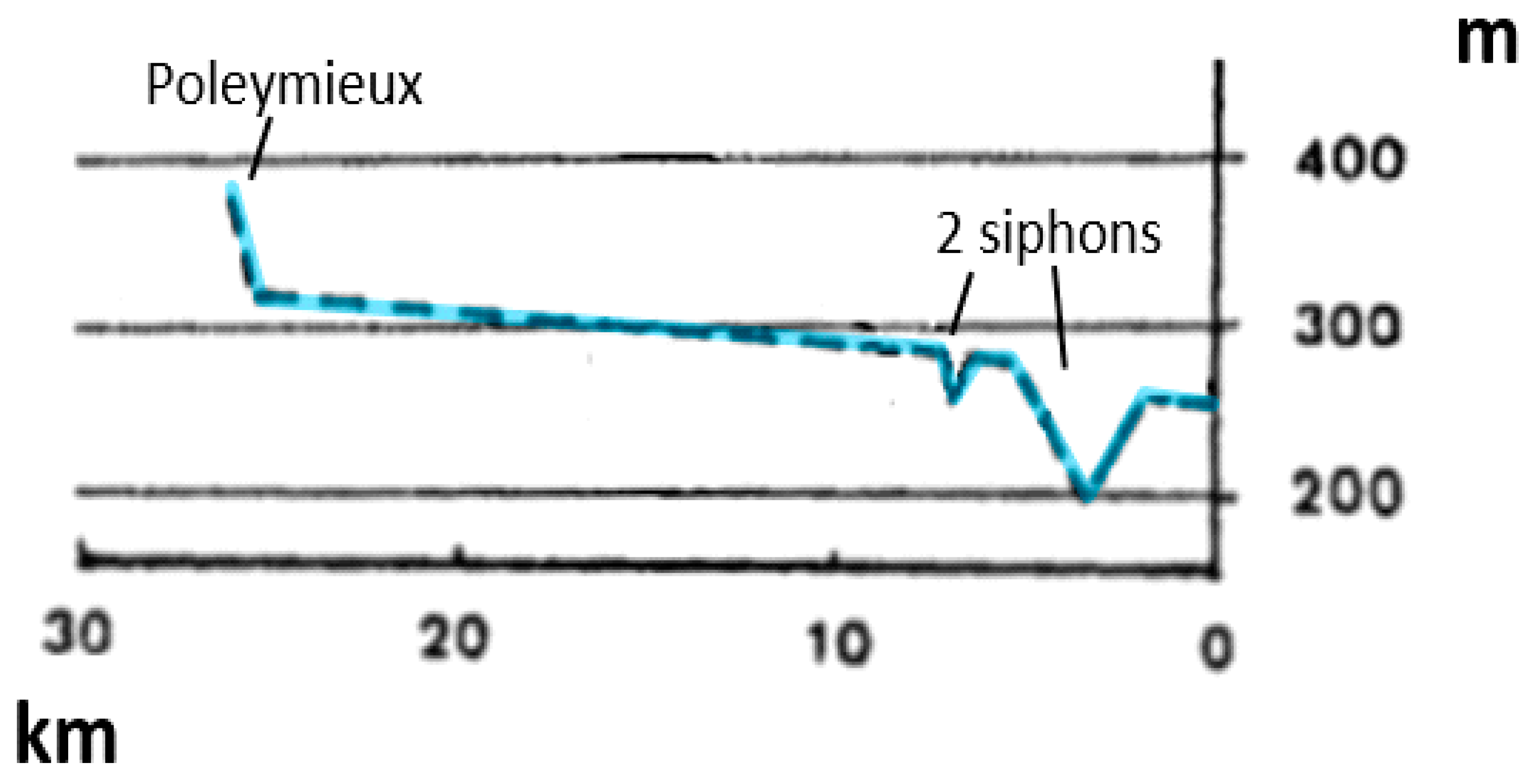
The capacity of the Mont d’Or aqueduct, that is, how much water was transported per day to Fourvière, depends on the dimensions of the channel and its slope, the roughness of the channel walls, and the level of the water running in the channel. The channel’s slope, as depicted in
Figure 18, appears rather constant between the steep section at Poleymieux and the two siphons. The wall roughness of a newly built channel is less than that of an incrusted one, which translates to a different roughness coefficient in calculating formulas. The smaller this coefficient, the faster the water will flow.
Jean Burdy has calculated the capacity in cubic meters per day for the channel 50 cm wide, and for a presumed water level of 30, 40, and 50 cm for a slope of 1.4 m/km with the Bazin formula (see for Bazin and similar formula’s for open channel flow for instance
https://theconstructor.org/fluidmechanics/chezys-and-mannings-formula-in-open-channel-flow/558411/, accessed 1 March 2024). Taking the seasonal water delivery of the springs feeding the aqueduct into account, Burdy estimated an effective capacity of 2000–6000 m
3/day [
7], p. 36–37.
5. The Gier Aqueduct
The aqueduct of Gier, taking its name from the river that provided its waters, was probably constructed under Hadrian (117–138 CE) [
2], p. 28. It is the longest and latest aqueduct bringing water to Lugdunum. Its channel, running from south to north, is 86 km long, including an 11 km section circumventing a complicated valley at Chagnon in the south that was bypassed by means of a siphon (
Figure 19). The Gier channel took its waters from a tributary of the Gier river near Izieux village about 42 km south of Lyon. A low dam is thought to have collected the water, of which no trace has remained due to modern construction for the water provision of nearby St. Chamond. The acidic water entering the Gier channel was free of calcium carbonates, as the supplying area is not karstic but granite. As a result, the Gier channel exceptionally remained without any calcareous incrustations (calcareous incrustations are common in aqueducts and may provide information about the period during which that water flowed, as well as of many other aspects [
11,
12].
Without counting the four siphons, the 86 km Gier channel including the 11 km detour at Chagnon, and ran for 90% in an earth covered trench some 2 m wide and 3–4 m deep that followed the terrain level (
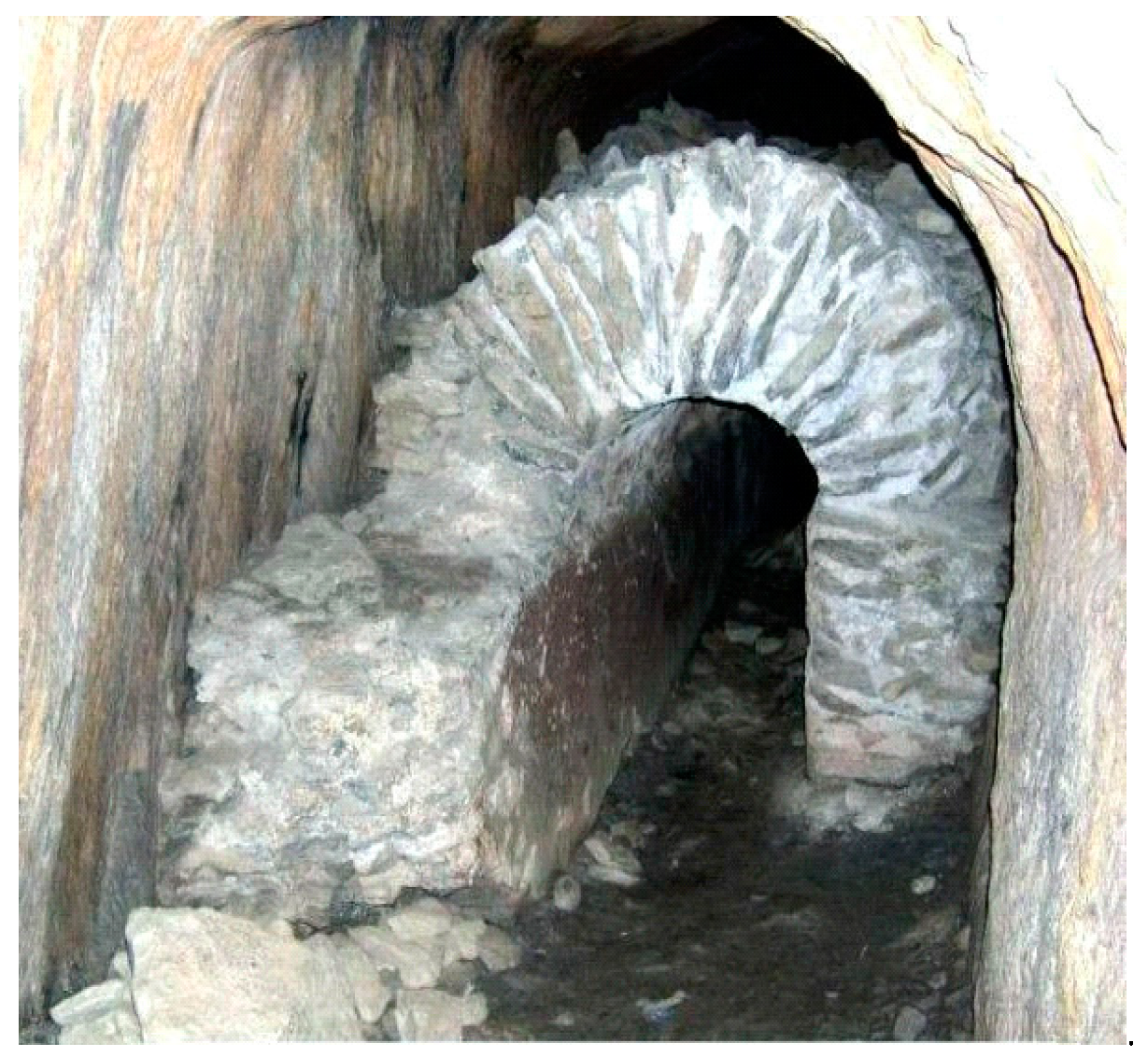
Figure 20). There were 11 tunnels incorporated in the aqueduct, 10 of which have been identified, and 1 being hypothetical near St. Chamond. The tunnel lengths range from 80 m (the so-called
Cave du Curé near Chagnon, (
Figure 21)) to 825 m (near Mornant); the total length for all tunnels is 3.4 km (
Figure 22).
Starting at a level of 405 m, the Gier aqueduct ended on the Fourvière hill at 299.5 m, the only of the four aqueducts that could serve the entire town. The average slope is about 1 m/km, ranging from 0.6 to 1.85, not taking the siphons and the Chagnon detour into account [
9], p, 284. The slope of the Nîmes aqueduct is an extremely low 7 cm/km for 10 km downstream of the Pont du Gard [
13], p. 189.
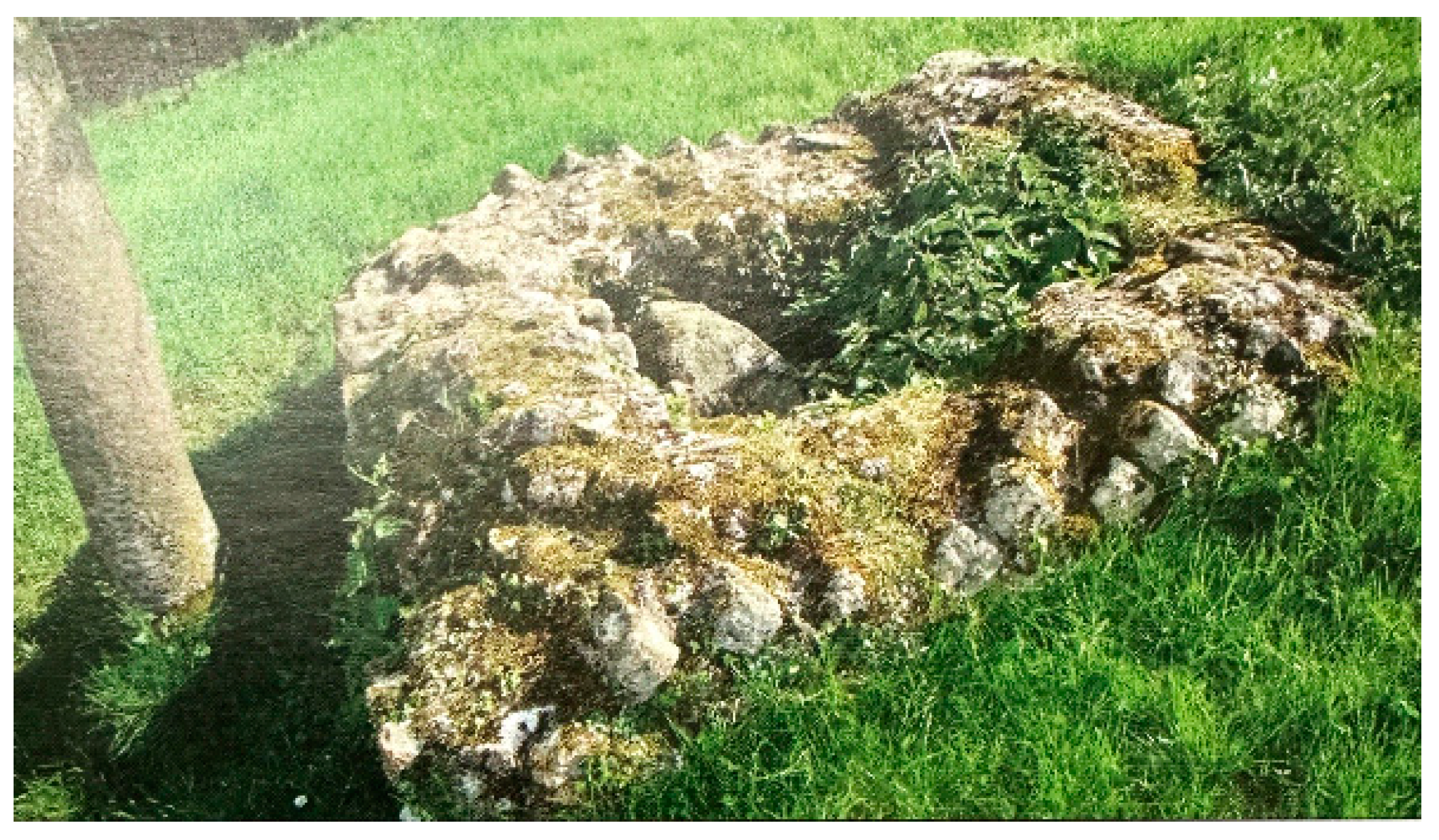
For maintenance, repairs, and cleaning, the Gier channel was accessible from above by means of vertical inspection shafts (french: ‘
regards’, german: ‘Einstiegschacht’) of rectangular shape (2 × 2½ feet to 3 × 3 feet), the entrance covered by thick stone slabs (
Figure 23). A total of 91 of these inspections shafts have been found, also connecting to tunnels, having a regular interdistance of 77 m which would count, if systematically installed, to up to 1000
regards for the entire aqueduct [
2], p. 36.
The Gier aqueduct incorporated over 30 bridges and some 10 channel sections on arches and walls, of which important remains survive. At the ‘
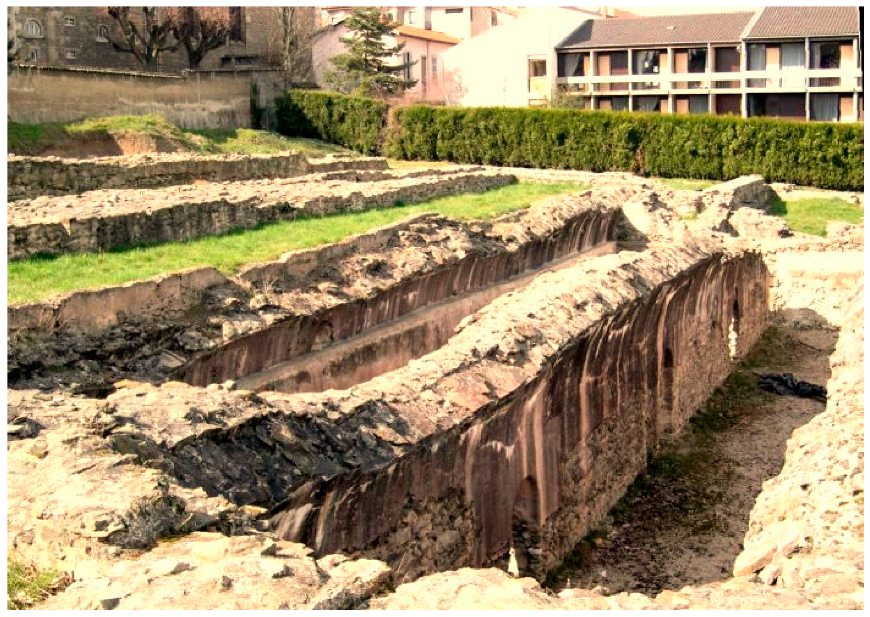
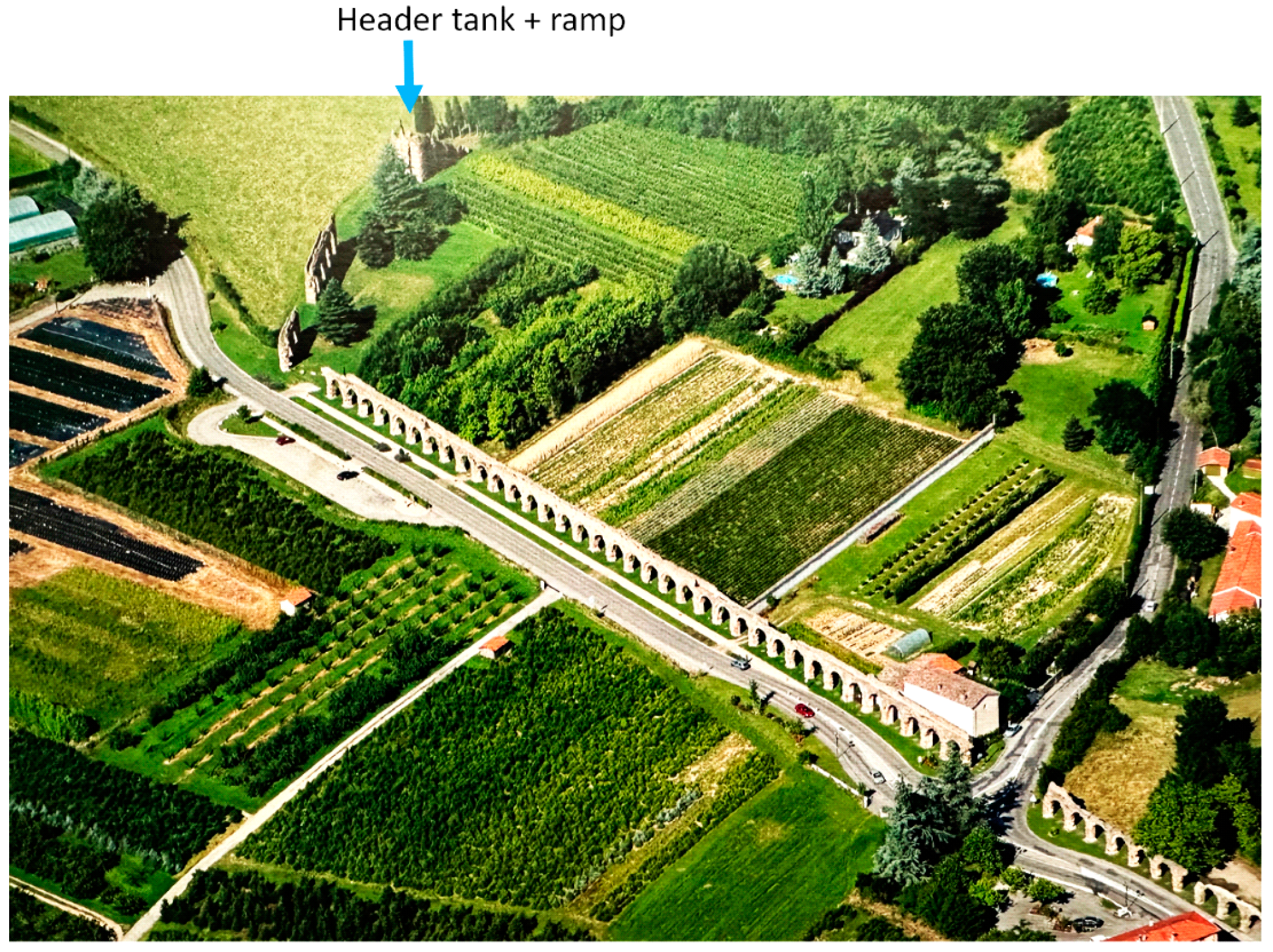
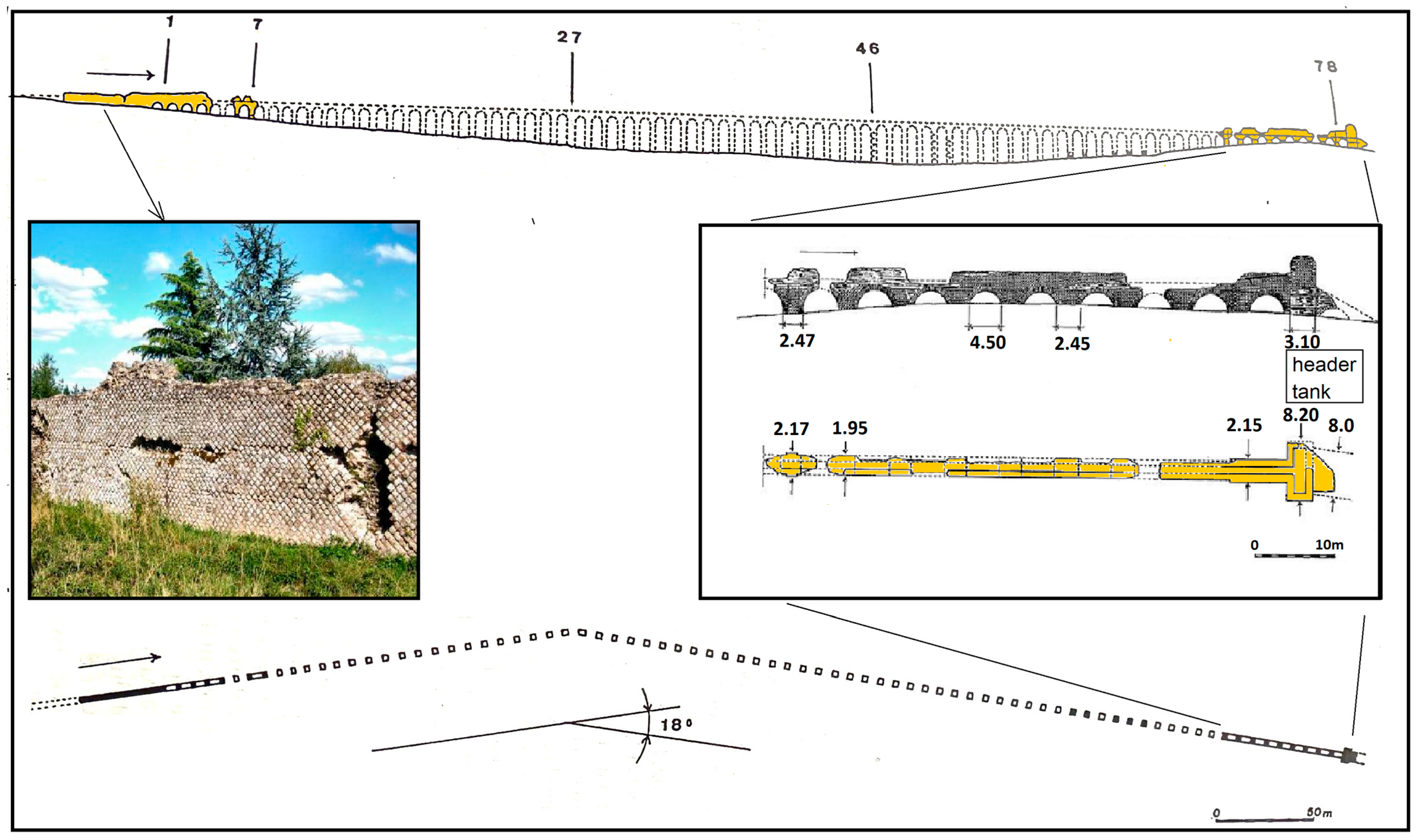
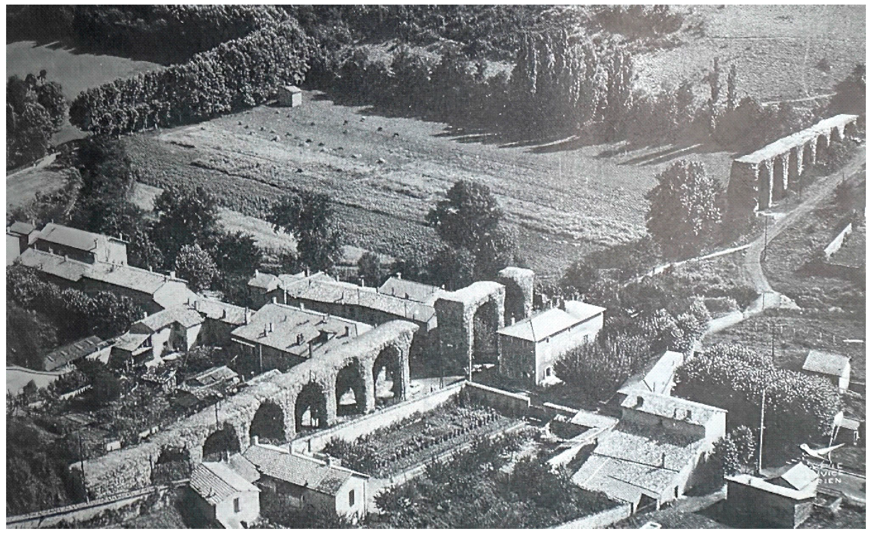
Plat de l’Air’ near Chaponost, the channel was carried on an impressive row of 92 well preserved arches that run along the local traffic road (
Figure 24). Directed towards the north-west it turns eastwards, ending at the header tank of the siphon that crossed the valley of the Yzeron river.
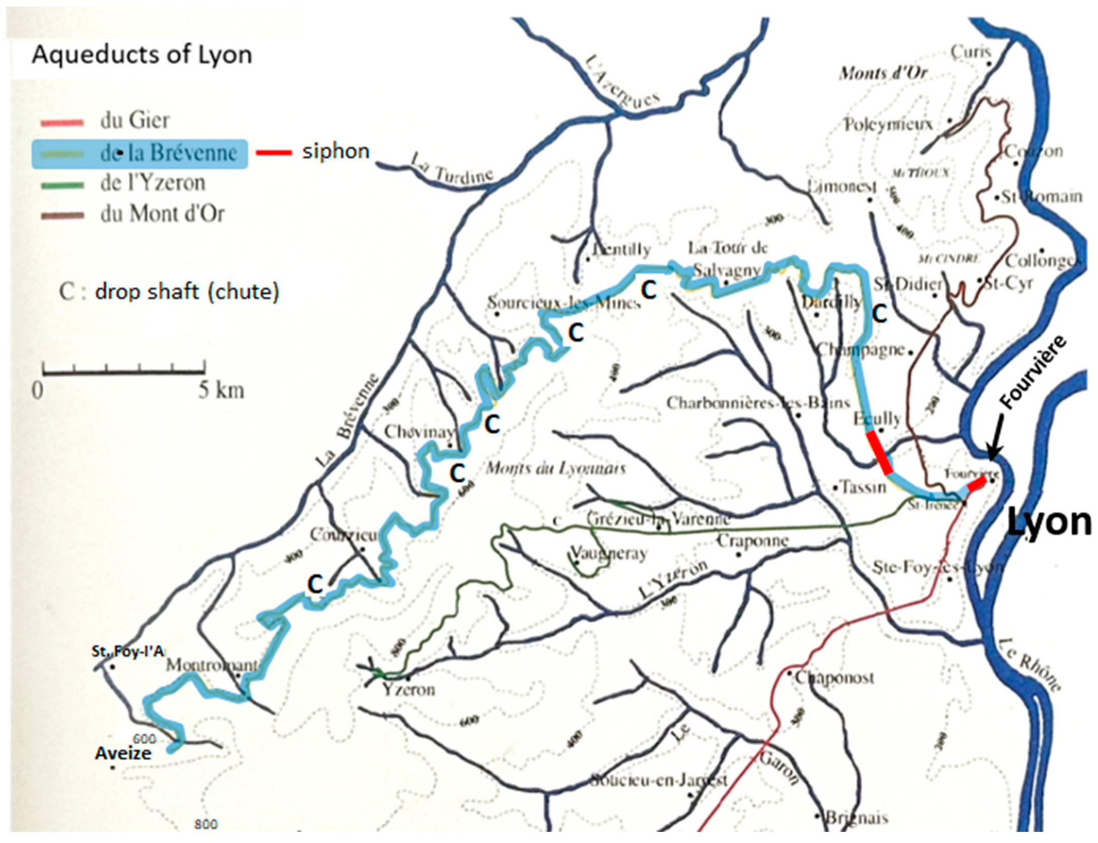
Figure 19.
The aqueducts of Lyon, with the Gier aqueduct highlighted in blue, its four siphons in red. The Gier aqueduct took its waters from a contributary of the Gier river near Izieux village in the south where a low barrage is thought to have been installed, of which no trace remains because of the installation of water provision works for St. Chamond village 3 km to the north [
14], p. 64, adapted.
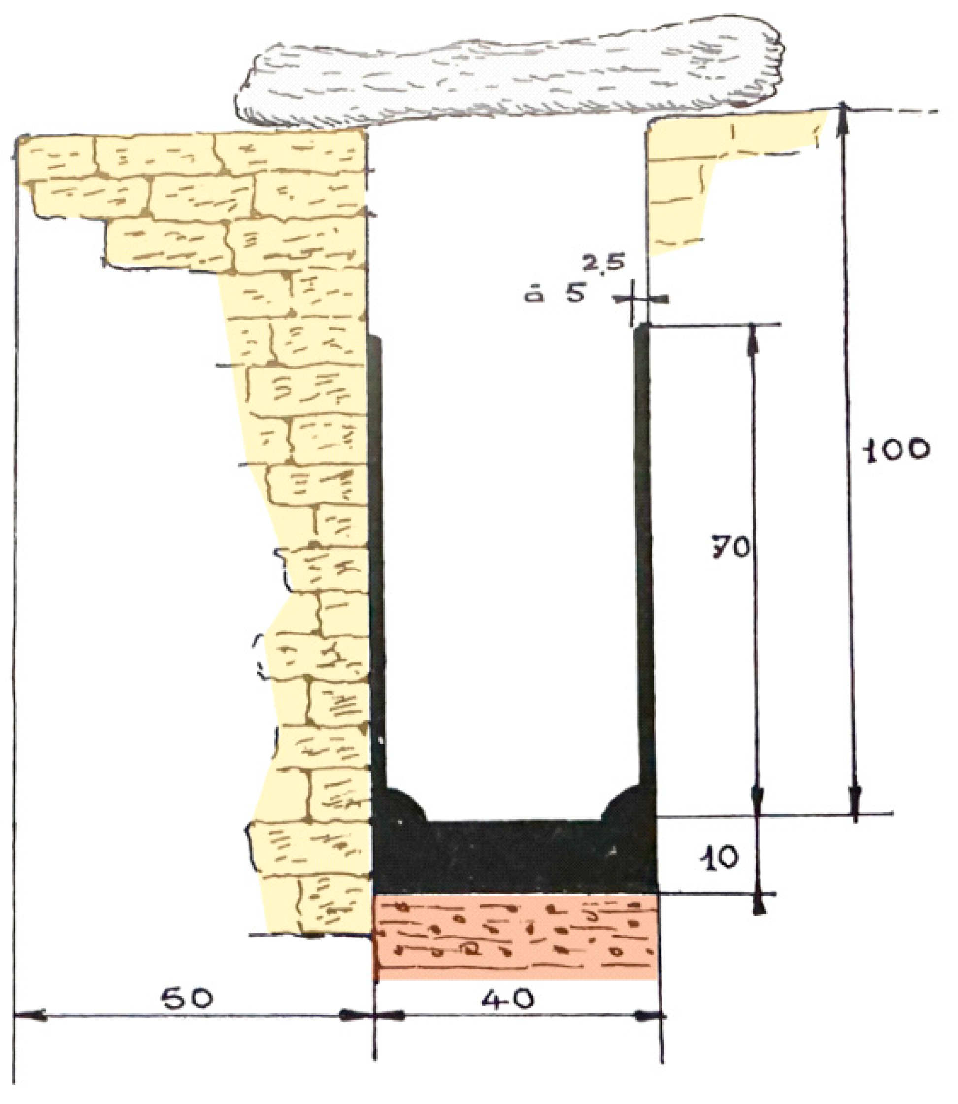
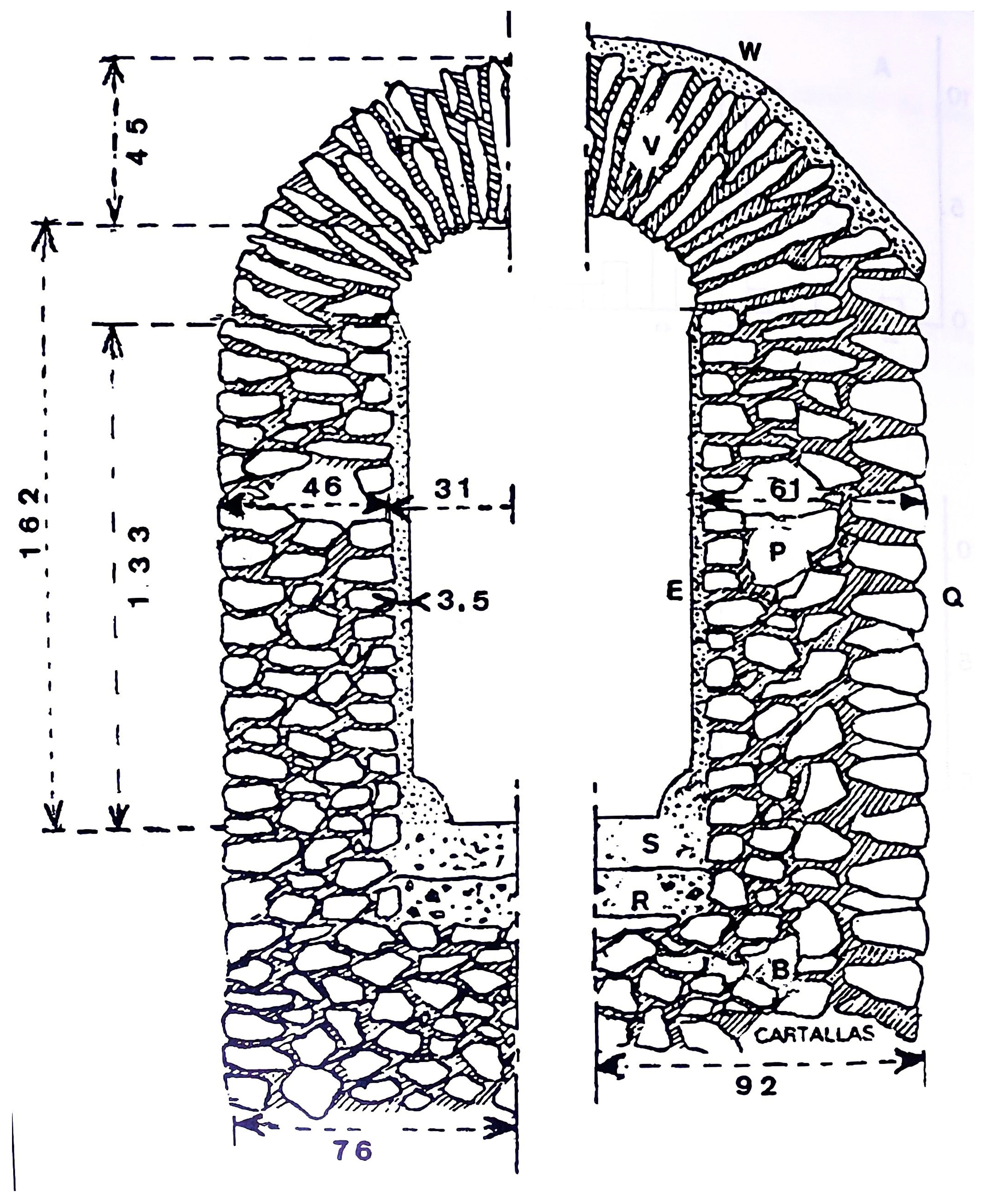
Figure 20.
Gier aqueduct, channel construction. Left: trenched channel, right: channel on or above ground level. Channel width 55 cm, height to top of vault on the inside 162 cm. The walls of the channel exposed to atmosphere are with 61 cm, 15 cm thicker than of the trenched channel, while its barrel vault is covered on the outside with a water tight cement, as are the floor and inside walls for both types of channel [
9], p. 190.
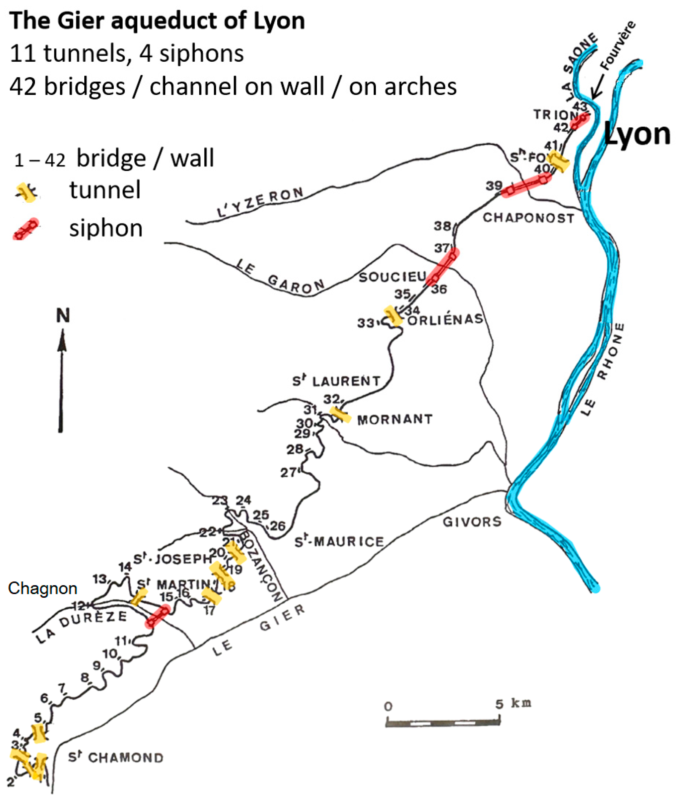
Figure 22.
Gier aqueduct. Tunnels, bridges, and channels on wall or on arches [
9], p. 226, adapted.
Figure 22.
Gier aqueduct. Tunnels, bridges, and channels on wall or on arches [
9], p. 226, adapted.
Figure 23.
Inspection shaft near Mornant, covering slab broken [
2], p. 36.
Figure 23.
Inspection shaft near Mornant, covering slab broken [
2], p. 36.
Figure 24.
Gier aqueduct, Plat de l’Air–Chaponost. Channel on arches 15 m high over a distance of 600 m. The piers are 1.85 m square, interspace 4 m [
2], p. 25; [
9], p. 154. The header tank of the Yzeron siphon where the row of arches ends is visible in the left top of the photo. The arches have undergone restoration in 2022–2024.
7. The Durèze Siphon
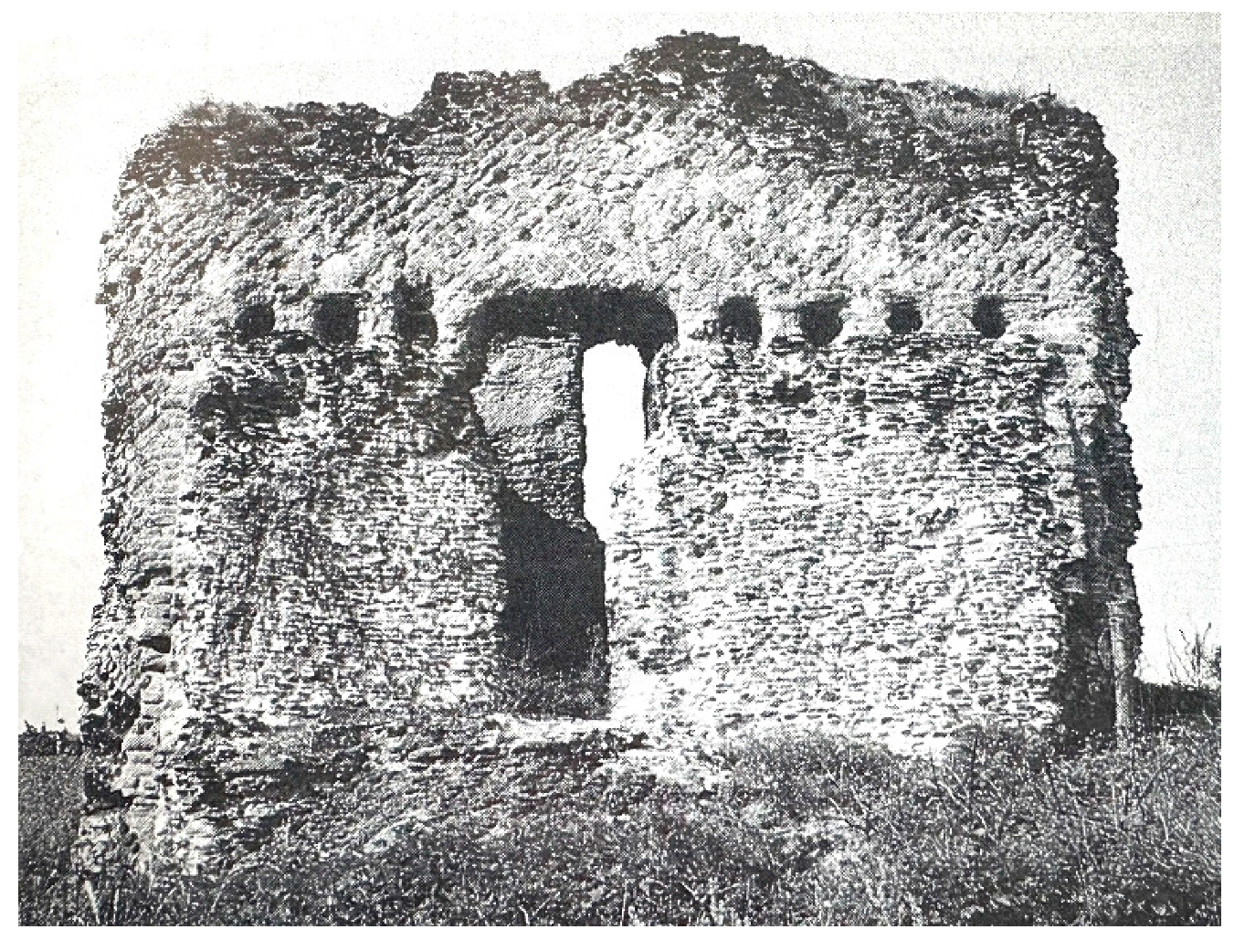
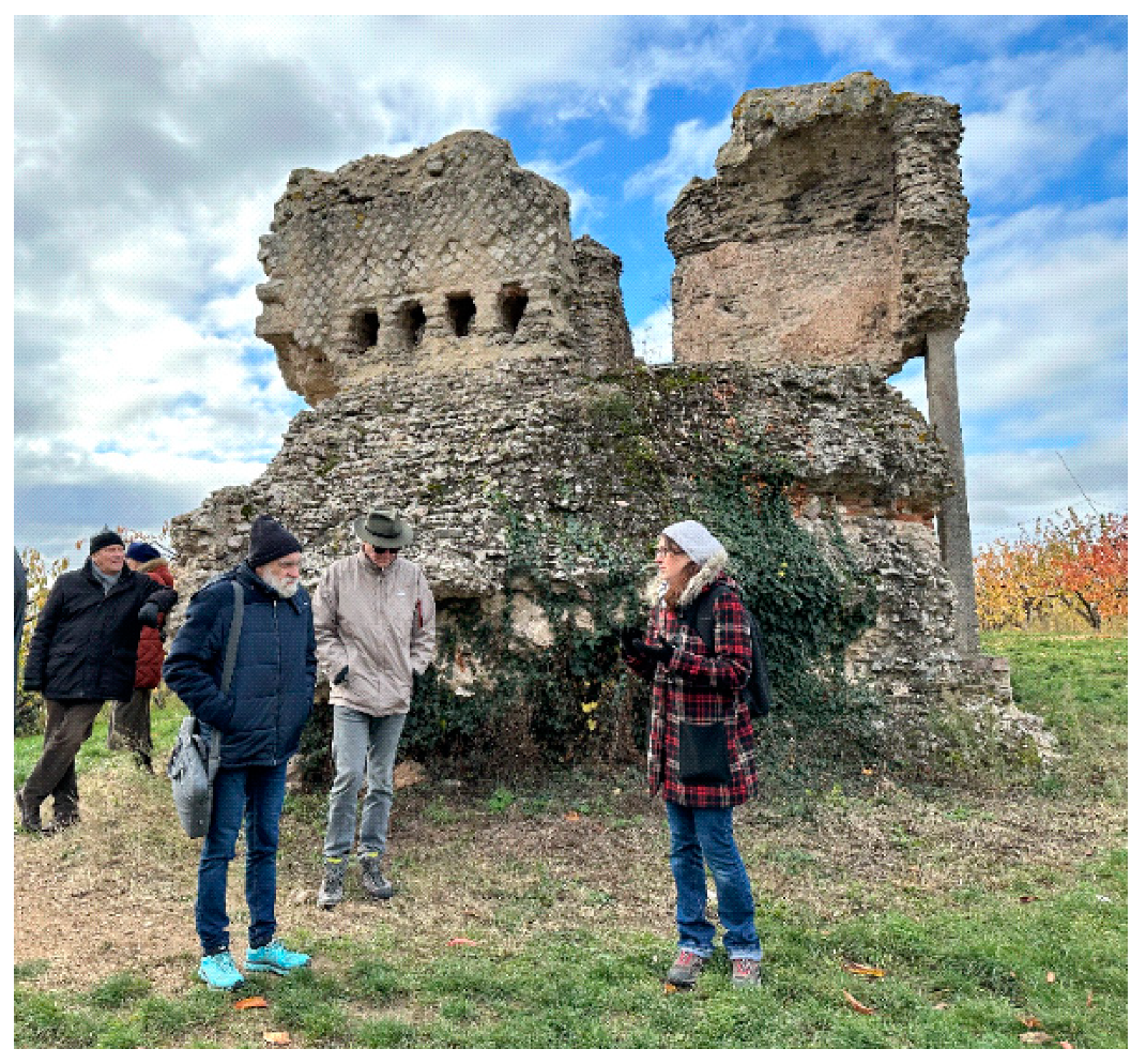
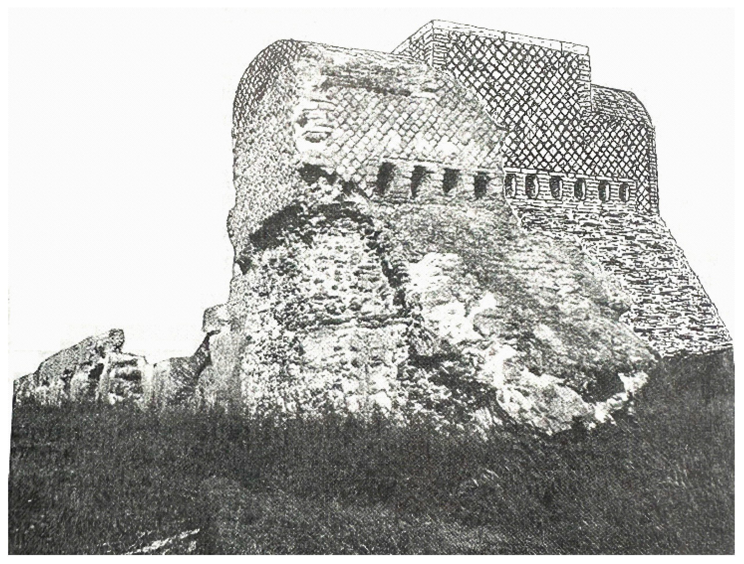
Of the siphon crossing the Durèze river near Genilac, the header tank has been well preserved, but no trace remains of the receiving tank (
Figure 25). On the valley side, the header tank shows openings for the lead conduits going down, from which the size of the conduits may be estimated at about 23–25 cm outer diameter. A gap from destruction in this side is suggestive for another three openings, a total of ten, of which according to researchers like Germain de Montauzan, one or two openings were obstructed (
Figure 26).
The back side of the 8.3 × 4.15 m construction shows the opening for the channel that provided the 6.4 × 2.25 m reservoir from which the lead conduits took water. The down-going rampart is destroyed over its greater part.
The question is, of course, why is there a siphon at this point bypassing the 11 km channel that circumvents the complicated valley at Chagnon? Were both constructed simultaneously? This 11 km channel has the moderate slope of 0.5 m/km or 5 cm per 100 m, not an uncommon gradient for aqueducts which would translate into a somewhat reduced water velocity combined with a high water level in the 133 cm high channel, but not necessarily resulting in an insufficient capacity (the channel of the Nîmes aqueduct had a slope of 7 cm/km for 10 km downstream of the Pont du Gard (Hodge 1992, p. 190)). Because of the acidic water of the Gier springs, no calcareous incrustations were left on the channel walls, so we do not know the historic water level in the channel (Burdy calculated from formulas the theoretical capacity of the Gier Aqueduct for water levels of 30 cm to 70 cm in the 133 cm high channel, resulting in an average capacity of 12,000 m3 per day (for which the water height in the channel at Chagnon would have been some 70 cm (Burdy 2017, p. 48; Burdy 1993, pp. 287–288)). The capacity of the siphon must be deemed sufficient as well (see Burdy 1996, 293–294. Burdy states that further investigations might resolve the issue whether the 11 km circumvention or the Durèze siphon was installed first).
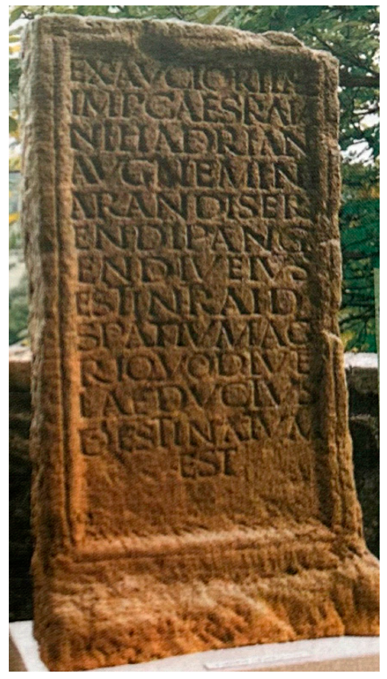
On 27 April 1887, an interesting find was done during new road works close to Chagnon, when a stone slab 158 × 62 × 20 cm was found carrying an inscription, since then called ‘
la Pierre de Chagnon’ (
Figure 27). The inscription reads ‘By the order of Caesar Traianus Hadrianus Augustus no person is allowed to work, sow, or plant in the space of the terrain that is destined for the protection of the aqueduct’. Remarkably, on 10 September 1996, a similar inscription stone was found, along the channel at the village of St. Joseph, broken in four pieces and incomplete, but shown to be inscribed with the same text (
Figure 28).
The inscription reminds of the text of Frontinus, in 97 CE Curator Aquarum of Rome, who refers to a decree of the Senate stating ‘… that around the springs, the arches, and the walls on both sides a space must be left free of 15 feet, and that around underground channels and roofed channels inside the town and in adjacent built-up area outside the town on both sides a space of five feet must left free …’ subject to a penalty of 10,000 sesterties. No such recommendation about is mentioned on the stones of Chagnon and St. Joseph.
Clearly, the Chagnon detour and the continuing channel at St. Joseph were similarly treated, and they must have been equally important. So one may suppose that the detour at Chagnon was designed as such from the start. What then about the Durèze siphon? Designing a siphon and constructing it required special skills of both engineers and sufficient building knowledge, not the least because of the many lead conduits that had to be soldered together on the spot. Furthermore, an aqueduct was not constructed from source to city, but in stretches simultaneously in order to reduce the construction time needed (as for the aqueduct of Cologne [
15], pp. 58–59. Once the overall design was decided upon, specialized teams would be put to the task of constructing the siphons on locations as planned, while the channel was to be connected to the siphon once the ‘channel team’ had made it to the header tank. The precipitously steep and 100 m deep Durèze valley not only challenged the siphon team, reducing the static pressure down in the valley by almost 2 bar with the 19 m high siphon bridge, but during operation, the siphon would be subject to pressure surges endangering the integrity of the siphon at start up, as well as when functioning because of air in the conduit and air entrained at the header tank (see for problems in operating siphons [
1], pp. 47–52. Moreover, the precipitous slope going down, and to a lesser degree, going up and the considerable weight of the lead conduits may have caused the pipes to sag down and destroy the integrity of the soldered pipes even for a try-out procedure. This may have led the designers to proceed from the very start with the Chagnon detour channel and connect it to the channel at the receiving tank direction at St. Joseph. The Durèze siphon may have been built first, but bypassed as soon as severe problems of its functioning became apparent.
9. The Yzeron Siphon
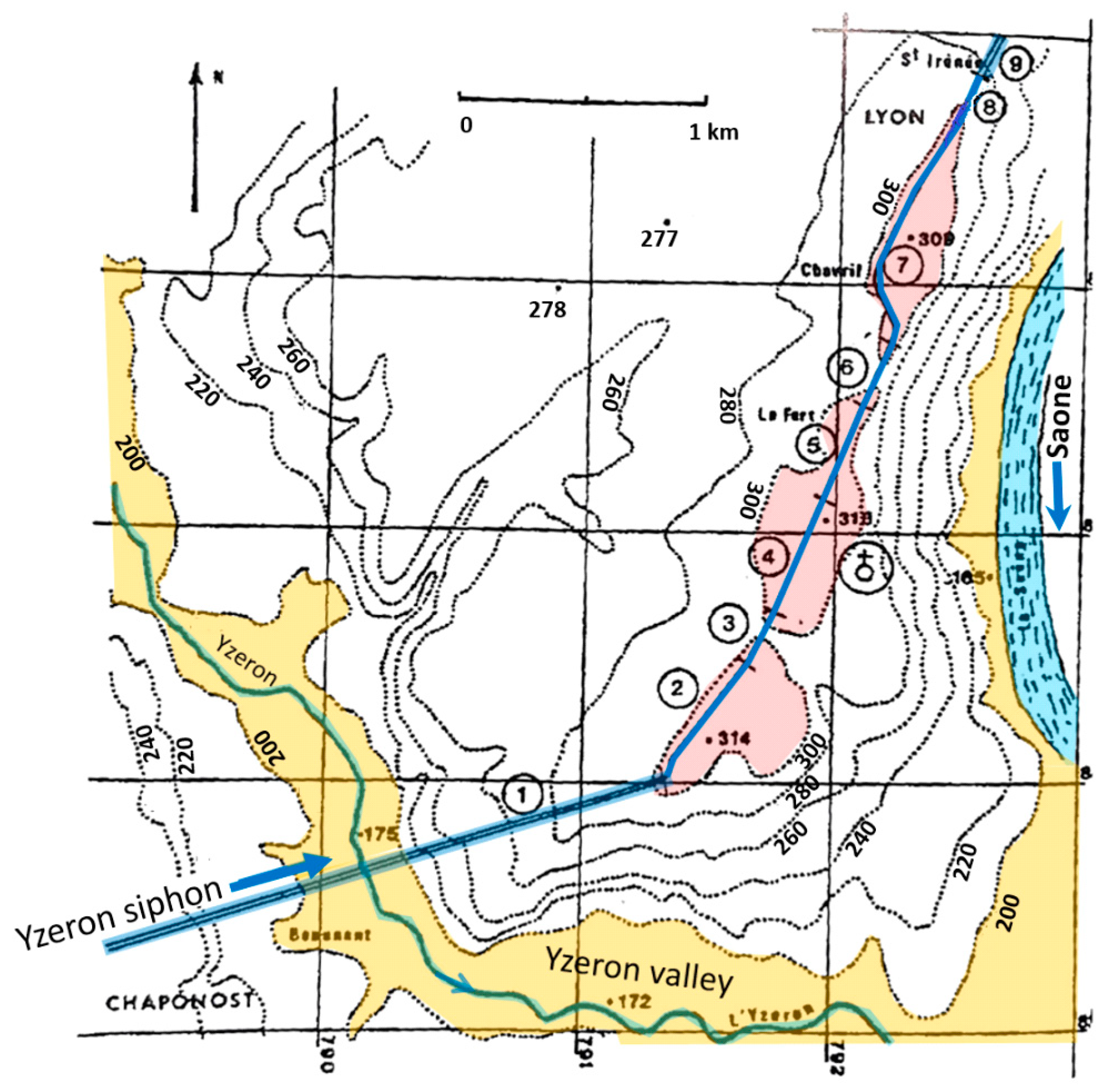
From the Garon receiving tank onwards, the channel crossed the undulating plateau of Chaponost in a northerly direction, both on arches and walls as well as underground for several hundred meters at a time. After some 4.5 km, the flat plain of
Plat de l’Air was crossed on arches up to 15 m high until the channel reached the edge of the valley of the Yzeron river (see
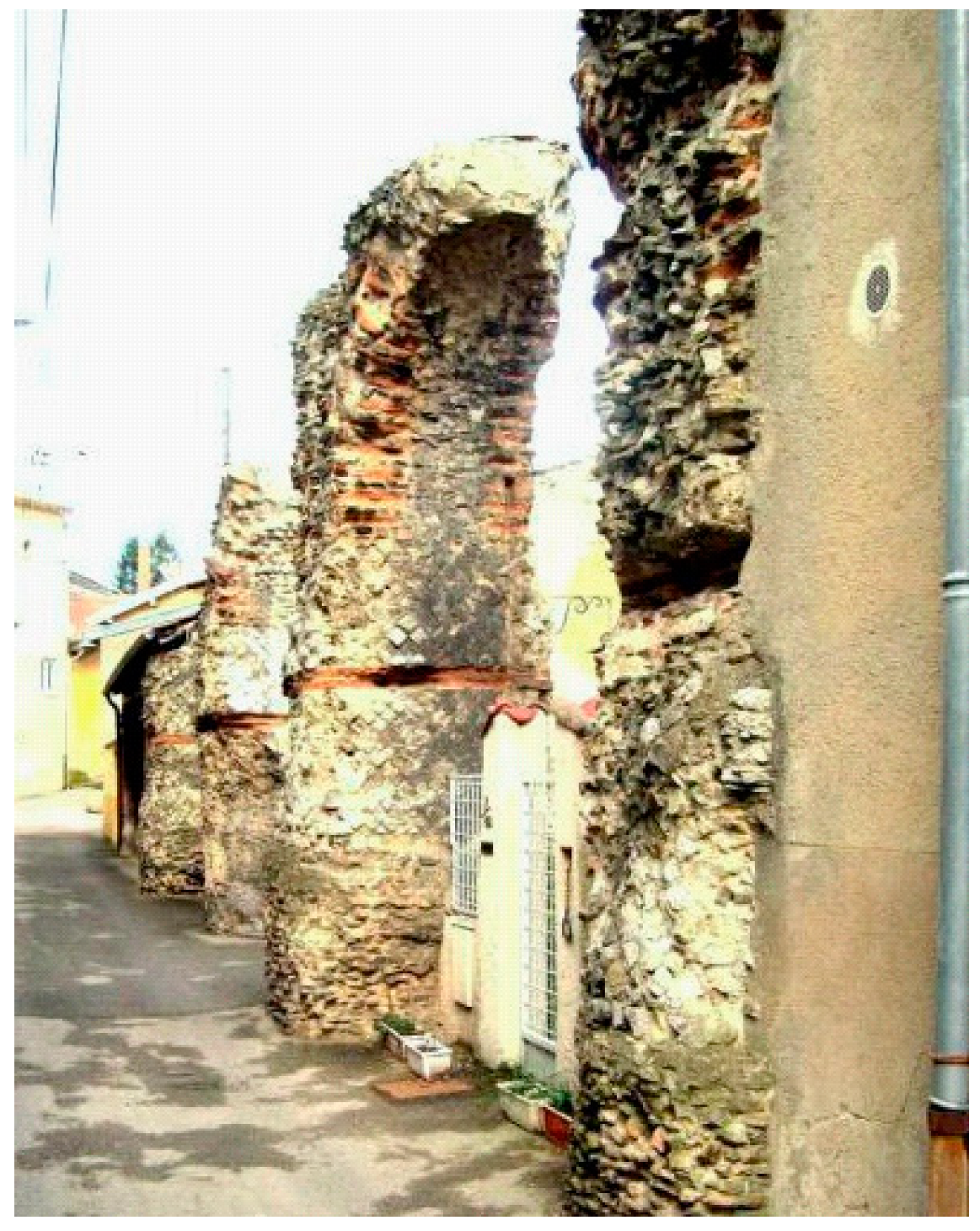
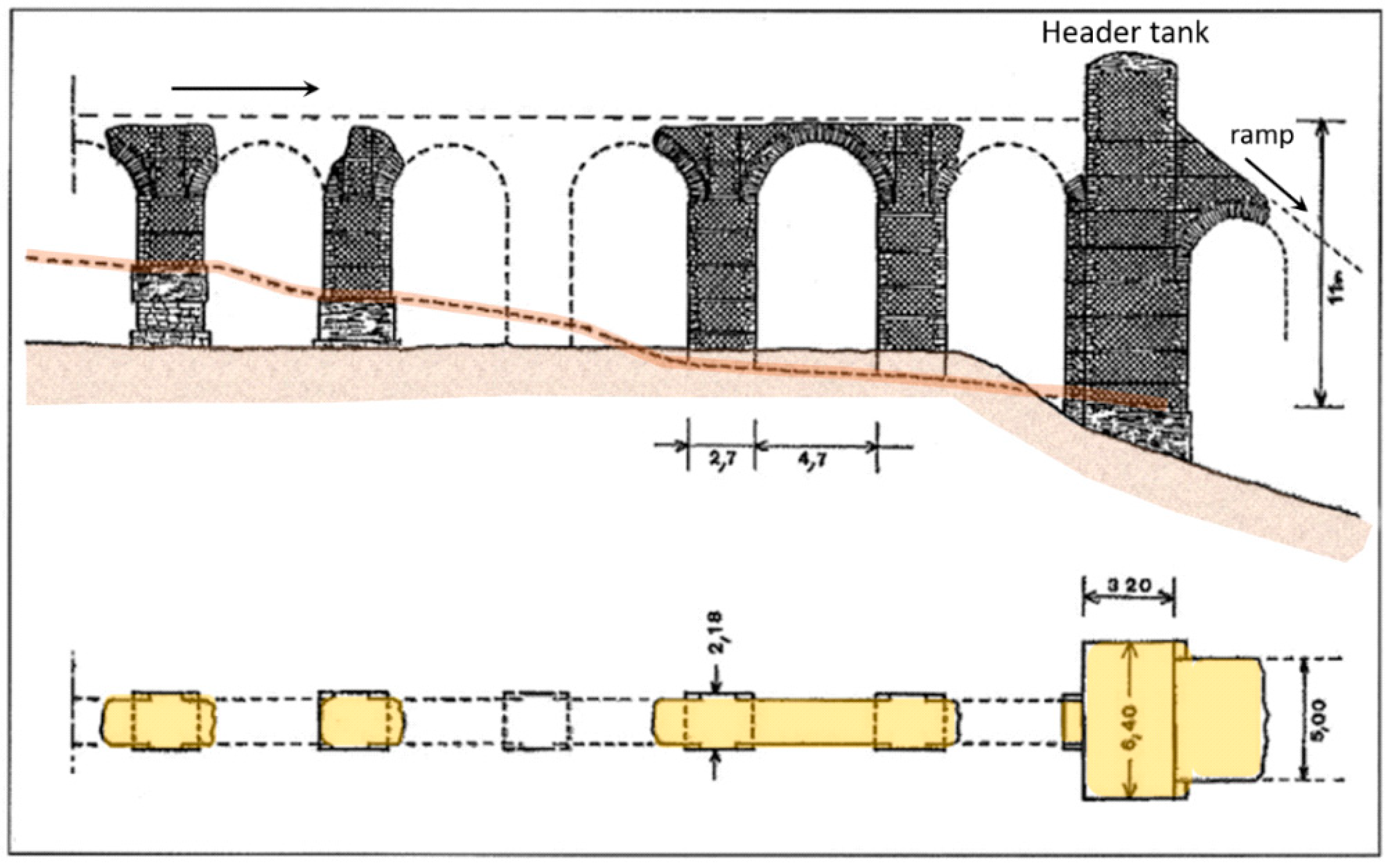
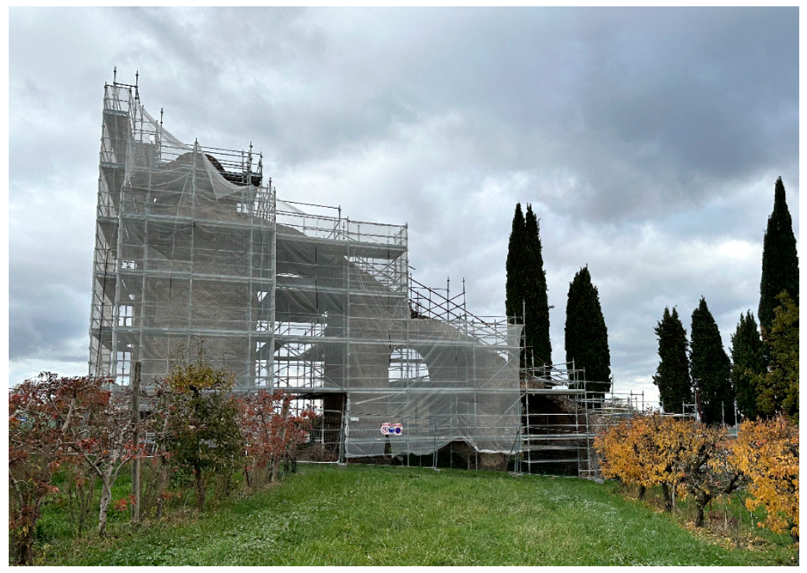
Figure 24 above). The channel on the row of over 90 arches terminates at the header tank situated 10.5 m above ground at a level of 313.7 m, with the start of a siphon with 11 parallel conduits crossing the 140 m deep and 3 km wide valley of the Yzeron river. In 2023, the arches plus channel and header tank were subject to restoration (
Figure 36 and
Figure 37).
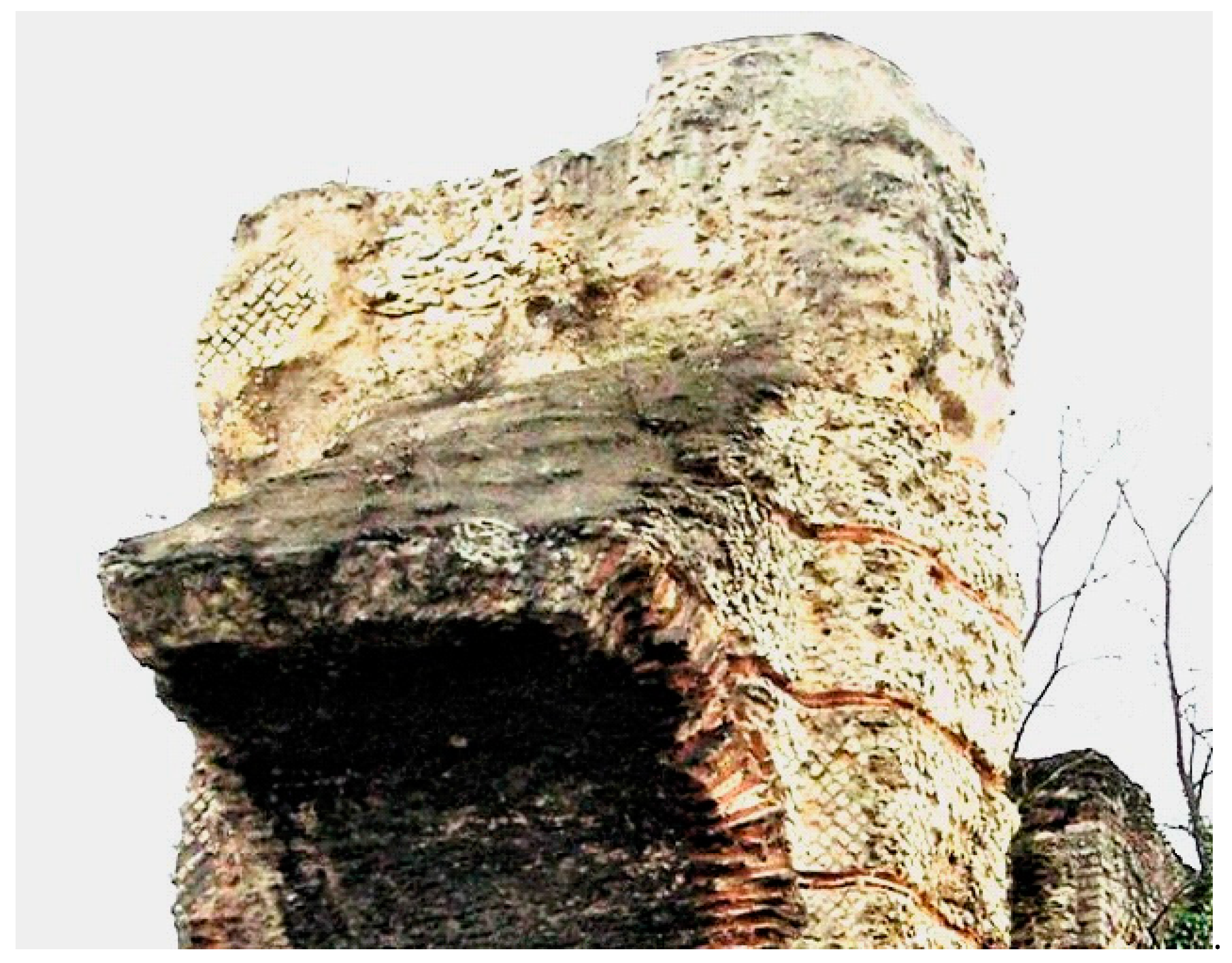
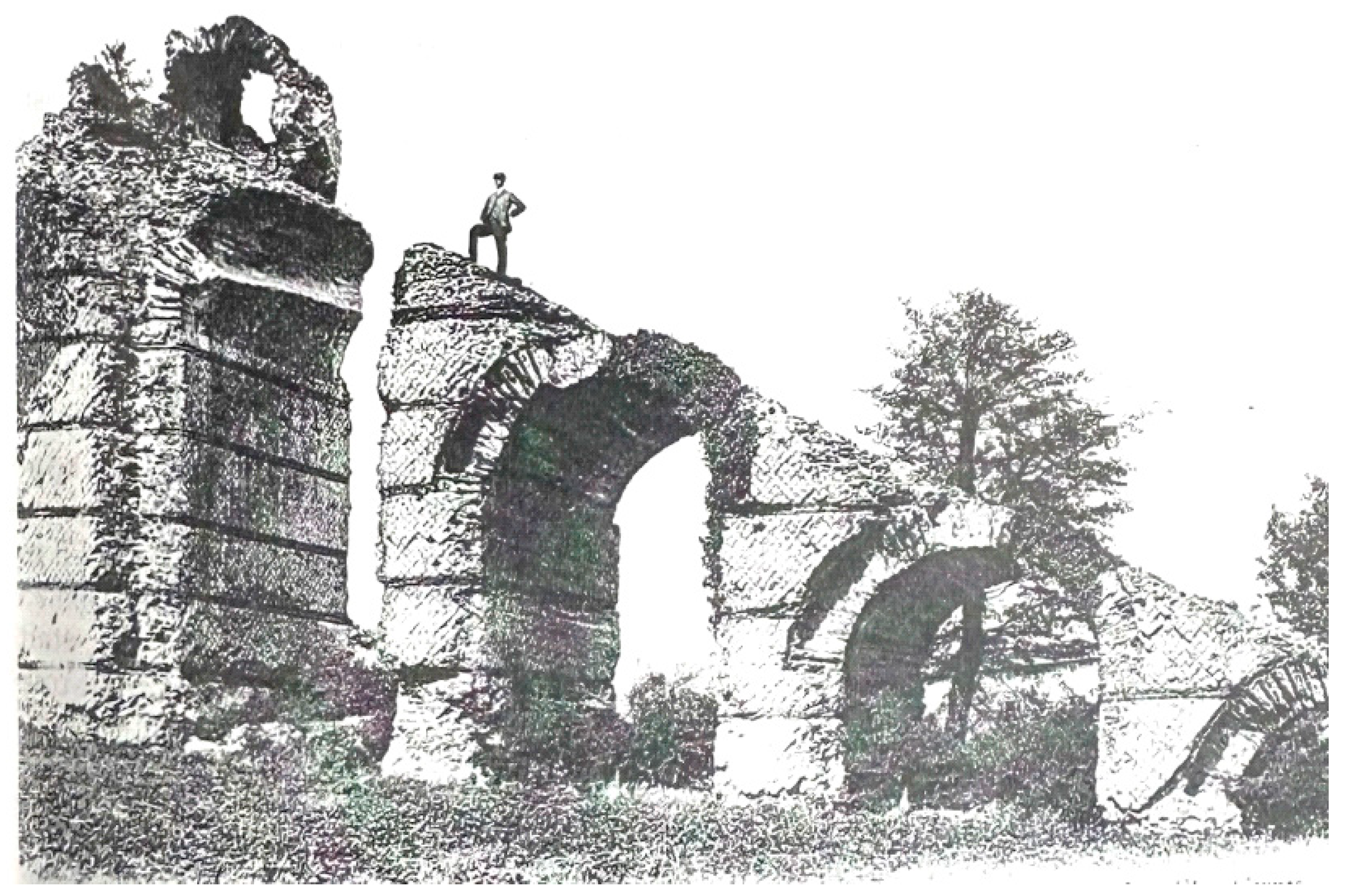
The header tank and ramp were in worse condition a century ago, but now the broken upper arch of the descending ramp undergoing had repairs in the 1930s (
Figure 38 and
Figure 39).
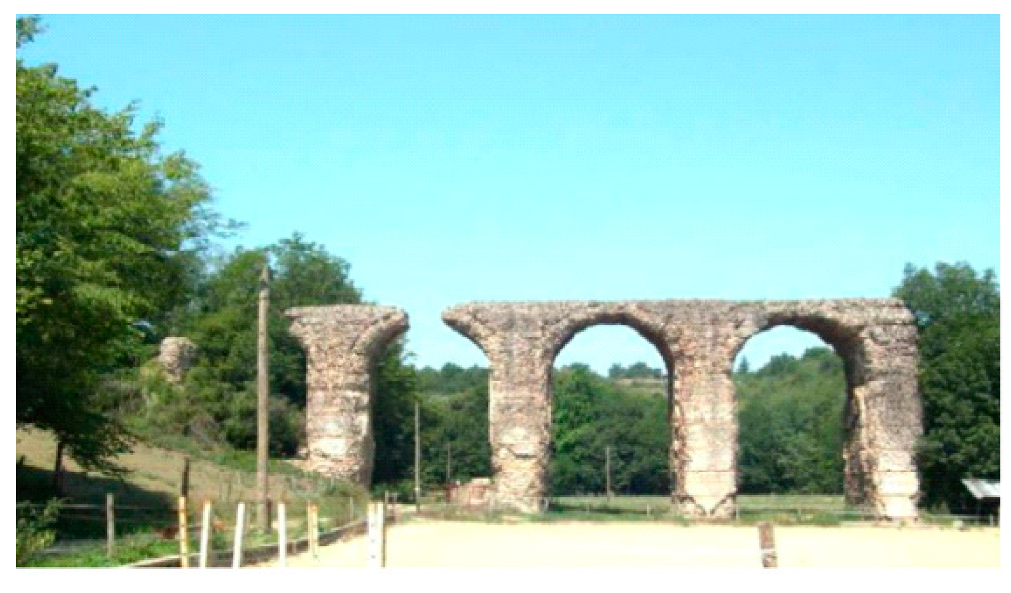
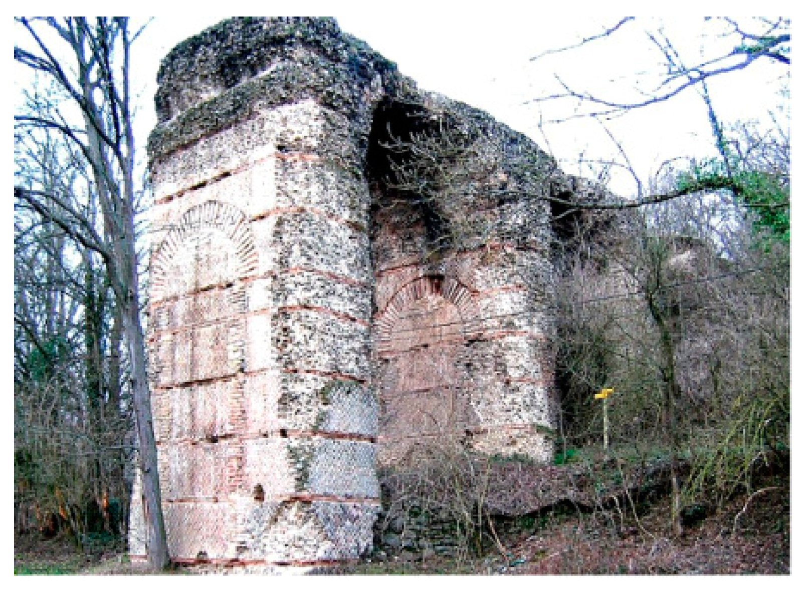
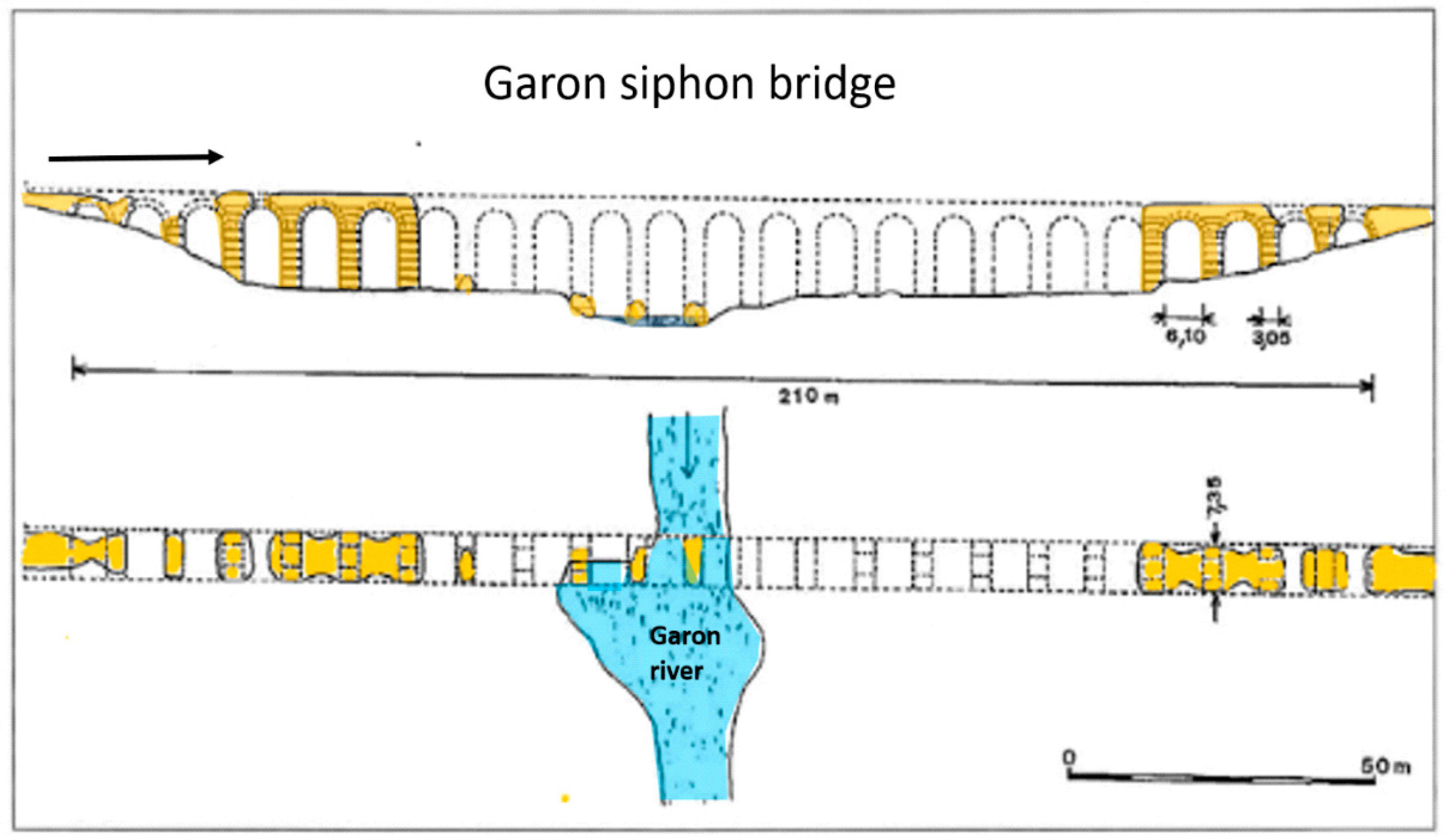
The 11 lead pipes went down the valley side towards the Yzeron river that was crossed by a 270 m long, 7.35 m wide, and 18 m high ‘siphon bridge’ called
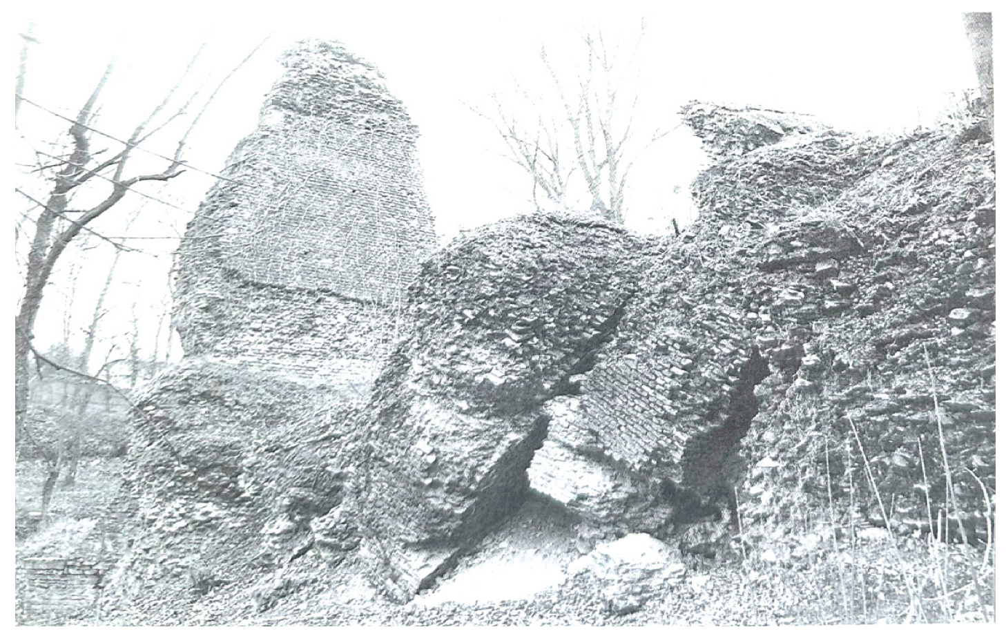
le Pont de Beaunant. The bridge counted 30 arches, of which 15 still stand, 7 on the right side and 8 on the left side of the river bed. In 1875, the bridge was classified as
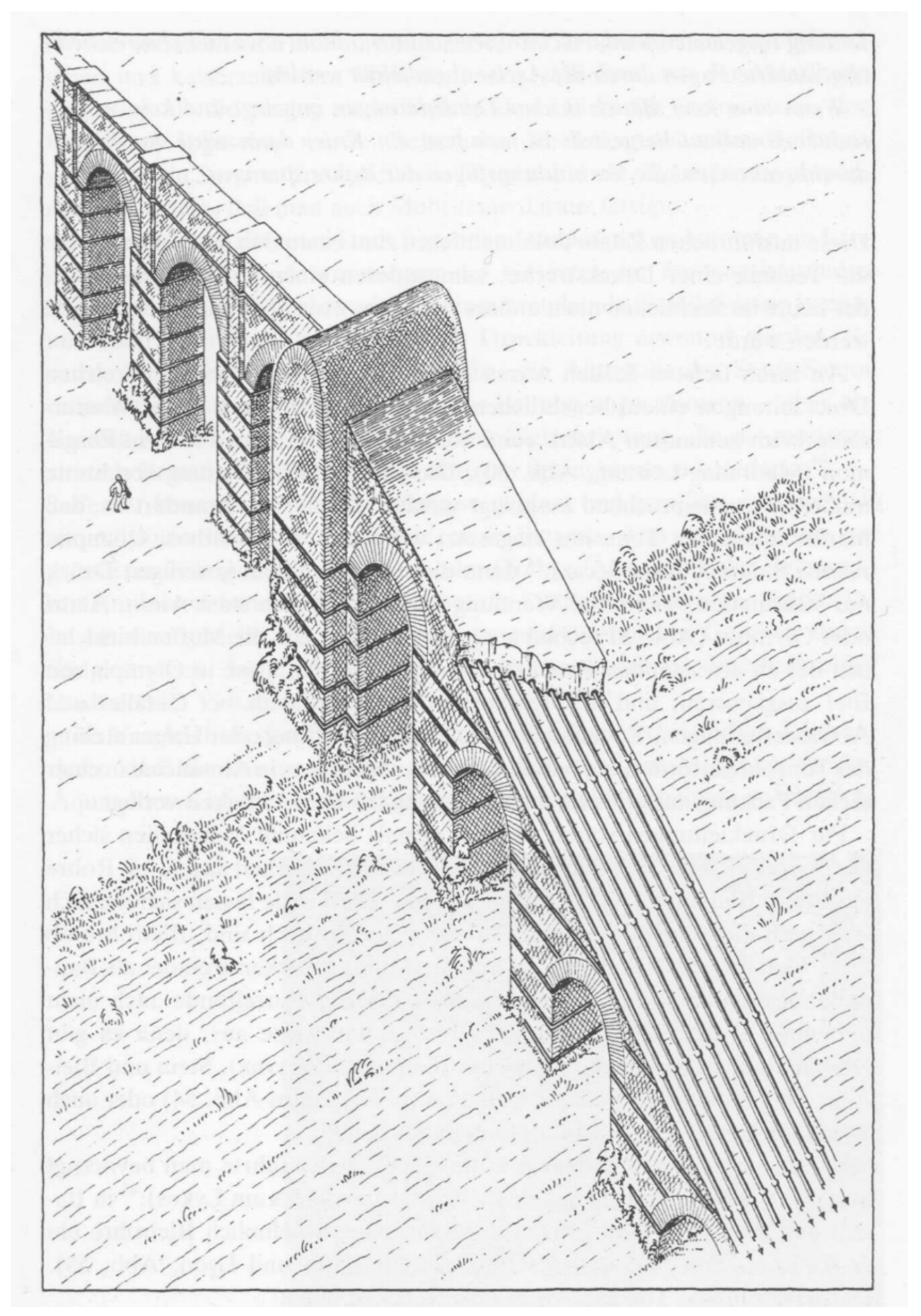
Monument Historique, which, however, did not prevent the construction of a road passing it at square angles, and of several buildings blocking an open view. The 7.35 × 3.05 m piers were built with an arched opening 3.05 m wide in the 7.35 m width that for the largest piers were filled up again soon after the construction to prevent collapse, a row of five and one of three piers with unfilled openings presenting a corridor-like view (
Figure 40 and
Figure 41).
In 1973, some remains were found of the receiving tank’s foundation, measuring 6.75 × 1.80 m, at a level of 305.75 m, including a short section of the departing aqueduct channel 61 cm wide (
Figure 42). The remains are no longer visible.
From the receiving tank, the channel of the Gier aqueduct ran in a northerly direction along the steep 100 m high edge of the Saone river on the highest 300+ m levels of the
Plateau Lyonnais, alternatingly on arches, a bridge, walls, through tunnels, and buried segments (
Figure 43 and
Figure 44). In this built-up area of Lyon, remains of piers are to be seen on some streets. The channel reaches about 3 km to the St. Irénée city quarter, the location of the header tank of the fourth siphon of the Gier aqueduct, and the Trion siphon.
Towards the north from
St. Irénée (top of
Figure 43), the terrain descends to the depression of
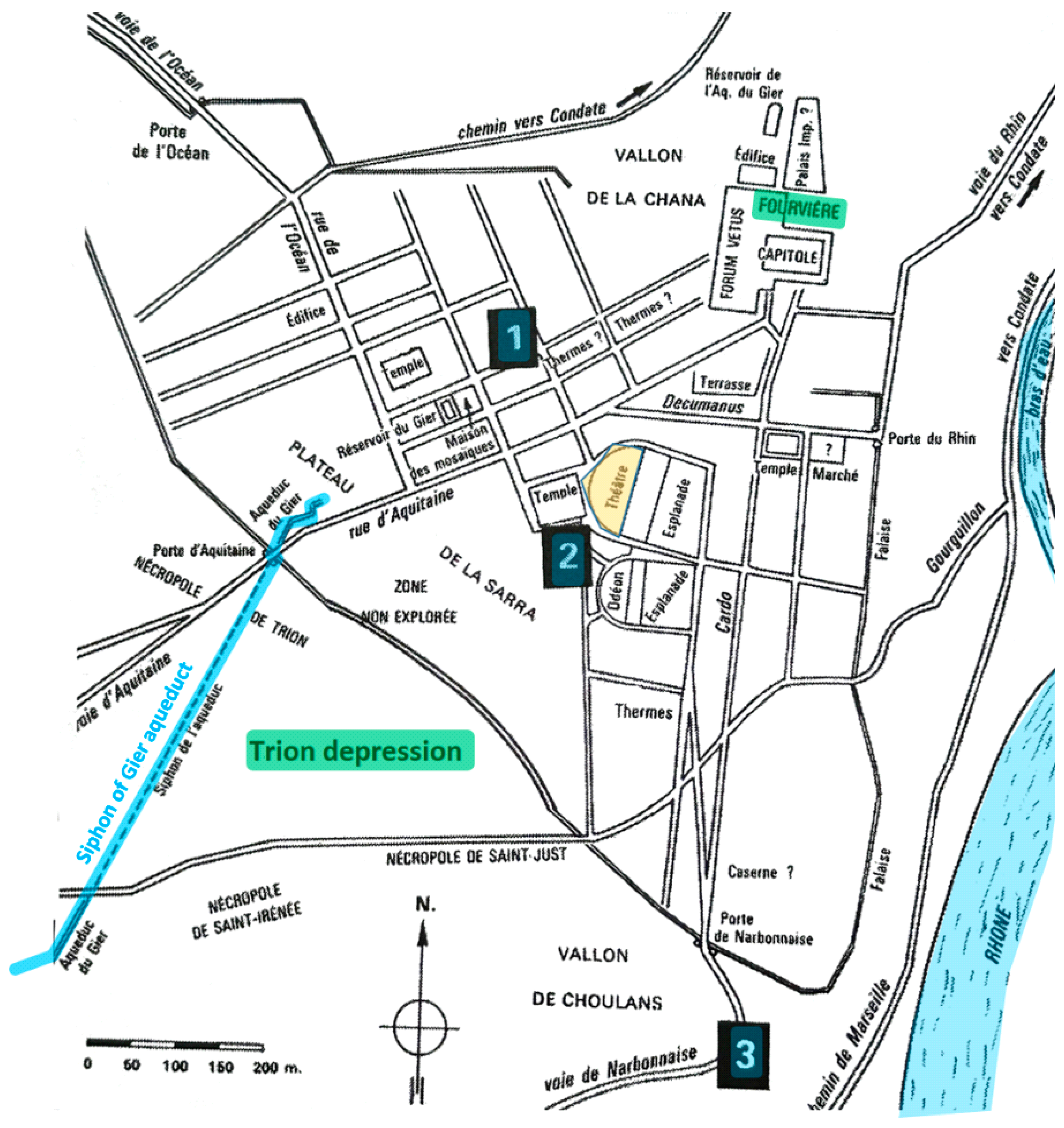
Trion at a level 265 m. After a stretch of 500 m it goes up again to the Fourvière plateau at a level of almost 300 m (see
Figure 5). At
St. Irénée, the final stretch of the channel, towards the header tank of the siphon crossing the
Trion depression, it was carried on arches, of which four piers, some 10 m high, still stand, one arch intact (
Figure 45 and
Figure 46). In later days, the
Trion header tank functioned as an observation post, using the opening of the arriving channel as an entrance that was accessed with a ladder, and for which windows were cut in the front and side walls of the reservoir (measuring 4.8 × 1.7 m on the inside). The window openings were bricked up again in 1995. Traces of holes in the front wall of the reservoir are indicative for a total of nine down-going lead conduits [
9], p. 178.
As no traces of bridge or piers have been found in the 35 m deep Trion depression, nor signs of a creek or river in this densely inhabited Lyon area, it must be assumed that the siphon conduits just ran on the bottom of the depression, to go up to the receiving tank on the Fourvière plateau.
No trace remains of the receiving tank whatsoever, but from 19th century publications it could be decided that its location was on the
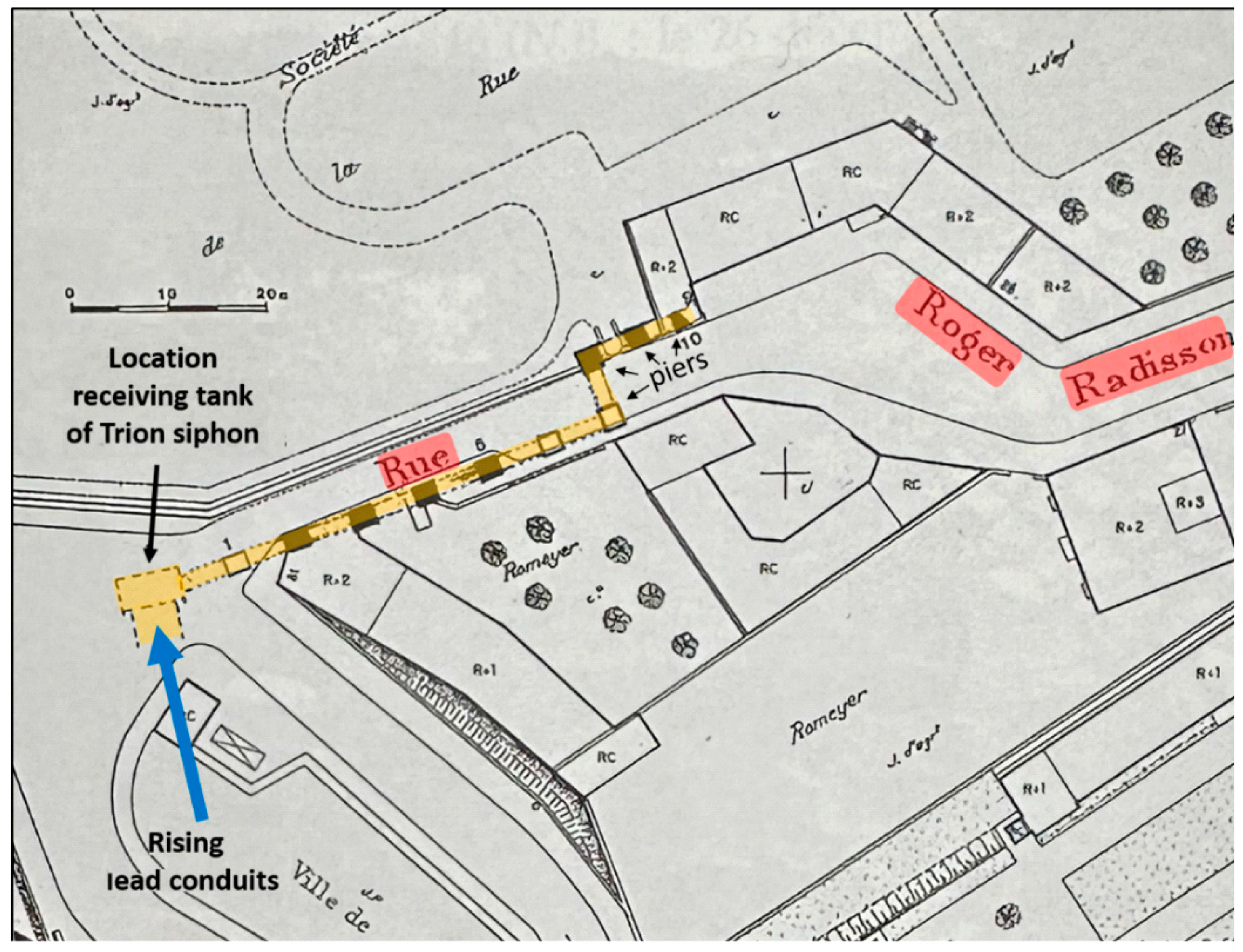
Rue Roger Radisson at a level of 299.6 m. The out-going channel, on arches, was connected to the right-hand wall of the receiving tank at square angles to the arriving lead conduits, presumably to avoid blocking a nearby road. Of this channel on arches, the location of 10 piers is known, of which 7 are still standing along the
Rue Roger Radisson, 3.1 to 4.5 m wide, interdistance 5 to 7 m, with 3 not to the full height of 6 m. Interestingly, the course of the channel here makes two square angles, counting from the receiving tank at pier no. 7 to the left and at pier no. 8 to the right, resulting in a shift of the channel one arch wide (
Figure 47 and
Figure 48) (such change of direction of the channel of 90 degrees is also know from the Arles aqueduct and from Anamur on the south coast of Turkey. Due to the low flow velocity of the water, neither the capacity of the aqueduct nor the integrity of the channel were disturbed, although some additional accumulation of calcareous incrustations may occur for high calcium containing water (not so for the acidic Gier waters)).
From the 10th pier onward the channel could not be traced. It must have ended at a
castellum divisorium or decanted in some reservoir like the 1500 cubic meter one behind the theatre, with a floor level at 288 m (
Figure 49).
The overall length of the Gier aqueduct amounts to 74.5 km, and with the Chagnon detour it is 86 km. The slope of the channel varies between 0.5 and 1.2 m/km (
Figure 50).
The enormous amounts of lead for the conduits of the siphons of the Gier and the other three aqueducts, as well as the choice of their size will be discussed below.
10. The Brevenne Aqueduct
The Lyon Mountains (les Monts du Lyonnais) range up to 933 m high and form Lyon’s western skyline at 15 km from the city. The 20 km long southwest to northeast-oriented mountain range is separated by the deep valley of the Brévenne river from the Tarare mountains further west. To the east of the Brevenne river, the Plateau Lyonnais expands with the Yzeron river and its many tributaries.
The ‘
Aqueduc de la Brévenne’, probably constructed mid-1st century CE under Claudius. [
2], p. 28, tapped springs at the elevation of 630 m on the right bank of the
Orjolle stream down from
Avieze village, springs that today supply the
Sainte-Foy-l’Argentière village 3 km to the east (
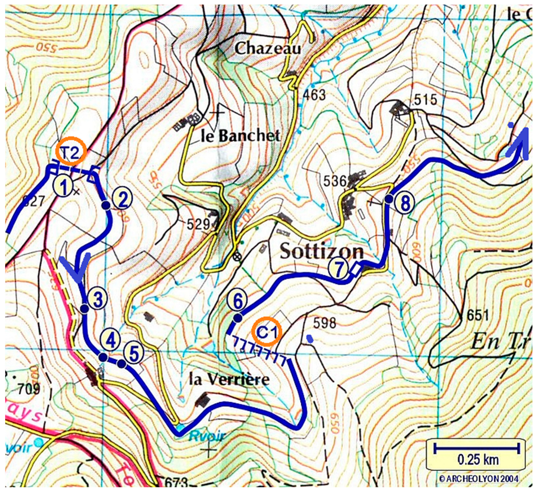
Figure 51). Of the antique water collecting provisions no trace has remained.The channel itself was found last century several hundred meters down the valley at 626.45 m. The channel down from the
Orjolle springs near
Aveize and further towards
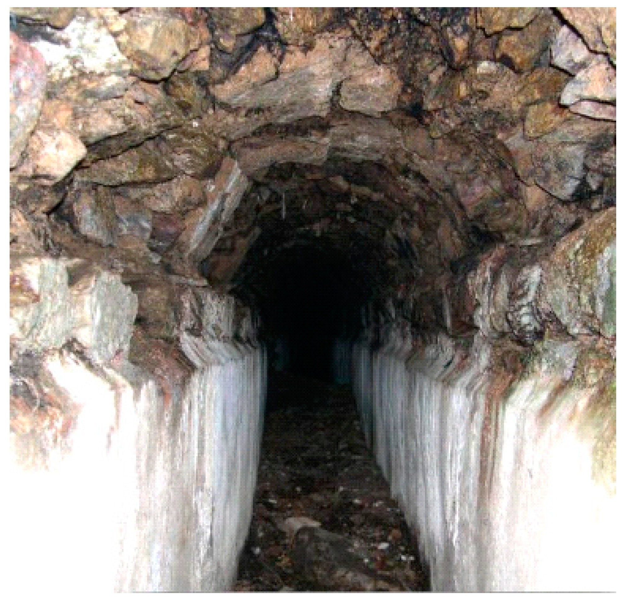
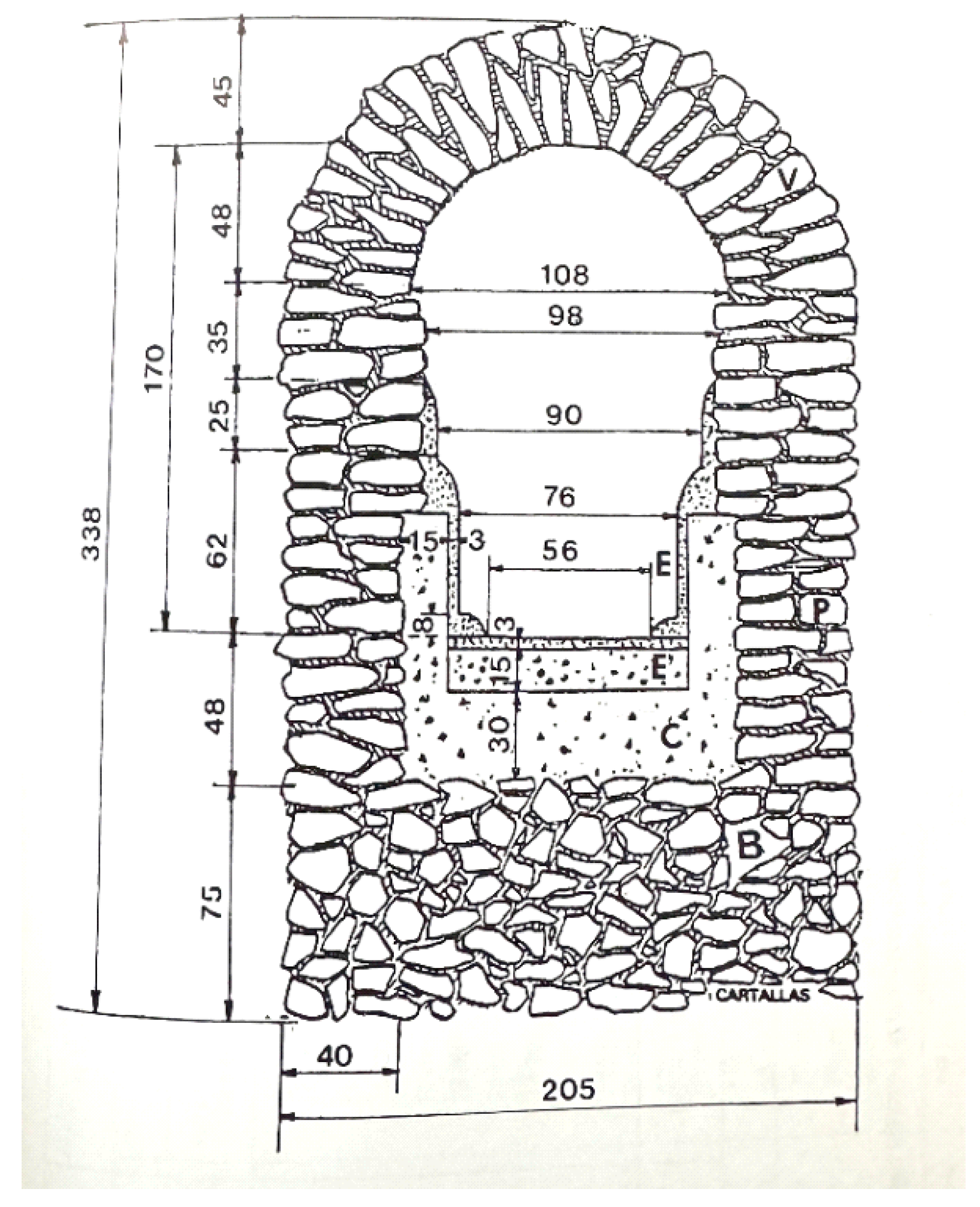
Courzieu is on the inside 54 cm wide and 150 cm high on to top of the arched vault (
Figure 52 and
Figure 53. Following the contour lines in the mountainous terrain, the winding route of the channel is at times interrupted by a tunnel and by a number of drop shafts (
Figure 54).
Near
Courzieu/La Verrière, the channel descended 44 m from a level of just over 610 m to a level of 570 m, over a distance of 200 m.
La Verrière is known for its abundant springs that today provide
Courzieu with water. Downstream of the drop shafts, at
Sottizon, the channel becomes wider and larger (
Figure 55 and
Figure 56). This channel to Lyon may have been constructed initially, tapping the springs at
La Verrière, while in later times the
Orjolle waters 17 km to the south were found suitable to be added, requiring a channel of smaller dimensions.
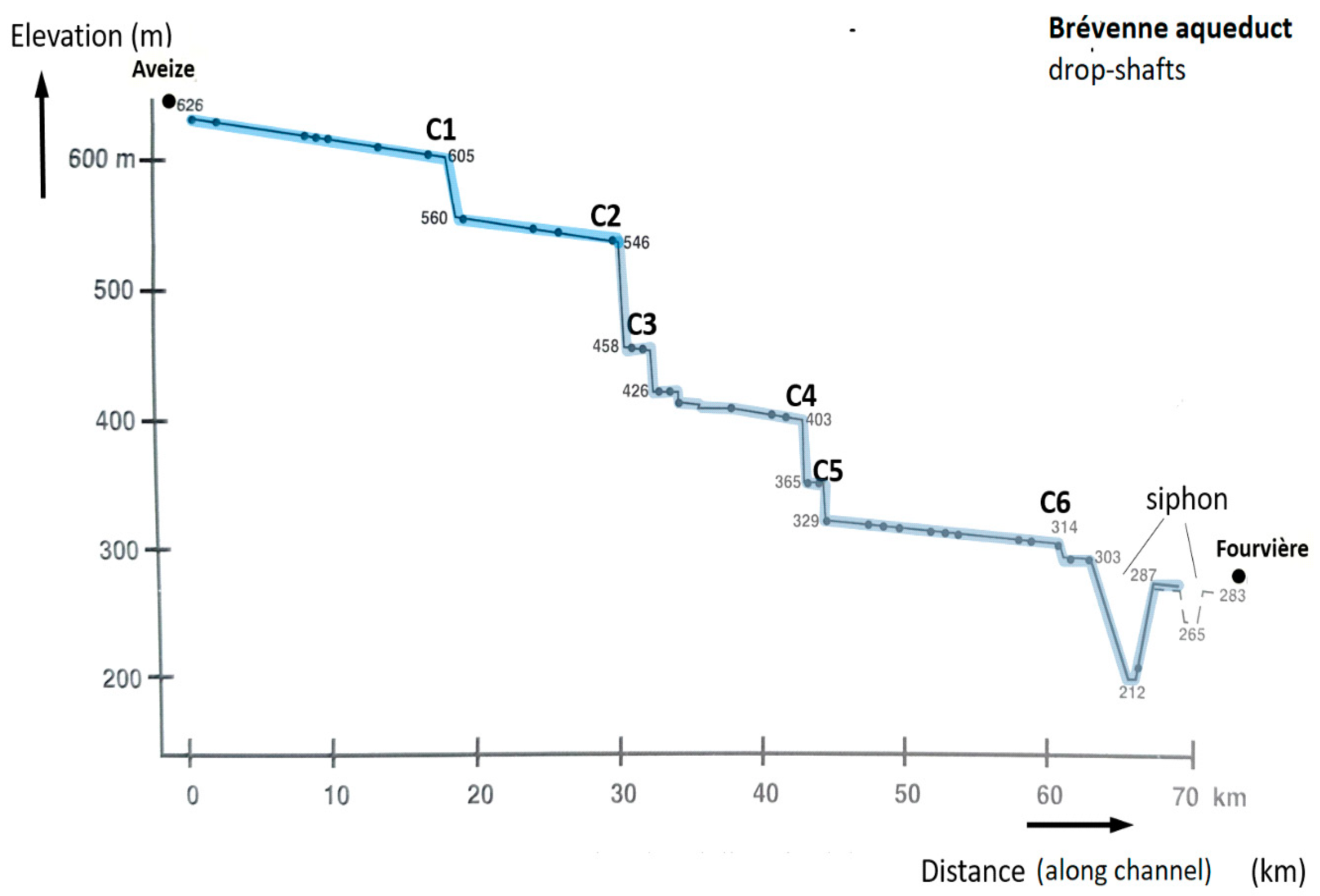
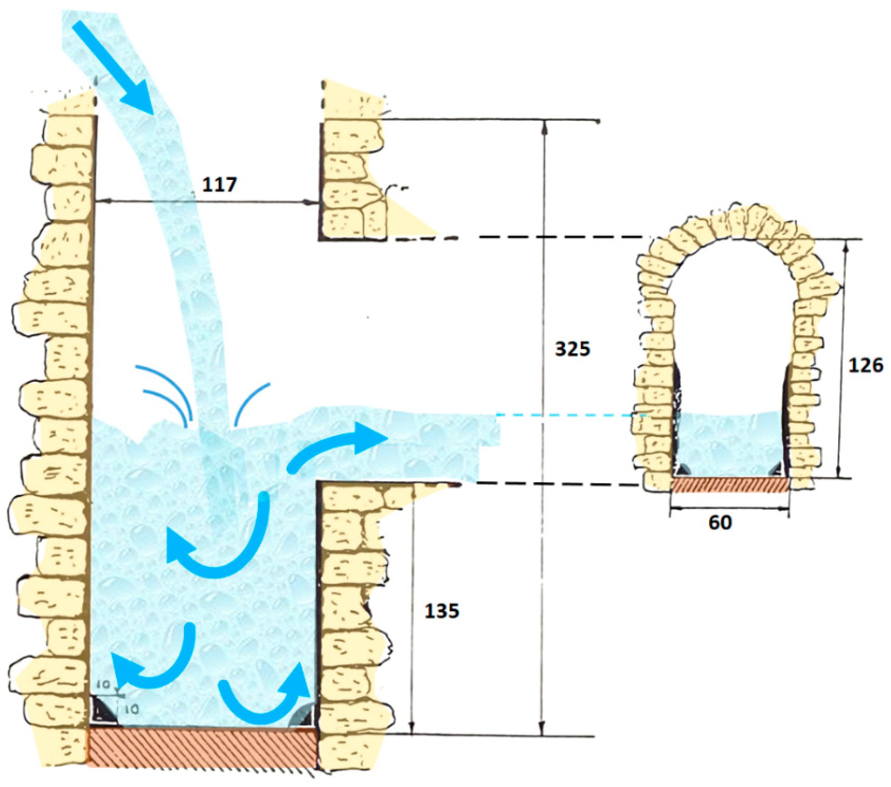
As the channel had to descend to the level of the Forvière hill at 300 m, sections with drop shafts were incorporated in the aqueduct’s course. A drop shaft consists of a vertical shaft several meters deep, into which the water falls from the channel into an ending at the shaft that is formed like a basin, and from which the water leaves the shaft again into the channelconnected to the lower end of the shaft. The purpose of (a series of) drop shafts is to reduce water velocity while substantially lowering the water level within a short distance. The departing channel is positioned above the bottom of the drop shaft so that the water falls into a water-filled basin thereby functioning as an energy dissipator preventing damage to shaft and channel (
Figure 57).
The Brévenne aqueduct had 6 drop shaft sections, of which the one near
Chevinay had a drop of 87 m over a distance of 300 m (C2 in
Figure 58). The total drop in elevation by the six sections amounts to 240 m, which is over 70% of the difference in elevation between the Orjolle springs and Fourvière (
Table 1 and
Figure 59). The four tunnels, their existence assumed from landscape arguments, had modest lengths varying from 150 m to 80 m, and depths between 12 and 16 m (
Table 2).
Just nine inspection shafts, of which four of rectangular or square shape (2 × 3 feet and 3 × 3 feet) are well preserved; the remaining ones are in bad condition and have been localised for the Brévenne aqueduct, mainly in the region around
Courzieu. This in contrast to the 63 + inspection shafts found for the Gier aqueduct [
5], p. 148 to 151.
11. The Great Siphon of Ecully-Tassin
The final section of the aqueduct required the passage of a 110 m deep and 3500 m wide valley, ‘
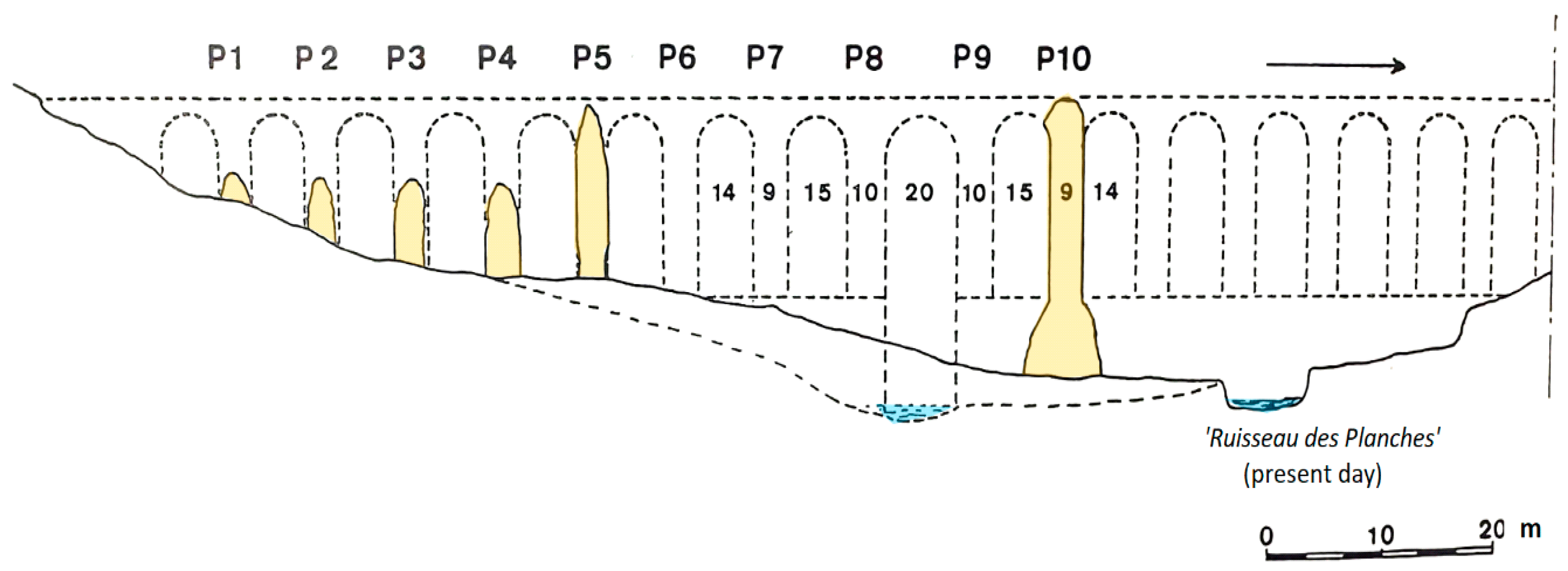
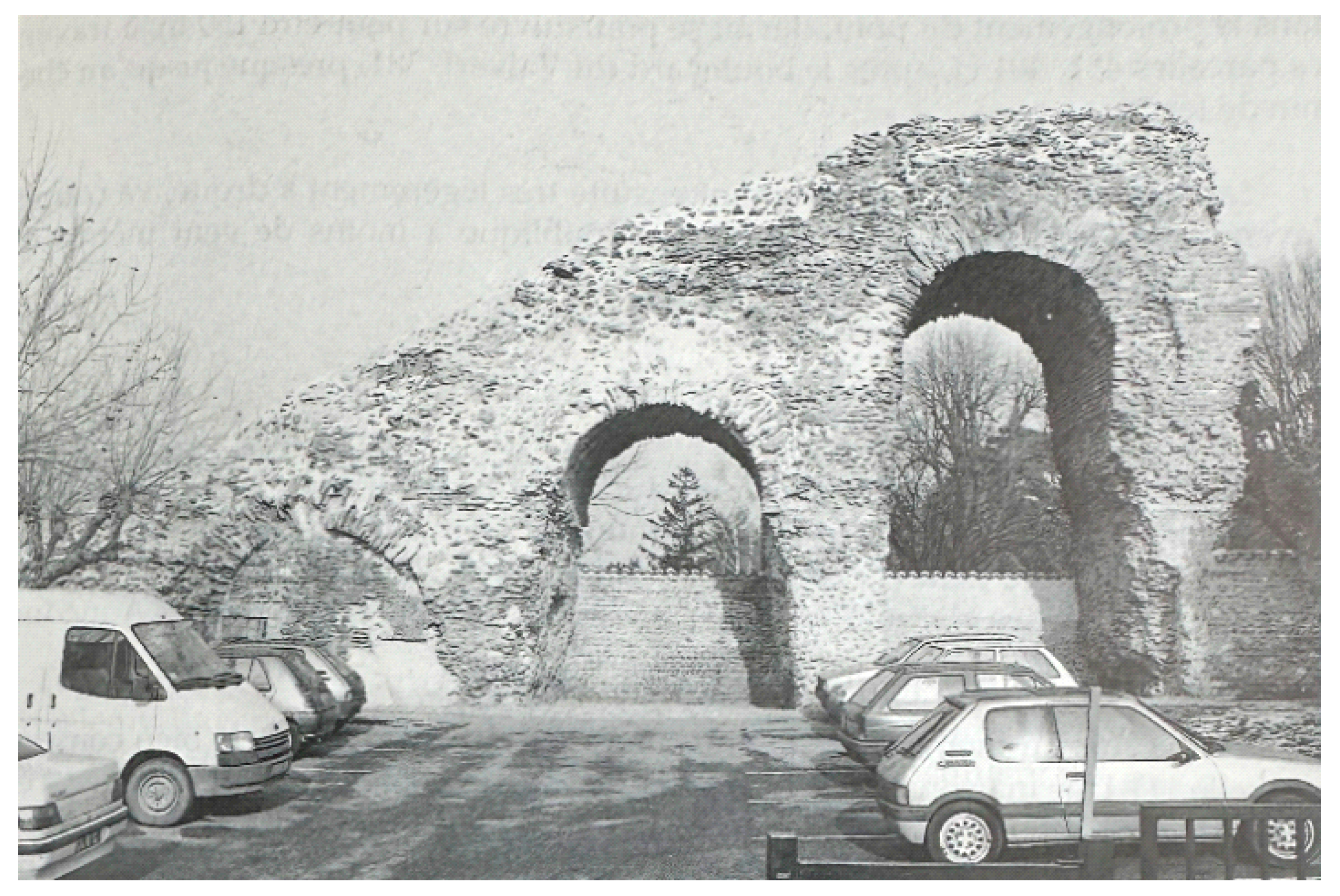
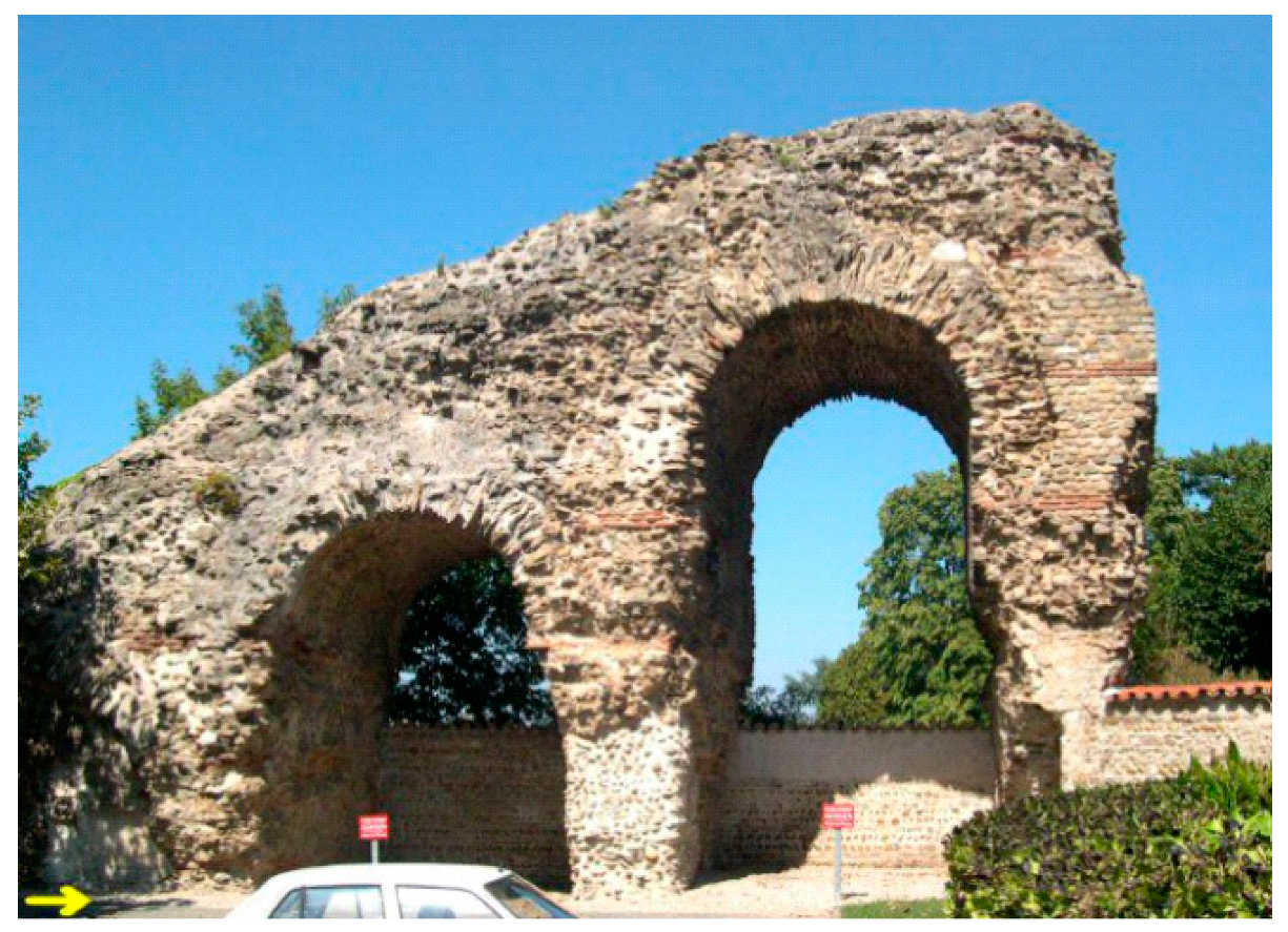
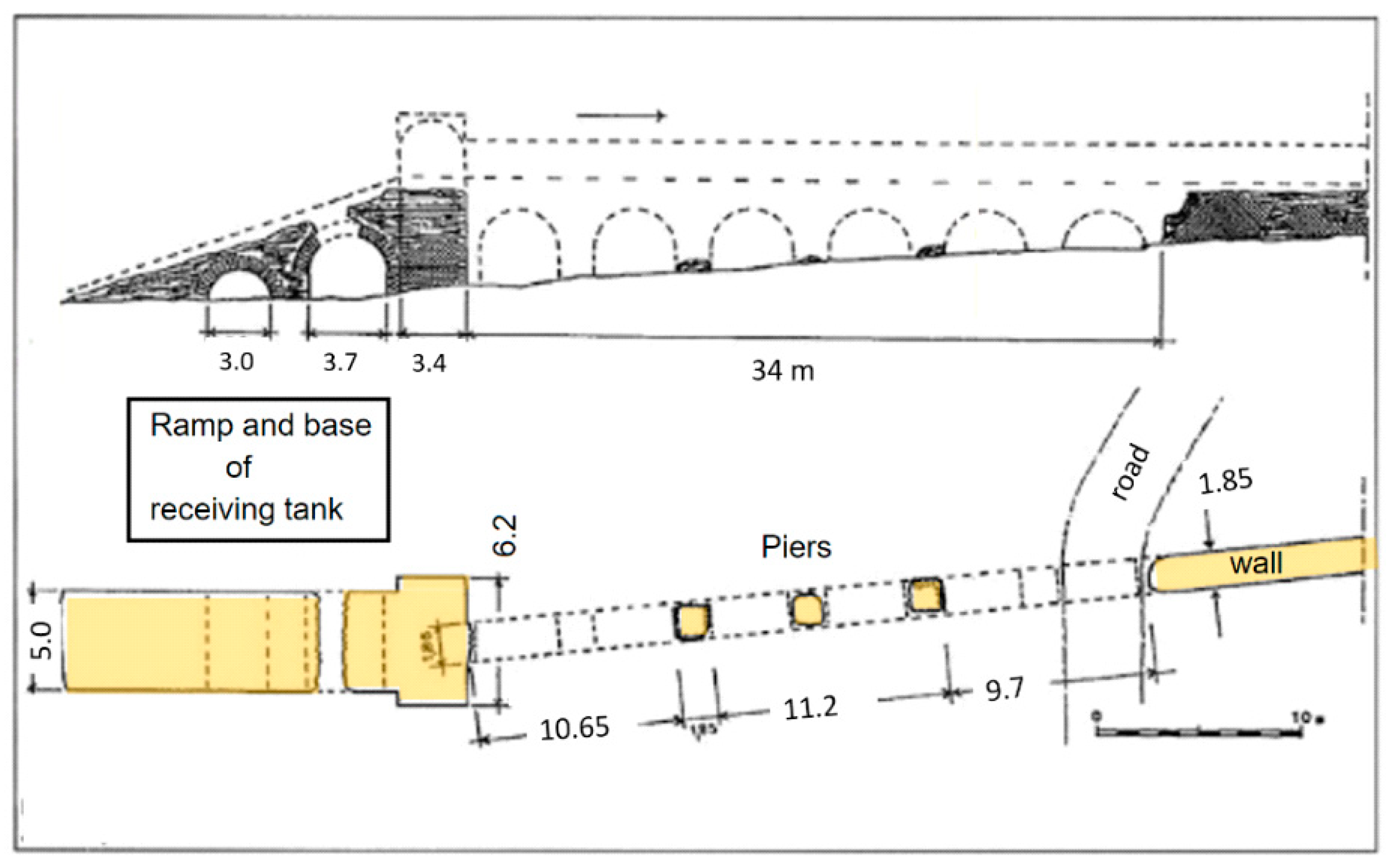
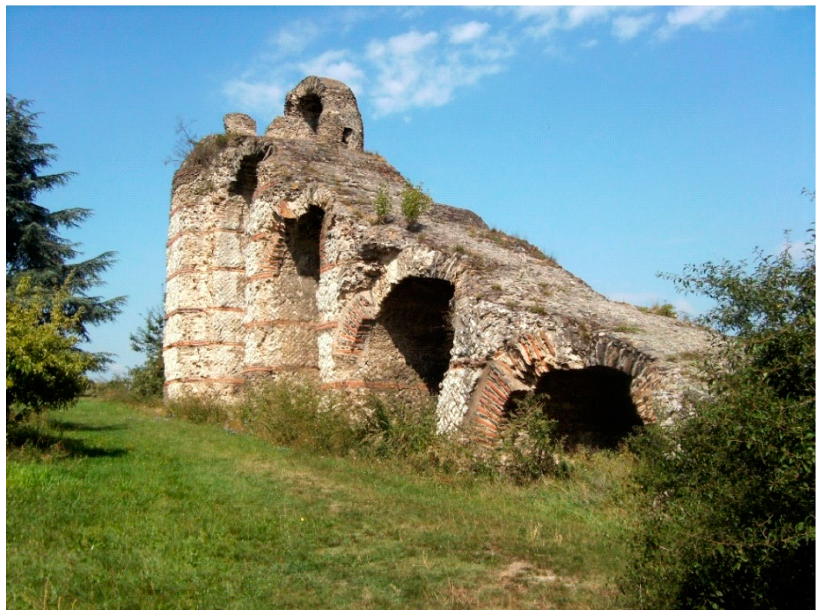
le Vallon des Planches’, which was crossed by a siphon. Of this siphon, few of the enormous piers of the 35 arches siphon bridge called the
Pont des Planches, are in ruins, but once 22 m high, some have survived, as well as the ramp up to the non-surviving receiving tank (
Figure 60,
Figure 61,
Figure 62 and
Figure 63).
Taking into account historic reports on the siphon bridge from among others (
Flacheron and
de Montauzan) while meticulously analyzing the present remains of the piers and comparing with bridges of the Gier siphon, Jean Burdy proposed a reconstruction of the upstream section of 15 piers of the bridge (
Figure 59) [
5], pp. 166–174.
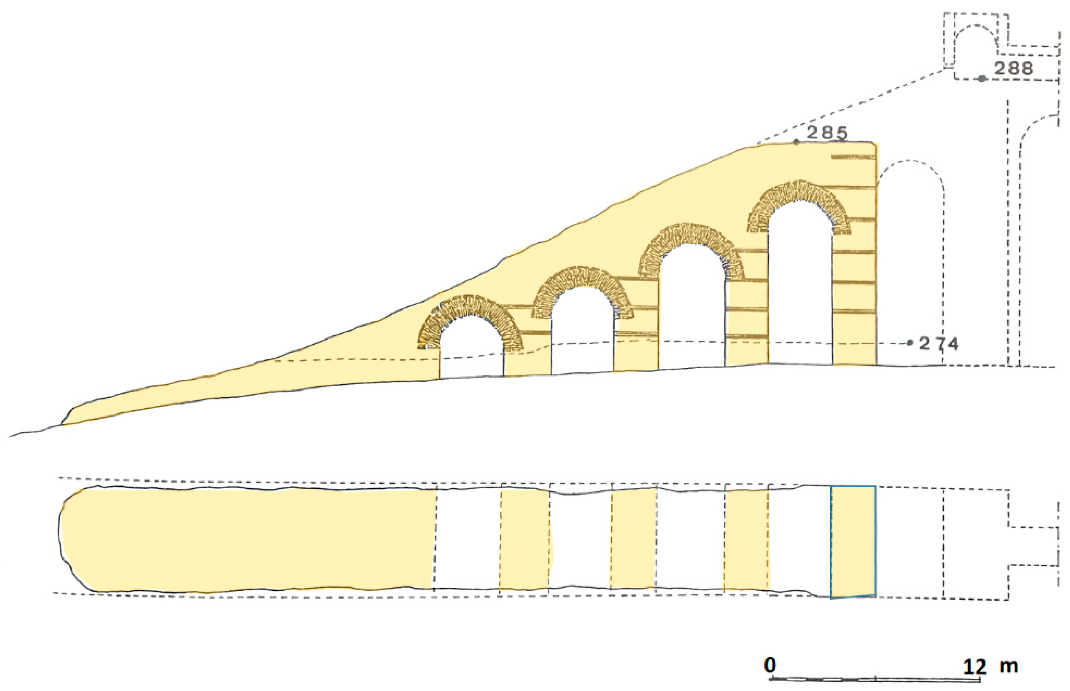
Of the receiving tank and its ramp, the latter has survived, but not the tank itself (
Figure 62 and
Figure 63). Because the receiving tank has no remains that have survived, its reconstruction is speculative to some degree, not the least of the level of the tank where the pipes of the pressure system ended.
Comparing with similar situations for the Gier siphons where the receiving tank is not constructed on top of an arch of the ramp but on a foundation/pier of its own, a reconstruction of the receiving tank at a level of 288 m appears most probable (
Figure 64).
From topographical arguments, the header tank is envisaged at a level of 302 m, the difference in level between header and receiving tank being 14 m. The siphon itself appears asymmetric, with the siphon bridge located just 800 m from the receiving tank (
Figure 65). The long 2400 m upstream section shows today a minor depression at a level of 241 m rising up to 244 before it goes steeply down to the siphon bridge (
Figure 65). This intermediate ‘high point’ in the line would interfere with the water flow because of an air pocket forming at the high point, so to avoid this, the pipes may be assumed to have been mounted in this area on a wall and then in a trench to guarantee a continuously downward slope of the conduits towards the siphon bridge [
5], p. 178. Today this area is part of Lyon’s suburbs
Ecully and
Tassin-la-Demi-Lune where, due to the modern infrastructure, no signs of such provisions have been found.
The width of 6.27 m of the ascending ramp to the receiving tank of the Great
Ecully–Tassin siphon would allow for 13 or 14 lead conduits of 25 cm outer diameter. The theoretical capacity of the siphon with pipes of 20 cm inner diameter is estimated as 26,000 to 28,000 m
3 a day, which is, in view of available springs, channel slopes and channel dimensions, as analyzed by Burdy, reduced to an effective amount of 10,000 m
3/24 h [
5], p. 185–187.
From the receiving tank onwards, the channel was carried on arches about 12 to 14 m above ground level along the
Rue des Aqueducs in the
Massues quarter, where the foundations (2.5 m wide, interdistance 3.65 m) of nine consecutive piers have been preserved. It is assumed that the channel at a level of 286 m was carried for 1200 m on some 300 of such arches and subsequently for another 300 m buried underground before reaching
St. Irenée and the
Trion depression. The 500 m wide Trion depression, lowest level at 265 m, was in its turn crossed by again a siphon towards the Fourvière hill (although a 20 m high bridge may have been possible, but no remains of piers have been found), while no bridge for a siphon was required. Header tank nor receiving tank have been preserved, and the course of the channel on the Fourvière hill is unknow [
5], pp. 156–160, 185–187.
12. The Yzeron Aqueduct
Of the Lyon aqueducts, the one taking its waters near the village of
Yzeron that gave the aqueduct its name is complex and less well known. [
2], p. 21 It is dated supposedly during the reign of Augustus 27 BCE–14 CE as the aqueduct of Mont d’Or that was first to be constructed. Just west of the
Yzeron village, springs in up to five valleys down from the tops of the
Monts du Lyonnais which form Lyon’s western skyline feed the Yzeron river (
Figure 66).
The same springs (at an elevation of 750 to 720 m) have since long supplied local settlements as they must have also fed the aqueduct, yet no structure to this end was located. At about 1 km downhill, remains of a 40 cm wide channel have been found over a length of 365 m now called
le canal de Monteroux (
Figure 67) [
8], pp. 35–38.
A section of a second channel (‘le canal superieur’) was found just along the left side of the Yzeron river bed, and it may just be that this channel also fed the aqueduct, both le canal de Monteroux and le canal superieur joining to a single channel at an unknown location uphill from Yzeron village, probably somewhere beneath the local road.
Downhill from the village to the northeast, the channel could be traced by the Burdy team at several locations, some several hundred meters apart at a settlement called
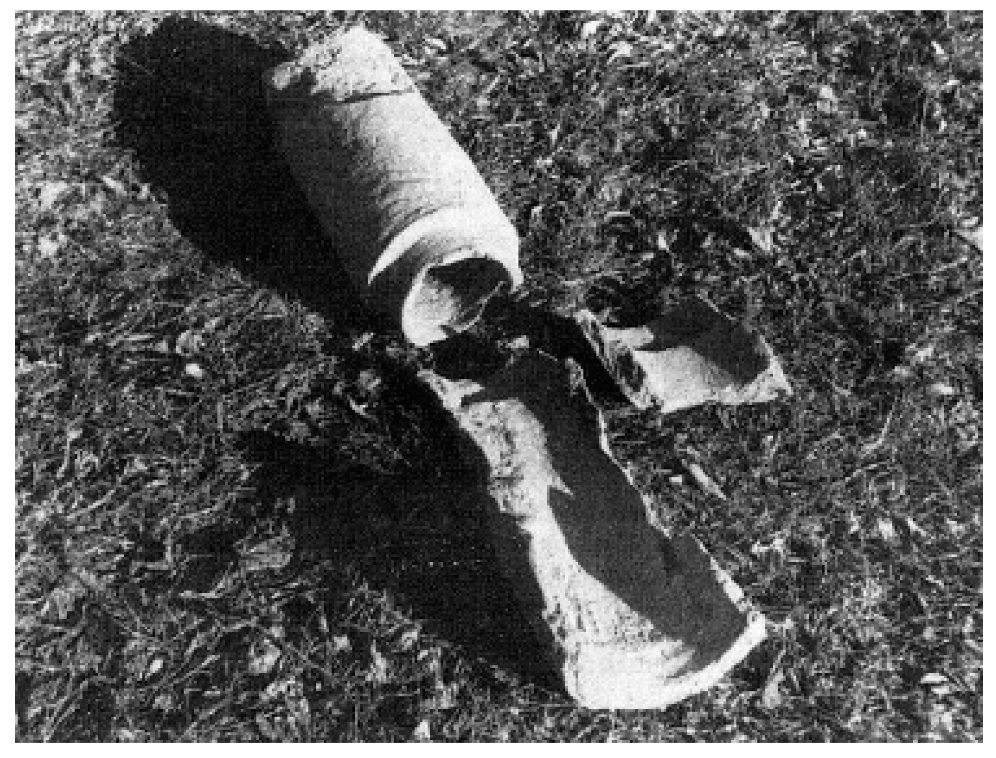
Soupat, elevation 670 m, where in 1981 roadworks by bulldozer revealed 65 m of channel, with remnants of clay pipes inside the channel. The pipes measured some 60 cm in length and 24 cm outer/15 to 17 cm inner diameter, that were also found in this channel at several more locations (
Figure 68 and
Figure 69), possibly installed to reestablish water flow after a period of neglect of the channel [
8], p. 48.
To the east, at 6.7 km from the start of
le canal de Monteroux, near the wall of a cemetery of the settlement
la Milonière, at 655 m an section of the channel was found again, also with fragments of ceramic pipes. Further east and north no traces have been found along and around the contour lines of the terrain. A hypothetical, but not proven 4000 m long system of drop shafts may have connected to drop shafts found between elevations 506 to 458 m at
Recret village (C in
Figure 66 north of
Vaugneray village) from where a channel departed to the east towards Lyon. Such an enormous drop shaft system could explain the fall in elevation from
la Milonière at 655 m to 506 m at
Recret village and onwards to 458 m, although a winding detour of the channel in the hills between
la Milonière and
Recret cannot be excluded (see map of
Figure 66, dotted line), while it may even be possible that there was no connection at all between
la Milonière and the drop shafts found at
Recret. The problem remains unresolved.
Where the channel or channels that fed the upstream end of the section of drop shafts (a ‘hydraulic stairway’) at the
Recret settlement took their water could not be established, although a number of springs are known in the hills to the north and west. Two rather intact drop shafts have been found at
Recret 490 m apart with a level difference of 38 m (
Figure 70) [
17], pp. 29–44, adapted. For a drop of about 2.5 m per shaft and accounting for a shallow slope of the connecting channels, another 11 shafts may be imagined along the 490 m stretch. The terrain east of the shaft found at the lowest elevation goes down increasingly less steep towards
Grezieux-la-Varenne, which would mean that the hydraulic stairway may have been extended some way further having longer connecting channel [
17], p. 81.
A second channel contributing to the aqueduct originates northwest of
Vaugneray village to the south of
Recret, the ‘
branche de Vaugneray’. During road constructions west of Vaugneray the channel came to light, showing a peculiar two floor levels 40 cm one above the other (
Figure 71). In
Vaugneray village itself, the channel passes underneath the church, where a hydraulic stairway is envisaged from level (elevation) 435 to level 420 m over a length of 250 m, with seven drops of some 2.5 m about 40 m apart [
8], p. 67. About 200 m downstream of the envisaged drop shaft section the channel was traced, again showing this peculiar heightening of its floor, now by 24–28 cm [
8], p. 65. Constructing a second and a higher floor level in the channel by several tens of cm while lowering the level of the channel by 15 m with drop shafts seems contradictory and remains unexplained.
After turning north, the
Vaugneray branch joined the channel coming from
Recret. Total length of the
Vaugneray branch amounts to 3900 m [
8], p. 68.
After the
Vaugneray branch joined this ‘
Grézieu branch’, the channel ran east passing the village of
Grézieu-la-Varenne towards an isolated hill at the area called
le Tupinier, to feed the header tank of the siphon of the Yzeron aqueduct at a point where the terrain goes down. The header tank, no trace remaining, is thought to have been located at an elevation of 313 m [
8], p. 83. The top of the hill is located at 311 m. Assuming that a header tank here would be of similar shape as the header tanks of the siphons of the Gier and the Brevenne aqueducts, Burdy assumes an extra 2 m for the level of this header tank. The total length of the Grézieu branch from Recret to le Tupinier is estimated at a bit more than 5 km.
13. The Siphon of the Yzeron Aqueduct
The terrain extending towards Lyon east of
le Tupinier goes down some 30 m to a 2 km wide plane at 280 m elevation, located between the deep valleys of the Yzeron river to the south and of the Ratier stream to the north. The terrain remounts again near the settlement of
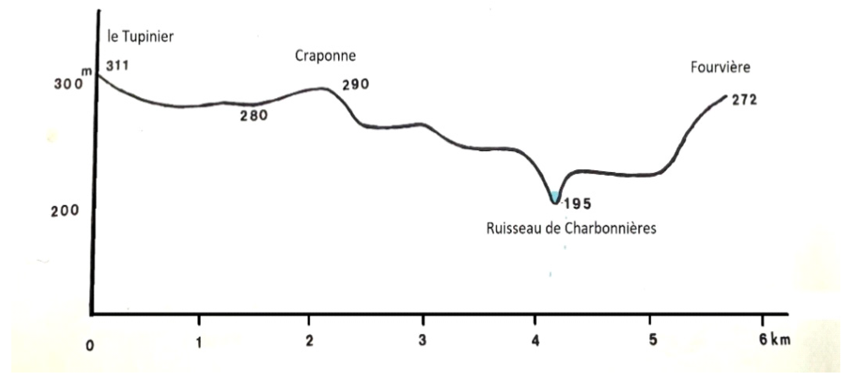
Craponne to a maximum elevation of 290 m. Further east the terrain again loses height rapidly over a distance of about another 2 km to the valley where the Charbonnieres stream flows at a low 195 m elevation to join the Yzeron river to the south. Then, after some 500 m, the terrain rises steeply up again to an elevation of 272 m at Fourvière (
Figure 72).
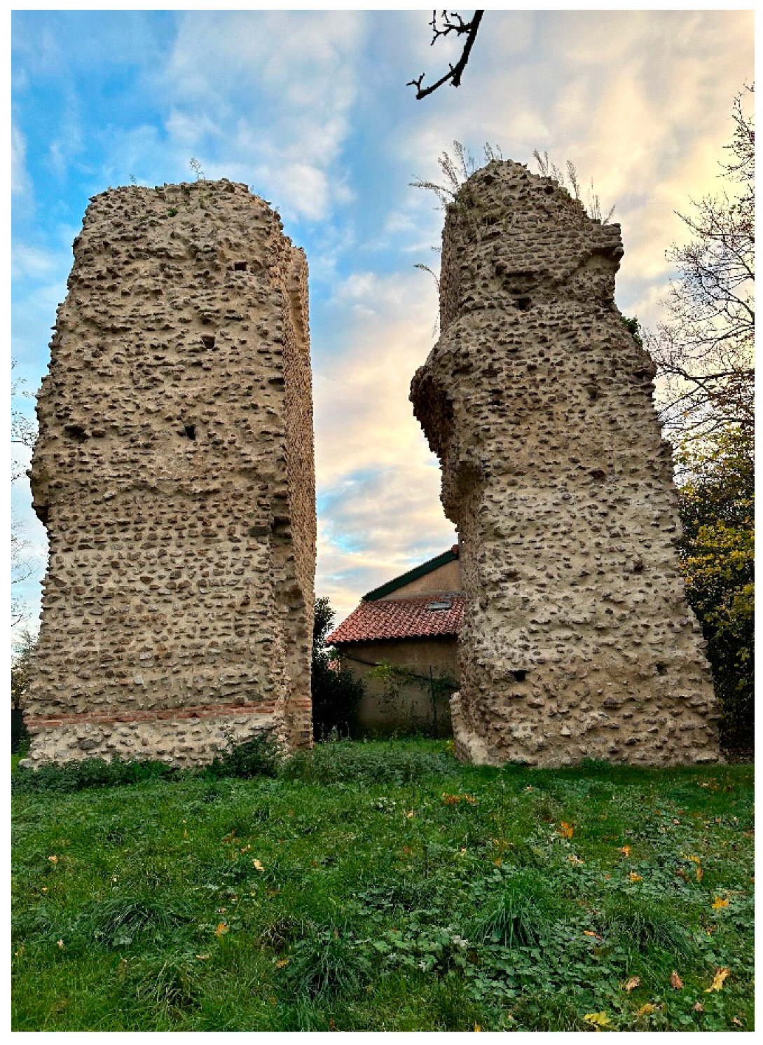
On the 290 m top near
Craponne, two 12 m high square piers stand, measuring 4.40 × 4.40 m and 4.40 × 3.77 m, 2.80 m apart (
Figure 73 and
Figure 74). The two piers are since long known as ‘
les Tourillons de Craponne’. First mention dates from 1599 as ‘La tourray’ on a medieval map [
8], p. 3. The piers were restored in 2019 to prevent further degradation, during which ooccasion a study of the structure of this construction was carried out [
18].
Some tens of meters further east, two more remains of piers as well as of a wall rise up 1–2 m from the terrain, all arranged in an east–west line (
Figure 75). The left pier in
Figure 73 shows remnants of an arch on either side, but the reason for this remains unclear. Various authors presented various explanations for these massive structures, from a monumental gate to an encampment built by Julius Caesar or Marc Antony, or a triumphal arch, to a bridge and even a quay on an ancient course of the Saone river [
8], p. 89.
Towards the end of the 19th century, the idea that the piers were part of an aqueduct, or rather of a siphon equipped with a tower with an open reservoir on top to release air (
’ventouse’) became increasingly in vogue, supported by an 1862 report of the
XXIX Congrès archéologique De France at Lyon of a find 60 years before of a great number lead pipes east of the piers that the local farmers had melted down on the spot into ingots [
8], p. 21. Moreover, in the low plane between le Tupinier and Craponne, no remains of piers had been found, so that the continuation of the aqueduct channel at le Tupinier on a bridge towards les Tourillons was not deemed probable, a bridge that had to be over 2 km long and 30 m high.
Various reconstructions were proposed, among others by Germain de Montauzan with sloping ramps on both sides, supported by further remains at ground level west and east of the piers, carrying lead conduits up to an open reservoir on top [
8], pp. 92–96.
The most recent reconstruction is by Burdy, with an open reservoir on top of the 4.40 × 4.40 m pier at an elevation of 316 m (
Figure 76).
Once the idea of a siphon was accepted, the over 3 km long stretch towards Fourvière, with the
Ruisseau de Charbonnières flowing at 195 m elevation, had to be covered as well. In the 1880s during the construction of a new traffic bridge (
Pont d’Alaï), massive foundations of a Roman structure including large limestone blocks with connecting iron cramps sealed with lead and parts of arches came to light, which were interpreted as the remains of the bridge on behalf of the siphon crossing the
Ruisseau de Charbonnières. The findings were confirmed again in 1969 during works in relation with a large sewer system beneath the
Pont d’Alaï. The bridge is thought to have been 20 m high, the siphon passing the
Ruisseau de Charbonnières at an elevation of 215 m (
Figure 77 and
Figure 78) [
8], pp. 97–99, adapted.
After passing the
Pont d’Alaï, the siphon, first turning a bit to the right and proceeding horizontally for some 600 m, had to go up the steep east side of the valley of the
Ruisseau de Charbonnières towards Lyon, where the receiving tank is envisaged at an elevation of 273 m (see below). With the open reservoir on top of the tower at Craponne, the siphon is split up into two, with two siphons connected end to end, the open tank in between serving both as receiving tank and as header tank, a double siphon. Of the remains of the siphon bridge, little may be seen today, just one block of the foundations near the modern traffic bridge, the
Pont d’Alaï, on the left side of the
Ruisseau de Charbonnières (
Figure 78).
Until the 1990s, it was unclear where the siphon ended, whether there was a continuing channel, and where it went. However, in June 1990 during ground works on behalf of new edifices, a channel was found at no. 53 of the ‘Rue Joliot-Curie’ 120 cm below ground level, of which 20 m was already removed before archaeological inspection could be performed on a subsequent 20 m section, after which this part was destroyed as well with no remains preserved. The 62 cm wide channel had walls 40–45 cm wide, the floor of the channel being at an elevation of 271.8 m. This elevation conforms to the proposed elevation of the receiving tank at 273 m.
The discovery of the channel at the
Rue Joliot-Curie allowed for a reconstruction of the course of the channel in this area called ‘
Plat du Jour’ just south-west of the Fourvière hill and the Trion depression where the siphons of the Brevenne and the Gier aqueduct pass to Fourvière. Following the irregularities of the terrain the channel would have a sinuous course and may have crossed the channel of the Mont d’Or aqueduct some 8 m above it, ending just south of the Baths and the Roman Theatre/Odeon at elevation of 268 m (see
Figure 5). Length of channel from receiving tank to end point about 3.85 km.
14. Les Tourillons de Craponne
One wonders what the reason was for this 5.8 km long siphon to construct an open tank 2.2 km downstream from the header tank on a tower 16 m high with sloping ramps on either side, and that on top of a hill at an elevation of 290 m?
About 80 siphons are known from classical times, the majority of them of the ‘simple siphon’ type, as shown in
Figure 14.
Few are equipped with a hydraulic tower such as ‘Tourillons de Craponne’. These hydraulic towers were often installed on an intermediary hill in the path of the siphon, but there were also siphons with intermediary hills and no hydraulic towers, and siphons with hydraulic towers but no intermediary hills (
Table 3). The conduits of the siphons were made of prefabricated lead pipes, connected together on site, with soldered joints as was the case for the siphons of the Lyon aqueducts, or of stone/terracotta pipes with weak male/female joints that had been made watertight with a mixture of quicklime and oil that expands when in contact with water but that has low tensile strength. The hydraulic towers are thought to release air from the closed conduit of the siphon.
City water distribution systems as in Pompeii and Herculaneum (lead conduits) and also in the east (e.g., Laodikeia, (Turkey, stone and ceramic conduits) applied low pressure siphons which included hydraulic towers to keep the pressure elevated. Compared to siphons in aqueducts, this rather low static pressure was sufficient to serve second stories in houses, as may be seen in Pompeii. This ‘Pompeian’ type water distribution system with hydraulic towers was common practice in Europe until the late 18th, early 19th century, and even later, as in Palermo, Sicily, until in the 1960–1970s [
20].
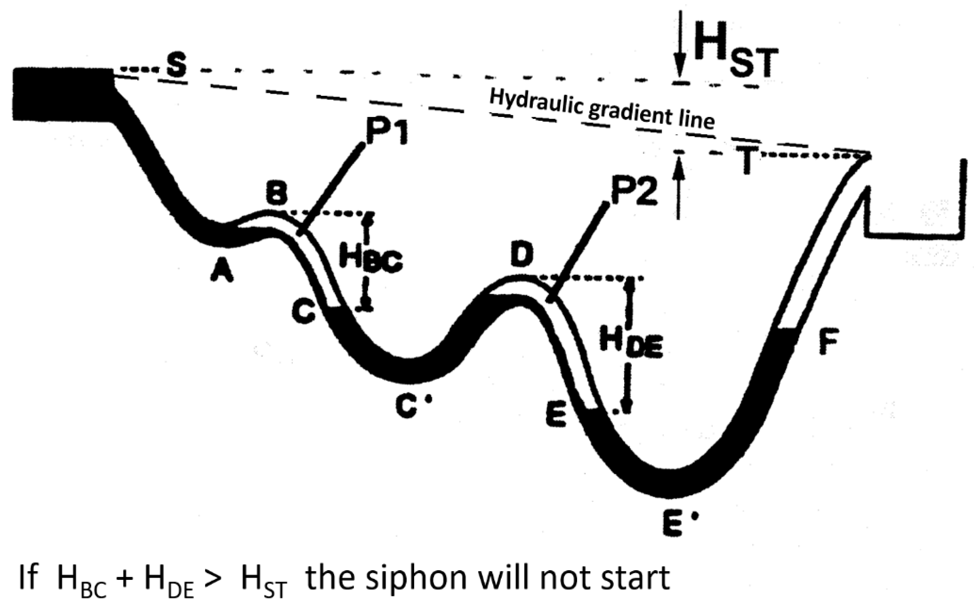
But how to start a siphon? It is not difficult for a simple siphon: fill it slowly with water from the header tank, and when the water reaches the receiving tank, slowly increase the water flow to the maximum quantity. Filling a siphon with an intermediate hill, a ‘high point’, is another matter. When the conduit that crosses an intermediate hill is filled with water, an air pocket will form downstream of the hill top because air tends to rise up in water, and as such, the air pocket cannot escape.
In
Figure 79, a siphon with two intermediate hills (two high points in the line) is shown schematically. When filling this siphon, air pockets will form downstream of the high points. If the combined vertical heights of the air pockets is greater than the difference in height between header tank and receiving tank, the water will not reach the receiving tank and the water will not flow: an airlock has been created, and the siphon does not start. On the other hand, the air pockets are partly compressed by the water pressure, so that this effect is reduced. In such case, the siphon may start and operate at reduced capacity. When starting at reduced capacity, air entrainment at the header tank may subsequently enlarge the air pocket leading to an incurable standstill.
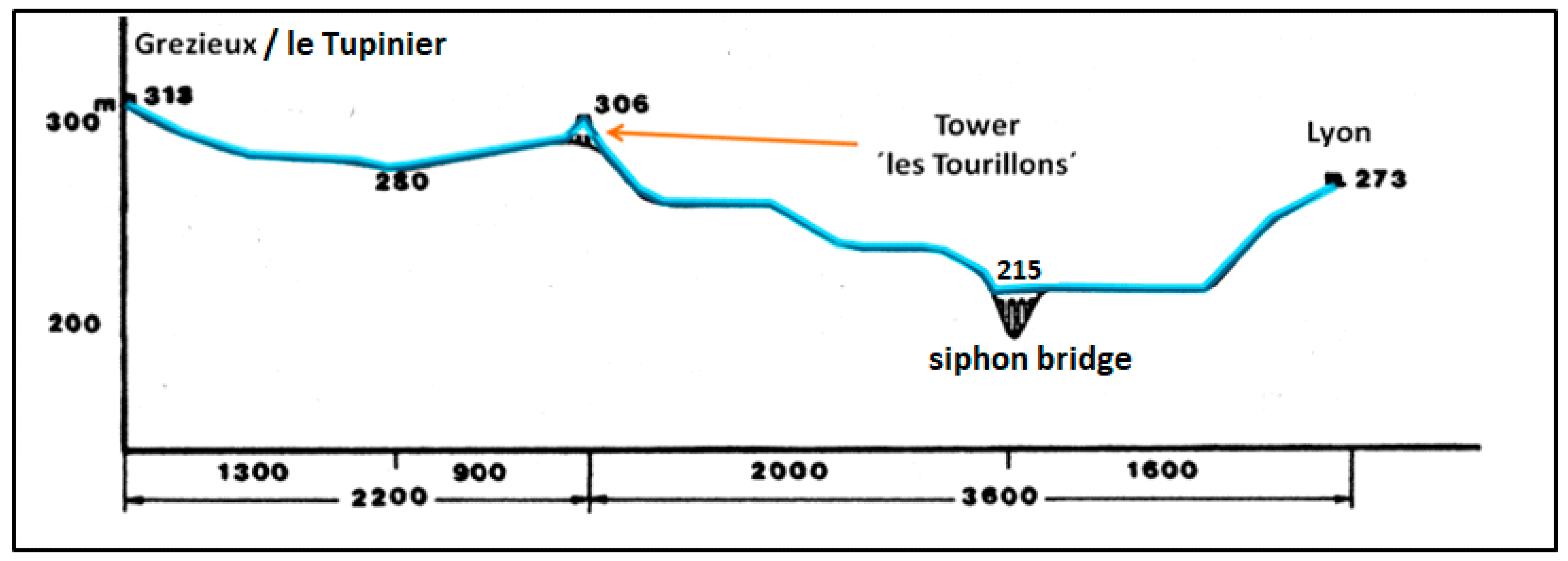
The 16 m high tower of les Tourillons with the open tank on top to release air must have been built on purpose, but why? The profile of the Yzeron siphon as shown in
Figure 70 has a high point at 290 m. Could this high point have been avoided?
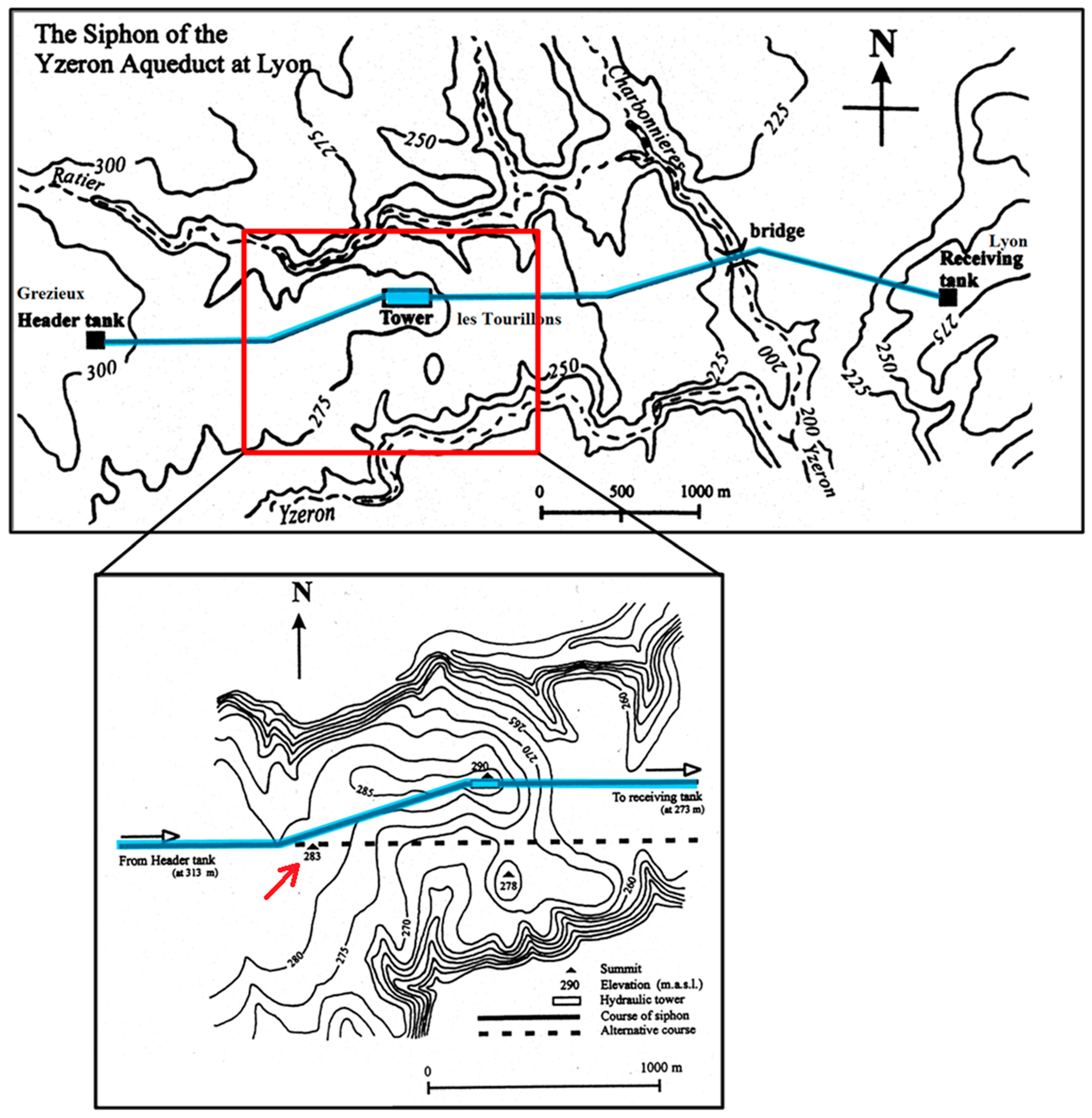
Figure 80 shows a map with the siphon’s course. It may be seen that from the header tank, the siphon extends east between the deep valleys of the Ratier river to the north and the Yzeron river to the south, and finally crossing the Charbonnières stream by means of a 20 m high bridge where today the
Pont d’Alaï serves the modern traffic as discussed above. The siphon has three horizontal bends (not counting the
les Tourillons tower at Craponne, which for the lead conduits with strong joints between pipe elements may not be problematic (see for the various aspects of classical siphons and their problems, [
1], pp. 12–59.
The tower of
les Tourillons was built on a top of a hill at 290 m (inset), which must have been deliberately chosen for its construction. Just west of the 290 m high point, a lesser hill at 283 m was avoided by the siphon. The dotted line in the inset represents an alternative course of the siphon which, however, would incorporate this lower hill. The shallow depression downstream of this hill could have been leveled out with a wall to avoid a second high point just downstream. Whatever the case and whatever the course, the Yzeron siphon had to deal with a high point, either at 290 m positioned at 2200 m from the header tank, or at 283 m at 1500 m from the header tank, the plane downstream of the header tank being at a level/elevation of 280 m. This means that in either case, an open tank was obligatory for the siphon to avoid reduced capacity at start up with even the possibility of an incurable standstill due to air entrainment at the header tank (Air entrainment at the header tanks of classical siphons was common due to the insufficient depth of the intake below the water level in the header tank. See [
1], p. 47; for the les Tourillons case: [
22], in French.
So if an open tank at a high point, either at 290 m or at 283 m (the receiving tank being at 273 m, see above) would guarantee the water flow, why built a 16 m high tower with sloping ramps on top of the 290 m hill to have an open tank at an elevation of 306 m? Let us compare the two situations: an open tank at 306 m elevation on top of the 16 m tower, and an open tank 16 m on top of the 283 hill.
The 4.4 × 4.4 m open tank on top of the les Tourillons tower is estimated by Burdy to have walls 60–80 cm thick, the reservoir being 2.80–3.20 m wide on the inside. This leaves room for six or seven lead pipes (at the most), pipes with an external diameter of 25 or maybe 23 cm as Jean Burdy proposes (internal diameter 20 cm or 18 cm), similar as for the siphons of the Gier aqueduct. Such a reservoir may also be imagined on top of the 283 m hill. We have to consider two situations, each with two consecutive siphons that differ with respect to the position of the intermediate open tank, and thus with the driving force for each section, assuming for each case lead conduits of similar dimension.
Burdy estimates that the open tank on top of the tower of
les Tourillons could accommodate six or seven lead pipes of 25 cm outer diameter, and calculated that the total discharge Q, with a level difference ΔH of 7 m between header tank and the
les Tourillons tank. With 20 cm inner diameter of the pipes, the total discharge Q would be about 13,000 m
3 per day. As a consequence, the 13,000 m
3 per day must be considered the average capacity of the Yzeron aqueduct. Burdy also estimated that because of the greater ΔH of 33 m between the tank of
les Tourillons and the receiving tank, only four pipes would suffice for the longer stretch of 3600 m, [
8], pp. 122–123.
The average velocity V of water in a pipe of length L can be estimated with the Darcy-Weisbach formula (See
http://www.pipeflow.co.uk/public/articles/Darcy_Weisbach_Formula, accessed 10 April 2024):
with g = 9.81 m/s
2; ΔH = driving force (m); Rh = hydraulic radius, for fully filled pipe Rh = D/4; D = inside diameter of pipe (m); λ = factor related to pipe wall roughness; L = pipe length (m).
For identical pipes, we may write V
2 = ((8·g·Rh)/λ)·∆H/L = C·∆H/L with C = 8∙g∙Rh)/λ. This means that the velocity V of the water in identical pipes (C has a fixed value) depends only on the square root of ∆H/L. In the expression V (:) (ΔH/L)
1/2 the water transport Q (volume per time) in a pipe of inner cross-section O is V·O. As V (:) (ΔH/L)
1/2, then also Q (:) (ΔH/L)
1/2. The ∆H between header tank and intermediate open tank for the situation I is larger than for situation II (with
les Tourillons), see
Table 4 above, so that pipes in the upstream section in situation I would transport more water; that is, fewer pipes were needed here for the same discharge of the arriving aqueduct.
What are the consequences? Any pipe in the 1500 m section towards the open tank at 283 m would transport more water per pipe than in the 2200 m section case of
les Tourillons, the water transport Q being related to (ΔH/L)
1/2 as discussed above.
Table 5 gives the value of (ΔH/L)
1/2 for each section in both situations.
Each pipe in in the 1500 m section delivers more water than any pipe in the 2200 m section with
les Tourillons, that is, 0.1414/0.0564 = 2.507, say, 2.5 times more. Fewer pipes are needed in situation I to have the water, that arrives at the header tank, to be transported to the open tank at 283 m, or 7/2.5 = 2.8, say, three pipes. Moreover, from
Table 5, it may be estimated how many pipes would suffice for the 3600 section of situation II: each pipe in this section delivers a factor 0.0957 compared to 0.0564 for the 2200 m section, that is, 0.0957/0.0564 = 1.70 times more water. For the seven pipes of the 2200 m section, only 7/1.70 = 4.12 (say four) pipes are needed for the 3600 m section, conforming to the estimate of Burdy mentioned above.
On the other hand, the downstream section needed in situation I may be estimated as well. The three pipes needed in the upstream section with capacity Q (:) 0.1414 must be compared with the pipes in the downstream section with Q (:) 0.0482, that is, the latter pipes have a capacity of 0.0482/0.1414 = 0.34 times that of the pipes in the upstream section. Thus, for the 2.8 (say, three) pipes in the upstream section there are needed 2.8/0.34 = 8.2, say, eight pipes, in the 4300 m downstream section.
The total length of the lead conduits needed for each situation may now be calculated, see
Table 6. It will be seen that situation I, with an open tank on top of a 16 m high tower on top of a 290 m hill, required fewer long conduits than for situation II, with an open tank on top of the 283 m hill. For both situations, an open tank was obligatory for the functioning of the siphon. However, the building of a 16 m high tower on top of the 290 m high hill saved 9 km of lead conduit. While lead metal was an expensive commodity, in the immediate environment sufficient building stones for constructing
les Tourillons were available.
This means that the construction of the 16 m high tower with open tank/reservoir on top on a hill at 290 m compared with an open tank on top of a hill at 283 m saved 9 km of lead piping of 23 or 20 cm outer diameter and 20 or 18 cm inner diameter. That is almost 1800 tons of lead. The decision by the Roman engineers to construct
les Tourilons de Craponne for the siphon of the Yzeron aqueduct was a rational one: it was less expensive The overall profile of the double siphon of the Yzeron aqueduct is shown in
Figure 81.
15. Discussion
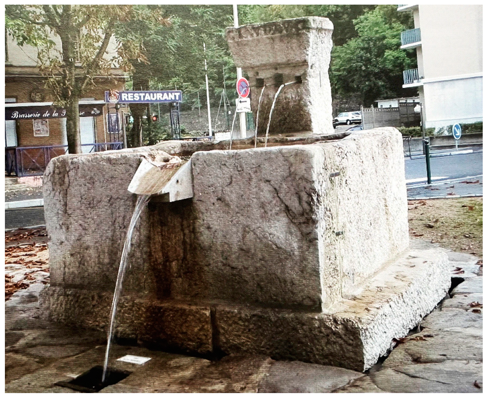
The four aqueducts of Lyon were built in a time span of one and a half century, from about 20 BCE (Mont d’Or aqueduct) to 140 CE (Gier aqueduct). Only the Gier aqueduct provided the entire city on the Fourvière promontory, the other three aqueducts reaching lower sections of the town including some public fountains (
Figure 82,
Figure 83 and
Figure 84).
By the end of the 3rd century CE under Diocletian, Lugdunum loses her title as capital of the Gaules, after which decline set in. In the 4th century, the city was deserted and the aqueducts lost their function, the lead of their siphons becoming subject to pillaging [
2], p. 28. The enormous amount of lead for the four Gier siphons alone is estimated to have been 10,000 tons, assuming lead pipes of 23 cm outer diameter and a wall thickness of 2.5 cm [
9], pp. 269–275. Where did all the lead come from?
Pliny the Elder mentions that lead is to be found in Spain and Gallia, but especially in Britannia in great amounts: Pliny the Elder XXXIV ch 164 [
24]: ‘Nigro plumbo ad fistulas lamnasque utimur, laboriosus in Hispania eruto totasque per Gallias, sed in Brittannia summo terrae corio adeo large, ut lex ultro dicatur, ne plus certo modo fiat’. Translation: Black lead is used for water pipes and sheets, and is laboriously delved in Spain as well as in Gallia, but in Brittannia it is in the upper soil in such great quantities, that a law is said to have been issued, that one can only take certain amoun (Translations of Brittannia may vary from England to Bretagne).
The question is, why were multiple pipelines chosen for the Lyon siphons? No multiple-conduit siphons are known from classical times except at Lyon. The two parallel stone siphons at Laodikeia a/L had each a separate header tank and receiving tank [
21], p. 152. Could not a single conduit have sufficed to transport the water to Lyon?
Lead conduits of siphons have been found, for instance at Arles and at Vienne, to cross the Rhône on the river bed [
25,
26]. Diameter and wall thickness of these conduits are, respectively, 10 cm/1.2 cm and 32 cm/1.6 cm. For the Lyon siphons, lead conduits of 23 cm outer diameter and wall thickness 2.5 cm will be taken as ‘standard’ in the discussion below, although a wall thickness half as wide may be regarded as an option.
To see whether a single conduit siphon would do for Lyon, one has to regard the water transport by means of say 10 conduits with internal diameter, e.g., 18 cm (outer diameter 23 cm wall/wall thickness 2.5 cm), and see what diameter pipe would transport the same amount of water for the same siphon stretch.
The velocity V of water in a pipe may be estimated with the Darcy–Weissbach formula as mentioned above:
V2 = (8∙g∙∆H∙Rh)/(λ∙L), with Rh = D/4 for full pipe flow, D = 2R = internal pipe diameter, R = internal pipe radius.
For the same siphon length L and the same difference in level between header tank and receiving tank ∆H, as well as for the same material of the pipe (wall roughness λ), the flow veleocity only depends on Rh, that is, on the internal pipe diameter, V2 depends only on D, that is, V2 depends only on R so V depends only on R½.
The water transport Q through a pipe of internal radius R is equal to the water velocity V in the pipe times the cross-section area O of the pipe: Q = V·O, where O = π·R2. So, in this case Q depends only on R½·R2 or R5/2.
Thus, the water transport by 10 conduits of 18 cm inner diameter (with radius 9 cm = R1) would relate to 10·(R1)5/2, while the transport of a single conduit of inner radius R2 relates to (R2)5/2. To have both transports equal: (R2)5/2 = 10·(R1)5/2, or (R2)5 = 100·(R1)5.
That is R2 = 2.512·R1, (say, 2.5·R1). With R1 = 9 cm, it would mean R2 = 22.5 cm, or inner diameter 45 cm.
A single conduit of 45 cm inner diameter would transport the same amount of water as 10 conduits of 18 cm inner diameter; surprisingly, only 2.5 times as wide, and with only 6.25 times larger cross-section.
This is due to the lesser resistance from the larger conduit wall, which covers less surface area than for the 10 smaller conduits, by which the water will have larger velocity in the larger conduit.
What about the required wall thickness for the 45 cm conduit? In the case that the inside pressure in a pipe becomes too large, a pipe will burst lengthwise. The burst pressure P(l) relates to the tensile strength τ of the pipe wall material, to the thickness d of the pipe wall, and to the inner diameter D = 2R (R = inner radius): the thicker the pipe wall and the higher the tensile strength of the pipe wall material, the better the pipe is resistant to failure, but the wider the pipe, the less it is resistant it will be [
1], p. 22. That is,
The 45 cm conduit made of the same material as the smaller 18 cm one (with 2.5 cm wall thickness) will burst at the same pressure only if its wall thickness d is 45/18 = 2.5 times larger, that is, 6.25 cm. Thus, the pipes of the single conduit siphon will have an outer diameter of 45 + 2 × 6.25 = 57.5 cm. These are big pipes!
The 33 lead pipes that have been dredged up from the Rhône river bed at Arles over a period of many centuries belonged to the siphon that crossed the river between Trinquetaille and Arles. They are on exposition in the Arles museum (
Figure 85 and
Figure 86). In 1988 the pipes were investigated by Jørgen Hansen from Denmark [
25]. The conduit of the siphon was composed of 3 m prefab lead pipes that were soldered together at the ends. According to Hansen, the connections were as strong as the pipes themselves (‘
waren nicht das schwache Glied der Kette’). The quality of the lead was 99.97% pure [
25], p. 485.
The soldering of the joints in those days must have been done on the spot to make the long conduits. The samples that Hansen took were not indicative for the use of soldering alloys, nowadays tin–lead alloys like 60% tin/40% lead, having a lower melting temperature than lead, in combination of solder flux are used.
The soldering in those days may have been performed by scraping the oxidized surfaces of the lead part to be soldered with a knife to a shiny surface, cover this with bee’s wax or candle wax to prevent renewed oxidising of the lead surface while heating the lead slowly, and when the lead becomes locally mallable but not melting, push the pipes together. Such procedure would then make the lead of the two surfaces join (this is an old technique called lead-welding dating back to 1000 B.C. It does not require solder flux nor solder alloys, but it is a rather time-consuming procedure (
https://silk-leadwork.co.uk/2021/07/21/lead-welding-what-is-it-and-what-is-it-used-for/, accessed on 2May 2024).
Hansen, on the other hand, mentions that the pipe ends were shoved one into the other for a few centimeters, then an iron nail or two was driven through both ends, and that subsequently lead was cast around the connection. For this, some mould may have been required and the problem of oxidised surfaces solved (
Figure 87 and
Figure 88). How exactly the Romans managed to solder the pipes together remains an open question.
Whatever the case, strong lead conduits could be and were produced in these days. For the siphons of Lyon, a similar technique as at Arles may be envisaged, with 3 m prefab pipes soldered together on the spot to make the long conduits. For the envisaged Lyon siphon conduits with an outer diameter of 23 cm and wall thickness 2.5 cm, such 3 m pipes would weigh about 550 kg, requiring at least 10 men to lift and carry 50–60 kg per person. With today’s labour regulations for lifting weights not over 20–25 kg, it would even require 20 persons, let alone to manipulate such pipes (
https://en.wikipedia.org/wiki/Manual_handling_of_loads, accessed on 2 May 2024). With half a wall thickness of 1.25 cm, the load would be halved, 250 kg—much better to work with yet still heavy (the safety factor against bursting of the conduits of the Lyon siphons was put at a factor 4, which may be in view of this exaggerated, a lesser factor of 2 may be more realistic). For the theoretical single conduit siphon as discussed above, the weight of a 3 m pipe (outer diameter 58 cm wall thickness 6.25 cm) would be an impossible 3400 kg (safety factor 4) or 1600 kg (safety factor 2), by which this possibility as an alternative for the 10 parallel 23 cm pipes may be excluded.
Now that it is evident that a single lead conduit instead of the 10 parallel smaller ones is not realistic, one may conclude that a siphon with one conduit of 18 cm inner diameter was not deemed suitable to transport sufficient volumes of water to Fourvière. We do know that the difference in level of the Lyon siphons was rather small, while the siphons themselves were rather long, see
Table 7 and
Figure 4 for the siphons that crossed the great valley just west of the Roman Fourvière settlement.
For any siphon, the maximum water quantity that is transported is set by difference in level between header tank and receiving tank, and by the length of the conduit (and roughness of the pipe wall), independent of the amount of water that the incoming channel would deliver to the header tank that regularly is equipped with an overflow. In view of the numbers in
Table 7, each lead conduit of the Lyon siphons would be sufficient for some 1300 persons at a 100 liters a day, an amount that today is asssumed a minimum (
https://cdn.who.int/media/docs/default-source/wash-documents/who-tn-09-how-much-water-is-needed.pdf, Accessed on 2 May 2024). The Roman engineers must have been aware of the problem, which they solved by installing a number of parallel conduits for each siphon instead of siphons of larger diameter—this an inventive idea, like
les Tourillons at Craponne. According to Burdy, the numbers would for the Gier aqueduct amount to 10,000 m
3/day, and for all aqueducts some 40,000–45,000/day (which, at the time that the Gier aqueduct was running, may not have functioned simultaneously [
9], p. 292.

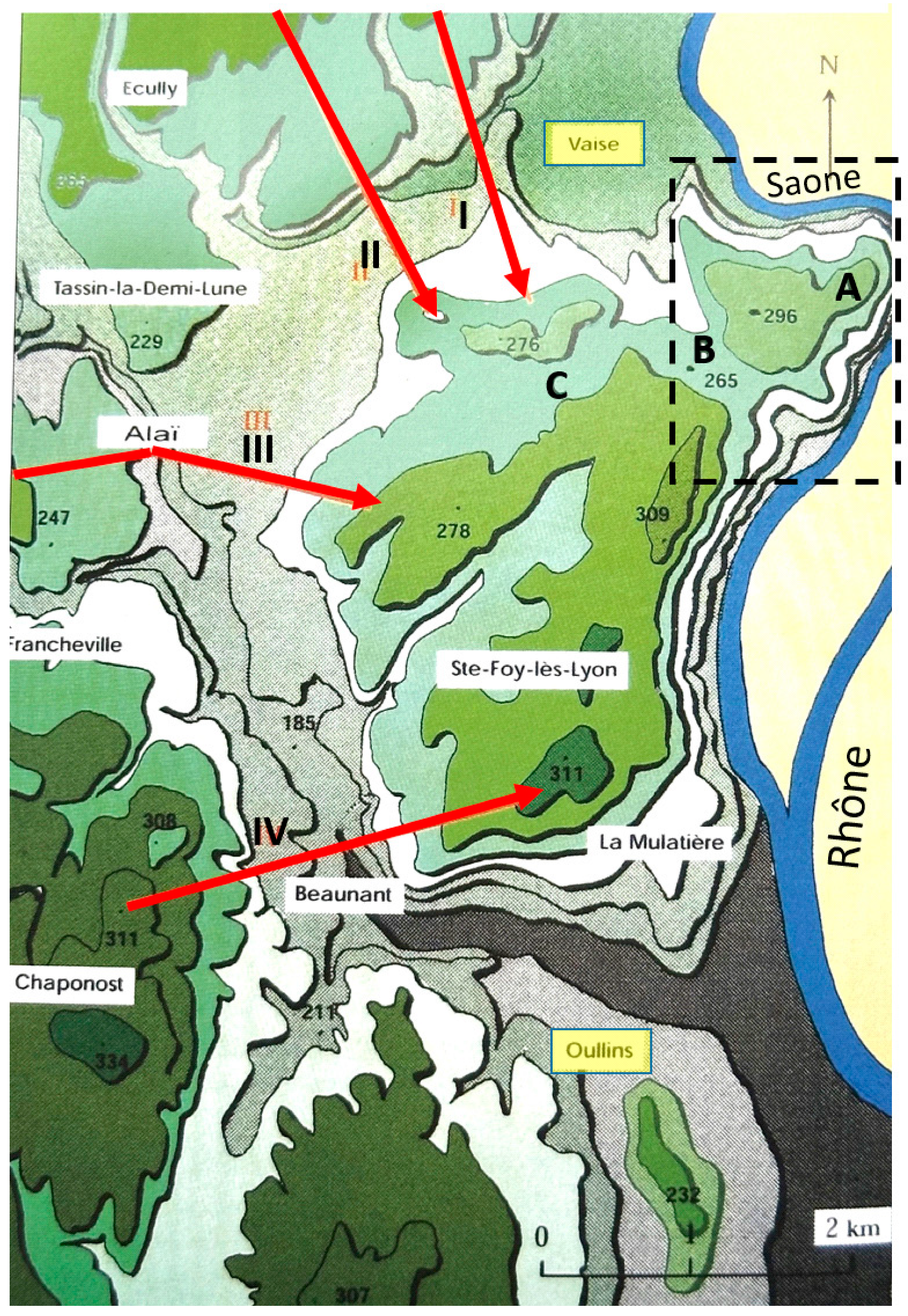







 highest areas, over 300 m. 1: uphill part of Yzeron siphon towards receiving tank; 2, 5, and 7: buried channel; 4: tunnel; 3, 6, and 8: bridge/channel on arches; 9: header tank of Trion siphon [9], p. 96, adapted.
 highest areas, over 300 m. 1: uphill part of Yzeron siphon towards receiving tank; 2, 5, and 7: buried channel; 4: tunnel; 3, 6, and 8: bridge/channel on arches; 9: header tank of Trion siphon [9], p. 96, adapted.