Article

Effect of Grain Size on the Uniaxial Compressive Strength of Ice Forming with Different Wind Speeds in a Cold Laboratory

by
Yujia Zhang
*,
Zuoqin Qian
,
Weilong Huang
,
Xiaodong Chen
,
Zhen Zhang
and
Jie Ren
School of Naval Architecture, Ocean and Energy Power Engineering, Wuhan University of Technology, Wuhan 430063, China
*
Author to whom correspondence should be addressed.
Water 2024, 16(14), 2049; https://doi.org/10.3390/w16142049
Submission received: 6 May 2024 / Revised: 1 July 2024 / Accepted: 18 July 2024 / Published: 19 July 2024
(This article belongs to the Special Issue Cold Region Hydrology and Hydraulics)

Abstract

:
This study investigated the uniaxial compressive strength of distilled water ice prepared in a low-temperature laboratory at −30 °C at varying wind speeds of 0 m/s, 1 m/s, 2 m/s, 4 m/s, 6 m/s, and 8 m/s. The crystal structure and grain size of the ice were measured. The results indicated that, during the ice forming period, the higher the wind speed, the lower the grain size. Uniaxial compression tests were conducted parallel to the ice crystal long axis direction within a strain rate range of 10−6 s−1 to 10−2 s−1. The experimental temperature was controlled at −10 °C. Stress–strain curves were generated, elucidating the mechanical properties and failure modes of the ice. The results suggest that the uniaxial compressive strength of ice is related to the strain rate by a power–law function and shows a linear correlation with −1/2 power of grain size. The results explain the physical fact that the strength of ice is higher when the ice is formed in low-temperature and high-wind-speed environments. Additionally, this highlights how wind speed influences ice strength by controlling grain size during ice forming.

1. Introduction

Ice is widely present in nature. Studies on shipping and energy exploration in cold regions often involve studying the mechanical properties of ice, as these industries are significantly influenced by local ice conditions [1,2]. The complex internal structure of ice results in its mechanical properties exhibiting diversity [3,4,5,6]. The interaction between ice and structures can lead to various modes of failure, such as compression, shear, and buckling, which are highly correlated with the compressive strength, bending strength, and shear strength of ice [7,8,9]. When subjected to continuous pressure, ice compression failure is the main mode of failure. In this case, the compressive strength of ice is the key to determining the process of sea ice failure and ice load [10,11,12].
The compressive strength of ice is influenced by various internal and external factors, with strain rate being one of the external factors. Previous studies have found that ice exhibits the coexistence of elasticity, plasticity, and viscoelasticity at different strain rates [13,14]. Bonath [15] conducted uniaxial compression tests on 410 one-year ice ridge specimens taken from the Barents Sea and Fram Strait at different strain rates, and found that, for mixed ice (a mixture of granular ice and columnar ice), the ductile compressive strength was higher than the brittle compressive strength. Moslet [16] also performed a series of uniaxial compression tests on sea ice in Svalbard, confirming the occurrence of both ductile and brittle behavior under different strain rates. Deng [17] found a transition in the failure mode of ice from ductile to brittle as the strain rate increased. Qi [18] studied the strain rate dependence of the uniaxial compressive strength of natural lake ice at moderate strain rates and found a positive correlation between compressive strength and strain rate within the selected strain rate range. Sain [19] conducted compression and tension tests at high strain rates, revealing a decrease in strength with increasing strain rates. Jones [20] studied the compressive strength of freshwater ice and sea ice at high strain rates and summarized the relationship between the stress and strain rate. Generally, the compressive strength of ice initially increases and then decreases with increasing strain rate, reaching its maximum value in the transition zone from ductile to brittle failure, known as the ductile-to-brittle transition regime [21,22,23]. Wang [24] conducted uniaxial compression tests in different loading directions within the strain rate range of 10−6 s−1 to 10−2 s−1. The ductile-to-brittle transition regime occurred between 10−4 s−1 and 10−3 s−1 for vertical loading and between 10−3 s−1 and 10−2 s−1 for horizontal loading. Han [25] investigated the compressive strength of Antarctic summer sea ice at different temperatures and found that the maximum compressive strength of sea ice was in the range of 10−3 s−1 to 10−1 s−1, and the strength gradually increased with the decrease in temperature.
The external environment will also affect the mechanical properties of ice, and temperature is one of the important factors. At present, most studies on the influence of temperature focused on the test temperature. Wu [26] investigated the dynamic behavior of polycrystalline ice under uniaxial compression within a temperature range of −15 °C to −173 °C. As the temperature decreased from −15 °C to −125 °C, the peak compressive strength increased from 32 MPa to 112 MPa. Barrette [27] studied the influences of temperature and pressure on the iceberg ice and laboratory-made ice under the condition of different confining pressures. Under the same confining pressure, the strength of the two kinds of ice increased with the decrease in temperature. A similar trend of strength variation with temperature was also found in atmospheric ice [28,29]. In our previous study, we maintained a constant test temperature and discussed the effect of growth temperature on ice strength. The results showed that the lower the growth temperature, the greater the maximum compressive strength of ice. The reason is that the growth temperature influences the growth process of ice, leading to the change in ice grain size and then affecting the strength [30].
Many research results also prove that ice crystal structure, grain size, and internal defects can directly affect the strength of ice [31,32,33]. Cole [34] conducted a uniaxial compression test on fresh water ice. When the strain rate increased to 10−5 s−1, the effect of grain size was more obvious, and the increase in grain size led to a decrease in peak stress of about 31%. Zhang [35] investigated the uniaxial compressive strength of reservoir ice and found that smaller grain sizes corresponded to higher strength. Jones [36] studied the effect of sample and grain sizes on the compressive strength of polycrystalline ice. It was found that sample sizes must be greater than 12 times the grain size for tests to produce compressive strength results independent of sample size. As for the influence of grain size, the results showed that the compressive strength had no significant dependence on the grain size in the range of 0.6–2.0 mm.
The formation and development of ice are affected by atmospheric conditions and ocean currents. In addition to temperature, wind speed is also a significant factor influencing the freezing process [37,38,39,40]. The purpose of this study was to investigate the effect of grain size on ice compressive strength under laboratory conditions, explain the physical mechanism of high ice strength at low temperatures and high wind speeds during ice formation, and supplement the study of the compressive strength of ice. Through a comprehensive analysis of the mechanical properties of ice, it provides a more comprehensive reference and guidance for ice-breaking strategies, navigation planning, and the design of structures in ice areas. In this study, the freezing of distilled water ice and the preparation of test samples were carried out in a low-temperature laboratory. The crystal structure and grain size of ice grown at different wind speeds were measured. Uniaxial compression tests were conducted at different strain rates, and the relationship between the compressive strength of ice grown under laboratory conditions and the strain rate and grain size was discussed. Section 2 introduces the methods of ice sample preparation, ice crystal structure measurement, and uniaxial compression test. Section 3 presents the measurement results of mechanical properties. Section 4 discusses and summarizes the results, and finally provides the conclusion.

2. Methods

2.1. Wind Tunnel

To ensure a stable wind speed during the process of freezing, it was necessary to control the wind speed using a wind tunnel in the laboratory. Considering manufacturing costs and spatial constraints, the wind tunnel was designed as an open-circuit low-speed wind tunnel, with its structure shown in Figure 1.
As for the wind tunnel in this study, the settling chamber and contraction section were processed as a whole, and the remaining sections were processed separately. For observation purposes, acrylic material was selected for the test section, and the remaining parts were made of stainless-steel plates. The contraction ratio was set to 7 and the maximum wind speed was 10 m/s. A wind tunnel device with a total length of 1425 mm was finally obtained. All sections were connected by flanges and nuts, as shown in Figure 2.

2.2. Preparation of Distilled Water Ice and Test Specimens

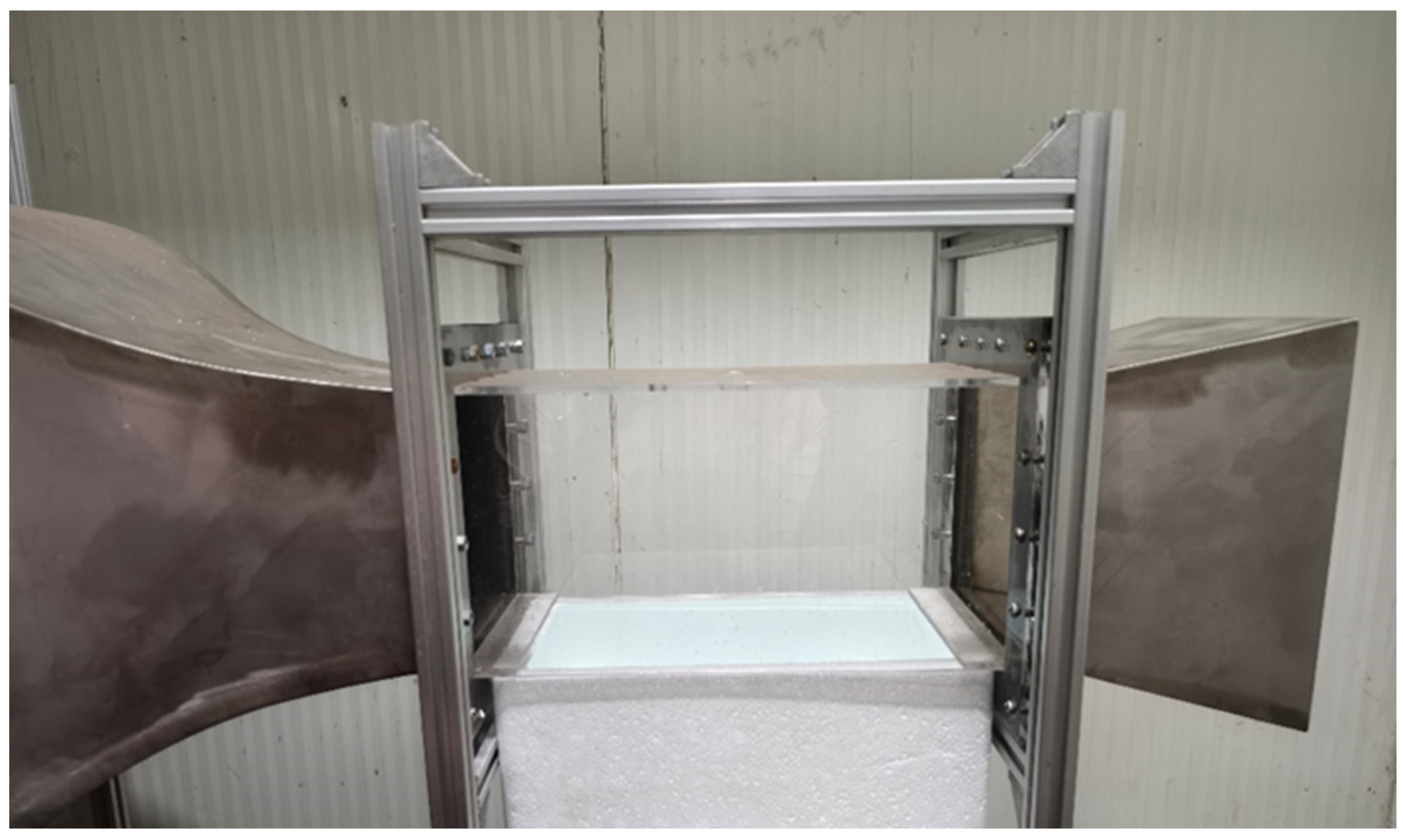
To mitigate the interference caused by salt and impurities within the ice, distilled water ice was chosen as the research subject. The foam box had the characteristics of low thermal conductivity, good thermal insulation, strong plasticity, and low cost, so it was used for condensation chambers. The combination of a condensation chamber and wind tunnel is shown in Figure 3. The ice formation process was conducted in a low-temperature laboratory where the temperature can be adjusted to as low as −40 °C, with a temperature control precision of 0.1 °C. To ignore the potential influence of growth temperature on ice strength, the freezing temperature was uniformly set to −30 °C, while the experimental temperature was uniformly set to −10 °C.
The wind speeds during the ice formation process were set at 0 m/s (no wind), 1 m/s, 2 m/s, 4 m/s, 6 m/s, and 8 m/s, respectively. Previous studies have indicated that the shape and dimensions of specimens can influence the strength of ice [41]. The International Association for Hydraulic Research (IAHR) has provided recommendations for uniaxial compression testing of ice specimens, suggesting that the cross-section of the test specimen should be square or circular, with a side length or diameter ranging from 7 to 10 cm. The length of the specimen should be 2.5 times its cross-sectional dimension [42]. Consequently, the specimens were machined into standard rectangular prisms measuring 7 cm × 7 cm × 17.5 cm.

2.3. Measurement Method for Ice Crystals

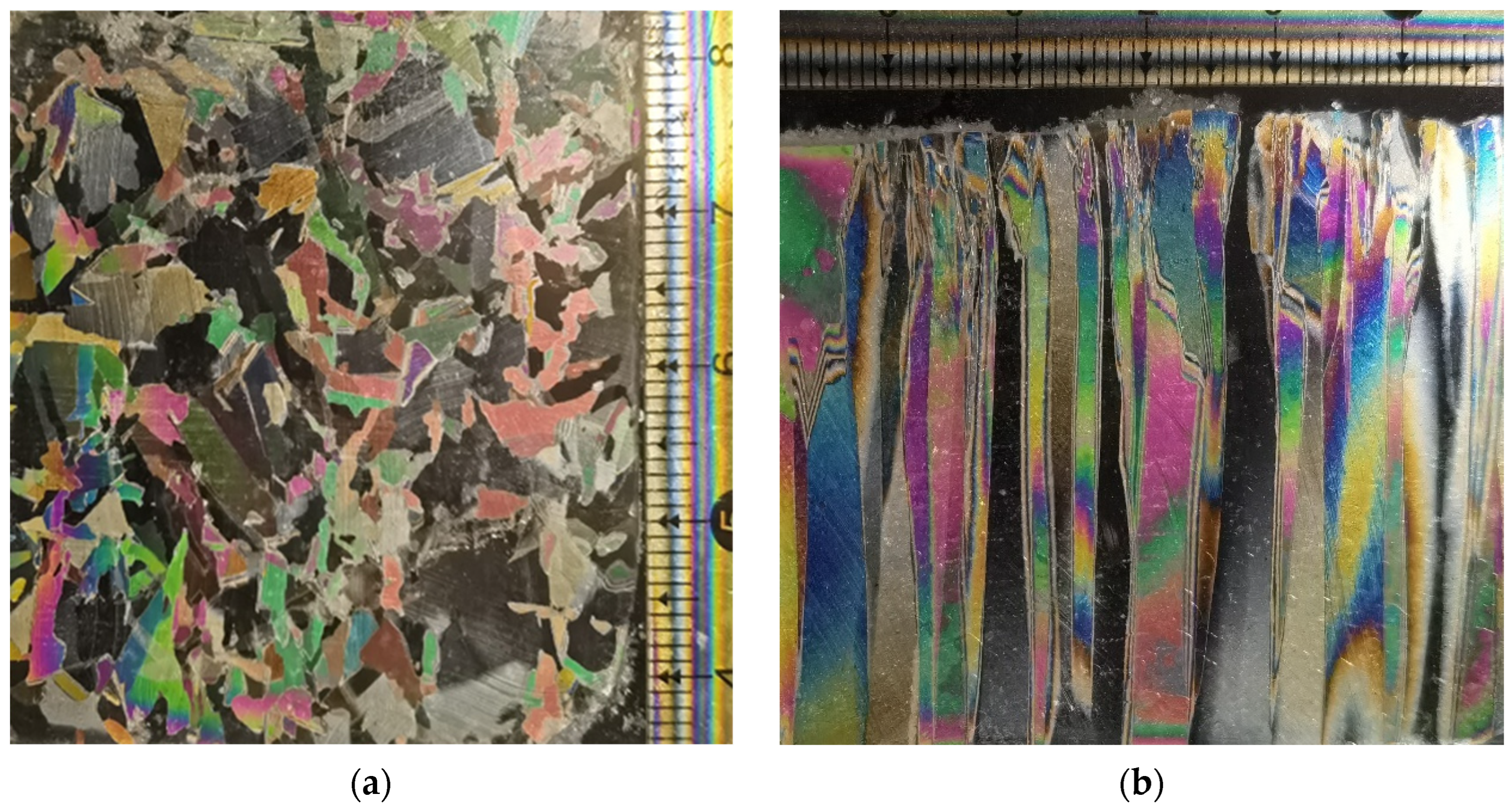
The ice crystal structure was observed through thin ice sheets attached to glass sheets. These sections were produced in the low-temperature laboratory. Ice samples were cut into sections with a side length of 5 cm and a thickness of 1 cm at different positions and divided into horizontal and vertical ice crystal measurements. The sections were attached to glass sheets slightly above 0 °C. After standing for 24 h in a low-temperature environment, the sections were thinned to less than 1 mm using a planer to facilitate clear observation of the ice crystal boundaries. The prepared sections were labeled with their information and stored in clean, sealed plastic bags. After the preparation of the slices, the ice crystal structure was observed under cross-polarized light using the device shown in Figure 4. The grain size is represented by the equivalent circular diameter of the average crystal area on the entire thin section [36]. The calculation formula is as follows [43]:
D g = 2 S n π
where D g is the average grain diameter (mm); S is the area of ice section (mm2); and n is the number of grains in the section.

2.4. Uniaxial Compression Test

2.4.1. Test Devices

The uniaxial compression test devices consisted of a universal testing machine and a low-temperature test chamber. The universal testing machine selected was the WDW-100 E model electronic universal testing machine produced by Jinan Chuance Test Equipment Co., Ltd., located in Jinan, Shandong, China. It has a maximum test force of 100 kN, test force measurement range of 0.4–100%FS (Full Scale), test force measurement accuracy better than ±0.5% of the indicated value, test force resolution of 1/500,000 of the full range, displacement measurement accuracy of ±0.5%, displacement resolution of 0.03 μm, displacement indication error of ±0.5%, deformation resolution of 0.001 mm, and beam speed adjustment range of 0.005–500 mm/min. Small springs are installed at the upper pressure plate to ensure tight contact between the pressure head and the specimen surface during testing. The low-temperature test chamber was used to provide the low-temperature test environment for preventing phase changes. It was located between the beam and the base of the testing machine. The DWC-40 low-temperature test chamber was selected, with an internal chamber size of 500 mm × 400 mm × 500 mm, temperature control range of −60 °C° to 0 °C, temperature control accuracy of 0.1 °C, and maximum cooling rate of 2 °C/min. The temperature sensor was located in the middle–left side of the low-temperature test chamber to monitor the temperature. The temperature inside the test chamber was verified by a mercury thermometer before the experiment, and the reading error between the two was ±0.1 °C. The temperature fluctuation range was ±0.5 °C. The test devices are shown in Figure 5.

2.4.2. Test Principle and Procedure

In engineering, the maximum compressive stress measured through experiments is commonly used to represent the uniaxial compressive strength of ice. The calculation method is as follows:
σ c = F m a x A
where F m a x is the maximum load on the load–time curve and A is the original cross-sectional area of the sample. The strain rate is controlled by adjusting the displacement rate X ˙ (mm/s) of the indenter, and the strain rate ε ˙ (s−1) during the test can be calculated by combining the original length L 0 (mm) of the sample as follows:
ε ˙ = X ˙ L 0
In this study, the strain rate range was from 10−6 s−1 to 10−2 s−1 and the loading direction was parallel to the ice crystal long axis. The test procedure is as follows: (1) Set the low-temperature test chamber to −10 °C and wait for it to reach thermal equilibrium. (2) Measure the length, width, and height of the ice specimen, seal it in a plastic bag, and then place it in the low-temperature test chamber for at least 24 h. (3) Position the specimen centrally beneath the lower plate. (4) Activate the testing machine control and data acquisition system. Adjust the position of the upper plate to make contact with the upper surface of the specimen and allow sufficient time for temperature stabilization to minimize temperature disturbances during specimen placement. (5) Configure the test parameters and start loading. (6) Cease loading immediately upon specimen failure. Capture photographs of the failed specimen. (7) Remove the failed specimen, clean any debris, and prepare for next test.

2.4.3. Test Errors

There were several potential sources of experimental error in the preparation and compression testing of samples. The first of which was the impact of temperature fluctuations. Although the test samples were stored in a low-temperature laboratory and the testing machine was equipped with a low-temperature chamber to provide the necessary environment during compression tests, the machine itself could not be placed in the low-temperature storage. This means that the samples inevitably passed through a room-temperature environment briefly when moving from the cold laboratory to the testing chamber. This brief exposure could cause temperature differences, leading to thermal stress. Thermal stress may induce pre-stress and pre-strain within the ice, potentially causing the measured compressive strength to be lower than the actual value. Secondly, wind speed variations can influence the results. In this study, the ice formation process of the samples was conducted at different wind speeds provided by a wind tunnel. Although a flow stabilizer was used to maintain a steady airflow within the tunnel, it was impossible to achieve a perfectly constant wind speed. Minor fluctuations in wind speed during the initial freezing stages could lead to variations in ice grain size, resulting in discrepancies between the measured strength and the true strength. Thirdly, measurement errors also contributed to potential inaccuracies. The stress for each sample was calculated based on the load and the cross-sectional area, which were measured manually. Manual measurements might not have perfectly reflected the actual dimensions, leading to stress values that were either overestimated or underestimated compared with theoretical values. Additionally, although the testing machine had high measurement precision, there were inherent measurement errors that could affect the results.

3. Results

3.1. Results of Ice Crystal Structure

The ice crystal structures of the thin sections cut horizontally and vertically in the laboratory were observed utilizing the method outlined in Section 2 and are shown in Figure 6. It can be seen that the ice sample used in the test was columnar ice, and the reasons for its formation could be explained as follows: the temperature in the low-temperature laboratory was almost constant throughout the freezing process, and the wind speed only caused certain disturbance to the water surface at the initial stage of freezing. When the surface was frozen, the air and water did not continue to be in direct contact, and the water body remained static, so the ice crystal had a stable growth environment and the crystal had enough time and space to grow stably. Each crystal could only grow downward because it was limited by other crystals around it, resulting in a columnar structure in the ice crystal.
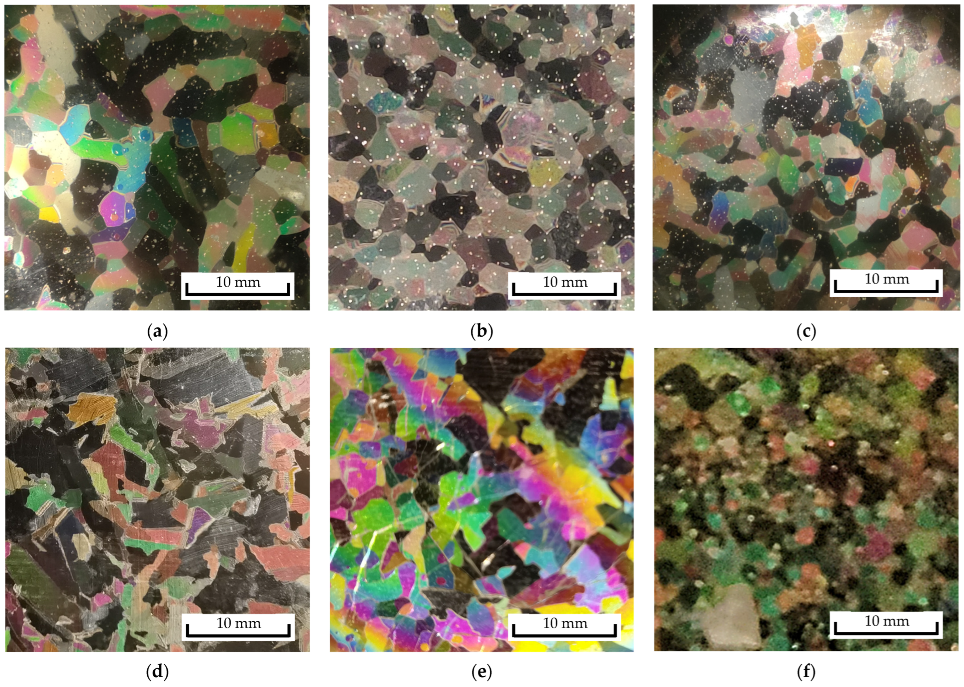
The ice crystal sizes at different depths under various wind speeds were measured and are summarized in Table 1. It is evident that, under the chosen wind speeds and temperature in this study, the ice crystal grain sizes ranged from 2 to 7 mm. The grain size tended to increase with depth, but decreased with increasing wind speed. This trend can be attributed to the slower crystallization rate resulting in larger grain sizes. An increase in wind speed increased the heat transfer coefficient at the water/ice interface, accelerating the freezing process and leading to smaller grain sizes. As the ice thickened during the freezing process, the thermal resistance between the unfrozen water and cold air increased, slowing down the freezing rate and resulting in larger grain sizes. Additionally, under low wind speeds, the increase in grain size was more significant compared with higher wind speeds. For instance, when the wind speed was 0 m/s, the grain size increased by 3.032 mm, whereas under an environment with a wind speed of 8 m/s, the grain size only increased by 0.98 mm. This phenomenon can also be explained by the influence of wind speed on the freezing rate. Under low wind speeds, the freezing process occurred more slowly, allowing the crystals more time to grow and increase in size. Ice crystal structures at 0 cm in the ice samples grown at different wind speeds are organized in Figure 7. The area of each section was 3 cm × 3 cm. It can be seen that, as the wind speed increased, the grain size became more uneven. The reason is that, during the freezing period, wind will cause disturbance to the water surface. The higher the wind speed, the more severe the disturbance, resulting in uneven surface crystal shapes.

3.2. Results of Uniaxial Compression Test

3.2.1. Failure Behavior of Ice

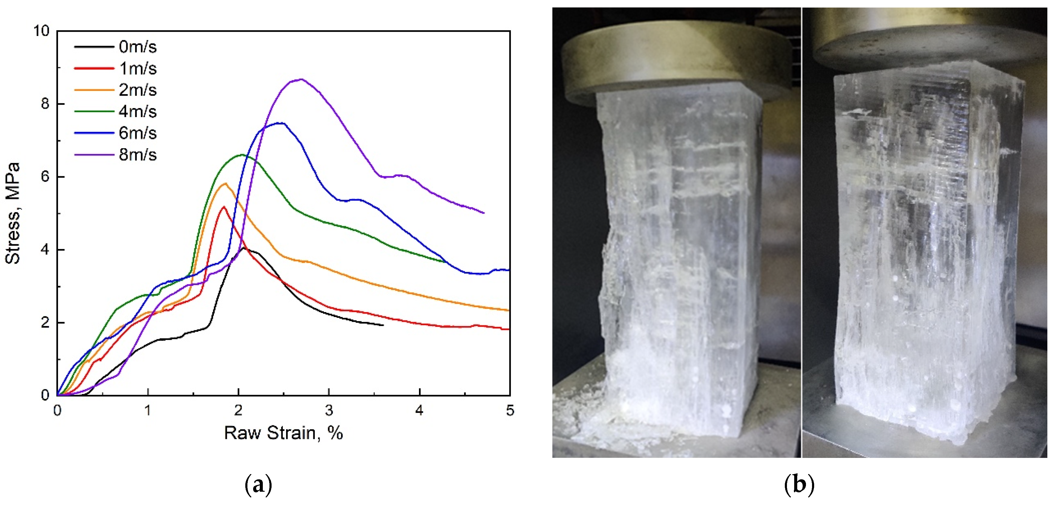
Ice undergoes ductile failure at low strain rates, and the stress–strain curve is shown in Figure 8. In the initial stage, the stress–strain curve often exhibited a nonlinear growth phase due to reasons such as uneven specimen cross-sections and incomplete contact between the indenter and the specimen. Before reaching the maximum stress value, there was a linear segment in the stress–strain curve, which reflected the linear deformation borne by the ice sample. Subsequently, the ice sample began to yield, and the stress gradually transitioned to its maximum value and began to decrease as deformation increased. In the ductile regime, slow loading induced noticeable deformation with minimal crack formation. As the loading rate increased, the number of cracks proliferated, resulting in longitudinal cleavage cracks that may penetrate through the specimen, causing it to expand. After losing strength, the ice sample remained structurally intact.
Ice exhibited brittleness only at high loading rates, and the typical stress–strain curve for brittle failure is depicted in Figure 9. As the testing indenter rapidly moved, the stress also increased swiftly. Upon reaching maximum stress, the ice sample suddenly fractured, shattering into multiple pieces, often containing large chunks. The overall structure was shattered, instantly losing its load-bearing capacity. During brittle fracture, once microcracks form within ice, they swiftly propagate into larger fissures, causing the ice sample to rapidly split into several parts. The fracture process was rapid, and the fractured pieces exhibited few internal cracks, often displaying flat, stepped, or fan-shaped fracture surfaces.
With the increase in strain rate, compressive strength underwent a process of an initial increase followed by a decrease. The peak limit stress of compressive strength occurred between the ductile and brittle regimes, termed the transition regime. In the transition regime, both ductile and brittle behaviors coexisted. However, from the stress–strain curve of the loading process, not only can we observe typical ductile and brittle process curves, as shown in Figure 8 and Figure 9, but it was even possible to simultaneously observe ductile and brittle characteristics within a single loading process (as shown in Figure 10).
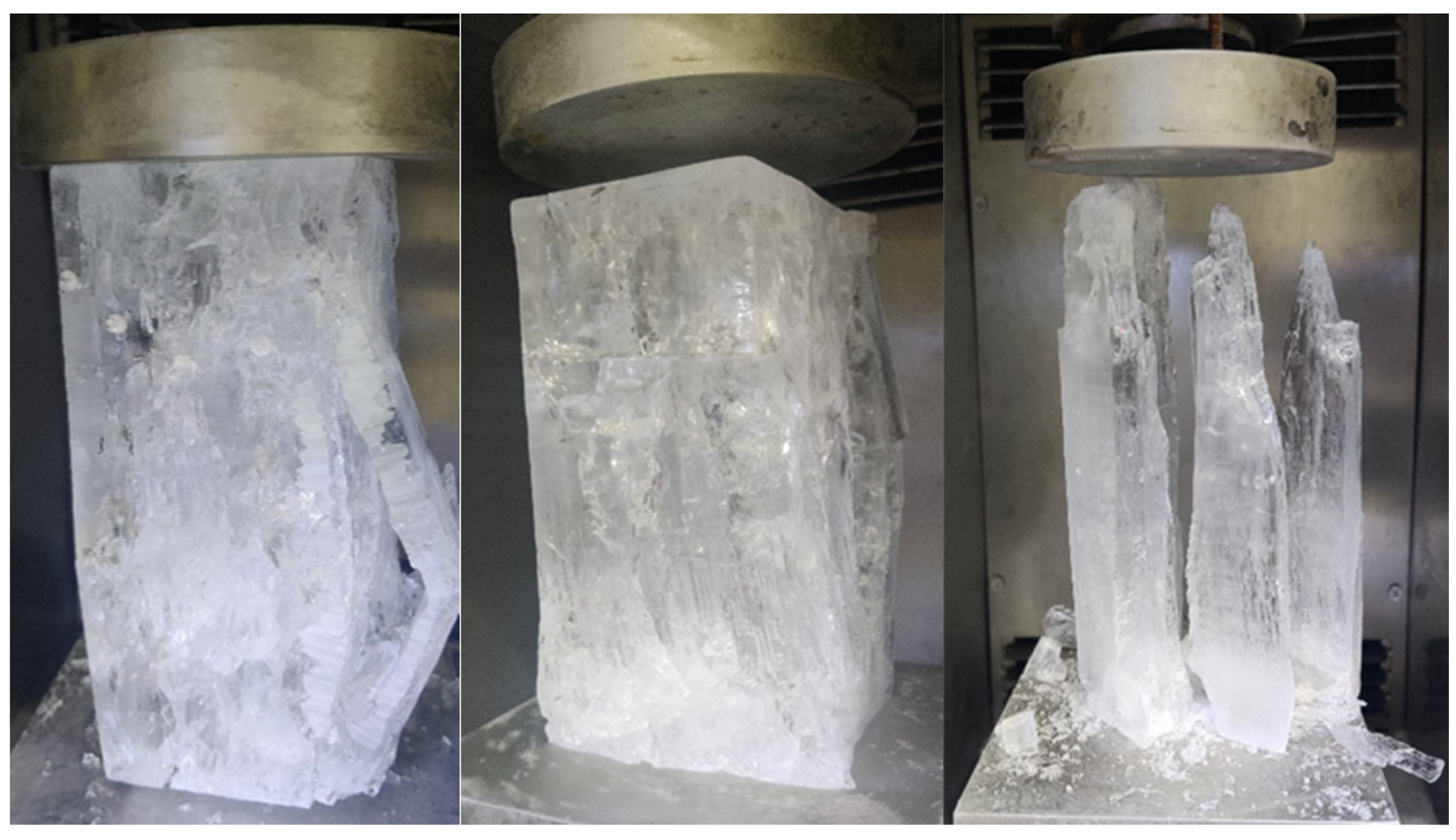
In addition to the large cracks that result in the fragmentation of samples during brittle failure, ice samples in the transition regime often exhibited numerous small cracks distributed evenly throughout various fragments, giving them a “whitish” appearance. Alternatively, during the moment of brittle failure, ice may collapse into numerous small pieces with a loud noise, displaying a pulverized failure mode. Different types of failure behavior of ice in the ductile–brittle transition regime is shown in Figure 11. In this study, the strain rate for the ductile–brittle transition of ice grown at different wind speeds during uniaxial compression was generally within the range of 1 × 10⁻⁴ s−1 to 5 × 10⁻⁴ s−1. Under no wind conditions (0 m/s), the coexistence of ductility and brittleness also occurred at a strain rate of 5 × 10⁻⁵ s−1. There was no clear pattern found in the current research regarding the transition regime. More experiments are needed to explore the actual range of the transition regime within the above strain rate range in order to determine its relationship with ice-forming wind speed or grain size. Therefore, understanding the mechanical behavior of ice requires conducting multiple experiments to identify general patterns.

3.2.2. Stress-Strain Curve Correction

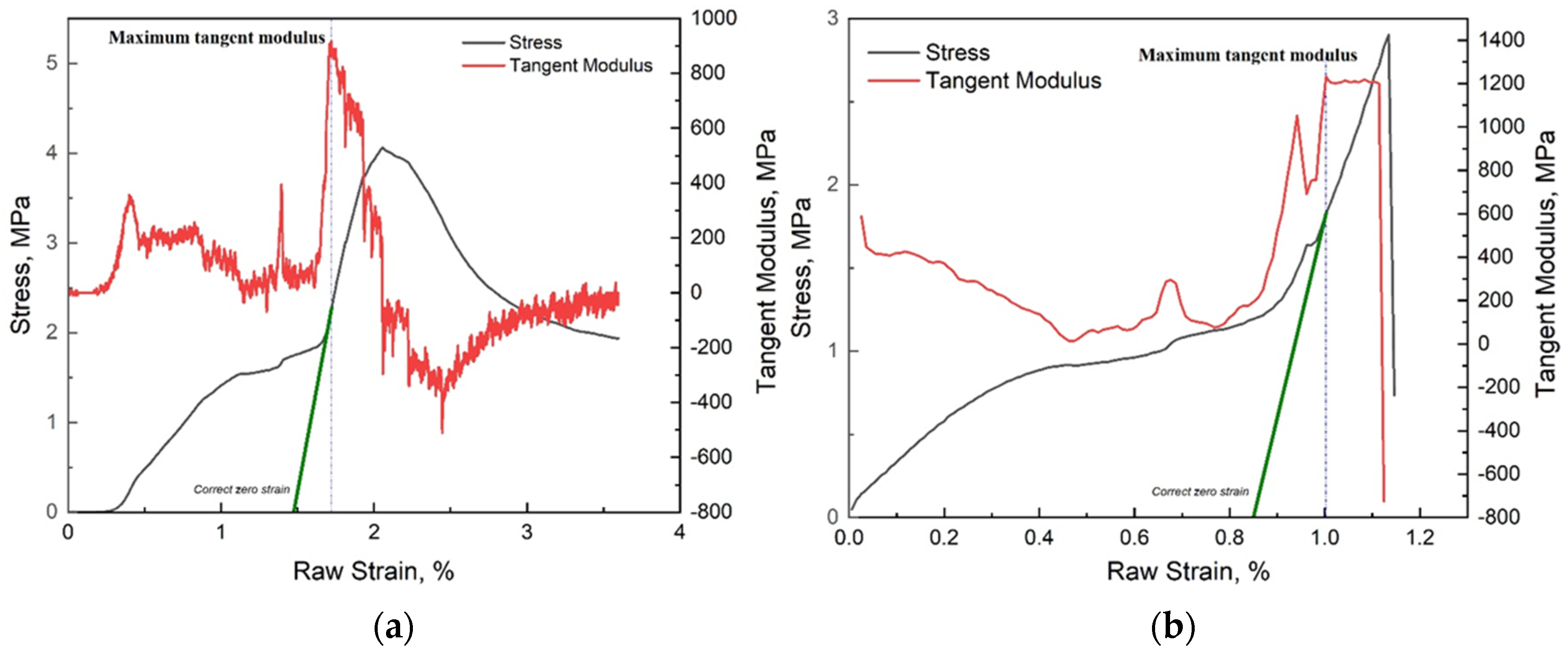
In the initial stage of compression testing, it was possible that the testing indenter did not fully conform to the surface of the sample. From the stress–strain curve, it can be observed that the curve initially rose rapidly after the start of the test, then flattened slightly, and subsequently increased linearly with a greater slope. Before the linear increase, the sample did not experience its true stress. Therefore, the correction of the stress–strain curve was necessary. Arakawa [44] proposed using the tangent modulus to estimate the true zero point of the stress–strain curve. The tangent modulus at a certain point on the curve was calculated by the ratio of the change in stress to the change in strain near that point. As shown in Figure 12a, the experimental results of a strain rate of 10−5 s−1 at a wind speed of 0 m/s demonstrated how the stress–strain curve was corrected when ice exhibited ductile behavior at low strain rates. When the raw strain reached 1.61%, the sample surface fully adhered to the pressure head, and the tangent modulus rose rapidly. It reached its maximum value of 917.44 MPa at a raw strain of 1.72%. By identifying the strain corresponding to the maximum tangent modulus, an auxiliary line (green line in Figure 12a) was drawn on the stress–strain curve with a slope equal to the maximum tangent modulus, intersecting the x-axis at the corrected zero point, which was 1.48% raw strain. After reaching its maximum value, the tangent modulus decreased rapidly with increasing strain. When the tangent modulus decreased to 0, the stress reached its maximum value of 4.06 MPa, defined as the maximum compressive strength under this condition, corresponding to a corrected strain of 0.58%. After reaching the peak, both the stress and tangent modulus decreased rapidly with increasing strain. The tangent modulus reached its minimum value at a corrected strain of 0.97%, and then gradually increased again, with the rate of decrease in stress also decreasing gradually until the stress eventually stabilized, and the tangent modulus approached 0. The method for correcting the stress–strain curve under brittle behavior at high strain rates was the same as for ductile behavior, as shown in Figure 12b.

4. Discussion

4.1. Stress Versus Strain Rate

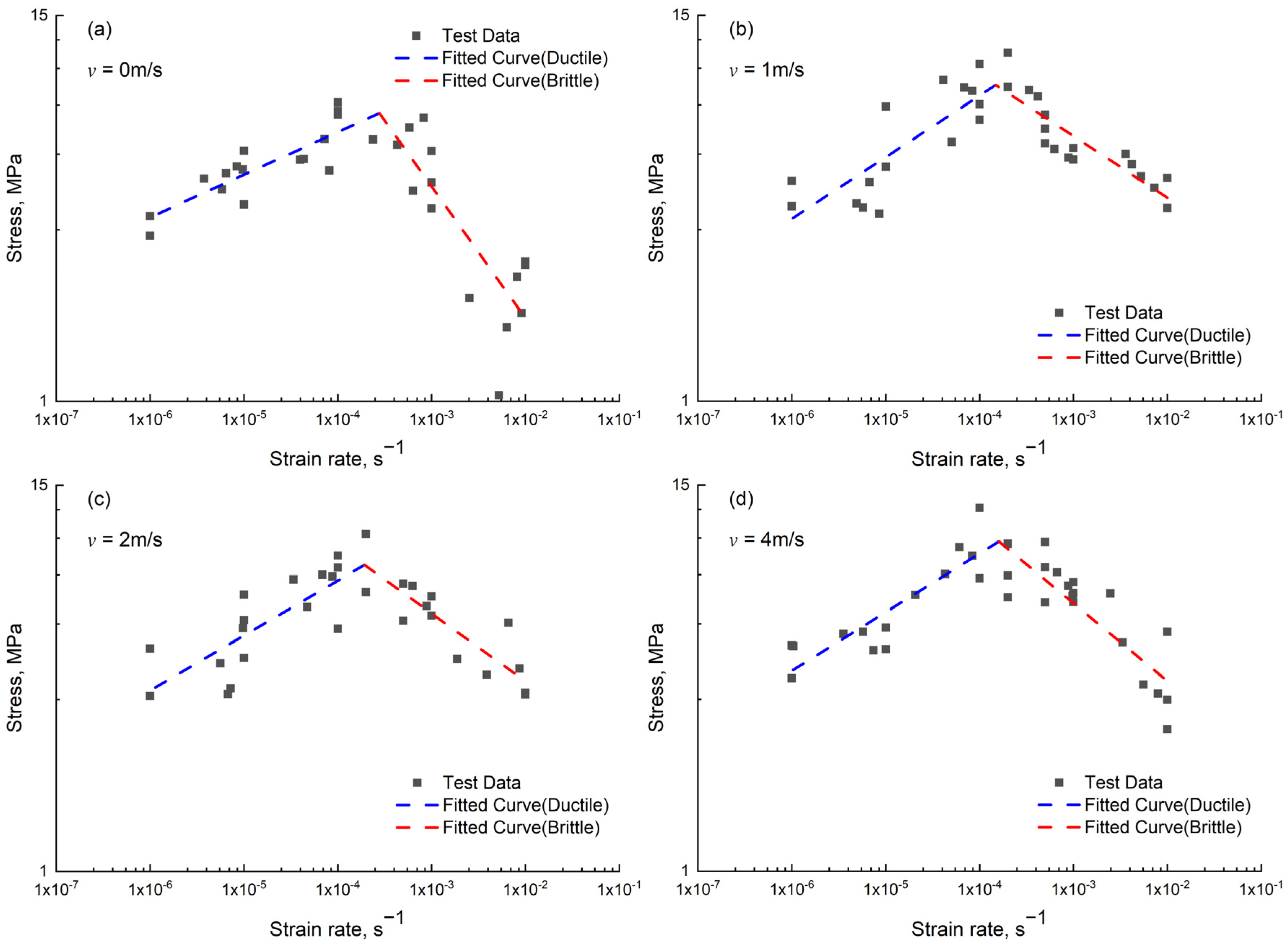
According to the results obtained from the uniaxial compression tests, it is evident that strain rate significantly influenced the compressive strength of ice. Within the selected range of strain rates (10−6 s−1 to 10−2 s−1), distinct mechanical characteristics were observed at different strain rates, indicating a notable sensitivity to strain rate variations. The results of uniaxial compression strength versus strain rate were plotted in the logarithmic coordinate system, with the maximum strength occurring in the ductile–brittle transition regime. Due to constraints imposed by the loading conditions of the testing apparatus in this study, the maximum loading rate was set at 10−2 s−1. Consequently, the variation in compressive strength at higher strain rates could not be investigated. Previous research suggests that ice strength tends to plateau beyond a certain strain rate threshold. Michel [45] suggested this threshold to be 10−2 s−1, while Wu [26] obtained similar results within the strain rate range of 80 s−1 to 600 s−1.
Observation of the scatter plot revealed that, within the ductile regime, the relationship between uniaxial compressive strength and strain rate followed a power–law function, consistent with the findings of Glen [46] in his study of ice creep characteristics. This relationship is expressed as:
ε ˙ = B σ c , v n
where B and n are empirical coefficients. To maintain dimensional consistency, Equation (4) is transformed into:
σ c , v σ 1 = B ε ˙ ε 1 ˙ n
Taking σ 1 = 1 MPa and ε 1 ˙ = 1 s−1 helps to standardize the expression. The relationship between uniaxial compressive strength and strain rate for the ductile regime of distilled water ice was fitted, and the fitted curve is depicted by the dashed line in Figure 13. The empirical coefficients and determination coefficients are provided in Table 2. As for the relationship between uniaxial compressive strength and strain rate in the brittle regime, there is currently no consensus. However, within the strain rate range of this study, the variation trend of uniaxial compressive strength with strain rate still approximated a power–law function. Therefore, fitting was conducted using Equation (5), and the fitted curve is shown by the dashed line in Figure 13, along with the corresponding empirical coefficients and determination coefficients provided in Table 2. It can be observed that the fitted curve aligned well with the experimental data. Previously, from the stress–strain curves, the ultimate failure stress of the ice, corresponding to the maximum compressive stress σ m a x , was determined. This compressive stress varied with different strain rates. By establishing the relationship between uniaxial compressive strength and strain rate, the peak uniaxial compressive strength σ c p was derived. Through the fitting function, the peak compressive strength σ c p of distilled water ice at different wind speeds could be calculated, and these values are also listed in Table 2.

4.2. Stress Versus Grain Size

In our preceding investigations, we extensively examined the relationship between growth temperature and the compressive strength of distilled water ice. Our findings demonstrated that growth temperature significantly influenced the strength of ice, achieved through the modulation of ice crystal grain size [30]. Both wind speed and air temperature are external environmental factors affecting the process of ice formation.
According the results shown in Section 3.1, the grain size of ice crystals varies with wind speed during ice formation. Grain size is one of the internal factors that affects the strength of ice. Generally, smaller grain sizes result in higher strength for a material. In the ductile regime, dislocations act as obstacles to the movement of crystals, making it more difficult for crystals to deform or fracture. When the grain size decreases to a certain extent, the density of dislocations between grains may increase. Dislocations are more likely to form and approach each other, but they are hindered by grain boundaries, limiting the movement of dislocations and thus increasing the strength. In the brittle regime, the mechanism of the effect of grain size on the strength is cleavage fracture theory. When the grain size decreases, the number of grain boundaries increases, and the propagation path of cleavage fracture is more hindered. In the case of large grains, cleavage cracks can easily propagate along the cleavage plane of the crystal. However, as the grain size decreases, cleavage cracks will encounter more grain boundaries during propagation, ultimately leading to an increase in strength. It was also found that the compressive stress was controlled by crack density in a microscopic extensile behavior study on brittle rocks [47]. There is currently no unified empirical formula to describe the relationship between ice strength and grain size. In the 1950s, Hall and Petch [48,49] summarized the relationship between the yield strength of polycrystalline materials and the reciprocal square root of grain size, known as the Hall–Petch relationship, as shown in Equation (6):
σ y = σ 0 + k c d 1 / 2
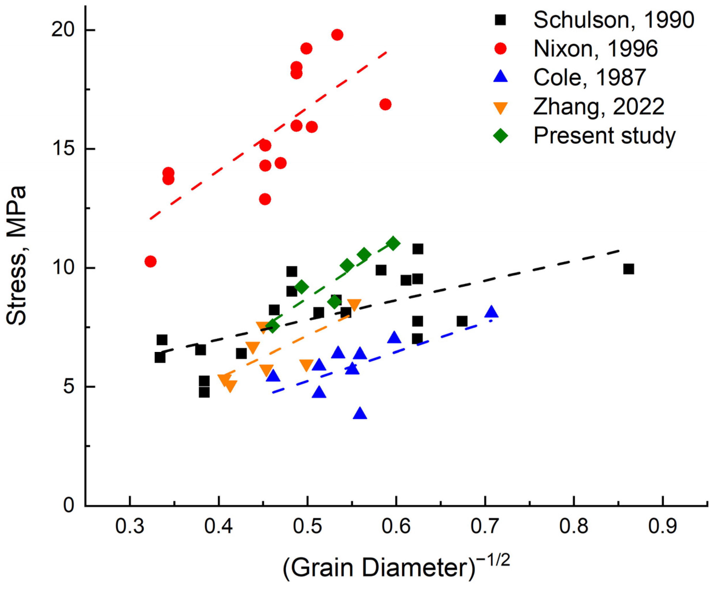
where σ y is yield strength, d is grain diameter, and σ 0 and k c are material constants. Schulson [50] used this as a reference and summarized the relationship between ice compressive strength and the equivalent diameter of grains in the brittle region. The yield strength in the original expression was replaced by compressive strength. Previous studies [50,51,52] have primarily focused on the impact of grain size on stress in the brittle region. In contrast, our research covers both the brittle and ductile regimes, allowing for a more comprehensive investigation into the relationship between the peak compressive strength of ice and grain size. Table 1 presents the average grain size of distilled water ice grown under different wind speeds. Combining this with the peak compressive strength σ c p calculated in Section 4.1 and fitted using Equation (6), we compare our research results with experimental and computational results from previous studies in Figure 14. Table 3 provides the empirical coefficients and determination coefficients for the stress–grain size relationships obtained in our study and other studies. From a numerical perspective, the maximum stress obtained in this study was roughly the same as the results of Schulson and Zhang, as the tests were all conducted at −10 °C. The stress obtained by Nixon was relatively high, while the results of Cole were relatively low, because the test temperatures were −50 °C and −5 °C, respectively. The lower the test temperature, the greater the compressive strength of the ice. It can be observed that stress is roughly linearly related to the −1/2 power of grain size, consistent with the notion that smaller grain sizes lead to higher strength. Figure 14 also includes the results of our previous study on compressive strength and growth temperature [30]. In this study, the growth temperature was maintained at −30 °C, and the compressive strength obtained after changing the wind speed was significantly higher than the results obtained under no-wind conditions in the previous study.
At present, there is little research on the impact of wind speed during the freezing period on ice strength. The peak compressive strength of ice under different wind speeds is given in Section 4.1. The results showed that the compressive strength was roughly positively correlated with the wind speed. When the wind speed reached 8 m/s, the uniaxial compressive strength reached the maximum value, and the peak compressive strength was 11.025 MPa, calculated by a fitting function. This is because the wind speed during icing affects the freezing process. The higher the wind speed, the greater the surface heat flux, and the faster the growth rate of ice crystals, the smaller the crystal particle size, ultimately leading to an increase in ice strength. The relationship between the grain size d and the peak compressive strength σ c p obtained in this study is as follows:
σ c p = 3.54 + 24.53 d 1 / 2
In the absence of other influencing factors, wind speed affects ice strength by controlling the grain size of ice crystals. This finding explains the physical fact that ice strength is higher when growing in extreme environments with low temperature and high wind speed in cold regions. It enriches the study of ice strength and helps in accurately assessing and evaluating the strength of ice bodies in engineering applications. It also provides theoretical support and technical assurance for selecting appropriate shipping routes and implementing suitable ice-breaking strategies to ensure safe navigation in cold water areas. Additionally, it offers an important reference for the design of structures on ice and risk mitigation measures. The results can help us to understand how ice strength varies with environmental conditions in natural settings. For instance, in polar regions, strong winds can lead to the formation of ice with smaller grains and thus higher strength, which affects ice stability and the formation of ice features, like ice ridges and leads.

5. Conclusions

This study utilized a self-designed small-scale low-speed open-circuit wind tunnel in a low-temperature laboratory to control icing wind speed and produce distilled water ice. The crystal structures of ice grown at different wind speeds were observed. Uniaxial compression tests were conducted on the distilled water ice samples grown at different wind speeds. The influences of strain rate and grain size on the uniaxial compressive strength of ice were analyzed. The following conclusions were drawn:
  • Wind speeds selected for ice freezing were 0 m/s, 1 m/s, 2 m/s, 4 m/s, 6 m/s, and 8 m/s. Columnar ice crystal structures were observed in this study, with grain sizes increasing with ice depth and ranging from 2–7 mm on average. Grain size tended to decrease with increasing wind speed.
  • Uniaxial compression tests were conducted on distilled water ice at strain rates ranging from 10−6 s−1 to 10−2 s−1. The results indicated that ice exhibited ductile behavior at low strain rates and brittle behavior at high strain rates. The uniaxial compressive strength of ice gradually increased with increasing strain rate, reaching a peak before decreasing with further increases in strain rate. A power function relationship between uniaxial compressive strength and strain rate was summarized through function fitting, and the peak compressive strength of ice was calculated.
  • The peak compressive strength of distilled water ice grown at different wind speeds was obtained, and the relationship between peak compressive strength and ice crystal grain size was discussed. The results showed that the peak compressive strength of ice gradually increased with the decrease in grain size, and the mathematical relationship between the two was obtained by fitting; that is, the peak compressive strength was linear with the −1/2 power of grain size. This also indicates that the wind speed during the icing process affected the ice compressive strength by controlling the grain size.

Author Contributions

Conceptualization, Y.Z. and Z.Q.; methodology, Y.Z.; software, J.R.; validation, Y.Z. and Z.Q.; formal analysis, Y.Z.; investigation, Z.Z.; resources, X.C.; data curation, Y.Z.; writing—original draft preparation, Y.Z.; writing—review and editing, Z.Q.; visualization, W.H.; supervision, Z.Q.; project administration, Z.Q. and Y.Z.; funding acquisition, Z.Q. All authors have read and agreed to the published version of the manuscript.

Funding

This research was funded by the National Natural Science Foundation of China, grant number 51676144.

Data Availability Statement

The original contributions presented in the study are included in the article, further inquiries can be directed to the corresponding author.

Acknowledgments

The authors would like to thank the Wuhan University of Technology (WUT).

Conflicts of Interest

The authors declare no conflicts of interest.

References

  1. Dempsey, J.P. Research trends in ice mechanics. Int. J. Solids Struct. 2000, 37, 131–153. [Google Scholar] [CrossRef]
  2. Beltaos, S.; Burrell, B.C. Hydrotechnical advances in Canadian river ice science and engineering during the past 35 years. Can. J. Civ. Eng. 2015, 42, 583–591. [Google Scholar] [CrossRef]
  3. Richter, M.J.A. US Research in ice mechanics: 1987–1990. Cold Reg. Sci. Technol. 1992, 20, 231–246. [Google Scholar] [CrossRef]
  4. Sinha, N.K.; Timco, G.W.; Frederking, R. Recent advances in ice mechanics in Canada. Appl. Mech. Rev. 1987, 40, 1214–1231. [Google Scholar] [CrossRef]
  5. Maattanen, M. Advance in ice mechanics in Finland. Appl. Mech. Rev. 1987, 40, 1120–1127. [Google Scholar] [CrossRef]
  6. Schwarz, J. Advances in ice mechanics in West Germany. Appl. Mech. Rev. 1987, 40, 1208–1213. [Google Scholar] [CrossRef]
  7. Petrovic, J.J. Review mechanical properties of ice and snow. J. Mater. Sci. 2003, 38, 1–6. [Google Scholar] [CrossRef]
  8. Taranukha, N.A.; Koshkin, S.V. Review and research of physical and mechanical properties for sea ice. In Proceedings of the Twenty-fourth International Ocean and Polar Engineering Conference, Busan, Republic of Korea, 15–20 June 2014. [Google Scholar]
  9. Cole, D.M.; Shapiro, L.H.; Weeks, W.F.; Byers, C.; Dempsey, J.P.; Adamson, R.M.; Petrenko, V.F.; Gluschenkov, O.V. Overview of recent program on mechanical properties of sea ice. J. Cold Reg. Eng. 1995, 9, 219–234. [Google Scholar] [CrossRef]
  10. Jones, S.J.; Gagnon, R.E.; Derradji, A.; Bugden, A. Compressive strength of iceberg ice. Can. J. Phys. 2003, 81, 191–200. [Google Scholar] [CrossRef]
  11. Lu, W.; Lubbad, R.; Løset, S.; Kashafutdinov, M. Fracture of an ice floe: Local out-of-plane flexural failures versus global in-plane splitting failure. Cold Reg. Sci. Technol. 2016, 123, 1–13. [Google Scholar] [CrossRef]
  12. Paquette, E.; Brown, T.G. Ice crushing forces on offshore structures: Global effective pressures and the ISO 19906 design equation. Cold Reg. Sci. Technol. 2017, 142, 55–68. [Google Scholar] [CrossRef]
  13. Sinha, N.K. Uniaxial compressive strength of first-year and multi-year sea ice. Can. J. Civ. Eng. 1984, 11, 82–91. [Google Scholar] [CrossRef]
  14. Sinha, N.K. Rheology of columnar-grained ice. Exp. Mech. 1978, 18, 464–470. [Google Scholar] [CrossRef]
  15. Bonath, V.; Edeskär, T.; Lintzén, N.; Fransson, L.; Cwirzen, A. Properties of ice from first-year ridges in the Barents Sea and Fram Strait. Cold Reg. Sci. Technol. 2019, 168, 102890. [Google Scholar] [CrossRef]
  16. Moslet, P.O. Field testing of uniaxial compression strength of columnar sea ice. Cold Reg. Sci. Technol. 2007, 48, 1–14. [Google Scholar] [CrossRef]
  17. Deng, K.; Feng, X.; Tian, X.; Hu, Y. Experimental research on compressive mechanical properties of ice under low strain rates. Mater. Today Commun. 2020, 24, 101029. [Google Scholar] [CrossRef]
  18. Qi, C.; Lian, J.; Ouyang, Q.; Zhao, X. Dynamic compressive strength and failure of natural lake ice under moderate strain rates at near melting point temperature. Lat. Am. J. Solids struct. 2017, 14, 1669–1694. [Google Scholar] [CrossRef]
  19. Sain, T.; Narasimhan, R. Constitutive modeling of ice in the high strain rate regime. Int. J. Solids. Struct. 2011, 48, 817–827. [Google Scholar] [CrossRef]
  20. Jones, S.J. High strain-rate compression tests on ice. J. Phys. Chem. B 1997, 101, 6099–6101. [Google Scholar] [CrossRef]
  21. Batto, R.A.; Schulson, E.M. On the ductile-to-brittle transition in ice under compression. Acta Metall. Mater. 1993, 41, 2219–2225. [Google Scholar] [CrossRef]
  22. Snyder, S.A.; Schulson, E.M.; Renshaw, C.E. Effects of prestrain on the ductile-to-brittle transition of ice. Acta Mater. 2016, 108, 110–127. [Google Scholar] [CrossRef]
  23. Wu, Y.; Lou, X.; Liu, X.; Pronk, A. The property of fiber reinforced ice under uniaxial compression. Mater. Struct. 2020, 53, 29. [Google Scholar] [CrossRef]
  24. Wang, Q.; Li, Z.; Lu, P.; Xu, Y.; Li, Z. Flexural and compressive strength of the landfast sea ice in the Prydz Bay, East Antarctic. Cryosphere 2022, 16, 1941–1961. [Google Scholar] [CrossRef]
  25. Han, H.; Li, Z.; Huang, W.; Lu, P.; Lei, R. The uniaxial compressive strength of the Arctic summer sea ice. Acta. Oceanol. Sin. 2015, 34, 129–136. [Google Scholar] [CrossRef]
  26. Wu, X.; Prakash, V. Dynamic compressive behavior of ice at cryogenic temperatures. Cold Reg. Sci. Technol. 2015, 118, 1–13. [Google Scholar] [CrossRef]
  27. Barrette, P.D.; Jordaan, I.J. Pressure–temperature effects on the compressive behavior of laboratory-grown and iceberg ice. Cold Reg. Sci. Technol. 2003, 36, 25–36. [Google Scholar] [CrossRef]
  28. Kermani, M.; Farzaneh, M.; Gagnon, R. Compressive strength of atmospheric ice. Cold Reg. Sci. Technol. 2007, 49, 195–205. [Google Scholar] [CrossRef]
  29. Farid, H.; Saeidi, A.; Farzaneh, M. Prediction of failure in atmospheric ice under triaxial compressive stress. Cold Reg. Sci. Technol. 2017, 138, 46–56. [Google Scholar] [CrossRef]
  30. Zhang, Y.; Qian, Z.; Lv, S.; Huang, W.; Ren, J.; Fang, Z.; Chen, X. Experimental investigation of uniaxial compressive strength of distilled water ice at different growth temperatures. Water 2022, 14, 4079. [Google Scholar] [CrossRef]
  31. Kuehn, G.A.; Schulson, E.M.; Jones, D.E.; Zhang, J. The compressive strength of ice cubes of different sizes. J. Offshore Mech. Arct. Eng. 1993, 115, 142–148. [Google Scholar] [CrossRef]
  32. Litwin, K.L.; Zygielbaum, B.R.; Polito, P.J.; Sklar, L.S.; Collins, G.C. Influence of temperature, composition, and grain size on the tensile failure of water ice: Implications for erosion on Titan. J. Geophys. Res. 2012, 117, E08013. [Google Scholar] [CrossRef]
  33. Georges, D.; Saletti, D.; Montagnat, M.; Forquin, P.; Hagenmuller, P. Influence of porosity on ice dynamic tensile behavior as assessed by spalling tests. J. Dyn. Behav. Mater. 2021, 7, 575–590. [Google Scholar] [CrossRef]
  34. Cole, D.M. Grain size and the compressive strength of ice. J. Energy Resour. Technol. 1985, 107, 369–374. [Google Scholar] [CrossRef]
  35. Zhang, L.; Li, Z.; Jia, Q.; Huang, W. Experimental study on uniaxial compressive strength of reservoir ice. Trans. Tianjin Univ. 2012, 18, 112–116. [Google Scholar] [CrossRef]
  36. Jones, S.J.; Chew, H.A.M. Effect of sample and grain size on the compressive strength of ice. Ann. Glaciol. 1983, 4, 129–132. [Google Scholar] [CrossRef]
  37. Fujisaki, A.; Oey, L. Formation of ice bands by winds. J. Geophys. Res. 2011, 116, C10015. [Google Scholar] [CrossRef]
  38. Rallabandi, B.; Zheng, Z.; Winton, M.; Stone, H.A. Formation of sea ice bridges in narrow straits in response to wind and water stresses. J. Geophys. Res. Ocean. 2017, 122, 5588–5610. [Google Scholar] [CrossRef]
  39. Ashton, G.D. River and lake ice thickening, thinning, and snow ice formation. Cold Reg. Sci. Technol. 2011, 68, 3–19. [Google Scholar] [CrossRef]
  40. Liu, R.; Liu, Y.; Wang, Q.; Yi, X. Investigation of microstructure and density of atmospheric ice formed by high-wind-speed in-cloud icing. Crystals 2023, 13, 1015. [Google Scholar] [CrossRef]
  41. Timco, G.W.; Frederking, R.M.W. Comparative strengths of fresh water ice. Cold Reg. Sci. Technol. 1982, 6, 21–27. [Google Scholar] [CrossRef]
  42. Schwarz, J.; Frederking, R.; Gavrillo, V.; Petrov, I.G.; Hirayama, K.I.; Mellor, M.; Tryde, P.; Vaudrey, K.D. Standardized testing methods for measuring mechanical properties of ice. Cold Reg. Sci. Technol. 1981, 4, 245–253. [Google Scholar] [CrossRef]
  43. Jacka, T.H. Laboratory studies on relationships between ice crystal size and flow rate. Cold Reg. Sci. Technol. 1984, 10, 31–42. [Google Scholar] [CrossRef]
  44. Arakawa, M.; Maeno, N. Mechanical strength of polycrystalline ice under uniaxial compression. Cold Reg. Sci. Technol. 1997, 26, 215–229. [Google Scholar] [CrossRef]
  45. Michel, B.; Toussaint, N. Mechanisms and theory of indentation of ice plates. J. Glaciol. 1977, 19, 285–300. [Google Scholar] [CrossRef]
  46. Glen, J.W. The creep of polycrystalline ice. Proc. R. Soc. A-Math. Phy. 1955, 228, 519–538. [Google Scholar] [CrossRef]
  47. Lan, H.; Martin, C.D.; Hu, B. Effect of heterogeneity of brittle rock on micromechanical extensile behavior during compression loading. J. Geophys. Res. 2010, 115, B01202. [Google Scholar] [CrossRef]
  48. Hall, E.O. The deformation and ageing of mild steel: III discussion of results. Proc. Phys. Soc. Lond. B 1951, 64, 747–753. [Google Scholar] [CrossRef]
  49. Petch, N.J. The Cleavage Strength of Polycrystals. J. Iron Steel Inst. 1953, 174, 25–28. [Google Scholar]
  50. Schulson, E.M. The brittle compressive fracture of ice. Acta Metall. Mater. 1990, 38, 1963–1976. [Google Scholar] [CrossRef]
  51. Cole, D.M. Strain-rate and grain-size effects in ice. J. Glaciol. 1987, 33, 274–280. [Google Scholar] [CrossRef]
  52. Nixon, W.A. Wing crack models of the brittle compressive failure of ice. Cold Reg. Sci. Technol. 1996, 24, 41–55. [Google Scholar] [CrossRef]
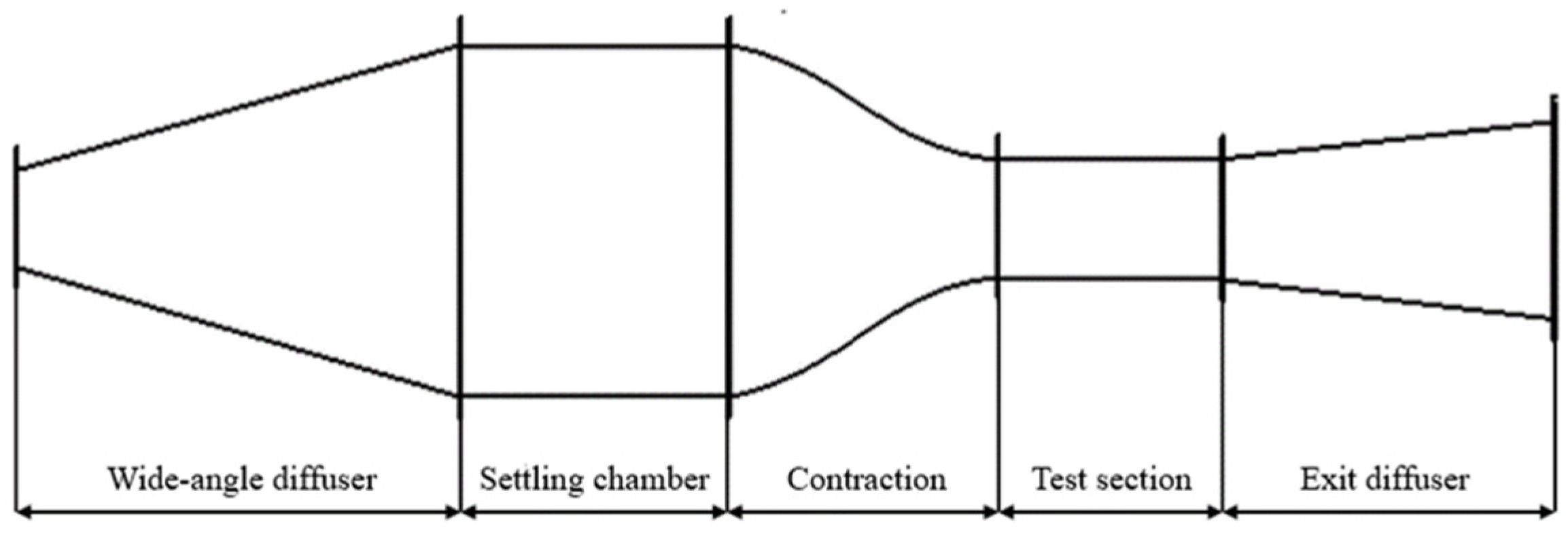
Figure 1. Structure of a typical open-circuit low-speed wind tunnel.
Water 16 02049 g001
Figure 2. Open-circuit low-speed wind tunnel in laboratory.
Water 16 02049 g002
Figure 3. Ice condensation chamber and test section.
Water 16 02049 g003
Figure 4. Ice crystal observation equipment.
Water 16 02049 g004
Figure 5. Test devices in this study. (a) WDW-100E electronic universal testing machine, (b) testing zone, (c) low-temperature test chamber.
Water 16 02049 g005
Figure 6. Thin sections of distilled water ice grown under 4 m/s photographed in polarized light. (a) Horizontal section at the thickness of 0 cm (top) and (b) vertical section of 0–5 cm.
Water 16 02049 g006
Figure 7. Ice crystal structure at 0 cm in ice samples grown at different wind speeds. (af) Samples grown at 0 m/s, 1 m/s, 2 m/s, 4 m/s, 6 m/s, and 8 m/s respectively.
Water 16 02049 g007
Figure 8. Stress–strain curve (a) and failure behavior (b) in ductile regime. The loading strain rate of (a) is 1 × 10⁻⁵ s−1.
Water 16 02049 g008
Figure 9. Stress–strain curve (a) and different performances of failure behavior (b) under brittle regime. The loading strain rate of (a) was 1 × 10⁻³ s−1.
Water 16 02049 g009
Figure 10. Stress–strain curve with both ductile and brittle characteristics. The sample was from ice grown at a wind speed of 0 m/s and the loading strain rate was 1 × 10⁻⁴ s−1.
Water 16 02049 g010
Figure 11. Different types of failure behavior of ice in ductile–brittle transition regime.
Water 16 02049 g011
Figure 12. Correction of stress–strain curve. (a) Result of the sample grown at a wind speed of 0 m/s, and the loading strain rate was 1 × 10⁻⁵ s−1 for ductile regime explanation. (b) Result of the sample grown at a wind speed of 0 m/s, and the loading strain rate was 1 × 10⁻³ s−1 for brittle regime explanation.
Water 16 02049 g012
Figure 13. Test data of uniaxial compressive strength versus strain rate and fitted curves for distilled water ice samples grown at different wind speeds. (af) Results of samples grown at 0 m/s, 1 m/s, 2 m/s, 4 m/s, 6 m/s, and 8 m/s respectively.
Water 16 02049 g013aWater 16 02049 g013b
Figure 14. Stress versus grain size (Data from Schulson (1990) [50], Nixon (1996) [52], Cole (1987) [51], Zhang (2022) [30], and present study) and fitted curves.
Water 16 02049 g014
Table 1. Grain size measurement results of different wind speeds and depths (Unit: mm).
Wind Speed/Depth0 cm5 cm10 cm15 cmAverage
0 m/s3.1204.2035.3686.1524.711
1 m/s3.1373.6644.5475.0894.110
2 m/s2.9263.5513.8433.9033.556
4 m/s2.6043.5273.6493.7103.373
6 m/s2.6713.0013.2573.6593.147
8 m/s2.1232.9393.0813.1032.812
Table 2. Fitting coefficients and coefficients of determination R 2 of uniaxial compressive strength tests on distilled water ice.
. v
(m/s)
Ductile RegimeBrittle Regime σ c p
(MPa)
BnR2BnR2
021.8220.1300.670.283−0.4010.737.552
147.9500.1870.661.754−0.1880.769.193
235.2780.1670.641.461−0.2070.748.574
448.0580.1770.761.274−0.2370.6710.096
640.8110.1700.750.765−0.330.7210.560
842.1340.1560.741.237−0.2550.6711.025
Table 3. Regression and correlation coefficients for stress vs. grain size fitting function.
Schulson, 1990 [50]Nixon, 1996 [52]Cole, 1987 [51]Zhang, 2022 [30]Present Study
σ 0 3.673.52−0.89−1.81−3.54
k c 8.2726.412.2517.9124.53
R20.440.560.450.540.84
Disclaimer/Publisher’s Note: The statements, opinions and data contained in all publications are solely those of the individual author(s) and contributor(s) and not of MDPI and/or the editor(s). MDPI and/or the editor(s) disclaim responsibility for any injury to people or property resulting from any ideas, methods, instructions or products referred to in the content.